EP1544878B1 - Verriegelbare Befestigung für Schutzschalter - Google Patents
Verriegelbare Befestigung für Schutzschalter Download PDFInfo
- Publication number
- EP1544878B1 EP1544878B1 EP04030031A EP04030031A EP1544878B1 EP 1544878 B1 EP1544878 B1 EP 1544878B1 EP 04030031 A EP04030031 A EP 04030031A EP 04030031 A EP04030031 A EP 04030031A EP 1544878 B1 EP1544878 B1 EP 1544878B1
- Authority
- EP
- European Patent Office
- Prior art keywords
- fastener
- threaded
- circuit breaker
- set forth
- locking member
- Prior art date
- Legal status (The legal status is an assumption and is not a legal conclusion. Google has not performed a legal analysis and makes no representation as to the accuracy of the status listed.)
- Expired - Fee Related
Links
- 239000004020 conductor Substances 0.000 claims description 27
- 230000015572 biosynthetic process Effects 0.000 description 1
- 230000001419 dependent effect Effects 0.000 description 1
- 238000010438 heat treatment Methods 0.000 description 1
- 230000001771 impaired effect Effects 0.000 description 1
- 230000002452 interceptive effect Effects 0.000 description 1
- 230000004048 modification Effects 0.000 description 1
- 238000012986 modification Methods 0.000 description 1
- 230000005405 multipole Effects 0.000 description 1
Images


Classifications
-
- F—MECHANICAL ENGINEERING; LIGHTING; HEATING; WEAPONS; BLASTING
- F16—ENGINEERING ELEMENTS AND UNITS; GENERAL MEASURES FOR PRODUCING AND MAINTAINING EFFECTIVE FUNCTIONING OF MACHINES OR INSTALLATIONS; THERMAL INSULATION IN GENERAL
- F16B—DEVICES FOR FASTENING OR SECURING CONSTRUCTIONAL ELEMENTS OR MACHINE PARTS TOGETHER, e.g. NAILS, BOLTS, CIRCLIPS, CLAMPS, CLIPS OR WEDGES; JOINTS OR JOINTING
- F16B39/00—Locking of screws, bolts or nuts
- F16B39/02—Locking of screws, bolts or nuts in which the locking takes place after screwing down
- F16B39/028—Locking of screws, bolts or nuts in which the locking takes place after screwing down by means of an auxiliary bolt or threaded element whose action provokes the deformation of the main bolt or nut and thereby its blocking
-
- H—ELECTRICITY
- H01—ELECTRIC ELEMENTS
- H01H—ELECTRIC SWITCHES; RELAYS; SELECTORS; EMERGENCY PROTECTIVE DEVICES
- H01H1/00—Contacts
- H01H1/58—Electric connections to or between contacts; Terminals
- H01H1/5833—Electric connections to or between contacts; Terminals comprising an articulating, sliding or rolling contact between movable contact and terminal
-
- F—MECHANICAL ENGINEERING; LIGHTING; HEATING; WEAPONS; BLASTING
- F16—ENGINEERING ELEMENTS AND UNITS; GENERAL MEASURES FOR PRODUCING AND MAINTAINING EFFECTIVE FUNCTIONING OF MACHINES OR INSTALLATIONS; THERMAL INSULATION IN GENERAL
- F16B—DEVICES FOR FASTENING OR SECURING CONSTRUCTIONAL ELEMENTS OR MACHINE PARTS TOGETHER, e.g. NAILS, BOLTS, CIRCLIPS, CLAMPS, CLIPS OR WEDGES; JOINTS OR JOINTING
- F16B5/00—Joining sheets or plates, e.g. panels, to one another or to strips or bars parallel to them
- F16B5/02—Joining sheets or plates, e.g. panels, to one another or to strips or bars parallel to them by means of fastening members using screw-thread
- F16B5/0275—Joining sheets or plates, e.g. panels, to one another or to strips or bars parallel to them by means of fastening members using screw-thread the screw-threaded element having at least two axially separated threaded portions
Definitions
- the present invention relates generally to circuit breakers and, more particularly, to a fastener that can be employed in a circuit breaker application, the fastener being lockable to resist release of the fastener.
- Circuit breakers are employed in diverse capacities in power distribution systems.
- An exemplary configuration of a circuit breaker would include a line conductor, a load conductor, a fixed contact, and a movable contact, with the movable contact being movable into and out of electrically conductive engagement with the fixed contact to switch the circuit breaker between the ON position and the OFF or TRIPPED positions.
- the fixed contact is electrically conductively engaged with one of the line and load conductors
- the movable contact is electrically conductively engaged with the other of the line and load conductors.
- the movable contact is typically disposed on a movable contact arm.
- the movable arm may be disposed upon a structure within the interior of the circuit breaker and a flexible shunt employed to electrically conductively connect the movable arm with its associated conductor.
- a fastener may be employed in making the pivotable connection between the movable arm and the conductor. The fastener must provide sufficient contact forces between the conductor and the movable arm to provide electrically conductive engagement therebetween, however the contact forces cannot be so great as to cause so much friction between the movable arm and the conductor that the pivoting action of the arm is impaired.
- Document US 2002/127082 discloses a fastener having male and female sections, each section having an elongate portion and a head with an outer diameter larger than that of the elongate portion.
- the elongate portion of the male section has external threads
- the elongate portion of the female section has internal threads for engaging the threads of the male section.
- the outer end of the male section is castellated and has a threaded cavity.
- the head of each of the sections receives a tool for tightening the sections together.
- the female section has a hole through the center of its head that aligns with the cavity in the castellated portion.
- a tapered, threaded lock screw is inserted into the hole and rotated to cause the threads to engage the cavity, the segments of the castellated portion deforming radially outward and causing a large normal force between the threads on the segments and the threads of the female section.
- Document US 5 146 194 discloses a molded case circuit breaker provided with a pivotally mounted contact arm assembly, formed as a clinch joint.
- the contact arm assembly is a bifurcated assembly formed from two coextensive members fastened together at one end defining a surface for carrying a movable main contact. The other end of the members is bent outwardly defining spaced apart arm portions for receiving a pivot bracket.
- the pivot bracket is provided with an aperture and aligned with apertures in the spaced apart portions for receiving a pivot pin and defining a pivot axis.
- the pivot bracket is rigidly connected to a load conductor. The current that flows through the contact arm is transferred to bosses integrally formed adjacent the apertures in the pivot bracket. Screw adjustable spring members are provided for adjusting the friction and the electrical resistance between the contact surfaces of the contact arm assembly and the bosses.
- a lockable fastener for connecting together a plurality of components of a circuit breaker and for maintaining electrical conductivity between the components while permitting relative movement therebetween as set forth in claim 1 is provided.
- Preferred embodiments are disclosed in the dependent claims.
- An improved lockable fastener and resulting circuit breaker meet these and other needs.
- An improved lockable fastener that can be employed in a circuit breaker application includes a first member and a second member that are threadably cooperable with one another, and a locking member that extends between the first and second members to resist loosening of the first and second members.
- the second member includes a threaded shank that is threadably received in a first threaded portion of a cavity formed in the first member.
- the locking member includes a threaded body and a taper, with the threaded body being threadably receivable in a second threaded portion of the first member, and with the taper being at least partially receivable in a receptacle formed in the shank of the second member.
- the receptacle defines a seat on the shank, and the taper engages the seat to lock the second member in fixed relation to the first member.
- the taper deforms at least a portion of the shank into engagement with a ledge that is interposed between the first and second threaded portions of the cavity. In another embodiment, locking is achieved without a ledge.
- an aspect of the present invention is to provide an improved lockable fastener that can be adjusted to given level of torque and then locked to resist loosening of the fastener.
- Another aspect of the present invention is to provide an improved circuit breaker having a movable arm that is connected with a conductor by a lockable fastener.
- Another aspect of the present invention is to provide an improved lockable fastener that occupies a minimum of space.
- Another aspect of the present invention is to provide an improved lockable fastener having a locking member that is disposed substantially within the interior of the lockable fastener.
- Another aspect of the present invention it to provide an improved lockable fastener having a locking member that includes a taper which is engageable with one of the members of the lockable fastener to radially and longitudinally lockably engage together the members of the lockable fastener.
- Another aspect of the present invention is to provide an improved lockable fastener having a seat that is engageable by a tapered locking member.
- Another aspect of the present invention is to provide an improved lockable fastener having a seat that is engageable by a tapered locking member, with the taper deforming at least a portion of the lockable fastener into engagement with a ledge of the lockable fastener.
- an improved lockable fastener for connecting together a plurality of components of a circuit breaker and for maintaining electrical conductivity between the components while permitting relative movement therebetween, as set forth in claim 1, in which the general nature of the fastener can be stated as including a first member having a threaded cavity formed therein, a second member including a threaded shank, the shank having a seat disposed thereon, at least a portion of the shank being threadably receivable in the cavity, a locking member, the locking member being engageable with the seat to lockably engage the shank with the first member, and the first member, the second member, and the locking member being axially aligned.
- Another aspect of the present invention is to provide a circuit breaker, the general nature of which can be stated as including a line conductor, a load conductor, a fixed contact, a movable contact, a movable arm, the movable contact being electrically conductively disposed on the arm, a trip unit operatively connected with the arm, and a lockable fastener as set forth in claim 1, the fixed contact being electrically conductively disposed on one of the line and load conductors, the arm being electrically conductively connected with and movably mounted to the other of the line and load conductors with the lockable fastener
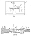
- FIG. 1 An improved circuit breaker 4 in accordance with the present invention is depicted schematically in Fig. 1 .
- the circuit breaker 4 advantageously includes a lockable fastener 6 in accordance with a first embodiment of the present invention.
- the lockable fastener 6 is fastenable to a given level of torque, and is advantageously lockable at the given level of torque to resist loosening as a result of movement of the circuit breaker 4 between an ON position and an OFF or TRIPPED position.
- Each pole 10 of the circuit breaker 4 includes a line conductor 8, a load conductor 12, a pair of fixed contacts 16 (only one of which is depicted), a pair of movable contacts 20 (only one of which is depicted), a pair of arms 24, and one of the lockable fasteners 6.
- a trip unit 28 is in operative connection, directly or indirectly, with the arms 24 of each pole 10 of the circuit breaker 4 to trip the circuit breaker 4 in a known fashion in response to any of a number of predefined circumstances.
- each pole 10 includes a pair of arms 24, and thus also includes pairs of movable and fixed contacts 20 and 16, it will be appreciated that the fastener 6 can be employed in circuit breakers in which each pole includes only a single movable arm.
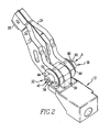
- the load conductor includes a post 30 ( Figs. 2 and 3 ), and the arms 24 are pivotably mounted to the post 30 with the fastener 6.
- the fastener 6 fastens the arms 24 to the post 30 with sufficient force to provide electrically conductive connection between the post 30 and the arms 24 while permitting pivoting movement of the arms 24 with respect to the post 30.
- Each arm 24 includes a hole 26 ( Fig. 3 ) formed therein near one end.
- Each arm also includes a movable contact 20 electrically conductively disposed thereon opposite the hole 26.
- the lockable fastener 6 can generally be stated as including a first member 32, a second member 36, and a locking member 40.
- the depicted exemplary fastener 6 also includes a number of spring washers 44.
- the first member 32 includes a first head 52 and an elongated first axle portion 48.
- the first member 32 includes a cavity 56 formed therein which, in the depicted exemplary first embodiment, extends throughout the longitudinal entirety of the first member 32.
- the cavity 56 includes a first threaded portion 60 and a second threaded portion 64 that are separated from one another with a ledge 68.
- first and second threaded portions can be defined in different fashions.
- the first head 52 includes a first transverse slot 72 formed therein, it being understood that the first head 52 could be of other configurations and could have, for instance, a different tool-appropriate socket instead of the slot 72.
- the first threaded portion 60 is of a first diameter indicated at the numeral 70
- the second threaded portion 64 is of a second diameter indicated at the numeral 74.
- the first diameter 70 is smaller than second diameter 74.
- the ledge 68 extends annularly between the first and second threaded portions 60 and 64 and lies in a plane oriented generally perpendicular to the longitudinal extent of the first axle portion 48. The ledge 68 can therefore be seen to have an inner diameter equal to the first diameter 70 and an outer diameter equal to the second diameter 74.
- first and second diameters could bear a different relationship to one another without departing from the concept of the present invention, such as if the first diameter were greater than the second diameter and the ledge were defined on an open region extending therebetween, or otherwise.
- the second member 36 includes a second head 80, an elongated second axle portion 76, and an elongated shank 84.
- the shank 84 includes a free end 88 opposite the second axle portion 76 and is externally threaded to threadably cooperate with the first threaded portion 60 of the first member 32.
- the second member 36 includes a receptacle 92 formed therein which, in the depicted exemplary embodiment is a cylindrical cavity extending through a portion of the shank 84 from the free end 88 thereof.
- a seat 94 is defined on the receptacle 92 adjacent the free end 88.
- the receptacle 92 can extend greater or lesser distances into the shank 84 from the free end 88, and also can extend into the second axle portion 76 as needed.
- the second head 80 includes a second transverse slot 90 formed therein, it being noted that the second head 80 can also be of a different configuration, as suggested above with respect to the first head 52.
- the locking member 40 includes a threaded body 96 and a taper 98.
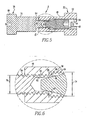
- the body 96 is threadably cooperable with the second threaded portion 64 of the first member 32, and the taper 98 is engageable with the seat 94 of the second member 36, as is indicated in Figs. 5 and 6 .
- a portion of the locking member 40 may be receivable in the receptacle 92 in order to achieve such engagement.
- the exemplary taper 98 is generally in the configuration of a right circular cone and thus has a conic surface oriented at an angle with respect to a longitudinal axis of the locking member 40.
- the angle is about 15°, meaning that the surface-to-surface angle of the taper 98 is about 30°.
- Other angles can be employed for the taper 98, as will be set forth in greater detail below.
- the spring washers 44 are disposed on the first and second axle portions 48 and 76 adjacent the first and second heads 52 and 80.
- the first axle portion 48 is received through one of the holes 26 of one of the arms 24, and the second axle portion 76 is received through the other hole 26 of the other arm 24.
- the first and second axle portions 48 and 76 are then received in a bore 100 ( Fig. 3 ) of the post 30 to fasten the arms 24 to the load conductor 12.
- the shank 84 is received in a first end of the first member 32 and is threadably engaged with the first threaded portion 60.
- the first and second members 32 and 36 are then threadably tightened with respect to one another until a certain level of torque is reached.
- a torque likely will have been selected as providing an optimum or appropriate compromise between the desire to electrically conductively fasten the arms 24 to the post 30 of the load conductor 12 while limiting the rotational friction therebetween.
- the first and second axle portions 48 and 76 will be spaced slightly apart, as is indicated in Fig.5 , so that a compressive loading can be achieved therebetween without interference between the ends of first and second axle portions 48 and 76.
- the first and second heads 52 and 80 compress the spring washers 44, whereby a given compressive force is maintained between the first and second heads 52 and 80. It is known that such spring washers 44 deflect only a relatively small amount in being compressively loaded. Since the various components of the circuit breaker 4 tend to heat up during operation of the circuit breaker 4, and since such heating results in a certain amount of thermal expansion of the aforementioned components, the spring washers 44 help to maintain the level compressive loading between the first and second heads 52 and 80 despite temperature fluctuations.
- the locking member 40 is received in a second, opposite end of the first member 32 into threaded cooperation with the second threaded portion 64.
- the locking member 40 is threadably advanced with an appropriate tool through the second threaded portion 64 until the taper 98 engages the seat 94 of the receptacle 92. In this regard, at least a portion of the taper 98 likely will be received in the receptacle 92.
- the locking member 40 is then tightened in the second threaded portion 64 until an appropriate level of torque is reached between the second threaded portion 64 and the seat 94.
- the body 96 may be formed with an appropriate tool-receiving formation such as a socket opposite the taper 98. In performing the tightening operation the appropriate tool (not shown) would be receivable through the first head into the second threaded portion 64 of the cavity 56 to operably engage the locking member 40.
- the engagement of the taper 98 with the seat 94 causes a portion of the shank 84 to be deformed about the ledge 68.
- Such deformation of the shank 84 advantageously assists in resisting the second member 36 from becoming unthreaded, i.e., loosened, from the first member 32, which helps to retain the lockable fastener 6 at the initially tightened level of torque despite repeated operation of the arms 24 of the circuit breaker 4.
- the deformation of the free end 88 of the shank 84 can be elastic, and additionally can be plastic depending upon the specific needs of the particular application.
- the engagement of the taper 98 with the seat 94 results in a force having both radial and longitudinal components to exist between the taper 98 and the seat 94.
- the radial component of such force is operable both to radially engage the shank 84 with the first threaded portion 60 and to deform the free end 88 of the shank 84 in the fashion indicated in Fig. 6 .
- the longitudinal component of such force longitudinally engages the threads of the shank 84 with the threads of the first threaded portion 60.
- the exemplary locking member 40 may, for example, be torqued to a level of torque on the order of about 30 inch-pounds i.e. about 3,39 newton metre.
- the taper 98 may be configured at different angles to achieve a desirable combination of radial and longitudinal forces on the seat 94.
- the torque to which the locking member 40 is tightened can be varied. For instance, if an alternate embodiment of the lockable fastener 6 employs a shank 84 having a wall thickness greater than that depicted generally in Figs.
- the taper 98 may be at a sharper, i.e., smaller angle and/or the locking member 40 may be tightened to a relatively higher level of torque in order to achieve a desirable combination of forces between the locking member 40, the first member 32, and the second member 36, and to achieve the deformation depicted generally in Fig. 6 .
- the lockable fastener 6 in accordance with the present invention, and the resulting circuit breaker 4 in accordance with the present invention, are configured to provide relatively extended periods of reliability since the lockable fastener 6 can be locked at a given torque setting that is substantially unaffected by operation of the circuit breaker 4.
- the engagement of the locking member 40 between the first and second members 32 and 36 results in radial and longitudinal locking forces to exist between the parts of the fastener 6, and also deforms the second member 36 with respect to the first member 32. These results advantageously resist loosening of the first and second members 32 and 36 with respect to one another.
- the locking member 40 also advantageously performs the locking function without requiring that relatively longer first and second members 32 and 36 be provided.
- the torque setting of the locking member 40 can be readily ascertained on an assembly line, which facilitates assembly of the locking fastener 6 and the resulting circuit breaker 4. Moreover, the locking member 40 is disposed within the interior of the first member 32, so that the fastener 6 occupies a minimal area within the circuit breaker 4. Furthermore, the locking member 40 advantageously locks the first and second members 32 and 36 in a given torque relationship without interfering with such torque.
- a second embodiment of a fastener 106 in accordance with the present invention is depicted generally in Figs. 7 and 8 .
- the fastener 106 can be substituted for the fastener 6 in the circuit breaker 4.
- the fastener 106 includes a first member 132, a second member 136, and a locking member 140.
- first threaded portion 160 and the second threaded portion 164 are defined as being different regions of a single threaded passage 166.
- first and second threaded portions are of the same diameter, and no ledge is disposed therebetween.
- Engagement of a taper 198 of the locking member 140 with a seat 194 of a receptacle 192 of the second member 136 thus performs a locking function without deformation of a portion of the second member 136 about a ledge.
- engagement of the taper 198 with the seat 194 results in both longitudinal and radial forces among the first member 132, the second member 136, and the locking member 140.
- the portion of the second member 136 in the vicinity of the seat 194 is radially engaged with the first threaded portion 160 of the first member 132.
- the threads of the second member 136 are longitudinally engaged with the threads of the first threaded portion 160.
- the fastener 106 thus is lockable by application of the locking member 140 after the first and second member 132 and 136 have been tightened to a specific level of torque. While the locking member does not deform a portion of the second member 136 about a ledge of the first member 132 in the same manner as the fastener 6, it is understood that at least a small degree of deformation of the components of the fastener 106 occurs during locking thereof. The locking member 140 still imparts both radial and longitudinal forces to the second member 136.
Landscapes
- Engineering & Computer Science (AREA)
- General Engineering & Computer Science (AREA)
- Physics & Mathematics (AREA)
- Electromagnetism (AREA)
- Mechanical Engineering (AREA)
- Breakers (AREA)
Claims (16)
- Verriegelbarer Befestiger (6) zum Verbinden einer Vielzahl von Komponenten eines Schaltungsunterbrechers und zum Beibehalten elektrischer Leitfähigkeit zwischen den Komponenten während eine relative Bewegung zwischen den Elementen erlaubt wird, wobei der Befestiger folgendes aufweist:ein erstes Glied (32) mit einem Gewindehohlraum (65) darinnen ausgebildet;ein zweites Glied (36) mit einem Gewindeschaft (84), wobei der Schaft einen Sitz (94) daran angeordnet aufweist, wobei wenigstens ein Teil des Schaftes schraubbar in dem Hohlraum aufnehmbar ist;ein Verriegelungsglied (40), wobei das Verriegelungsglied in Eingriff bringbar ist mit dem Sitz zum Verriegelbaren in Eingriff bringen des Schaftes mit dem ersten Glied; unddas erste Glied, das zweite Glied und das Verriegelungsglied sind axial ausgerichtet, wobei das Verriegelungsglied ein Gewinde aufweist und schraubgewindemäßig mit dem ersten Glied zusammen wirkt,wobei der Gewindehohlraum einen ersten Gewindeteil (60) und einen zweiten Gewindeteil (64) aufweist;wobei der Schaft schraubgewindemäßig in dem ersten Gewindeteil aufnehmbar ist; undwobei das Verriegelungsglied schraubgewindemäßig in dem zweiten Gewindeteil aufnehmbar ist.
- Befestiger nach Anspruch 1, wobei der Gewindehohlraum eine Schulter (68) zwischen den ersten und zweiten Gewindeteilen aufweist.
- Befestiger nach Anspruch 2, wobei sich der Schaft wenigstens teilweise in den zweiten Gewindeteil hinein erstreckt;
wobei wenigstens ein Teil des zweiten Gliedes durch das Verriegelungsglied in Eingriff mit der Schulter verformbar ist. - Befestiger nach Anspruch 3, wobei der erste Gewindeteil einen ersten Durchmesser (70) aufweist; wobei der zweite Gewindeteil einen zweiten Durchmesser (74) aufweist; wobei der erste Durchmesser kleiner ist als der zweite Durchmesser.
- Befestiger nach Anspruch 1, wobei der Sitz eine Aufnahme (92) aufweist;
wobei das Verriegelungsglied eine Verjüngung (98) aufweist; wobei wenigstens ein Teil der Verjüngung in der Aufnahme aufnehmbar ist, wenn das Verriegelungsglied in Eingriff mit dem Sitz steht. - Befestiger nach Anspruch 7, wobei sich der Hohlraum vollständig in Längsrichtung durch das erste Glied hindurch erstreckt;
wobei das zweite Glied durch ein erstes Ende des ersten Gliedes aufnehmbar ist;
wobei das Verriegelungsglied durch ein zweites entgegensetztes Ende des ersten Gliedes aufnehmbar ist. - Befestiger nach Anspruch 6, wobei das erste Glied wenigstens eine erste Federscheibe (44) aufweist.
- Schaltungsunterbrecher (4), der folgendes aufweist:einen Netzleiter (8);einen Lastleiter (12);einen festen Kontakt (16);einen bewegbaren Kontakt (20);einen bewegbaren Arm (24), wobei der bewegbare Kontakt elektrisch leitend an dem Arm angeordnet ist;eine Auslösereinheit (28) die betriebsmäßig mit dem Arm verbunden ist; undein verriegelbarer Befestiger (6) nach Anspruch 1;wobei der feste Kontakt elektrisch leitend an dem Netzleiter oder dem Lastleiter angeordnet ist;wobei der Arm elektrisch leitend und bewegbar an dem anderen Leiter, das heißt dem Lastleiter oder dem Netzleiter mit dem verriegelbaren Befestiger angebracht ist.
- Schaltungsunterbrecher nach Anspruch 8, wobei der Gewindehohlraum eine Schulter (68) aufweist, die zwischen den ersten und zweiten Gewindeteilen angeordnet ist.
- Schaltungsunterbrecher nach Anspruch 9, wobei sich der Schaft wenigstens teilweise in den zweiten Gewindeteil hinein erstreckt; wobei wenigstens ein Teil des zweiten Gliedes durch das Verriegelungsglied verformbar ist und zwar in Eingriff mit der Schulter.
- Schaltungsunterbrecher nach Anspruch 10, wobei der erste Gewindeteil einen ersten Durchmesser (70) aufweist;
wobei der zweite Gewindeteil einen zweiten Durchmesser (74) aufweist; wobei der erste Durchmesser kleiner ist als der zweite Durchmesser. - Schaltungsunterbrecher nach Anspruch 8, wobei die ersten und zweiten Gewindeteile mit dem Äußeren des ersten Gliedes in Verbindung stehen.
- Schaltungsunterbrecher nach Anspruch 8, wobei der Schaft in Längsrichtung und radial verriegelbar mit dem Gewindehohlraum in Eingriff bringbar ist.
- Schaltungsunterbrecher nach Anspruch 8, wobei der Sitz eine Aufnahme (92) aufweist;
wobei das Verriegelungsglied eine Verjüngung (98) aufweist;
wobei wenigstens ein Teil der Verjüngung in der Aufnahme aufnehmbar ist, wenn das Verriegelungsglied in Eingriff mit dem Sitz steht. - Schaltungsunterbrecher nach Anspruch 14, wobei sich der Hohlraum über die gesamte Länge des ersten Gliedes hindurch erstreckt;
wobei das zweite Glied durch ein erstes Ende des ersten Gliedes aufnehmbar ist;
wobei das Verriegelungsglied durch ein zweites entgegensetztes Ende des ersten Gliedes aufnehmbar ist. - Schaltungsunterbrecher nach Anspruch 15, wobei das erste Glied wenigstens eine erste Federscheibe (44) aufweist.
Applications Claiming Priority (2)
| Application Number | Priority Date | Filing Date | Title |
|---|---|---|---|
| US742594 | 2000-12-21 | ||
| US10/742,594 US6878890B1 (en) | 2003-12-19 | 2003-12-19 | Circuit breaker lockable fastener securing a movable contact to its terminal mounting |
Publications (3)
| Publication Number | Publication Date |
|---|---|
| EP1544878A2 EP1544878A2 (de) | 2005-06-22 |
| EP1544878A3 EP1544878A3 (de) | 2007-12-26 |
| EP1544878B1 true EP1544878B1 (de) | 2012-08-29 |
Family
ID=34423519
Family Applications (1)
| Application Number | Title | Priority Date | Filing Date |
|---|---|---|---|
| EP04030031A Expired - Fee Related EP1544878B1 (de) | 2003-12-19 | 2004-12-17 | Verriegelbare Befestigung für Schutzschalter |
Country Status (4)
| Country | Link |
|---|---|
| US (1) | US6878890B1 (de) |
| EP (1) | EP1544878B1 (de) |
| CN (1) | CN100524573C (de) |
| CA (1) | CA2490512A1 (de) |
Cited By (1)
| Publication number | Priority date | Publication date | Assignee | Title |
|---|---|---|---|---|
| US12383316B2 (en) | 2020-07-03 | 2025-08-12 | Osseointegration International B.V. | Locking assembly |
Families Citing this family (11)
| Publication number | Priority date | Publication date | Assignee | Title |
|---|---|---|---|---|
| KR100846277B1 (ko) * | 2005-04-20 | 2008-07-16 | 미쓰비시덴키 가부시키가이샤 | 회로 차단기 |
| US7217895B1 (en) * | 2006-07-06 | 2007-05-15 | Eaton Corporation | Electrical switching apparatus contact assembly and movable contact arm therefor |
| US7387292B1 (en) * | 2007-02-27 | 2008-06-17 | Fisher Controls International, Llc | Apparatus to connect a stem to a valve member |
| US7667150B2 (en) * | 2008-03-04 | 2010-02-23 | Siemens Industry, Inc. | Moveable arm for a circuit breaker and method for making the same |
| DE102008050755A1 (de) * | 2008-10-07 | 2010-04-08 | Siemens Aktiengesellschaft | Elektrisches Gerät mit einem elektrischen Anschluss |
| KR101463043B1 (ko) * | 2009-09-01 | 2014-11-18 | 엘에스산전 주식회사 | 회로차단기의 슬라이드형 가동접촉자 어셈블리 |
| JP5920325B2 (ja) * | 2013-11-11 | 2016-05-18 | 株式会社デンソー | 付勢力調整装置、これを用いた油圧制御弁、及び、付勢力調整装置の製造方法 |
| CN104154096B (zh) * | 2014-08-11 | 2016-01-13 | 青岛大学 | 一种动力电池电极用防松螺栓 |
| CN105590811A (zh) * | 2014-10-23 | 2016-05-18 | 苏州市吴中区欣鑫开关配件厂 | 高压断路器用连接凸缘及其加工方法 |
| CN106449318B (zh) * | 2015-08-04 | 2019-05-24 | 浙江正泰电器股份有限公司 | 断路器脱扣机构 |
| CN107180732A (zh) * | 2017-07-13 | 2017-09-19 | 天津京人电器有限公司 | 一种低压断路器的可动接触装置及低压断路器 |
Family Cites Families (5)
| Publication number | Priority date | Publication date | Assignee | Title |
|---|---|---|---|---|
| US3180963A (en) * | 1962-08-20 | 1965-04-27 | Adalet Mfg Company | High pressure contact for disconnect switch |
| US3201535A (en) * | 1962-12-12 | 1965-08-17 | Westinghouse Electric Corp | Conducting structure and electric switch |
| US5146194A (en) * | 1988-10-12 | 1992-09-08 | Westinghouse Electric Corp. | Screw adjustable clinch joint with bosses |
| US6488459B2 (en) * | 2001-03-07 | 2002-12-03 | Lockheed Martin Corporation | Aerospace fastener |
| US6563407B2 (en) * | 2001-08-21 | 2003-05-13 | Siemens Energy & Automation, Inc. | Pivot joint for a movable contact arm in a molded case circuit breaker |
-
2003
- 2003-12-19 US US10/742,594 patent/US6878890B1/en not_active Expired - Lifetime
-
2004
- 2004-12-17 CA CA002490512A patent/CA2490512A1/en not_active Abandoned
- 2004-12-17 EP EP04030031A patent/EP1544878B1/de not_active Expired - Fee Related
- 2004-12-17 CN CNB2004100954548A patent/CN100524573C/zh not_active Expired - Lifetime
Cited By (1)
| Publication number | Priority date | Publication date | Assignee | Title |
|---|---|---|---|---|
| US12383316B2 (en) | 2020-07-03 | 2025-08-12 | Osseointegration International B.V. | Locking assembly |
Also Published As
| Publication number | Publication date |
|---|---|
| EP1544878A2 (de) | 2005-06-22 |
| CA2490512A1 (en) | 2005-06-19 |
| CN100524573C (zh) | 2009-08-05 |
| EP1544878A3 (de) | 2007-12-26 |
| CN1641817A (zh) | 2005-07-20 |
| US6878890B1 (en) | 2005-04-12 |
Similar Documents
| Publication | Publication Date | Title |
|---|---|---|
| EP1544878B1 (de) | Verriegelbare Befestigung für Schutzschalter | |
| US7416454B2 (en) | Dual size stud electrical connector | |
| US7481684B2 (en) | Z-shaped transformer bar electrical connector | |
| JP5365413B2 (ja) | 回路遮断器 | |
| US10122110B2 (en) | Coupling for power cables | |
| US6583708B1 (en) | Fuse cutout with integrated link break lever and fuse link ejector | |
| US4072393A (en) | Electrical connectors | |
| US7145420B2 (en) | Support structure for a circuit interrupter latch and circuit breaker employing the same | |
| US6462639B1 (en) | Fuse cutout with dome top contact and knurled fuseholder cap | |
| US20150180139A1 (en) | Lug retention arrangement | |
| EP3108494B1 (de) | Schaltanordnung und verbindungsanordnung davon | |
| US6343963B1 (en) | Rotatable and lockable electrical connector | |
| US6739914B2 (en) | Plug connector with central pole | |
| KR100891168B1 (ko) | 누전차단기의 바이메탈 결합구조 | |
| CN101763991A (zh) | 热过载保护装置及双金属触发装置组件 | |
| US6281771B1 (en) | Molded case power switch with secondary cover removably secured by captured rotatable nut | |
| CN104900457B (zh) | 热触发轴及调整双金属元件与热触发轴之间的间距的方法 | |
| US10886642B2 (en) | Mechanical and electrical connection element for the use in low, medium and high voltage | |
| WO2014182276A1 (en) | Lug wire-binding screw | |
| KR100459215B1 (ko) | 배선용 차단기 단자와 압착단자의 접속구조 | |
| US20020063614A1 (en) | Circuit breaker calibration screw | |
| CA2611213C (en) | Dual size stud electrical connector | |
| US7218192B2 (en) | Lockable fastener and circuit breaker employing the same | |
| JP5245458B2 (ja) | 端子台構造とこれを備えたスイッチ | |
| CN220041754U (zh) | 漏电断路器壳体结构及断路器 |
Legal Events
| Date | Code | Title | Description |
|---|---|---|---|
| PUAI | Public reference made under article 153(3) epc to a published international application that has entered the european phase |
Free format text: ORIGINAL CODE: 0009012 |
|
| AK | Designated contracting states |
Kind code of ref document: A2 Designated state(s): AT BE BG CH CY CZ DE DK EE ES FI FR GB GR HU IE IS IT LI LT LU MC NL PL PT RO SE SI SK TR |
|
| AX | Request for extension of the european patent |
Extension state: AL BA HR LV MK YU |
|
| PUAL | Search report despatched |
Free format text: ORIGINAL CODE: 0009013 |
|
| AK | Designated contracting states |
Kind code of ref document: A3 Designated state(s): AT BE BG CH CY CZ DE DK EE ES FI FR GB GR HU IE IS IT LI LT LU MC NL PL PT RO SE SI SK TR |
|
| AX | Request for extension of the european patent |
Extension state: AL BA HR LV MK YU |
|
| 17P | Request for examination filed |
Effective date: 20080320 |
|
| AKX | Designation fees paid |
Designated state(s): FR GB NL |
|
| REG | Reference to a national code |
Ref country code: DE Ref legal event code: 8566 |
|
| 17Q | First examination report despatched |
Effective date: 20110118 |
|
| GRAP | Despatch of communication of intention to grant a patent |
Free format text: ORIGINAL CODE: EPIDOSNIGR1 |
|
| GRAS | Grant fee paid |
Free format text: ORIGINAL CODE: EPIDOSNIGR3 |
|
| GRAA | (expected) grant |
Free format text: ORIGINAL CODE: 0009210 |
|
| AK | Designated contracting states |
Kind code of ref document: B1 Designated state(s): FR GB NL |
|
| REG | Reference to a national code |
Ref country code: GB Ref legal event code: FG4D |
|
| REG | Reference to a national code |
Ref country code: NL Ref legal event code: T3 |
|
| PLBE | No opposition filed within time limit |
Free format text: ORIGINAL CODE: 0009261 |
|
| STAA | Information on the status of an ep patent application or granted ep patent |
Free format text: STATUS: NO OPPOSITION FILED WITHIN TIME LIMIT |
|
| REG | Reference to a national code |
Ref country code: NL Ref legal event code: V1 Effective date: 20130701 |
|
| 26N | No opposition filed |
Effective date: 20130530 |
|
| GBPC | Gb: european patent ceased through non-payment of renewal fee |
Effective date: 20121217 |
|
| REG | Reference to a national code |
Ref country code: FR Ref legal event code: ST Effective date: 20130830 |
|
| PG25 | Lapsed in a contracting state [announced via postgrant information from national office to epo] |
Ref country code: NL Free format text: LAPSE BECAUSE OF NON-PAYMENT OF DUE FEES Effective date: 20130701 |
|
| PG25 | Lapsed in a contracting state [announced via postgrant information from national office to epo] |
Ref country code: FR Free format text: LAPSE BECAUSE OF NON-PAYMENT OF DUE FEES Effective date: 20130102 Ref country code: GB Free format text: LAPSE BECAUSE OF NON-PAYMENT OF DUE FEES Effective date: 20121217 |