EP1544810A2 - Diebstahlsicherungsvorrichtung - Google Patents
Diebstahlsicherungsvorrichtung Download PDFInfo
- Publication number
- EP1544810A2 EP1544810A2 EP04257755A EP04257755A EP1544810A2 EP 1544810 A2 EP1544810 A2 EP 1544810A2 EP 04257755 A EP04257755 A EP 04257755A EP 04257755 A EP04257755 A EP 04257755A EP 1544810 A2 EP1544810 A2 EP 1544810A2
- Authority
- EP
- European Patent Office
- Prior art keywords
- supporting frame
- cross member
- bolts
- holes
- levelling
- Prior art date
- Legal status (The legal status is an assumption and is not a legal conclusion. Google has not performed a legal analysis and makes no representation as to the accuracy of the status listed.)
- Withdrawn
Links
Images


Classifications
-
- G—PHYSICS
- G07—CHECKING-DEVICES
- G07F—COIN-FREED OR LIKE APPARATUS
- G07F19/00—Complete banking systems; Coded card-freed arrangements adapted for dispensing or receiving monies or the like and posting such transactions to existing accounts, e.g. automatic teller machines
- G07F19/20—Automatic teller machines [ATMs]
- G07F19/201—Accessories of ATMs
-
- F—MECHANICAL ENGINEERING; LIGHTING; HEATING; WEAPONS; BLASTING
- F16—ENGINEERING ELEMENTS AND UNITS; GENERAL MEASURES FOR PRODUCING AND MAINTAINING EFFECTIVE FUNCTIONING OF MACHINES OR INSTALLATIONS; THERMAL INSULATION IN GENERAL
- F16B—DEVICES FOR FASTENING OR SECURING CONSTRUCTIONAL ELEMENTS OR MACHINE PARTS TOGETHER, e.g. NAILS, BOLTS, CIRCLIPS, CLAMPS, CLIPS OR WEDGES; JOINTS OR JOINTING
- F16B37/00—Nuts or like thread-engaging members
- F16B37/04—Devices for fastening nuts to surfaces, e.g. sheets, plates
-
- G—PHYSICS
- G07—CHECKING-DEVICES
- G07F—COIN-FREED OR LIKE APPARATUS
- G07F19/00—Complete banking systems; Coded card-freed arrangements adapted for dispensing or receiving monies or the like and posting such transactions to existing accounts, e.g. automatic teller machines
- G07F19/20—Automatic teller machines [ATMs]
-
- G—PHYSICS
- G07—CHECKING-DEVICES
- G07F—COIN-FREED OR LIKE APPARATUS
- G07F19/00—Complete banking systems; Coded card-freed arrangements adapted for dispensing or receiving monies or the like and posting such transactions to existing accounts, e.g. automatic teller machines
- G07F19/20—Automatic teller machines [ATMs]
- G07F19/205—Housing aspects of ATMs
Definitions
- the present invention relates to an anti-theft device which is particularly suited for use with automated teller machines (A.T.M.s).
- the A.T.M. is attached to the anti-theft device using bolts which pass through the base of the A.T.M. and engage nuts which are welded to the anti-theft device.
- the A.T.M. must be located accurately on the anti-theft device to align the bolt holes in the A.T.M. with the nuts on the anti-theft device. This is easier said than done as an A.T.M. typically weighs in excess of one tonne which makes it difficult to move the A.T.M. once lowered onto the supporting frame.
- the A.T.M. is level, particularly as an A.T.M. must often be aligned with another object, for example a hole in a wall, through which the A.T.M. is accessed by a user.
- the bolts passing through the upright walls of the brackets must be loosened, the cross members repositioned and the bolts tightened. This can not be done when the A.T.M. has been placed on the anti-theft device as if a bolt is loosened the A.T.M. will drop. This can be inconvenient, particularly if after placing the A.T.M. on the anti-theft device it is found that the A.T.M. is not level, despite best efforts to level the cross members prior to placement of the A.T.M.
- a first aspect of the present invention provides a supporting frame for an A.T.M., the supporting frame comprising a cross member which is secured to a floor and securing means for securing the A.T.M. to the cross member, the securing means comprising a plurality of nuts and bolts, each nut being attached to the cross member and movable relative to the cross member.
- the nut is held in a cage which is attached to the cross member by attaching means.
- the attaching means comprises a clip which can fit around the cross member.
- the clip and cage are integrated.
- the clip and cage are formed from a single piece of material.
- each nut is located below the cross member and accessed by the bolt through a hole in the cross member.
- a second aspect of the present invention provides a supporting frame for an automated teller machine, the supporting frame comprising levelling means for levelling an A.T.M. which is placed on the supporting frame.
- the levelling means comprises a plurality of bolts which are screwed into the supporting frame and which can be turned to raise or lower the A.T.M.
- a plate is provided between the bolts and the A.T.M. upon which the A.T.M. rests.
- a third aspect of the present invention provides a method of installing an A.T.M., the method comprising providing a supporting frame for the A.T.M., the supporting frame comprising levelling means, securing the supporting frame to a floor, placing the A.T.M. on top of the supporting frame, levelling the A.T.M. by adjusting the levelling means and securing the A.T.M. to the supporting frame.
- the levelling means comprises a plurality of bolts which are screwed into the supporting frame, wherein levelling is performed by turning one or more of the bolts to raise or lower the A.T.M.
- the A.T.M. is secured to the supporting frame by placing bolts through holes in a base of the A.T.M. and through holes in the top of the supporting frame to engage nuts which are attached to the supporting frame, wherein when placing the A.T.M. on the supporting frame, it is not necessary to accurately align the holes in the base of the A.T.M. with the holes in the top of the supporting frame.
- a further aspect of the present invention provides a supporting frame for an A.T.M., the supporting frame comprising a beam which is securable to a floor and securing means for attaching the A.T.M. to the beam, the securing means comprising first and second fixing members, the first member being movably mounted on the beam and the second member, in use, passing through an aperture in a floor of the A.T.M., whereby the first member is movable into alignment with the aperture to enable the first and second members to be coupled together to secure the A.T.M. to the beam.
- a further aspect of the present invention provides a supporting frame for an A.T.M., the supporting frame comprising a plate on which the A.T.M. sits in use, and a beam to which the A.T.M. is attached, wherein the plate is adjustably supported on the beam by adjustment means which is accessible for adjustment when the A.T.M. is on the plate.
- Figure 1 shows an anti-theft device 1 forming an embodiment of the present invention. It can be seen that the anti-theft device 1 has a low profile, which inhibits the leverage that can be applied to an A.T.M. fitted to the anti-theft device in an attempted theft.
- the anti-theft device 1 is preferably available in a number of variants of different height, the height of each variant being adjustable over a specified height range.
- the variants preferably have height ranges of 75-110mm, 110-185mm, 185-300mm and 300-500mm, the choice of variant being determined by factors such as the height of the A.T.M. and the height of the surface on which the anti-theft device is mounted relative to street level.
- the lid 3 of the anti-theft device 1 is in place and most of the components are obscured from view, but will be shown in the following figures.
- An A.T.M. can be attached to the anti-theft device 1 by means of four safe bolts 5 which are fed through holes in the base of the A.T.M. and through holes 7 in the lid 3 of the anti-theft device 1.
- the anti-theft device 1 When the anti-theft device 1 is installed, it is fitted as a single unit as shown in this figure, with the exception of the four bolts 5 which are removed prior to placing the A.T.M. onto the lid 3 of the anti-theft device 1.
- Six access holes 9 are located in the lid 3 of the anti-theft device 1, through which expanding bolts 85 are inserted to attach the anti-theft device 1 to the ground 87, as shown in Figure 10.
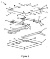
- FIG. 2 is a partially exploded perspective view of the embodiment of Figure 1.
- the anti-theft device 1 is comprised of a base frame 11, two brackets 13, two cross member assemblies 15 and a lid 3.
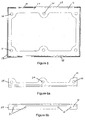
- a top view of the base frame 11 is shown in Figure 5.
- the base frame 11 is rectangular and has a bottom portion 17 and four peripheral flanges 19.
- the four peripheral flanges 19 project upwards from the bottom portion 17 an equal amount.
- the base frame 11 is formed from 8mm mild steel sheet by cutting the appropriate shape and folding the four edges to form the four peripheral flanges 19.
- Bracket 13 A top view and a side view of a bracket 13 are shown in Figures 6a and 6b respectively.
- Each bracket 13 has a bottom portion 25 and a side portion 27.
- the brackets 13 are formed by cutting and folding 10mm mild steel.
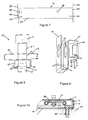
- FIG. 7 A top view of a cross member beam 16 is shown in Figure 7.
- the cross member beam 16 is comprised of a cross member 33 and two end plates 35.
- Two captive nut assemblies 37 and two adjustment bolts 45 are fitted to each cross member beam 16 to form a cross member assembly 15.
- the cross member 33 is made of 20mm mild steel.
- the end plates 35 are welded to the ends 39 of the cross member 33.
- There are two holes 41 in each end plate 35 which align with the holes 31 in the side portion 27 of the brackets 13.
- An adjustment bolt hole 46 and a safe bolt hole 38 are located towards each end 39 of the cross member 33.
- the adjustment bolt hole 46 is threaded, so that as the adjustment bolt 45 is turned, it moves into or out of the cross member 33.
- the captive nut assembly 37 is comprised of a bent plate 47 and a nut 49.
- a side view of the captive nut assembly 37 and safe bolt 5 is shown in Figure 8 and a perspective view of the bent plate 47 is shown in Figure 9.
- the bent plate 47 is bent into an 's' shape to form a cage portion 55 and a clip portion 61.
- the end 51 of the bent plate 47 forming the cage portion 55 is further bent inwards on three sides to form lips 53.
- the nut 49 is loosely held within the cage 55 formed by the lips 53 and the 'u' shaped portion 57 of the end 51 of the bent plate 47, so that limited movement of the nut 49 relative to the bent plate 47 is possible, without the nut 49 becoming separated from the bent plate 47 and without the nut 49 being able to rotate within the cage portion 55.
- the other end 59 of the bent plate 47 forms a second 'u' shaped clip portion 61.
- the cross member 33 slides into the clip portion 61 of the bent plate 47, the depth d of the clip 61 being substantially the same as the thickness, 20mm, of the cross member 33, so that the holes 63 in the bent plate 47 are aligned with the safe bolt hole 38 in the cross member 33.
- the bent plate 47 is typically made from a single piece of metal, but other material such as a polymer may be used.
- the lid 3 is comprised of a top portion 69 and four peripheral flanges 71.
- the lid 3 is made from 8mm mild steel.
- the lid 3 fits on top of the base frame 11 so that the peripheral flanges 71 of the lid 3 overlap the peripheral flanges 19 of the base frame 11.
- There are six holes 9 in the top portion 69 of the lid 3 which are aligned with the holes 21 in the bottom portion 17 of the base frame 11.
- the cross member assemblies 15 are attached with eight bolts 43 to the two brackets 13, the bolts 43 passing through the holes 41 in the end plates 35 and the holes 31 in the side portion 27 of the brackets 13.
- the brackets 13 are placed into the base frame 11, the holes 29 in the bottom portion 25 of the brackets 13 being aligned with the holes 21 in the bottom portion 17 of the base frame 11.
- Four adjustment bolts 45 are inserted into the adjustment bolt holes 46.
- the lid 3 is placed on the base frame 11.
- peripheral flanges 71 of the lid 3 overlap the peripheral flanges 19 of the base frame 11 to provide additional protection to the side of the anti-theft device 1 in the event of attack by a fork lift truck, for example.
- Expanding bolts 85 are inserted through the six holes 9 in the top portion 69 of the lid 3 to attach the brackets 13 and base frame 11 to the floor 87, as shown in Figure 10.
- An A.T.M. is lowered onto the lid 3 of the anti-theft device 1. Holes in the base of the A.T.M. are aligned with the four holes 7 in the lid 3 of the anti-theft device 1. It is not necessary to accurately align the holes as will be explained below.
- the A.T.M. is levelled by turning one or more of the four adjustment bolts 45 to lift or lower the lid 3, as required. The adjustment bolts 45 are accessed via the slots 77 in the sides 81 of the lid 3 as shown in Figure 4. Levelling the A.T.M. in this manner can be done when the A.T.M. is on top of the anti-theft device 1.
- the four safe bolts 5 are inserted through holes in the base of the A.T.M. to pass through the four holes 7 in the lid 3 of the anti-theft device 1 and to pass through the four holes 38 in the cross member 33.
- the holes 7, 38 in the lid 3 and in the cross member 33 are significantly larger than the diameter of the shaft 67 of the safe bolt 5, to allow lateral movement of the safe bolt 5 and the captive nut assembly 37 when aligning the safe bolt 5 with the nut 49.
- the safe bolts 5 engage the nuts 49 which are loosely held within the captive nut assembly 37. As the nuts 49 have a limited degree of movement, it is not necessary to accurately align the holes in the base of the A.T.M. with the holes 7 in the lid 3 of the anti-theft device 1, which greatly eases installation of the A.T.M. on the anti-theft device 1.
Landscapes
- Engineering & Computer Science (AREA)
- General Engineering & Computer Science (AREA)
- Business, Economics & Management (AREA)
- Accounting & Taxation (AREA)
- Finance (AREA)
- Physics & Mathematics (AREA)
- General Physics & Mathematics (AREA)
- Mechanical Engineering (AREA)
- Casings For Electric Apparatus (AREA)
- Connection Of Plates (AREA)
- Automobile Manufacture Line, Endless Track Vehicle, Trailer (AREA)
Applications Claiming Priority (2)
| Application Number | Priority Date | Filing Date | Title |
|---|---|---|---|
| GB0329337A GB2409252B (en) | 2003-12-18 | 2003-12-18 | Anti-theft device |
| GB0329337 | 2003-12-18 |
Publications (2)
| Publication Number | Publication Date |
|---|---|
| EP1544810A2 true EP1544810A2 (de) | 2005-06-22 |
| EP1544810A3 EP1544810A3 (de) | 2007-08-08 |
Family
ID=30471304
Family Applications (1)
| Application Number | Title | Priority Date | Filing Date |
|---|---|---|---|
| EP04257755A Withdrawn EP1544810A3 (de) | 2003-12-18 | 2004-12-14 | Diebstahlsicherungsvorrichtung |
Country Status (2)
| Country | Link |
|---|---|
| EP (1) | EP1544810A3 (de) |
| GB (1) | GB2409252B (de) |
Cited By (6)
| Publication number | Priority date | Publication date | Assignee | Title |
|---|---|---|---|---|
| WO2009003254A1 (en) * | 2007-06-29 | 2009-01-08 | Tecnologia Bancaria S.A. | Anchoring base for fixing banking equipments |
| ES2326953A1 (es) * | 2009-04-14 | 2009-10-21 | Luis Leal Pascual | Bancada cerrada regulable en altura y nivelacion para cajeros automaticos, dispensadores de efectivo y similares. |
| ES2344394A1 (es) * | 2008-10-29 | 2010-08-25 | Primanos, S.L | Bancada para fijacion al suelo de maquinas pesadas. |
| ES2356951A1 (es) * | 2009-03-12 | 2011-04-14 | Tecnoexpress S.L.U. | Peana de elevación y soporte aplicable para máquinas expendedoras de dinero y/o cajas fuertes. |
| ITMI20111659A1 (it) * | 2011-09-15 | 2013-03-16 | Stefano Cantoni | Sistema di protezione perfezionato di mobili per dispositivi automatici di transazioni commerciali. |
| ES2624537A1 (es) * | 2016-01-14 | 2017-07-14 | Primanos S.L. | Adicion a la patente p200803073 bancada para fijacion al suelo de maquinas pesadas |
Family Cites Families (10)
| Publication number | Priority date | Publication date | Assignee | Title |
|---|---|---|---|---|
| GB368507A (en) * | 1931-02-25 | 1932-03-10 | Chatwood Safe Company Ltd | Improvements relating to foundation plates for safes and the like |
| GB1218264A (en) * | 1968-10-09 | 1971-01-06 | Inst Regelungstechnik | Insert element for the securing of component units to appliance rails |
| US4739637A (en) * | 1984-05-14 | 1988-04-26 | Vaultec Industries, Inc. | Locking device for portable equipment |
| DE3637705A1 (de) * | 1986-11-05 | 1988-05-19 | Raymond A Fa | Halteklammer fuer mutter mit unterlegscheibe |
| GB8708893D0 (en) * | 1987-04-14 | 1987-05-20 | Thompson J | Security devices for safes |
| JPH05172299A (ja) * | 1991-12-25 | 1993-07-09 | N I Shi Oototetsuku Kk | 構造材 |
| FR2711196B1 (fr) * | 1993-10-13 | 1995-11-24 | Rapid Sa | Ecrou encagé à montage sur un rail ou analogue et assemblage obtenu à l'aide de cet écrou. |
| GB9507255D0 (en) * | 1995-04-07 | 1995-05-31 | Acketts Group Ltd | Anti-theft device |
| DE19821646B4 (de) * | 1998-05-14 | 2005-06-16 | ZF Lemförder Metallwaren AG | Befestigungssystem |
| GB2366325B (en) * | 2000-08-30 | 2004-07-21 | Acketts Group Ltd | Anti-theft device |
-
2003
- 2003-12-18 GB GB0329337A patent/GB2409252B/en not_active Expired - Lifetime
-
2004
- 2004-12-14 EP EP04257755A patent/EP1544810A3/de not_active Withdrawn
Cited By (8)
| Publication number | Priority date | Publication date | Assignee | Title |
|---|---|---|---|---|
| WO2009003254A1 (en) * | 2007-06-29 | 2009-01-08 | Tecnologia Bancaria S.A. | Anchoring base for fixing banking equipments |
| ES2344394A1 (es) * | 2008-10-29 | 2010-08-25 | Primanos, S.L | Bancada para fijacion al suelo de maquinas pesadas. |
| ES2344394B1 (es) * | 2008-10-29 | 2011-05-09 | Primanos, S.L | Bancada para fijacion al suelo de maquinas pesadas. |
| ES2356951A1 (es) * | 2009-03-12 | 2011-04-14 | Tecnoexpress S.L.U. | Peana de elevación y soporte aplicable para máquinas expendedoras de dinero y/o cajas fuertes. |
| ES2326953A1 (es) * | 2009-04-14 | 2009-10-21 | Luis Leal Pascual | Bancada cerrada regulable en altura y nivelacion para cajeros automaticos, dispensadores de efectivo y similares. |
| ES2326953B1 (es) * | 2009-04-14 | 2010-07-15 | Luis Leal Pascual | Bancada cerrada regulable en altura y nivelacion para cajeros automaticos, dispensadores de efectivo y similares. |
| ITMI20111659A1 (it) * | 2011-09-15 | 2013-03-16 | Stefano Cantoni | Sistema di protezione perfezionato di mobili per dispositivi automatici di transazioni commerciali. |
| ES2624537A1 (es) * | 2016-01-14 | 2017-07-14 | Primanos S.L. | Adicion a la patente p200803073 bancada para fijacion al suelo de maquinas pesadas |
Also Published As
| Publication number | Publication date |
|---|---|
| GB2409252A (en) | 2005-06-22 |
| EP1544810A3 (de) | 2007-08-08 |
| GB2409252B (en) | 2007-03-21 |
| GB0329337D0 (en) | 2004-01-21 |
Similar Documents
| Publication | Publication Date | Title |
|---|---|---|
| CA2228070C (en) | Anchor for guard rail system on structural grating floors | |
| US5538206A (en) | Sink support | |
| CA2626577C (en) | Curb box cover assembly | |
| CA2595842C (en) | A pedestal head | |
| US6321928B1 (en) | Enclosure mounting pad with support base | |
| EP1544810A2 (de) | Diebstahlsicherungsvorrichtung | |
| US5167040A (en) | Mounting frame for the pre-wall installation of a sanitary fixture | |
| US20190119940A1 (en) | Laterally adjustable post base assembly | |
| WO2016178016A1 (en) | Fixing for a balcony | |
| GB2268541A (en) | Anti-theft device. | |
| US5271195A (en) | Adjustable grate | |
| US4862992A (en) | Noise barrier | |
| US5611640A (en) | Method and apparatus for anchoring a utility grate cover | |
| JP2002294853A (ja) | 排水桝 | |
| US5025607A (en) | Apparatus to aid in the installation of doors | |
| GB2299619A (en) | Anti-theft device for ATM | |
| EP1184819B1 (de) | Diebstahlsicherungsvorrichtung | |
| US7077598B1 (en) | Bollard and method of mounting | |
| EP2217861B1 (de) | Gaskochfeld | |
| JP3247327B2 (ja) | マンホール枠における落下防止網の取付構造 | |
| WO2010023031A1 (en) | Supporting device for covering slabs | |
| JP3555715B2 (ja) | 外壁パネルの支持構造 | |
| AU2020210177B2 (en) | Apparatus and method for installing a kerb rail on an access ramp | |
| AU2017100895A4 (en) | Construction Support System and Support Bracket | |
| JP2024003713A (ja) | 天秤台 |
Legal Events
| Date | Code | Title | Description |
|---|---|---|---|
| PUAI | Public reference made under article 153(3) epc to a published international application that has entered the european phase |
Free format text: ORIGINAL CODE: 0009012 |
|
| AK | Designated contracting states |
Kind code of ref document: A2 Designated state(s): AT BE BG CH CY CZ DE DK EE ES FI FR GB GR HU IE IS IT LI LT LU MC NL PL PT RO SE SI SK TR |
|
| AX | Request for extension of the european patent |
Extension state: AL BA HR LV MK YU |
|
| PUAL | Search report despatched |
Free format text: ORIGINAL CODE: 0009013 |
|
| AK | Designated contracting states |
Kind code of ref document: A3 Designated state(s): AT BE BG CH CY CZ DE DK EE ES FI FR GB GR HU IE IS IT LI LT LU MC NL PL PT RO SE SI SK TR |
|
| AX | Request for extension of the european patent |
Extension state: AL BA HR LV MK YU |
|
| AKX | Designation fees paid | ||
| REG | Reference to a national code |
Ref country code: DE Ref legal event code: 8566 |
|
| STAA | Information on the status of an ep patent application or granted ep patent |
Free format text: STATUS: THE APPLICATION IS DEEMED TO BE WITHDRAWN |
|
| 18D | Application deemed to be withdrawn |
Effective date: 20080209 |