EP1544698A1 - Vorrichtung und Verfahren zur Kontrolle eines Bordnetzes - Google Patents
Vorrichtung und Verfahren zur Kontrolle eines Bordnetzes Download PDFInfo
- Publication number
- EP1544698A1 EP1544698A1 EP03104858A EP03104858A EP1544698A1 EP 1544698 A1 EP1544698 A1 EP 1544698A1 EP 03104858 A EP03104858 A EP 03104858A EP 03104858 A EP03104858 A EP 03104858A EP 1544698 A1 EP1544698 A1 EP 1544698A1
- Authority
- EP
- European Patent Office
- Prior art keywords
- electrical system
- prediction
- current
- motor vehicle
- parameter
- Prior art date
- Legal status (The legal status is an assumption and is not a legal conclusion. Google has not performed a legal analysis and makes no representation as to the accuracy of the status listed.)
- Granted
Links
Images


Classifications
-
- B—PERFORMING OPERATIONS; TRANSPORTING
- B60—VEHICLES IN GENERAL
- B60R—VEHICLES, VEHICLE FITTINGS, OR VEHICLE PARTS, NOT OTHERWISE PROVIDED FOR
- B60R16/00—Electric or fluid circuits specially adapted for vehicles and not otherwise provided for; Arrangement of elements of electric or fluid circuits specially adapted for vehicles and not otherwise provided for
- B60R16/02—Electric or fluid circuits specially adapted for vehicles and not otherwise provided for; Arrangement of elements of electric or fluid circuits specially adapted for vehicles and not otherwise provided for electric constitutive elements
- B60R16/023—Electric or fluid circuits specially adapted for vehicles and not otherwise provided for; Arrangement of elements of electric or fluid circuits specially adapted for vehicles and not otherwise provided for electric constitutive elements for transmission of signals between vehicle parts or subsystems
-
- B—PERFORMING OPERATIONS; TRANSPORTING
- B62—LAND VEHICLES FOR TRAVELLING OTHERWISE THAN ON RAILS
- B62D—MOTOR VEHICLES; TRAILERS
- B62D5/00—Power-assisted or power-driven steering
- B62D5/04—Power-assisted or power-driven steering electrical, e.g. using an electric servo-motor connected to, or forming part of, the steering gear
- B62D5/0457—Power-assisted or power-driven steering electrical, e.g. using an electric servo-motor connected to, or forming part of, the steering gear characterised by control features of the drive means as such
- B62D5/0481—Power-assisted or power-driven steering electrical, e.g. using an electric servo-motor connected to, or forming part of, the steering gear characterised by control features of the drive means as such monitoring the steering system, e.g. failures
Definitions
- the invention relates to a method for predicting a future load condition in the electrical system of a motor vehicle and a method and a device to control the electrical system of a motor vehicle.
- Modern motor vehicles are characterized by an increasing number of electrical and Electronic devices characterized by the electrical system of the motor vehicle to be supplied with energy.
- Consumers such as an electric power steering system - often cause problems, since these briefly high load peaks in the electrical system which exceed the current capacity of the vehicle electrical system.
- the object of the present invention was therefore to provide means with where possible the functionality of the electrical system of a motor vehicle can be guaranteed.
- the method enables the prediction of future loads on the electrical system based on currently measured parameter vectors, wherein the predictive model is obtained empirically from example data. It is not necessary functional relationships between operating parameters of the motor vehicle and to know or analyze future power consumption. such Rather, relationships are determined by an adaptation procedure from the example data extracted and into a prediction zone subdivision of the parameter space implemented. The predictions about the Future stress can be used to advantage in one To counteract exceeding the capacity limits of the electrical system and thereby ensuring a continuous functioning of the network.
- a load condition of the electrical system can thereby be defined that within a given future period of time Current flow in the electrical system or in a particular consumer on the electrical system at least temporarily in a predetermined interval. For example, you can by specifying the current interval [ ⁇ , ⁇ [exactly two load states distinguished namely, the remaining of the current below the threshold ⁇ or exceeding this threshold within the next ⁇ seconds after the time considered. By specifying several such thresholds In principle, any number of load states can be differentiated.
- the selection of the operating parameters of the motor vehicle which is a parameter vector define is preferably in terms of application-specific Special features and known or suspected functional relationships of Operating parameters and load conditions in the electrical system.
- the parameter vector at least one of the following enumerated variables and / or at least one (single or multiple) time derivative thereof: the current flow in the electrical system or in a specific consumer on the electrical system; the rate of change of the current flow in the electrical system or in a particular consumer at the electrical system; the vehicle speed; the steering angle and / or the rate of change of the steering angle, these variables in particular with regard to on power peaks of electric steering assistance are of importance; the accelerator pedal position; Road parameters such as upcoming branches, Gradients or turns, with the road parameters of one Navigation system can be provided; the state of the flashing system for Direction indicator, this size to indicate upcoming steering maneuvers may be significant.
- a prediction zone can Statistical characteristics of the respectively associated subset of the example data be characterized or defined. Belonging to a prediction zone "Subset of the sample data "includes all sample data, their load status corresponds to the load state associated with the prediction zone. In other words, the total amount of all sample data becomes subsets divided, each characterized by a specific load condition and within the subsets then become statistical parameters to define corresponding prediction zones.
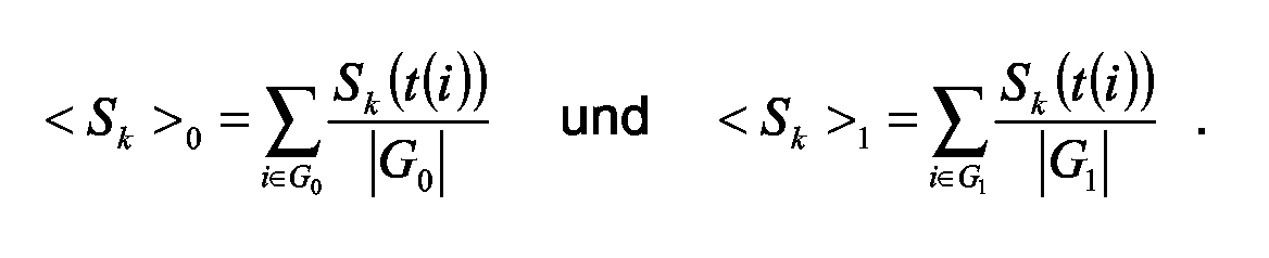
- the above-mentioned statistical parameters may around the mean ⁇ and the covariance matrix ⁇ of all parameter vectors of the each subset.
- the mean value describes a characteristic or substitute point of the respective subset while the Covariance correlations detected between the components of the parameter vectors.
- the above-mentioned statistical characteristics of the mean value and the covariance can be used in particular as follows for the definition of the prediction zones or for the assignment of a current parameter vector S (t):
- An (arbitrary or current) parameter vector S is assigned to that prediction zone to which it is assigned has the shortest Mahalanobis distance, where the Mahalano-bis distance is defined as the size ( S- ⁇ ) T ⁇ -1 ( S- ⁇ ).
- the Mahalano-bis distance is defined as the size ( S- ⁇ ) T ⁇ -1 ( S- ⁇ ).
- the extraction of sample data required for step a) of the method and the division of the space of the parameter vectors into prediction zones can separately, d. H. uniform and driver-independent for a large number of vehicles respectively. Preferably, however, it takes place during the driving operation of a motor vehicle, so that the example data specific to the individual motor vehicle and the driver and, if necessary, also adapt to changes over time can.
- the process can be specific by reducing the power consumption Consumers and by increasing the power supply, that impending load peaks do not lead to an overload of the Lead electrical system.
- the invention further relates to a device for controlling the electrical system of a Motor vehicle, which is adapted to a method of the above to explain explained type.
- the device can in particular by a Data processing device (microcontroller, etc.) can be realized, which with corresponding signal inputs for detecting a parameter vector and possibly with control outputs for controlling the power consumption of Consumers or the output of generators.
- a Data processing device microcontroller, etc.
- the electrical system controlled by the device can in particular be an electrical Steering assist system, an electric compressor for the internal combustion engine and / or a fan for the internal combustion engine included. at these components are devices that are consumed by a consumer are marked with load peaks, so that a forward-looking Management of the electrical system is particularly important for this.
- Figure 1 shows a typical time course of the current consumption I of an electrical Power Assisted Steering System (EPAS) Motor vehicle. While the averaged over the travel time power consumption such a system is relatively small, the course shows again very short current peaks of up to 100 A Such current peaks can for the stability of the electrical system of the motor vehicle represent a problem. Therefore, in the present case, a method is proposed in which based on a statistical pattern recognition in advance situations are detected in which a steering assistance system or another system like For example, an electrically driven diesel compressor (EDC) or a fan motor lead to an internal combustion engine for current peaks. Based on This prediction can then be a control device for the electrical system accordingly respond to an exceeding of the capacities of the electrical system and to avoid high fluctuations of the voltage.
- EDC electrically driven diesel compressor
- control device doing so the power consumption of less critical consumers like For example, reduce, delay or delay heaters for a short time switch off.
- control device and the power supply through a generator (alternator, etc.) drive up to the deployment to guarantee sufficient performance.
- a (future) load state of the vehicle electrical system is represented as an (EPAS) current peak of more than ⁇ A within the next ⁇ seconds, ie in the time interval [t, t + ⁇ ], defined.
- the first component S 1 (t) of the parameter vector should be the instantaneous value of the EPAS current flow.
- FIG. 3 shows the correct prediction function (lower bar) for test data of the current profile I analogous to FIG. 2, as well as the prediction of a calculated prediction function CPD ⁇ , ⁇ (upper bar). Deviations between the two bars represent the prediction errors and therefore contribute to the percentages p 01 and p 10, respectively. These percentages can be used as the first quality measure for the calculated predictive function.
- E 2 can be regarded as the error rate, the minimization of which is more important since it corresponds to the undetected and thus untreated current peaks, while the errors underlying E 1 can "only" lead to superfluous control actions in the electrical system.
- measurement data obtained from nine different (non-professional) drivers in real driving situations was used.
- the drivers covered a total distance of 326 km in a total driving time of 12:46 hours.
- S 2 Vehicle speed [km / h]
- S 3 Steering angle [degrees]
- S 4 Steering angle rate [degrees / s].
- T denotes the transposition of a vector and "-1" the inversion of a vector Matrix.
- the described algorithm can be implemented quickly and easily.
- the influence of the quantities ⁇ and ⁇ , which define the load state, is indirect because it influences the division of the example data into the sub-sets G 0 and G 1 and thus the statistical parameters derived therefrom.
- FIG. 4 shows in this respect a typical distribution of two components S i , S k of the parameter vectors of example data (crosses). Immediately recognizable is that the sample data is distributed over two clusters which correspond to subsets G 0 (no subsequent load condition observed) and G 1 (subsequent load condition observed). Because a correlation of the vector components S i, S k, the cluster have an elongated shape, respectively, wherein the mean values ⁇ 0 and ⁇ 1 in the center of the cluster G 0 and G 1 are.
- the "Mahalanobis decision boundary" is entered as a dashed line, which divides the parameter plane into the two prediction zones (half planes) V 0 and V 1 and which lies exactly between said axes, which greatly prevents misclassifications. Points lying on the decision boundary itself can, for example, be assigned to the zone V 0 by definition.
- the tendency indicated herein can be confirmed by a complete analysis of the weighted averages of E 1 and E 2 in that the quality of the prediction algorithm increases with an increase in ⁇ and / or with a decrease in ⁇ .
- the calculation of parameters ⁇ 0 , ⁇ 1 , ⁇ 0 , ⁇ 1 required for the described method can be carried out outside the vehicle in advance for a specific motor vehicle and a specific EPAS system. As the above data shows, a driver-independent (non-adaptive) calculation of the parameters is sufficiently accurate.
- cov n (S i , S j ) means the covariance between S i and S j after n measurements and ⁇ i (n-1) for the mean value of the signal S i after the first (n-1) measurements.
- more than two load states or more than two prediction zones could be considered.
- the occurrence of one of the following m events could be predicted: “no current spike”, “current spike between ⁇ 1 A and ⁇ 2 A”, ..., “current spike between ⁇ m-1 A, and ⁇ m A” in the next ⁇ seconds.
- This is a direct generalization of the method described above, wherein only m different subsets need to be defined, the corresponding number of parameters (mean vectors and covariance matrices) must be calculated, and the decision must be extended to the calculation of the minimum of m distances ,
Landscapes
- Engineering & Computer Science (AREA)
- Mechanical Engineering (AREA)
- Chemical & Material Sciences (AREA)
- Combustion & Propulsion (AREA)
- Transportation (AREA)
- Feedback Control In General (AREA)
- Control Of Electric Motors In General (AREA)
Abstract
Description
- Fig. 1
- einen typischen Verlauf der Stromaufnahme durch ein elektrisches Lenkunterstützungssystem;
- Fig. 2
- die Stromaufnahme eines Lenkunterstützungssystems mit einer Kennzeichnung von Zeitpunkten mit einem nachfolgenden hohen Belastungszustand;
- Fig. 3
- die Stromaufnahme eines Lenkunterstützungssystems mit einer Kennzeichnung der tatsächlichen und der vorhergesagten Zeitpunkte mit einem nachfolgenden hohen Belastungszustand;
- Fig. 4
- die Verteilung von Beispieldaten mit einem zweidimensionalen Parametervektor und die Anwendung einer euklidischen Distanz zur Unterscheidung von Vorhersagezonen, und
- Fig. 5
- die Daten von Figur 4 bei Anwendung einer Mahalanobis-Distanz zur Unterscheidung von Vorhersagezonen.
| Real | Vorhergesagt | Bewertung | pxy |
| Keine Spitze | Keine Spitze | Detektion korrekt | p00 |
| Keine Spitze | Spitze | Fehlalarm | p01 |
| Spitze | Keine Spitze | Nicht detektierte Spitze | p10 |
| Spitze | Spitze | Detektion korrekt | p11 |
- In einem ersten Schritt wird ein (willkürlich ausgewählter) Teil der Meßdaten, die sog. Beispieldaten oder "Lerndaten", in zwei Untermengen aufgeteilt: die erste Untermenge G0 b esteht dabei definitionsgemäß aus allen Beispieldaten, bei denen kein nachfolgender Belastungszustand (Stromspitze) beobachtet wurde, während die zweite Untermenge G1 aus allen restlichen Beispieldaten besteht, bei denen also eine Stromspitze von mehr als Θ A innerhalb der nächsten τ Sekunden auftritt. Für beide Untermengen G0, G1 werden dann weiter unten noch genauer zu definierende statistische Kenngrößen berechnet, die die gesuchte Vorhersagefunktion definieren.
- Im zweiten Schritt werden (aktuelle) Parametervektoren, für welche eine Vorhersage gewünscht ist, mit den vorstehend genannten Kenngrößen verglichen, um zu entscheiden, welcher Situation bzw. welcher Untermenge der Beispieldaten sie näher kommen. Diese "näher gelegene" Situation (Belastungszustand folgt bzw. kein Belastungszustand folgt) wird dann als vorhergesagter Wert verwendet.


| Fahrer | 1 | 2 | 3 | 4 | 5 | 6 | 7 | 8 | 9 | gew. Mittelwert |
| gesamte Fahrzeit (Min.) | 49 | 67 | 70 | 105 | 65 | 105 | 173 | 44 | 88 | |
| E1 (Fehlalarm) | 2,9% | 13,8% | 6,6% | 10,5% | 12,2% | 4,0% | 7,7% | 8,4% | 7,4% | 8,1% |
| E2 (nicht detektierte Spitze) | 29,6% | 4,5% | 9,2% | 4,9% | 6,1% | 3,1% | 8,9% | 0,0% | 5,3% | 7,4% |
| µ0 | µ1 | |
| EPAS Strom [A] | 1.9 | 27.6 |
| Fahrzeug-Geschwindigkeit [km/h] | 25.9 | 2.8 |
| Lenkwinkel [°] | 36.0 | 290.5 |
| Lenkwinkelrate [°/s] | 17.4 | 201.1 |
| Fahrer | 1 | 2 | 3 | 4 | 5 | 6 | 7 | 8 | 9 | gew. Mittelwert |
| E1 (Fehlalarm) | 1,9% | 10,0% | 4,1% | 7,8% | 9,8% | 2,9% | 6,0% | 5,9% | 5,2% | 6,0% |
| E2 (nicht detektierte Spitze) | 7,6% | 2,2% | 2,0% | 1,5% | 4,7% | 0,3% | 1,9% | 0,0% | 5,3% | 2,6% |
Claims (10)
- Verfahren zur Vorhersage eines zukünftigen Belastungszustandes des Bordnetzes eines Kraftfahrzeuges mit Hilfe von Parametervektoren, die charakteristische Betriebsparameter des Kraftfahrzeuges enthalten, umfassend die Schritte:a) Unterteilung des Raumes der Parametervektoren (S) in Vorhersagezonen (V0, V1), wobei die Vorhersagezonen verschiedenen Belastungszuständen des Bordnetzes zugeordnet sind und wobei die Unterteilung adaptiv anhand von Beispieldaten (G0, G1) gemessener Parametervektoren und zugehöriger Belastungszustände des Bordnetzes gewonnen wird;b) Erfassung des zu einem aktuellen Zeitpunkt (t) gehörenden Parametervektors;c) Ermittlung der Vorhersagezone (V0, V1), in welcher der aktuelle Parametervektor liegt, und Verwendung des ihr zugeordneten Belastungszustandes als Vorhersage des zukünftigen Belastungszustandes des Bordnetzes.
- Verfahren nach Anspruch 1,
dadurch gekennzeichnet, daß
der Belastungszustand des Bordnetzes dadurch charakterisiert ist, daß innerhalb eines vorgegebenen zukünftigen Zeitraumes ([t,t+τ]) der Stromfluß (I) im Bordnetz oder in einem bestimmten Verbraucher am Bordnetz zumindest vorübergehend in einem vorgegebenen Intervall ([Θ,∞[) liegt. - Verfahren nach Anspruch 1 oder 2,
dadurch gekennzeichnet, daß
der Parametervektor (S) mindestens eine der folgenden Größen und/oder mindestens eine Zeitableitung hiervon enthält: den Stromfluß (I) im Bordnetz oder in einem bestimmten Verbraucher am Bordnetz; die Änderungsrate des Stromflusses im Bordnetz oder in einem bestimmten Verbraucher am Bordnetz; die Fahrzeuggeschwindigkeit; den Lenkwinkel; die Änderungsrate des Lenkwinkels; die Gaspedalstellung; einen Straßenparameter aus einem Navigationssystem; den Zustand der Blinkanlage. - Verfahren nach mindestens einem der Ansprüche 1 bis 3,
dadurch gekennzeichnet, daß
die Vorhersagezonen (V0, V1) durch statistische Kenngrößen der zugehörigen Untermenge (G0, G1) der Beispieldaten charakterisiert werden. - Verfahren nach Anspruch 4,
dadurch gekennzeichnet, daß
die statistischen Kenngrößen den jeweiligen Mittelwert µ und die jeweilige Kovarianzmatrix Σ der Parametervektoren der Untermenge (G0, G1) umfassen. - Verfahren nach Anspruch 5,
dadurch gekennzeichnet, daß
ein aktueller Parametervektor S(t) derjenigen Vorhersagezone (V0, V1) zugeordnet wird, zu welcher er die kürzeste Mahalanobis-Distanz hat, welche definiert ist als (S-µ) T Σ-1(S-µ). - Verfahren nach mindestens einem der Ansprüche 1 bis 6,
dadurch gekennzeichnet, daß
Schritt a) einschließlich der Gewinnung von Beispieldaten während des Fahrbetriebs eines Kraftfahrzeuges ausgeführt wird. - Verfahren zur Kontrolle des Bordnetzes eines Kraftfahrzeuges,
gekennzeichnet durch die Schrittea) Vorhersage eines zukünftigen Belastungszustandes des Bordnetzes mit einem Verfahren nach mindestens einem der Ansprüche 1 bis 7;b) Steuerung der Leistungsaufnahme von Verbrauchern und/oder der Leistungsproduktion von Generatoren derart, daß der vorgesagte Belastungszustand im Kapazitätsbereich des Bordnetzes liegt. - Vorrichtung zur Kontrolle des Bordnetzes eines Kraftfahrzeuges, welche dahingehend ausgebildet ist, ein Verfahren nach mindestens einem der Ansprüche 1 bis 8 auszuführen.
- Vorrichtung nach Anspruch 9,
dadurch gekennzeichnet, daß
an das Bordnetz ein elektrisches Lenkunterstützungssystem, ein elektrischer Kompressor und/oder ein Ventilator für den Verbrennungsmotor angeschlossen sind.
Priority Applications (2)
| Application Number | Priority Date | Filing Date | Title |
|---|---|---|---|
| DE50305439T DE50305439D1 (de) | 2003-12-19 | 2003-12-19 | Vorrichtung und Verfahren zur Kontrolle eines Bordnetzes |
| EP20030104858 EP1544698B1 (de) | 2003-12-19 | 2003-12-19 | Vorrichtung und Verfahren zur Kontrolle eines Bordnetzes |
Applications Claiming Priority (1)
| Application Number | Priority Date | Filing Date | Title |
|---|---|---|---|
| EP20030104858 EP1544698B1 (de) | 2003-12-19 | 2003-12-19 | Vorrichtung und Verfahren zur Kontrolle eines Bordnetzes |
Publications (2)
| Publication Number | Publication Date |
|---|---|
| EP1544698A1 true EP1544698A1 (de) | 2005-06-22 |
| EP1544698B1 EP1544698B1 (de) | 2006-10-18 |
Family
ID=34486408
Family Applications (1)
| Application Number | Title | Priority Date | Filing Date |
|---|---|---|---|
| EP20030104858 Expired - Lifetime EP1544698B1 (de) | 2003-12-19 | 2003-12-19 | Vorrichtung und Verfahren zur Kontrolle eines Bordnetzes |
Country Status (2)
| Country | Link |
|---|---|
| EP (1) | EP1544698B1 (de) |
| DE (1) | DE50305439D1 (de) |
Cited By (5)
| Publication number | Priority date | Publication date | Assignee | Title |
|---|---|---|---|---|
| DE102006038675A1 (de) * | 2006-08-17 | 2008-03-06 | Bayerische Motoren Werke Ag | Energiemanagementvorrichtung für ein Kraftfahrzeug |
| FR2905646A1 (fr) * | 2006-09-13 | 2008-03-14 | Renault Sas | Systeme et procede de gestion du fonctionnement d'un ensemble moteur-alternateur |
| US8306698B2 (en) | 2007-01-10 | 2012-11-06 | Toyota Jidosha Kabushiki Kaisha | Steering device |
| CN110097297A (zh) * | 2019-05-21 | 2019-08-06 | 国网湖南省电力有限公司 | 一种多维度窃电态势智能感知方法、系统、设备及介质 |
| CN113785333A (zh) * | 2019-04-12 | 2021-12-10 | 康佩迪有限责任公司 | 用于确定机动车的组件的负荷预测的方法 |
Citations (2)
| Publication number | Priority date | Publication date | Assignee | Title |
|---|---|---|---|---|
| DE19807024A1 (de) * | 1997-02-25 | 1998-08-27 | Nsk Ltd | Regler für eine elektrische Servolenkung |
| DE10318505A1 (de) * | 2002-04-30 | 2003-11-20 | Visteon Global Tech Inc | Elektronisches Servolenkungssystem und Verfahren |
-
2003
- 2003-12-19 EP EP20030104858 patent/EP1544698B1/de not_active Expired - Lifetime
- 2003-12-19 DE DE50305439T patent/DE50305439D1/de not_active Expired - Lifetime
Patent Citations (2)
| Publication number | Priority date | Publication date | Assignee | Title |
|---|---|---|---|---|
| DE19807024A1 (de) * | 1997-02-25 | 1998-08-27 | Nsk Ltd | Regler für eine elektrische Servolenkung |
| DE10318505A1 (de) * | 2002-04-30 | 2003-11-20 | Visteon Global Tech Inc | Elektronisches Servolenkungssystem und Verfahren |
Cited By (8)
| Publication number | Priority date | Publication date | Assignee | Title |
|---|---|---|---|---|
| DE102006038675A1 (de) * | 2006-08-17 | 2008-03-06 | Bayerische Motoren Werke Ag | Energiemanagementvorrichtung für ein Kraftfahrzeug |
| FR2905646A1 (fr) * | 2006-09-13 | 2008-03-14 | Renault Sas | Systeme et procede de gestion du fonctionnement d'un ensemble moteur-alternateur |
| WO2008031996A1 (fr) * | 2006-09-13 | 2008-03-20 | Renault S.A.S. | Systeme et procede de gestion du fonctionnement d'un ensemble moteur-alternateur |
| US8306698B2 (en) | 2007-01-10 | 2012-11-06 | Toyota Jidosha Kabushiki Kaisha | Steering device |
| DE112007003256B4 (de) * | 2007-01-10 | 2014-05-08 | Toyota Jidosha Kabushiki Kaisha | Lenkvorrichtung |
| CN113785333A (zh) * | 2019-04-12 | 2021-12-10 | 康佩迪有限责任公司 | 用于确定机动车的组件的负荷预测的方法 |
| CN110097297A (zh) * | 2019-05-21 | 2019-08-06 | 国网湖南省电力有限公司 | 一种多维度窃电态势智能感知方法、系统、设备及介质 |
| CN110097297B (zh) * | 2019-05-21 | 2023-08-22 | 国网湖南省电力有限公司 | 一种多维度窃电态势智能感知方法、系统、设备及介质 |
Also Published As
| Publication number | Publication date |
|---|---|
| EP1544698B1 (de) | 2006-10-18 |
| DE50305439D1 (de) | 2006-11-30 |
Similar Documents
| Publication | Publication Date | Title |
|---|---|---|
| DE102008027591B4 (de) | Fahrzeugelektroniksteuerung | |
| EP2064522B1 (de) | Verfahren und vorrichtung zur überwachung des rauschens eines sensors | |
| EP1377844B1 (de) | Verfahren und anordnung zur bestimmung der pufferwirkung einer batterie | |
| EP2593754B1 (de) | Verfahren zur erfassung einer schaltstellung einer schalteinrichtung | |
| DE102005026457B4 (de) | Verfahren und Steuergerät zum fahrerindividuellen Erkennen von Unaufmerksamkeiten des Fahrers eines Fahrzeuges | |
| EP1685546A1 (de) | Verfahren und system zur ermittlung der fahrsituation | |
| WO2005059857A1 (de) | Verfahren und computerprogramm zum erkennen von unaufmerksamkeiten des fahrers eines fahrzeugs | |
| EP4196805B1 (de) | Batteriemanagementsystem zum klassifizieren eines batteriemoduls | |
| EP1259941A1 (de) | Verfahren und vorrichtung zur ermittlung der verbleibenden betriebsdauer eines produktes | |
| DE102014206292B4 (de) | Elektroniksteuervorrichtung | |
| EP3649033B1 (de) | Verfahren zur untersuchung eines funktionsverhaltens einer komponente einer technischen anlage, computerprogramm und computerlesbares speichermedium | |
| EP1544698B1 (de) | Vorrichtung und Verfahren zur Kontrolle eines Bordnetzes | |
| WO2005124713A1 (de) | Verfahren und vorrichtung zum detektieren von müdigkeit bei dem fahrer eines fahrzeugs | |
| EP3460727A1 (de) | Verfahren zur untersuchung eines funktionsverhaltens eines technischen systems und auswerteeinheit | |
| DE102010055597A1 (de) | Verfahren und Vorrichtung zum Bestimmen eines Parameters einer Fahrzeugbatterie, insbesondere einer Lithium-Ionen-Batterie | |
| DE102008032138A1 (de) | Vorrichtung und Verfahren zum Betreiben eines Starters in einem Kraftfahrzeug | |
| DE102019213835A1 (de) | Verfahren und Vorrichtung zum Erkennen eines zusätzlichen Verbrauchers in einem Energienetz | |
| EP1671297A1 (de) | Verfahren zur bewertung und zeitlichen stabilisierung von klassifizierungsergebnissen | |
| EP1423717B1 (de) | Verfahren und vorrichtung zur on-board bordnetzdiagnose eines kraftfahrzeugbordnetzes | |
| DE102021103121A1 (de) | Verfahren und Vorrichtungen zur Detektion eines Lichtbogens | |
| DE102019218127B4 (de) | Verfahren und Vorrichtung zum optimalen Bereitstellen von KI-Systemen | |
| EP3659887B1 (de) | Verfahren und vorrichtung zum schätzen eines beladungszustands eines fahrzeugs | |
| EP2105341B1 (de) | Energieversorgungseinrichtung für ein Fahrzeug | |
| EP1889754B1 (de) | Verfahren und Vorrichtung zur Ansteuerung von Personenschutzmitteln und Computerprogrammprodukt | |
| DE102021201628B4 (de) | Computerimplementiertes Verfahren und Vorrichtung zur Codierung und Verarbeitung von hochdimensionalen Sensorpfaddaten einer Sensoreinheit zur Steuerung eines Fahrzeugs |
Legal Events
| Date | Code | Title | Description |
|---|---|---|---|
| PUAI | Public reference made under article 153(3) epc to a published international application that has entered the european phase |
Free format text: ORIGINAL CODE: 0009012 |
|
| AK | Designated contracting states |
Kind code of ref document: A1 Designated state(s): AT BE BG CH CY CZ DE DK EE ES FI FR GB GR HU IE IT LI LU MC NL PT RO SE SI SK TR |
|
| AX | Request for extension of the european patent |
Extension state: AL LT LV MK |
|
| 17P | Request for examination filed |
Effective date: 20051222 |
|
| AKX | Designation fees paid |
Designated state(s): DE FR GB |
|
| GRAP | Despatch of communication of intention to grant a patent |
Free format text: ORIGINAL CODE: EPIDOSNIGR1 |
|
| GRAS | Grant fee paid |
Free format text: ORIGINAL CODE: EPIDOSNIGR3 |
|
| GRAA | (expected) grant |
Free format text: ORIGINAL CODE: 0009210 |
|
| AK | Designated contracting states |
Kind code of ref document: B1 Designated state(s): DE FR GB |
|
| REG | Reference to a national code |
Ref country code: GB Ref legal event code: FG4D Free format text: NOT ENGLISH |
|
| REF | Corresponds to: |
Ref document number: 50305439 Country of ref document: DE Date of ref document: 20061130 Kind code of ref document: P |
|
| GBT | Gb: translation of ep patent filed (gb section 77(6)(a)/1977) |
Effective date: 20070129 |
|
| ET | Fr: translation filed | ||
| PLBE | No opposition filed within time limit |
Free format text: ORIGINAL CODE: 0009261 |
|
| STAA | Information on the status of an ep patent application or granted ep patent |
Free format text: STATUS: NO OPPOSITION FILED WITHIN TIME LIMIT |
|
| 26N | No opposition filed |
Effective date: 20070719 |
|
| REG | Reference to a national code |
Ref country code: FR Ref legal event code: PLFP Year of fee payment: 13 |
|
| PGFP | Annual fee paid to national office [announced via postgrant information from national office to epo] |
Ref country code: GB Payment date: 20151125 Year of fee payment: 13 |
|
| PGFP | Annual fee paid to national office [announced via postgrant information from national office to epo] |
Ref country code: FR Payment date: 20151124 Year of fee payment: 13 |
|
| PGFP | Annual fee paid to national office [announced via postgrant information from national office to epo] |
Ref country code: DE Payment date: 20151230 Year of fee payment: 13 |
|
| REG | Reference to a national code |
Ref country code: DE Ref legal event code: R119 Ref document number: 50305439 Country of ref document: DE |
|
| GBPC | Gb: european patent ceased through non-payment of renewal fee |
Effective date: 20161219 |
|
| REG | Reference to a national code |
Ref country code: FR Ref legal event code: ST Effective date: 20170831 |
|
| PG25 | Lapsed in a contracting state [announced via postgrant information from national office to epo] |
Ref country code: FR Free format text: LAPSE BECAUSE OF NON-PAYMENT OF DUE FEES Effective date: 20170102 |
|
| PG25 | Lapsed in a contracting state [announced via postgrant information from national office to epo] |
Ref country code: GB Free format text: LAPSE BECAUSE OF NON-PAYMENT OF DUE FEES Effective date: 20161219 Ref country code: DE Free format text: LAPSE BECAUSE OF NON-PAYMENT OF DUE FEES Effective date: 20170701 |