EP1544535A1 - Vorrichtung zur Überwachung eines Erfassungsbereichs an einem Arbeitsmittel - Google Patents
Vorrichtung zur Überwachung eines Erfassungsbereichs an einem Arbeitsmittel Download PDFInfo
- Publication number
- EP1544535A1 EP1544535A1 EP04029035A EP04029035A EP1544535A1 EP 1544535 A1 EP1544535 A1 EP 1544535A1 EP 04029035 A EP04029035 A EP 04029035A EP 04029035 A EP04029035 A EP 04029035A EP 1544535 A1 EP1544535 A1 EP 1544535A1
- Authority
- EP
- European Patent Office
- Prior art keywords
- safety
- critical
- detection area
- evaluation unit
- objects
- Prior art date
- Legal status (The legal status is an assumption and is not a legal conclusion. Google has not performed a legal analysis and makes no representation as to the accuracy of the status listed.)
- Granted
Links
- 238000001514 detection method Methods 0.000 claims description 59
- 238000011156 evaluation Methods 0.000 claims description 27
- 238000000034 method Methods 0.000 claims description 15
- 238000012544 monitoring process Methods 0.000 claims description 9
- 238000005286 illumination Methods 0.000 claims description 8
- 239000012530 fluid Substances 0.000 claims description 6
- 230000005540 biological transmission Effects 0.000 claims description 5
- 230000003287 optical effect Effects 0.000 claims description 5
- 230000008569 process Effects 0.000 claims description 5
- 230000003111 delayed effect Effects 0.000 claims description 4
- 230000006870 function Effects 0.000 claims description 3
- 238000000691 measurement method Methods 0.000 claims description 3
- 230000004044 response Effects 0.000 claims 1
- 230000015572 biosynthetic process Effects 0.000 abstract 1
- 230000001681 protective effect Effects 0.000 description 15
- 238000005259 measurement Methods 0.000 description 13
- 230000009849 deactivation Effects 0.000 description 7
- 238000010586 diagram Methods 0.000 description 7
- 230000010354 integration Effects 0.000 description 6
- 230000008859 change Effects 0.000 description 2
- 230000000630 rising effect Effects 0.000 description 2
- 208000027418 Wounds and injury Diseases 0.000 description 1
- 230000004888 barrier function Effects 0.000 description 1
- 230000008901 benefit Effects 0.000 description 1
- 238000010276 construction Methods 0.000 description 1
- 230000006378 damage Effects 0.000 description 1
- 238000011161 development Methods 0.000 description 1
- 230000018109 developmental process Effects 0.000 description 1
- 230000007613 environmental effect Effects 0.000 description 1
- 231100001261 hazardous Toxicity 0.000 description 1
- 208000014674 injury Diseases 0.000 description 1
- 230000035515 penetration Effects 0.000 description 1
- 230000009467 reduction Effects 0.000 description 1
- 230000011218 segmentation Effects 0.000 description 1
- 238000011144 upstream manufacturing Methods 0.000 description 1
Images


Classifications
-
- G—PHYSICS
- G01—MEASURING; TESTING
- G01S—RADIO DIRECTION-FINDING; RADIO NAVIGATION; DETERMINING DISTANCE OR VELOCITY BY USE OF RADIO WAVES; LOCATING OR PRESENCE-DETECTING BY USE OF THE REFLECTION OR RERADIATION OF RADIO WAVES; ANALOGOUS ARRANGEMENTS USING OTHER WAVES
- G01S17/00—Systems using the reflection or reradiation of electromagnetic waves other than radio waves, e.g. lidar systems
- G01S17/88—Lidar systems specially adapted for specific applications
- G01S17/89—Lidar systems specially adapted for specific applications for mapping or imaging
-
- F—MECHANICAL ENGINEERING; LIGHTING; HEATING; WEAPONS; BLASTING
- F16—ENGINEERING ELEMENTS AND UNITS; GENERAL MEASURES FOR PRODUCING AND MAINTAINING EFFECTIVE FUNCTIONING OF MACHINES OR INSTALLATIONS; THERMAL INSULATION IN GENERAL
- F16P—SAFETY DEVICES IN GENERAL; SAFETY DEVICES FOR PRESSES
- F16P3/00—Safety devices acting in conjunction with the control or operation of a machine; Control arrangements requiring the simultaneous use of two or more parts of the body
- F16P3/12—Safety devices acting in conjunction with the control or operation of a machine; Control arrangements requiring the simultaneous use of two or more parts of the body with means, e.g. feelers, which in case of the presence of a body part of a person in or near the danger zone influence the control or operation of the machine
- F16P3/14—Safety devices acting in conjunction with the control or operation of a machine; Control arrangements requiring the simultaneous use of two or more parts of the body with means, e.g. feelers, which in case of the presence of a body part of a person in or near the danger zone influence the control or operation of the machine the means being photocells or other devices sensitive without mechanical contact
- F16P3/142—Safety devices acting in conjunction with the control or operation of a machine; Control arrangements requiring the simultaneous use of two or more parts of the body with means, e.g. feelers, which in case of the presence of a body part of a person in or near the danger zone influence the control or operation of the machine the means being photocells or other devices sensitive without mechanical contact using image capturing devices
-
- F—MECHANICAL ENGINEERING; LIGHTING; HEATING; WEAPONS; BLASTING
- F16—ENGINEERING ELEMENTS AND UNITS; GENERAL MEASURES FOR PRODUCING AND MAINTAINING EFFECTIVE FUNCTIONING OF MACHINES OR INSTALLATIONS; THERMAL INSULATION IN GENERAL
- F16P—SAFETY DEVICES IN GENERAL; SAFETY DEVICES FOR PRESSES
- F16P3/00—Safety devices acting in conjunction with the control or operation of a machine; Control arrangements requiring the simultaneous use of two or more parts of the body
- F16P3/12—Safety devices acting in conjunction with the control or operation of a machine; Control arrangements requiring the simultaneous use of two or more parts of the body with means, e.g. feelers, which in case of the presence of a body part of a person in or near the danger zone influence the control or operation of the machine
- F16P3/14—Safety devices acting in conjunction with the control or operation of a machine; Control arrangements requiring the simultaneous use of two or more parts of the body with means, e.g. feelers, which in case of the presence of a body part of a person in or near the danger zone influence the control or operation of the machine the means being photocells or other devices sensitive without mechanical contact
- F16P3/144—Safety devices acting in conjunction with the control or operation of a machine; Control arrangements requiring the simultaneous use of two or more parts of the body with means, e.g. feelers, which in case of the presence of a body part of a person in or near the danger zone influence the control or operation of the machine the means being photocells or other devices sensitive without mechanical contact using light grids
-
- G—PHYSICS
- G01—MEASURING; TESTING
- G01S—RADIO DIRECTION-FINDING; RADIO NAVIGATION; DETERMINING DISTANCE OR VELOCITY BY USE OF RADIO WAVES; LOCATING OR PRESENCE-DETECTING BY USE OF THE REFLECTION OR RERADIATION OF RADIO WAVES; ANALOGOUS ARRANGEMENTS USING OTHER WAVES
- G01S17/00—Systems using the reflection or reradiation of electromagnetic waves other than radio waves, e.g. lidar systems
- G01S17/02—Systems using the reflection of electromagnetic waves other than radio waves
- G01S17/04—Systems determining the presence of a target
Definitions
- the invention relates to a device for monitoring a detection range at a work equipment.
- the work equipment can form a mobile system.
- work equipment examples of such work equipment are transport vehicles such as industrial trucks. In such Systems must as the detection area the apron of the transport vehicle be monitored to avoid collisions with persons or objects.
- the work equipment can continue to be stationary systems such as machines form, in which case machine parts dangerous movements To run. In this case, the coverage area to be monitored is closed dimension the areas in which dangerous movements be executed, can be monitored.
- An example of such a Work equipment is a mounting robot, which for mounting workpieces serves. Such assembly robots pose a high risk potential for the respective operator, since these usually workpieces manually on the assembly robot must introduce.
- Such protective devices can be used in particular as two-hand circuits be educated. These two-hand controls protect the hands of the operator in that for triggering and maintaining a dangerous Move two levers must be actively pressed. This requires the Operator hold both hands on the levers and is so in the operation a working equipment protected from injury.
- the disadvantage here, however, is that other persons in the detection area are unprotected.
- safety light curtains are used as protective devices.
- a safety light curtain is known for example from DE 39 39 191 C3 known.
- These safety light curtains consist of several Pairs of transmitters and receivers, each forming a light barrier.
- With such protective devices is a flat, two-dimensional Surveillance area covered.
- a disadvantage of such protective devices is that to a complete Securing the detection area on a mounting robot, in particular in terms of access protection and area security a variety of Protective devices is needed. Not only does this make one undesirable high cost, but also requires a complex assembly, often only insufficient space for their attachment available stands.
- EP 0 902 402 A2 relates to a method for optical monitoring of a Room area, in particular the door area of a lift.
- the room area is monitored by a camera.
- the or each camera is as a digital camera formed and has a camera module, an A / D converter, an evaluation unit, a microprocessor and an image memory.
- For monitoring of the room area is done in the evaluation a pixelwise comparison gray values of a current image with gray values of a reference image. Thereby the differences between the gray values of the current picture become and the gray values of the reference image.
- the microprocessor monitors the functionality of the camera in that the lower and / or Exceeding a basic brightness of the current image becomes.
- the disadvantage here is that the reference image comparison depends on the environment and so that is susceptible to interference. In particular extraneous light influences can lead to misdetections lead in the object detection.
- the invention has for its object to provide a system which safe monitoring of a detection area both at stationary and also guaranteed on mobile work equipment.
- the device according to the invention serves to monitor a detection area at a work equipment.
- the device has a light rays emitting illumination unit for illuminating the detection area.
- the device according to the invention includes a camera for detection three-dimensional images of the detection area.
- the camera has a matrix-shaped arrangement of receiving elements, whose output signals be evaluated in an evaluation unit. For each receiving element is a distance value from the light time of the illumination unit emitted and reflected back from the detection area light rays determined.
- a significant advantage of the device according to the invention is that with the camera not only a two-dimensional surface information of the area to be monitored, but by the performed Distance measurements additionally a depth information is obtained.
- a reference image comparison are performed.
- you can Even objects against a background can be detected safely, with object detection largely independent of environmental influences such as the nature background or extraneous light.
- the device according to the invention has a compact Building unit that is used to monitor detection areas on mobile and stationary work equipment can be used.
- the Device according to the invention are mounted on robot arms to at Robots to detect the danger area in the environment of the robot arm.
- the device according to the invention can transport vehicles such For example, industrial trucks are attached, so the apron of these vehicles is monitored as a detection area.
- the work equipment put out of service when an object intervention is registered in the coverage area.
- the Deactivation of the work equipment then, if any object in the detection area penetrates.
- a deactivation of the working equipment via the device according to the invention when an object or specifically a safety-critical object within the entire coverage area is detected.
- protection zones can also be located within the detection area non-safety critical areas are defined, with only object captions in non-safety critical areas not to deactivate the Guide work equipment. Such hiding of areas will cause the Availability of work equipment increases, as unnecessary downtime due shutdown commands due to object detections in these areas be avoided.
- Non-safety-critical objects can, for example, be edited by Workpieces, machine parts, stationary parts of buildings and the like be formed. Such non-safety-critical objects generally lead no danger to persons. This would one by the detection of such non-safety-critical objects caused deactivation of the work equipment an unnecessary downtime and thus a reduction in availability mean the working medium.
- the contours and possibly also the tracks such non-safety-critical objects are taught in a teach-in process. Then during the subsequent operation of the learning process all objects that are not learned not safety-critical Objects, classified as safety-critical objects, so that their detection within the detection area to a deactivate of the working medium: leads. This ensures the highest level of security in the Surveillance of the coverage ensured, since only the previously trained non-safety-critical objects when entering the detection area do not lead to a deactivation of the working fluid.
- the device according to the invention is particularly in the field of personal protection used.
- the Sensor unit of the device designed expedient confident, in the in the sensor unit is carried out an own error control.
- the sensor unit in this case have a single-channel structure can.
- the sensor unit downstream evaluation unit prefers a two-channel construction.
- Figure 1 shows schematically the optical components of a device 1 for Monitoring a detection area 2 on a work equipment.
- work equipment is from a machine, a plant or a vehicle formed. Through operations involving the work equipment be carried out, creates a danger area in the area of the working medium, which monitors within the detection area 2 of the device 1 becomes.
- the optical components of the device 1 form a sensor unit from a lighting unit 3 and a camera 4.
- the lighting unit 3 has in the present case designed as a laser diode Transmitter 5, which emits light beams 6.
- the transmitter 5 be formed by a light emitting diode.
- the lighting unit 3 also have arrangements of a plurality of laser diodes or LEDs.
- the lighting unit 3 has, as a further component, a transmitter 5 downstream transmission optics 7. With the transmission optics 7 beam forming takes place the light beams 6 such that with the light beams 6 to be monitored Detection area 2 is completely illuminated.
- the camera 4 has a matrix-shaped, in particular rectangular or square Arrangement of receiving elements.
- the Camera 4 a CMOS chip 8 with a rectangular array of receiving elements on.
- the camera 4 may have a corresponding CCD chip exhibit.
- the camera 4 further has a CMOS chip 8 upstream receiving optics 9 on.
- the receiving optics 9 are from the detection area 2 back reflected light beams 6 on the receiving elements focused on the CMOS chip 8.
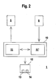
- FIG. 2 shows a block diagram of the device 1 according to FIG. 1.
- the transmitter 5 of the illumination unit 3 and the camera 4 are connected to a two-channel evaluation unit 10 connected, which in the present case of two identical is formed by mutually monitoring computer units 11, 11 '.
- the lighting unit 3 is activated.
- the evaluation of the output signals the receiving elements of the camera 4. It will be used to determine three-dimensional images of the detection area 2 or of in the detection area 2 arranged objects for all receiving elements continuously one distance value each from the light runtime of the illumination unit 3 emitted and reflected back from the detection area 2 Light rays 6 determined.
- an output circuit 12 having a switching output 13 and a warning output 14 connected.
- the evaluation unit 10 is a function of the evaluation of the output signals the receiving elements generates a binary switching signal and via the Switch output 13 issued, by means of which the working fluid can be activated or can be deactivated.
- a switching state of the switching signal is generated, which for deactivation, the means to shut down the working fluid leads.
- the Evaluation unit 10 generates a warning signal when needed, which via the Warning output 14 can be output.
- the distance measurement is performed with the sensor unit after a phase measurement method.
- To carry out the phase measurement is the light beams 6 of the transmitter 5, an amplitude modulation with a predetermined Modulation frequency impressed.
- the phase measurement and thus the detectable distance range can the light beams 6 and a plurality of amplitude modulations with different Modulation frequencies be imprinted.
- the phase measurement is for each receiving element of the CMOS chip 8 the phase difference of the incident there, from the detection area 2 back reflected light beams. 6 with respect to the light beams 6 emitted by the transmitter 5. From these Phase differences are calculated in the evaluation unit 10 respectively distance values. From the totality of the distance values determined for the receiving elements become three-dimensional images of objects in the surveillance area receive.
- the distance measurement is performed with the sensor unit according to a pulse transit time method.
- the transmitter 5 emits Light rays 6 in the form of light pulses.
- the duration of each light pulse from the transmitter 5 to the detection area 2 and back to the camera 4 evaluated. From the Total of all distance values for the individual receiving elements then again three-dimensional images of objects within the detection area 2 received.
- FIG. 3 shows schematically the principle of distance measurement according to a pulse transit time method.
- the first diagram in Figure 3 shows the sequence of the Transmitter 5 emitted light pulses, referred to in Figure 3 as transmitted light pulses.
- the transmitted light pulses each have the same pulse duration T. Also the pulse pauses between two transmitted light pulses are constant.
- the third diagram in Figure 3 shows the emitted by the transmitter 5 and by an object at a distance d to the device 1 back to a receiving element reflected light pulses, referred to in Figure 3 as received light pulses.
- the time duration ⁇ T can be determined by a counting method become. It is with the emission of a transmitted light pulse, preferably with its rising edge, a counter controlled by an oscillator started. With the receipt of the associated received light pulse, preferably with its rising edge, the counter is stopped.
- the time period ⁇ T is determined by means of an integration method.
- the second diagram in FIG. 3 shows sequences of integration intervals during which the output signal generated by the respective received light pulse at the receiving element is integrated.
- the individual integration intervals each extend over the duration of a transmitted light pulse, that is to say the output signal at the receiving element is integrated in each case only during the emission of a transmitted light pulse. Since each received light pulse with respect to the associated transmitted light pulse is delayed by .DELTA.T, only a portion of the received light pulse falls in the corresponding integration interval. Accordingly, for example, for the first received light pulse, the output signal is integrated only during the time interval between t a and t b .
- the integrated output signal U thus obtained is in the fourth diagram of FIG Figure 3 shown.
- Measurement points of the integrated output signal selected. The location of the measuring points is chosen so that they are within a time interval, within which just the received light pulse impinges on the receiving element.
- the evaluation unit 10 has a redundant, two-channel structure two mutually monitoring computer units 11,11 'on.
- the sensor unit in particular the camera 4, has a single-channel structure on. To achieve the required safety level is for the sensor unit a self-fault control performed so that it is self-assured.
- the phase of the light beams 6 impressed amplitude modulation shifted and caused thereby change the distance measurement controlled for the individual receiving elements.
- the evaluation 10 In the object detection by means of the device 1 can in the evaluation 10 generally generates a switching signal for deactivating the working medium when any object in the detection area 2 is registered.
- safety-critical objects and not safety-critical objects are distinguished, with only the intrusion of safety-critical objects in the detection area 2 for deactivation of the working medium leads.
- non-safety-critical objects can be used for example by machine parts, in particular parts of the working medium, workpieces by means of of the working equipment, or also of stationary parts such as Be formed building parts.
- an intervention of such non-safety-critical Objects in the detection area 2 are not endangered, in particular of persons.
- the detection area 2 detected objects with the stored non-safety-critical Objects or, where appropriate, their paths in the Evaluation unit 10 compared. If there is no match of a detected Object detected with a non-safety-critical object, the detected object is classified as a safety-critical object and a Switching signal for decommissioning of the working medium generated.
- the device 1 can be used on stationary and in particular on mobile work equipment for the protection of hazardous areas in the area of this work equipment be arranged.
- the device 1 may be attached to a robot arm be arranged, in which case the robot forms the working means and by movements of the robotic arm hazards to persons arise can.
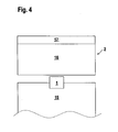
- FIG. 4 shows schematically an arrangement of the device 1 on a working medium forming forklift 15.
- the device 1 at the Front side of the floor conveyor 15 mounted.
- the of the device 1 monitored detection area 2 includes the apron in front of the industrial truck 15.
- the device 1 thus serves to avoid collisions of the Industrial truck 15 with persons and objects. This can be done in the Device 1 in principle then a switching signal for stopping the industrial truck 15, that is, generated to deactivate the work equipment, if an object or a safety-critical object in the detection area 2 is registered.
- the detection area 2 is in a protective field 16 and a non-safety critical area, this area forms a warning zone 17 in the present case.
- this area forms a warning zone 17 in the present case.
- a generation of a switching signal for deactivation of the working medium takes place only if an object or a safety-critical one Object, in or in a protective field 16 within the detection area 2 is registered.
- area does not deactivate the work equipment.
- the non-safety-critical area is a warning zone 17 educated. This means that during an object intervention in the warning zone 17 a warning signal is generated, which is output via the warning output 14 becomes.
- the protective field 16 comprises the immediate vicinity in front of the industrial truck 15, while the non-safety-critical Area to large distances back to the protective field 16 connects. It will the fact that there is a risk for persons, if they are directly in front of the vehicle.
- protective fields can be 16 and not safety-critical Areas as a function of external sensors, so-called muting sensors; respectively.
- protective fields 16 and not safety-critical Areas as hidden zones, so-called blanking areas, depending on the positions of safety-critical objects or not safety-critical objects, in particular depending on predetermined Tracks of such objects, take place.
Landscapes
- Engineering & Computer Science (AREA)
- Physics & Mathematics (AREA)
- General Engineering & Computer Science (AREA)
- Electromagnetism (AREA)
- Mechanical Engineering (AREA)
- Computer Networks & Wireless Communication (AREA)
- General Physics & Mathematics (AREA)
- Radar, Positioning & Navigation (AREA)
- Remote Sensing (AREA)
- Optical Radar Systems And Details Thereof (AREA)
- Machine Tool Sensing Apparatuses (AREA)
- Maintenance And Inspection Apparatuses For Elevators (AREA)
Abstract
Description
- Figur 1:
- Schematische Darstellung der optischen Komponenten einer Vorrichtung zur Erfassung von Objekten.
- Figur 2:
- Blockschaltbild der Vorrichtung gemäß Figur 1.
- Figur 3:
- Zeitdiagramme zur Distanzbestimmung nach dem Puls-Laufzeit-Verfahren für die Vorrichtung gemäß Figur 1.
- Figur 4:
- Anordnung einer Vorrichtung gemäß den Figuren 1 und 2 an einem Flurförderfahrzeug.
- ( 1 )
- Vorrichtung
- (2)
- Erfassungsbereich
- (3)
- Beleuchtungseinheit
- (4)
- Kamera
- (5)
- Sender
- (6)
- Lichtstrahlen
- (7)
- Sendeoptik
- (8)
- CMOS-Chip
- (9)
- Empfangsoptik
- (10)
- Auswerteeinheit
- (11,11')
- Rechnereinheit
- (12)
- Ausgangsschaltung
- (13)
- Schaltausgang
- (14)
- Warnausgang
- (15)
- Flurförderfahrzeug
- (16)
- Schutzfeld
- (17)
- Warnzone
- c
- Lichtgeschwindigkeit
- d
- Distanz des Objekts zur Vorrichtung
- t1, t2, ta, tb
- Zeitpunkte
- T
- Pulsdauer
- U
- Äusgangssignal
- U1, U2
- Messpunkte
- ΔT
- Zeitdauer
Claims (24)
- Vorrichtung (1) zur Überwachung eines Erfassungsbereichs (2) an einem Arbeitsmittel, mit einer Lichtstrahlen (6) emittierenden Beleuchtungseinheit (3) zur Beleuchtung des Erfassungsbereichs (2), mit einer Kamera (4) zur Ermittlung dreidimensionaler Bilder des Erfassungsbereichs (2), wobei die Kamera (4) eine matrixförmige Anordnung von Empfangselementen aufweist, deren Ausgangssignale in einer Auswerteeinheit (10) ausgewertet werden, wobei für jedes Empfangselement ein Distanzwert aus der Lichtlaufzeit der von der Beleuchtungseinheit (3) emittierten und aus dem Erfassungsbereich (2) zurückreflektierten Lichtstrahlen (6) ermittelt wird, und wobei mit der Auswerteeinheit (10) wenigstens ein auf das Arbeitsmittel geführter Schaltausgang (13) angesteuert wird, so dass das Arbeitsmittel nur dann in Betrieb gesetzt ist, falls sich kein Objekt im Erfassungsbereich (2) befindet.
- Vorrichtung nach Anspruch 1, dadurch gekennzeichnet, dass die Kamera (4) einen CCD-Chip oder CMOS-Chip (8) mit einer rechteckigen oder quadratischen Anordnung von Empfangselementen aufweist.
- Vorrichtung nach einem der Ansprüche 1 oder 2, dadurch gekennzeichnet, dass die Beleuchtungseinheit (3) wenigstens einen Lichtstrahlen (6) emittierenden Sender (5) und eine diesem nachgeordnete Sendeoptik (7) aufweist.
- Vorrichtung nach Anspruch 3, dadurch gekennzeichnet, dass der Sender (5) der Beleuchtungseinheit (3) von einer Leuchtdiode oder einer Laserdiode gebildet ist.
- Vorrichtung nach einem der Ansprüche 1-4, dadurch gekennzeichnet, dass die Ermittlung von Distanzwerten nach einem Puls-Laufzeit-Verfahren erfolgt.
- Vorrichtung nach Anspruch 5, dadurch gekennzeichnet, dass der Sender (5) Lichtstrahlen (6) in Form von Lichtimpulsen emittiert.
- Vorrichtung nach einem der Ansprüche 1-4, dadurch gekennzeichnet, dass die Ermittlung von Distanzwerten nach einem Phasenmessverfahren erfolgt.
- Vorrichtung nach Anspruch 7, dadurch gekennzeichnet, dass den vom Sender (5) emittierten Lichtstrahlen (6) eine Amplitudenmodulation mit wenigstens einer vorgegebenen Modulationsfrequenz aufgeprägt ist.
- Vorrichtung nach einem der Ansprüche 1 - 8, dadurch gekennzeichnet, dass in der Auswerteeinheit (10) eine Unterscheidung von sicherheitskritischen. Objekten und nicht sicherheitskritischen Objekten erfolgt, und dass über die Auswerteeinheit (10) das Arbeitsmittel nur dann in Betrieb gesetzt wird, falls sich kein sicherheitskritisches Objekt im Erfassungsbereich (2) befindet.
- Vorrichtung nach Anspruch 9, dadurch gekennzeichnet, dass in einem Einlernvorgang nicht sicherheitskritische Objekte eingelernt und in der Auswerteeinheit (10) abgespeichert werden.
- Vorrichtung nach Anspruch 10, dadurch gekennzeichnet, dass während des Einlernvorgangs Konturen von nicht sicherheitskritischen Objekten eingelernt werden.
- Vorrichtung nach einem der Ansprüche 10 oder 11, dadurch gekennzeichnet, dass während des Einlernvorganges Bahnbewegungen von nicht sicherheitskritischen Objekten eingelernt werden.
- Vorrichtung nach einem der Ansprüche 1-12, dadurch gekennzeichnet, dass der Erfassungsbereich (2) in wenigstens eine Schutzzone und in wenigstens einen nicht sicherheitskritischen Bereich unterteilbar ist, wobei nur Objekterfassungen in dem nicht sicherheitskritischen Bereich nicht zu einem Außerbetriebsetzen des Arbeitsmittels führen.
- Vorrichtung nach Anspruch 13, dadurch gekennzeichnet, dass wenigstens ein Teil eines nicht sicherheitskritischen Bereichs eine Warnzone (17) bildet, wobei bei einer Objekterfassung in der Warnzone (17) über die Auswerteeinheit (10) ein Warnsignal generiert wird.
- Vorrichtung nach einem der Ansprüche 13 oder 14, dadurch gekennzeichnet, dass die nicht sicherheitskritischen Bereiche in Abhängigkeit der Positionen von sicherheitskritischen Objekten oder nicht sicherheitskritischen Objekten innerhalb des Erfassungsbereichs (2) definiert sind.
- Vorrichtung nach einem der Ansprüche 13 oder 14, dadurch gekennzeichnet, dass die nicht sicherheitskritischen. Bereiche in Abhängigkeit von Signalen externer Sensoren definiert sind.
- Vorrichtung nach einem der Ansprüche 1-16, dadurch gekennzeichnet, dass die von der Beleuchtungseinheit (3) und der Kamera (4) gebildete Sensoreinheit einen einkanaligen Aufbau aufweist.
- Vorrichtung nach Anspruch 17, dadurch gekennzeichnet, dass die Sensoreinheit durch eine Eigenfehlerkontrolle selbstsicher ist.
- Vorrichtung nach Anspruch 18, dadurch gekennzeichnet, dass bei einer nach einem Puls-Laufzeit-Verfahren arbeitenden Sensoreinheit zur Eigenfehlerkontrolle die vom Sender (5) emittierten Lichtimpulse um vorgegebene Zeiten verzögert werden und die dadurch veränderten Distanzwerte der Empfangselemente ausgewertet werden.
- Vorrichtung nach Anspruch 18, dadurch gekennzeichnet, dass bei einer nach dem Phasenmessverfahren arbeitenden Sensoreinheit zur Eigenfehlerkontrolle die Phase der den Lichtstrahlen (6) aufgeprägten Amplitudenmodulation verschoben wird und die dadurch veränderten Distanzwerte der Empfangselemente ausgewertet werden.
- Vorrichtung nach einem der Ansprüche 1 - 20, dadurch gekennzeichnet, dass die Auswerteeinheit (10) einen zweikanaligen Aufbau aufweist.
- Vorrichtung nach Anspruch 21, dadurch gekennzeichnet, dass die Auswerteeinheit (10) zwei sich gegenseitig kontrollierende Rechnereinheiten (11, 11') aufweist.
- Vorrichtung nach einem der Ansprüche 1 - 22, dadurch gekennzeichnet, dass mit dieser ein Erfassungsbereich (2) vor einem mobilen Arbeitsmittel überwacht wird.
- Vorrichtung nach Anspruch 23, dadurch gekennzeichnet, dass das mobile Arbeitsmittel von einem Roboter oder einem Transportfahrzeug gebildet ist.
Applications Claiming Priority (2)
| Application Number | Priority Date | Filing Date | Title |
|---|---|---|---|
| DE10360174A DE10360174B4 (de) | 2003-12-20 | 2003-12-20 | Vorrichtung zur Überwachung eines Erfassungsbereichs an einem Arbeitsmittel |
| DE10360174 | 2003-12-20 |
Publications (2)
| Publication Number | Publication Date |
|---|---|
| EP1544535A1 true EP1544535A1 (de) | 2005-06-22 |
| EP1544535B1 EP1544535B1 (de) | 2008-07-30 |
Family
ID=34485552
Family Applications (1)
| Application Number | Title | Priority Date | Filing Date |
|---|---|---|---|
| EP04029035A Expired - Lifetime EP1544535B1 (de) | 2003-12-20 | 2004-12-08 | Vorrichtung zur Überwachung eines Erfassungsbereichs an einem Arbeitsmittel |
Country Status (4)
| Country | Link |
|---|---|
| US (1) | US8698893B2 (de) |
| EP (1) | EP1544535B1 (de) |
| AT (1) | ATE403107T1 (de) |
| DE (2) | DE10360174B4 (de) |
Cited By (8)
| Publication number | Priority date | Publication date | Assignee | Title |
|---|---|---|---|---|
| WO2007054359A3 (de) * | 2005-11-14 | 2007-11-22 | Pilz Gmbh & Co Kg | Vorrichtung und verfahren zum überwachen eines raumbereichs, insbesondere zum absichern eines gefahrenbereichs einer automatisiert arbeitenden anlage |
| EP1837586A3 (de) * | 2006-03-21 | 2008-06-25 | Leuze lumiflex GmbH + Co. KG | Vorrichtung zur Überwachung eines Gefahrenbereichs an einem Arbeitsmittel |
| WO2008107067A1 (de) * | 2007-03-06 | 2008-09-12 | Cedes Ag | Sensorvorrichtung sowie anlage mit einem förderer und einer sensorvorrichtung |
| EP2048557A1 (de) * | 2007-10-11 | 2009-04-15 | Sick Ag | Optoelektronischer Sensor und mobile Vorrichtung sowie Verfahren zur Konfiguration |
| CN101850846A (zh) * | 2010-05-06 | 2010-10-06 | 中国科学院武汉物理与数学研究所 | 激光智能主动规避飞行物装置及其规避飞行物的方法 |
| DE102016014851A1 (de) * | 2016-12-14 | 2018-06-14 | Alexander Zielbach | Umrisspulsmodulationsmessung |
| US10404698B1 (en) | 2016-01-15 | 2019-09-03 | F5 Networks, Inc. | Methods for adaptive organization of web application access points in webtops and devices thereof |
| US10834065B1 (en) | 2015-03-31 | 2020-11-10 | F5 Networks, Inc. | Methods for SSL protected NTLM re-authentication and devices thereof |
Families Citing this family (36)
| Publication number | Priority date | Publication date | Assignee | Title |
|---|---|---|---|---|
| US8954251B2 (en) | 2004-10-05 | 2015-02-10 | Vision Works Ip Corporation | Absolute acceleration sensor for use within moving vehicles |
| US8903617B2 (en) | 2004-10-05 | 2014-12-02 | Vision Works Ip Corporation | Absolute acceleration sensor for use within moving vehicles |
| US7239953B2 (en) | 2004-10-05 | 2007-07-03 | Vision Works, Llc | Absolute acceleration sensor for use within moving vehicles |
| US9878693B2 (en) | 2004-10-05 | 2018-01-30 | Vision Works Ip Corporation | Absolute acceleration sensor for use within moving vehicles |
| US9327726B2 (en) | 2004-10-05 | 2016-05-03 | Vision Works Ip Corporation | Absolute acceleration sensor for use within moving vehicles |
| US8437935B2 (en) | 2004-10-05 | 2013-05-07 | Vision Works Ip Corporation | Absolute acceleration sensor for use within moving vehicles |
| FR2894318B1 (fr) * | 2005-12-07 | 2008-03-07 | Lectra Sa | Procede de gestion de securite active pour une machine de travail automatique. |
| US20070150094A1 (en) * | 2005-12-23 | 2007-06-28 | Qingfeng Huang | System and method for planning and indirectly guiding robotic actions based on external factor tracking and analysis |
| DE102006008805B4 (de) * | 2006-02-25 | 2014-07-24 | Leuze Lumiflex Gmbh + Co. Kg | Optischer Sensor und Verfahren zur Überwachung einer Schutzzone mittels eines optischen Sensors |
| DE102006041756A1 (de) * | 2006-09-04 | 2008-03-06 | Robert Bosch Gmbh | Werkzeugmaschinenüberwachungsvorrichtung |
| DE102007008806C5 (de) | 2006-10-27 | 2010-05-06 | Sick Ag | Optoelektronische Überwachung mit Test durch Dynamisierung |
| DE102006057605A1 (de) * | 2006-11-24 | 2008-06-05 | Pilz Gmbh & Co. Kg | Verfahren und Vorrichtung zum Überwachen eines dreidimensionalen Raumbereichs |
| DE102007009225B3 (de) * | 2007-02-26 | 2008-07-03 | Sick Ag | Bearbeitungsmaschine |
| DE502007001694D1 (de) * | 2007-08-02 | 2009-11-19 | Sick Ag | Dreidimensionale Raumüberwachung mit Konfigurationsmodus zum Bestimmen der Schutzfelder |
| US8250955B2 (en) | 2007-10-22 | 2012-08-28 | Formax, Inc. | Food article transfer mechanism for a food article slicing machine |
| CN101430477B (zh) * | 2007-11-09 | 2011-06-08 | 鸿富锦精密工业(深圳)有限公司 | 判断被摄物体距离的方法 |
| DE102008011946A1 (de) * | 2008-02-29 | 2009-09-10 | Robert Bosch Gmbh | Geräteschutzvorrichtung |
| DE102009045600B4 (de) | 2009-10-12 | 2021-11-04 | pmdtechnologies ag | Kamerasystem |
| US20120095575A1 (en) * | 2010-10-14 | 2012-04-19 | Cedes Safety & Automation Ag | Time of flight (tof) human machine interface (hmi) |
| US9025019B2 (en) * | 2010-10-18 | 2015-05-05 | Rockwell Automation Technologies, Inc. | Time of flight (TOF) sensors as replacement for standard photoelectric sensors |
| EP2698649B1 (de) † | 2010-11-15 | 2015-07-08 | Cedes AG | Überwachungssensor mit Selbstprüfung |
| DE102012003856A1 (de) * | 2012-02-27 | 2013-08-29 | Andreas Plaas-Link | Anordnung und Verfahren zur Überwachung von Anlagen und Räumen |
| JP6123307B2 (ja) * | 2013-01-23 | 2017-05-10 | 株式会社デンソーウェーブ | ロボット周辺への物体の侵入を監視する監視システムおよび監視方法 |
| US9855986B2 (en) | 2013-08-28 | 2018-01-02 | Vision Works Ip Corporation | Absolute acceleration sensor for use within moving vehicles |
| US9371002B2 (en) | 2013-08-28 | 2016-06-21 | Vision Works Ip Corporation | Absolute acceleration sensor for use within moving vehicles |
| US9834184B2 (en) | 2013-09-13 | 2017-12-05 | Vision Works Ip Corporation | Trailer braking system and controller |
| WO2016022155A1 (en) * | 2014-08-08 | 2016-02-11 | Robotic Vision Technologies, LLC | Sensor-based safety features for robotic equipment |
| DE102015112656A1 (de) * | 2015-07-31 | 2017-02-02 | Sick Ag | Distanzsensor |
| US9868214B2 (en) | 2016-06-20 | 2018-01-16 | X Development Llc | Localization of a mobile system |
| EP3617752B1 (de) * | 2018-08-27 | 2021-07-21 | Syncmold Enterprise Corp. | Detektionssystem und detektionsverfahren |
| EP3671289B1 (de) * | 2018-12-21 | 2021-03-24 | Leuze electronic GmbH + Co. KG | Sensoranordnung |
| CN111176177A (zh) * | 2020-01-04 | 2020-05-19 | 王伟新 | 一种窨井井盖状态监控系统及其工作机制 |
| DE102020114488B3 (de) * | 2020-05-29 | 2021-12-02 | Sick Ag | Optoelektronischer Sicherheitssensor und Verfahren zur Absicherung einer Maschine |
| DE202022103234U1 (de) * | 2022-06-08 | 2023-09-20 | Leuze Electronic Gmbh + Co. Kg | Überwachungseinrichtung |
| DE102023102951B4 (de) * | 2023-02-07 | 2025-03-13 | Sick Ag | Verfahren und berührungsloser Distanzsensor zum Absichern einer Maschine |
| DE202024103699U1 (de) * | 2024-07-04 | 2025-10-08 | Leuze Electronic Gmbh + Co. Kg | Sensoranordnung |
Citations (5)
| Publication number | Priority date | Publication date | Assignee | Title |
|---|---|---|---|---|
| DE4414434A1 (de) * | 1994-04-26 | 1995-11-02 | Ruhrkohle Ag | Personenerkennung bei der Bandfahrung |
| DE19619186C1 (de) * | 1996-05-02 | 1998-01-02 | Pco Computer Optics Gmbh | Verfahren sowie System zur Erstellung eines Bildes |
| US6373557B1 (en) * | 1997-12-23 | 2002-04-16 | Siemens Aktiengesellschaft | Method and apparatus for picking up a three-dimensional range image |
| US20030123707A1 (en) * | 2001-12-31 | 2003-07-03 | Park Seujeung P. | Imaging-based distance measurement and three-dimensional profiling system |
| EP1367314A2 (de) * | 2002-05-31 | 2003-12-03 | Leuze lumiflex GmbH + Co. KG | Vorrichtung zur Überwachung eines Erfassungsbereiches an einem Arbeitsmittel |
Family Cites Families (17)
| Publication number | Priority date | Publication date | Assignee | Title |
|---|---|---|---|---|
| US5283641A (en) * | 1954-12-24 | 1994-02-01 | Lemelson Jerome H | Apparatus and methods for automated analysis |
| US4422961A (en) | 1982-03-01 | 1983-12-27 | Olin Corporation | Raney alloy methanation catalyst |
| US5694203A (en) * | 1995-01-31 | 1997-12-02 | Kabushikikaisha Wacom | Distance camera device having light gate for extracting distance information |
| DE19511990C2 (de) * | 1995-03-31 | 1997-09-11 | Koch Alexander W Prof Dr Ing H | Messvorrichtung zum Messen von Transversalgeschwindigkeit und Länge eines Messobjekts |
| DE19544632A1 (de) * | 1995-11-30 | 1997-06-05 | Leuze Electronic Gmbh & Co | Optoelektronische Vorrichtung zum Erfassen von Objekten in einem Überwachungsbereich |
| DE19645175A1 (de) * | 1996-11-02 | 1998-05-07 | Telefunken Microelectron | Verfahren zum Steuern einer optischen Überwachungseinrichtung |
| DE59811662D1 (de) * | 1997-04-30 | 2004-08-19 | Sick Ag | Opto-elektronische Sensoranordnung mit mehreren in einer Zeile oder einem Array angeordneten photoempfindlichen Elementen |
| DE19833207A1 (de) * | 1998-07-23 | 2000-02-17 | Siemens Ag | Verfahren und Vorrichtung zur Aufnahme eines dreidimensionalen Abstandsbildes |
| DE19821974B4 (de) * | 1998-05-18 | 2008-04-10 | Schwarte, Rudolf, Prof. Dr.-Ing. | Vorrichtung und Verfahren zur Erfassung von Phase und Amplitude elektromagnetischer Wellen |
| DE10000287B4 (de) * | 2000-01-07 | 2004-02-12 | Leuze Lumiflex Gmbh + Co. Kg | Vorrichtung und Verfahren zur Überwachung eines Erfassungsbereichs an einem Arbeitsmittel |
| EP1148353A3 (de) * | 2000-04-22 | 2003-05-28 | Leuze electronic GmbH + Co. | Optischer Sensor |
| EP1148352B1 (de) * | 2000-04-22 | 2010-10-06 | Leuze electronic GmbH + Co. KG | Optischer Sensor |
| DE10026306A1 (de) | 2000-05-26 | 2001-11-29 | Tutogen Medical Gmbh | Transplantat |
| DE10026305A1 (de) * | 2000-05-26 | 2001-11-29 | Sick Ag | Optoelektronische Vorrichtung |
| DE10026710A1 (de) * | 2000-05-30 | 2001-12-06 | Sick Ag | Optoelektronische Schutzeinrichtung |
| DE10163534A1 (de) * | 2001-12-21 | 2003-07-10 | Siemens Ag | Vorrichtung zur Überwachung von Raumbereichen |
| US7315383B1 (en) * | 2004-07-09 | 2008-01-01 | Mohsen Abdollahi | Scanning 3D measurement technique using structured lighting and high-speed CMOS imager |
-
2003
- 2003-12-20 DE DE10360174A patent/DE10360174B4/de not_active Revoked
-
2004
- 2004-12-08 DE DE502004007728T patent/DE502004007728D1/de not_active Expired - Lifetime
- 2004-12-08 AT AT04029035T patent/ATE403107T1/de active
- 2004-12-08 EP EP04029035A patent/EP1544535B1/de not_active Expired - Lifetime
-
2005
- 2005-05-04 US US11/121,103 patent/US8698893B2/en active Active
Patent Citations (5)
| Publication number | Priority date | Publication date | Assignee | Title |
|---|---|---|---|---|
| DE4414434A1 (de) * | 1994-04-26 | 1995-11-02 | Ruhrkohle Ag | Personenerkennung bei der Bandfahrung |
| DE19619186C1 (de) * | 1996-05-02 | 1998-01-02 | Pco Computer Optics Gmbh | Verfahren sowie System zur Erstellung eines Bildes |
| US6373557B1 (en) * | 1997-12-23 | 2002-04-16 | Siemens Aktiengesellschaft | Method and apparatus for picking up a three-dimensional range image |
| US20030123707A1 (en) * | 2001-12-31 | 2003-07-03 | Park Seujeung P. | Imaging-based distance measurement and three-dimensional profiling system |
| EP1367314A2 (de) * | 2002-05-31 | 2003-12-03 | Leuze lumiflex GmbH + Co. KG | Vorrichtung zur Überwachung eines Erfassungsbereiches an einem Arbeitsmittel |
Cited By (11)
| Publication number | Priority date | Publication date | Assignee | Title |
|---|---|---|---|---|
| WO2007054359A3 (de) * | 2005-11-14 | 2007-11-22 | Pilz Gmbh & Co Kg | Vorrichtung und verfahren zum überwachen eines raumbereichs, insbesondere zum absichern eines gefahrenbereichs einer automatisiert arbeitenden anlage |
| US8224032B2 (en) | 2005-11-14 | 2012-07-17 | Pilz Gmbh & Co. Kg | Apparatus and method for monitoring a spatial area, in particular for safeguarding a hazardous area of an automatically operated installation |
| EP1837586A3 (de) * | 2006-03-21 | 2008-06-25 | Leuze lumiflex GmbH + Co. KG | Vorrichtung zur Überwachung eines Gefahrenbereichs an einem Arbeitsmittel |
| WO2008107067A1 (de) * | 2007-03-06 | 2008-09-12 | Cedes Ag | Sensorvorrichtung sowie anlage mit einem förderer und einer sensorvorrichtung |
| US8107058B2 (en) | 2007-03-06 | 2012-01-31 | Cedes Ag | Sensor device and system having a conveyor and a sensor device |
| EP2048557A1 (de) * | 2007-10-11 | 2009-04-15 | Sick Ag | Optoelektronischer Sensor und mobile Vorrichtung sowie Verfahren zur Konfiguration |
| CN101850846A (zh) * | 2010-05-06 | 2010-10-06 | 中国科学院武汉物理与数学研究所 | 激光智能主动规避飞行物装置及其规避飞行物的方法 |
| CN101850846B (zh) * | 2010-05-06 | 2012-11-14 | 中国科学院武汉物理与数学研究所 | 激光智能主动规避飞行物装置及其规避飞行物的方法 |
| US10834065B1 (en) | 2015-03-31 | 2020-11-10 | F5 Networks, Inc. | Methods for SSL protected NTLM re-authentication and devices thereof |
| US10404698B1 (en) | 2016-01-15 | 2019-09-03 | F5 Networks, Inc. | Methods for adaptive organization of web application access points in webtops and devices thereof |
| DE102016014851A1 (de) * | 2016-12-14 | 2018-06-14 | Alexander Zielbach | Umrisspulsmodulationsmessung |
Also Published As
| Publication number | Publication date |
|---|---|
| EP1544535B1 (de) | 2008-07-30 |
| DE10360174B4 (de) | 2007-03-08 |
| ATE403107T1 (de) | 2008-08-15 |
| DE10360174A1 (de) | 2005-07-21 |
| US8698893B2 (en) | 2014-04-15 |
| DE502004007728D1 (de) | 2008-09-11 |
| US20050207619A1 (en) | 2005-09-22 |
Similar Documents
| Publication | Publication Date | Title |
|---|---|---|
| EP1544535B1 (de) | Vorrichtung zur Überwachung eines Erfassungsbereichs an einem Arbeitsmittel | |
| DE10360789B4 (de) | Vorrichtung zur Überwachung eines Erfassungsbereichs an einem Arbeitsmittel | |
| EP1927867B1 (de) | Optoelektronischer Mehrebenensensor und Verfahren zur Erfassung von Objekten | |
| EP3260885B1 (de) | Optoelektronischer sensor und verfahren zur erfassung von objekten | |
| EP2541273B1 (de) | Erfassung und Abstandsbestimmung von Objekten | |
| DE19917509C1 (de) | Optoelektronische Vorrichtung | |
| EP1788467B1 (de) | Schutzeinrichtung | |
| EP3435117A1 (de) | Sensor und verfahren zur erfassung und abstandsbestimmung von objekten | |
| EP3217195B1 (de) | Optischer sensor | |
| EP3220164B1 (de) | Verfahren zum betreiben eines abstandsmessenden überwachungssensors und überwachungssensor | |
| EP3287809A1 (de) | Verfahren zum betreiben eines scanners und scanner | |
| EP1826589B1 (de) | Optischer Sensor zur Überwachung einer Schutzzone | |
| EP1837586B1 (de) | Vorrichtung zur Überwachung eines Gefahrenbereichs an einem Arbeitsmittel | |
| EP3825731B1 (de) | Optoelektronischer sicherheitssensor und verfahren zur sicheren bestimmung der eigenen position | |
| DE102017119283B4 (de) | Sensorsystem | |
| EP3640522B1 (de) | Überwachungsvorrichtung | |
| DE102006008805B4 (de) | Optischer Sensor und Verfahren zur Überwachung einer Schutzzone mittels eines optischen Sensors | |
| EP3527332A1 (de) | Sichere sensorvorrichtung und verfahren zur absicherung einer beweglichen maschine | |
| EP3974699A1 (de) | Überwachungseinrichtung | |
| DE102017103791B4 (de) | Optoelektronischer Sensor und Verfahren zur Erfassung von Objekten | |
| DE102023115311B4 (de) | Zugangsabsicherungssystem | |
| DE29716601U1 (de) | Überwachungseinrichtung zur Detektion von bewegten Objekten | |
| DE102017004030B4 (de) | Verfahren und Vorrichtung zum Sichern eines Arbeitsraums | |
| EP3872526B1 (de) | Vorrichtung zum überwachen eines schutzbereichs | |
| EP3629066B1 (de) | Optischer sensor |
Legal Events
| Date | Code | Title | Description |
|---|---|---|---|
| PUAI | Public reference made under article 153(3) epc to a published international application that has entered the european phase |
Free format text: ORIGINAL CODE: 0009012 |
|
| AK | Designated contracting states |
Kind code of ref document: A1 Designated state(s): AT BE BG CH CY CZ DE DK EE ES FI FR GB GR HU IE IS IT LI LT LU MC NL PL PT RO SE SI SK TR |
|
| AX | Request for extension of the european patent |
Extension state: AL BA HR LV MK YU |
|
| 17P | Request for examination filed |
Effective date: 20050623 |
|
| AKX | Designation fees paid |
Designated state(s): AT BE BG CH CY CZ DE DK EE ES FI FR GB GR HU IE IS IT LI LT LU MC NL PL PT RO SE SI SK TR |
|
| 17Q | First examination report despatched |
Effective date: 20070402 |
|
| GRAP | Despatch of communication of intention to grant a patent |
Free format text: ORIGINAL CODE: EPIDOSNIGR1 |
|
| GRAS | Grant fee paid |
Free format text: ORIGINAL CODE: EPIDOSNIGR3 |
|
| GRAA | (expected) grant |
Free format text: ORIGINAL CODE: 0009210 |
|
| RBV | Designated contracting states (corrected) |
Designated state(s): AT CH DE FR GB LI |
|
| AK | Designated contracting states |
Kind code of ref document: B1 Designated state(s): AT CH DE FR GB LI |
|
| REG | Reference to a national code |
Ref country code: GB Ref legal event code: FG4D Free format text: NOT ENGLISH |
|
| REG | Reference to a national code |
Ref country code: CH Ref legal event code: NV Representative=s name: ROTTMANN, ZIMMERMANN + PARTNER AG Ref country code: CH Ref legal event code: EP |
|
| REF | Corresponds to: |
Ref document number: 502004007728 Country of ref document: DE Date of ref document: 20080911 Kind code of ref document: P |
|
| PLBE | No opposition filed within time limit |
Free format text: ORIGINAL CODE: 0009261 |
|
| STAA | Information on the status of an ep patent application or granted ep patent |
Free format text: STATUS: NO OPPOSITION FILED WITHIN TIME LIMIT |
|
| 26N | No opposition filed |
Effective date: 20090506 |
|
| REG | Reference to a national code |
Ref country code: CH Ref legal event code: PFA Owner name: LEUZE LUMIFLEX GMBH + CO. KG Free format text: LEUZE LUMIFLEX GMBH + CO. KG#LIEBIGSTRASSE 4#82256 FUERSTENFELDBRUCK (DE) -TRANSFER TO- LEUZE LUMIFLEX GMBH + CO. KG#LIEBIGSTRASSE 4#82256 FUERSTENFELDBRUCK (DE) |
|
| PGFP | Annual fee paid to national office [announced via postgrant information from national office to epo] |
Ref country code: AT Payment date: 20131211 Year of fee payment: 10 |
|
| REG | Reference to a national code |
Ref country code: AT Ref legal event code: MM01 Ref document number: 403107 Country of ref document: AT Kind code of ref document: T Effective date: 20141208 |
|
| PG25 | Lapsed in a contracting state [announced via postgrant information from national office to epo] |
Ref country code: AT Free format text: LAPSE BECAUSE OF NON-PAYMENT OF DUE FEES Effective date: 20141208 |
|
| REG | Reference to a national code |
Ref country code: FR Ref legal event code: PLFP Year of fee payment: 12 |
|
| PGFP | Annual fee paid to national office [announced via postgrant information from national office to epo] |
Ref country code: GB Payment date: 20151221 Year of fee payment: 12 |
|
| REG | Reference to a national code |
Ref country code: CH Ref legal event code: PCAR Free format text: NEW ADDRESS: GARTENSTRASSE 28 A, 5400 BADEN (CH) |
|
| REG | Reference to a national code |
Ref country code: FR Ref legal event code: PLFP Year of fee payment: 13 |
|
| GBPC | Gb: european patent ceased through non-payment of renewal fee |
Effective date: 20161208 |
|
| PG25 | Lapsed in a contracting state [announced via postgrant information from national office to epo] |
Ref country code: GB Free format text: LAPSE BECAUSE OF NON-PAYMENT OF DUE FEES Effective date: 20161208 |
|
| REG | Reference to a national code |
Ref country code: FR Ref legal event code: PLFP Year of fee payment: 14 |
|
| PGFP | Annual fee paid to national office [announced via postgrant information from national office to epo] |
Ref country code: FR Payment date: 20171221 Year of fee payment: 14 |
|
| PGFP | Annual fee paid to national office [announced via postgrant information from national office to epo] |
Ref country code: CH Payment date: 20171220 Year of fee payment: 14 |
|
| REG | Reference to a national code |
Ref country code: CH Ref legal event code: PL |
|
| PG25 | Lapsed in a contracting state [announced via postgrant information from national office to epo] |
Ref country code: FR Free format text: LAPSE BECAUSE OF NON-PAYMENT OF DUE FEES Effective date: 20181231 |
|
| PG25 | Lapsed in a contracting state [announced via postgrant information from national office to epo] |
Ref country code: LI Free format text: LAPSE BECAUSE OF NON-PAYMENT OF DUE FEES Effective date: 20181231 Ref country code: CH Free format text: LAPSE BECAUSE OF NON-PAYMENT OF DUE FEES Effective date: 20181231 |
|
| REG | Reference to a national code |
Ref country code: DE Ref legal event code: R082 Ref document number: 502004007728 Country of ref document: DE Representative=s name: RUCKH, RAINER, DIPL.-PHYS. DR.RER.NAT., DE Ref country code: DE Ref legal event code: R081 Ref document number: 502004007728 Country of ref document: DE Owner name: ROCKWELL AUTOMATION TECHNOLOGIES, INC., MAYFIE, US Free format text: FORMER OWNER: LEUZE LUMIFLEX GMBH + CO. KG, 82256 FUERSTENFELDBRUCK, DE |
|
| REG | Reference to a national code |
Ref country code: DE Ref legal event code: R081 Ref document number: 502004007728 Country of ref document: DE Owner name: ROCKWELL AUTOMATION TECHNOLOGIES, INC., MAYFIE, US Free format text: FORMER OWNER: LEUZE ELECTRONIC GMBH + CO. KG, 73277 OWEN, DE Ref country code: DE Ref legal event code: R082 Ref document number: 502004007728 Country of ref document: DE Representative=s name: GRUENECKER PATENT- UND RECHTSANWAELTE PARTG MB, DE |
|
| P01 | Opt-out of the competence of the unified patent court (upc) registered |
Effective date: 20230404 |
|
| PGFP | Annual fee paid to national office [announced via postgrant information from national office to epo] |
Ref country code: DE Payment date: 20231121 Year of fee payment: 20 |
|
| REG | Reference to a national code |
Ref country code: DE Ref legal event code: R071 Ref document number: 502004007728 Country of ref document: DE |