EP1544496A2 - Elastic connecting element - Google Patents
Elastic connecting element Download PDFInfo
- Publication number
- EP1544496A2 EP1544496A2 EP04029289A EP04029289A EP1544496A2 EP 1544496 A2 EP1544496 A2 EP 1544496A2 EP 04029289 A EP04029289 A EP 04029289A EP 04029289 A EP04029289 A EP 04029289A EP 1544496 A2 EP1544496 A2 EP 1544496A2
- Authority
- EP
- European Patent Office
- Prior art keywords
- connecting element
- components
- metal wire
- insert
- metallic
- Prior art date
- Legal status (The legal status is an assumption and is not a legal conclusion. Google has not performed a legal analysis and makes no representation as to the accuracy of the status listed.)
- Withdrawn
Links
Images


Classifications
-
- F—MECHANICAL ENGINEERING; LIGHTING; HEATING; WEAPONS; BLASTING
- F16—ENGINEERING ELEMENTS AND UNITS; GENERAL MEASURES FOR PRODUCING AND MAINTAINING EFFECTIVE FUNCTIONING OF MACHINES OR INSTALLATIONS; THERMAL INSULATION IN GENERAL
- F16F—SPRINGS; SHOCK-ABSORBERS; MEANS FOR DAMPING VIBRATION
- F16F1/00—Springs
- F16F1/36—Springs made of rubber or other material having high internal friction, e.g. thermoplastic elastomers
- F16F1/362—Springs made of rubber or other material having high internal friction, e.g. thermoplastic elastomers made of steel wool, compressed hair, woven or non-woven textile, or like materials
-
- F—MECHANICAL ENGINEERING; LIGHTING; HEATING; WEAPONS; BLASTING
- F16—ENGINEERING ELEMENTS AND UNITS; GENERAL MEASURES FOR PRODUCING AND MAINTAINING EFFECTIVE FUNCTIONING OF MACHINES OR INSTALLATIONS; THERMAL INSULATION IN GENERAL
- F16F—SPRINGS; SHOCK-ABSORBERS; MEANS FOR DAMPING VIBRATION
- F16F15/00—Suppression of vibrations in systems; Means or arrangements for avoiding or reducing out-of-balance forces, e.g. due to motion
- F16F15/02—Suppression of vibrations of non-rotating, e.g. reciprocating systems; Suppression of vibrations of rotating systems by use of members not moving with the rotating systems
- F16F15/04—Suppression of vibrations of non-rotating, e.g. reciprocating systems; Suppression of vibrations of rotating systems by use of members not moving with the rotating systems using elastic means
Abstract
Description
Die vorliegende Erfindung betrifft ein elastisches Verbindungselement zum Verbinden von wenigstens zwei Bauteilen nach dem Oberbegriff des Anspruchs 1.The present invention relates to an elastic Connecting element for connecting at least two Components according to the preamble of claim 1.
Im Bereich der Kraftfahrzeugtechnik müssen im allgemeinen verschiedene Motorkomponenten (Bauteile der Erfindung) fest und gleichzeitig elastisch miteinander verbunden werden. Hierbei sollen die Verbindungen eine hohe Festigkeit, insbesondere Schwingfestigkeit und Temperaturfestigkeit sowie gute Körperschallübertragungseigenschaften aufweisen.In the field of automotive engineering in general various engine components (components of the invention) firmly and at the same time be connected to each other elastically. Here, the compounds are high strength, especially fatigue strength and temperature resistance as well have good structure-borne sound transmission properties.
Es ist daher eine Aufgabe der vorliegenden Erfindung, ein elastisches Verbindungselement zum Verbinden von wenigstens zwei Bauteilen vorzusehen, welches gute Elastizitäts-, Festigkeits- sowie Körperschallübertragungseigenschaften aufweist.It is therefore an object of the present invention to provide a elastic connecting element for connecting at least two components to provide, which good elasticity, Strength and structure-borne sound transmission properties having.
Diese Aufgabe wird durch ein elastisches Verbindungselement mit den Merkmalen des Anspruchs 1 gelöst. Vorteilhafte Ausgestaltungen und Weiterbildungen der Erfindung sind Gegenstand der Unteransprüche 2 bis 10.This task is achieved by an elastic connecting element solved with the features of claim 1. advantageous Embodiments and developments of the invention are Subject matter of the subclaims 2 to 10.
Das elastische Verbindungselement zum Verbinden von wenigstens zwei Bauteilen weist jeweils eine Befestigungsvorrichtung zum Befestigen des Verbindungselements mit einem der Bauteile auf und ist aus einem Metalldrahtgestrick aufgebaut, das in ein Formelement gepresst ist, wobei die Befestigungsvorrichtungen derart in das Verbindungselement integriert sind, dass die Richtung der Befestigung des Verbindungselements an die Bauteile im wesentlichen senkrecht zu der Hauptausdehnungsrichtung des Verbindungselements verläuft.The elastic connecting element for connecting at least two components each have one Fastening device for fastening the Connecting element with one of the components and is off a metal wire mesh constructed in a mold element is pressed, wherein the fastening devices in such the fastener are integrated that the direction of the Attachment of the connecting element to the components in substantially perpendicular to the main expansion direction of Connecting element runs.
Das Metalldrahtgestrick gewährleistet aufgrund der seiner Konstruktion inhärenten Coulomb'schen Reibung eine hohe Schwingungsdämpfung (akustisch und schwingungstechnisch) zwischen den wenigstens zwei Bauteilen und verbessert hierdurch das Schwingverhalten der gesamten Baugruppe. Darüber hinaus zeigt das Metalldrahtgestrick eine hohe Temperatur- und Korrosionsfestigkeit, eine ausreichende Elastizität und ein hohes Energieabsorptionsvermögen, sodass es insbesondere auch zur Verbindung von Komponenten eines Kraftfahrzeugmotors gut geeignet ist.The metal wire mesh ensures due to its Construction inherent Coulomb friction a high Vibration damping (acoustic and vibration control) between the at least two components and improved As a result, the vibration behavior of the entire assembly. In addition, the metal wire knit shows a high Temperature and corrosion resistance, adequate Elasticity and high energy absorption capacity, so in particular also for the connection of components of a Motor vehicle engine is well suited.
In einer Ausgestaltung der Erfindung besitzt das Formelement eine balkenartige oder plattenartige Grundform. Diese Grundform kann sowohl geradlinig als auch gekrümmt gewählt sein.In one embodiment of the invention, the shaped element has a bar-like or plate-like basic shape. These Basic shape can be chosen both straight and curved be.
In einer bevorzugten Ausführungsform ist das Metalldrahtgestrick einseitig oder beidseitig mit einer Deckschicht aus einem metallischen oder nicht-metallischen Material versehen. Mittels dieser Deckschichten kann das Schwing- und Übertragungsverhalten über weite Frequenzbereiche gezielt beeinflusst werden. Im Fall der Verwendung eines Elastomers für die Deckschichten wird das Dämpfungsverhalten durch Scherung erzeugt. In a preferred embodiment this is Metal wire knit on one side or both sides with one Cover layer of a metallic or non-metallic Material provided. By means of these cover layers, the Oscillation and transmission behavior over a long distance Frequency ranges are influenced in a targeted manner. In the case of Use of an elastomer for the outer layers becomes the Damping behavior generated by shear.
In einer alternativen Ausführungsform sind zwei Metalldrahtgestricke vorgesehen, zwischen denen eine Einlage vorgesehen ist, oder das Metalldrahtgestrick ist mit einer Füllung versehen, wobei die Einlage bzw. die Füllung aus einem metallischen oder nicht-metallischen Material, vorzugsweise einem elastomeren Material besteht. Auch in diesem Fall kann das Schwing- und Übertragungsverhalten des Verbindungselements über beide Frequenzbereiche gezielt beeinflusst werden.In an alternative embodiment, two Metal wire knit provided between which an insert is provided, or the metal wire mesh is with a Fill provided, with the insert or the filling a metallic or non-metallic material, preferably an elastomeric material. Also in In this case, the vibration and transmission behavior of the Connecting element targeted over both frequency ranges to be influenced.
In einer weiteren alternativen Ausführungsform der Erfindung ist das Metalldrahtgestrick einseitig oder beidseitig mit einer tragenden Montageplatte verbunden. Diese Montageplatten erhöhen die Festigkeit bzw. Stabilität der Verbindung.In a further alternative embodiment of the invention the metal wire mesh is single-sided or double-sided connected to a supporting mounting plate. These mounting plates increase the strength and stability of the connection.
Die Befestigungsvorrichtungen des elastischen Verbindungselements können Buchsen, Hülsen oder Durchbohrungen sein, durch welche ein Befestigungselement, wie beispielsweise eine Schraube oder eine Niete, zum Eingriff mit dem Bauteil hindurch geführt werden kann.The fastening devices of the elastic Connecting element can jacks, sleeves or Be through holes through which a fastener, such as a screw or a rivet, for Intervention can be performed with the component.
Das Verbindungselement der Erfindung ist besonders bevorzugt bei einer Anordnung aus wenigstens zwei miteinander verbundenen Bauteilen einsetzbar, welche Bauteile eines Motorsystems eines Kraftfahrzeugs sind.The connecting element of the invention is particularly preferred in an arrangement of at least two together connected components used, which components of a Motor system of a motor vehicle.
Je nach Form des zu verbindenden Bauteils kann ferner zwischen dem Bauteil und dem Verbindungselement ein Kupplungselement zum formschlüssigen Anschluss von Bauteil und Verbindungselement vorgesehen sein.Depending on the shape of the component to be connected may also between the component and the connecting element Coupling element for the positive connection of component and connecting element may be provided.
Weitere Merkmale und Merkmalskombinationen ergeben sich aus der Beschreibung sowie den Zeichnungen. Konkrete Ausführungsbeispiele der Erfindung sind in den Zeichnungen vereinfacht dargestellt und in der nachfolgenden Beschreibung näher erläutert. Dabei zeigen:
- Fig. 1
- eine schematische Darstellung eines Ausschnitts einer Baugruppe, bei welcher zwei Bauteile mit einem elastischen Verbindungselement gemäß der vorliegenden Erfindung verbunden sind;
- Fig. 2
- eine schematische Darstellung eines Ausschnitts einer weiteren Baugruppe, bei welcher die Bauteile mit einem elastischen Verbindungselement gemäß der vorliegenden Erfindung verbunden sind;
- Fig. 3
- eine schematische Darstellung eines Ausschnitts einer noch weiteren Baugruppe, bei welcher die beiden Bauteile mittels eines Verbindungselements gemäß der vorliegenden Erfindung miteinander verbunden sind;
- Fig. 4
- eine Querschnittsdarstellung und eine Draufsicht eines elastischen Verbindungselements gemäß einem ersten Ausführungsbeispiel der vorliegenden Erfindung;
- Fig. 5
- eine Querschnittsdarstellung und eine Draufsicht eines Verbindungselements gemäß einem zweiten Ausführungsbeispiel der vorliegenden Erfindung;
- Fig. 6
- eine Querschnittsdarstellung und eine Draufsicht eines Verbindungselements gemäß einem dritten Ausführungsbeispiel der vorliegenden Erfindung;
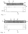
- Fig. 7
- eine Querschnittsdarstellung und eine Draufsicht eines Verbindungselements gemäß einem vierten Ausführungsbeispiel der vorliegenden Erfindung; und
- Fig. 8
- eine Querschnittsdarstellung und eine Draufsicht eines Verbindungselements gemäß einem fünften Ausführungsbeispiel der vorliegenden Erfindung.
- Fig. 1
- a schematic representation of a section of an assembly in which two components are connected to an elastic connecting element according to the present invention;
- Fig. 2
- a schematic representation of a section of another assembly in which the components are connected to an elastic connecting element according to the present invention;
- Fig. 3
- a schematic representation of a section of a still further assembly in which the two components are interconnected by means of a connecting element according to the present invention;
- Fig. 4
- a cross-sectional view and a plan view of an elastic connecting element according to a first embodiment of the present invention;
- Fig. 5
- a cross-sectional view and a plan view of a connecting element according to a second embodiment of the present invention;
- Fig. 6
- a cross-sectional view and a plan view of a connecting element according to a third embodiment of the present invention;
- Fig. 7
- a cross-sectional view and a plan view of a connecting element according to a fourth embodiment of the present invention; and
- Fig. 8
- a cross-sectional view and a plan view of a connecting element according to a fifth embodiment of the present invention.
In den Darstellungen der Fig. 1 bis 3 sind ausschnittweise verschiedene Baugruppen eines Motorsystems eines Kraftfahrzeugs dargestellt, bei welchen die Bauteile jeweils durch ein elastisches Verbindungselement gemäß der vorliegenden Erfindung miteinander verbunden sind. Anhand der Fig. 4 bis 8 werden verschiedene Ausführungsbeispiele eines elastischen Verbindungselements gemäß der vorliegenden Erfindung erläutert, die beispielsweise in den Baugruppen der Fig. 1 bis 3 einsetzbar sind.In the illustrations of Figs. 1 to 3 are fragmentary various assemblies of an engine system one Motor vehicle shown, in which the components each by an elastic connecting element according to the present invention are interconnected. Based on Figs. 4 to 8 will be various embodiments of a elastic connecting element according to the present invention Invention explained, for example, in the modules of Fig. 1 to 3 are used.
Fig. 1 zeigt beispielhaft eine Verbindung zwischen einem
ersten Bauteil 10, zum Beispiel einem Motorblock, und einem
zweiten Bauteil 12, zum Beispiel einer Konsole, eines
Motorsystems eines Kraftfahrzeugs. Die beiden Bauteile 10 und
12 sind mittels eines elastischen Verbindungselements 14
miteinander verbunden. Das elastische Verbindungselement 14
weist an seinen beiden Endabschnitten jeweils eine
Befestigungsvorrichtung 18 in Form einer Buchse auf, durch
welche jeweils ein Befestigungselement, wie beispielsweise
eine Schraube, ein Bolzen oder eine Niete hindurch geführt
werden kann. Mit der Befestigungsvorrichtung 18 und einem
entsprechenden Befestigungselement (nicht dargestellt) wird
das Verbindungselement 14 derart an den beiden Bauteilen 10
und 12 befestigt, dass die Richtung der Befestigung des
Verbindungselements an die Bauteile (Oben/Unten-Richtung in
Fig. 1) im wesentlichen senkrecht zu der
Hauptausdehnungsrichtung des Verbindungselements
(Links/Rechts-Richtung in Fig. 1) verläuft.Fig. 1 shows an example of a connection between a
Das elastische Verbindungselement soll einerseits eine
elastische Verbindung zwischen den beiden Bauteilen 10 und 12
bewirken und soll andererseits gute
Körperschallübertragungseigenschaften aufweisen. Insbesondere
bei der Anwendung für ein Motorsystem eines Kraftfahrzeugs
ist es außerdem von Vorteil, wenn das elastische
Verbindungselement gute Festigkeitseigenschaften
(Schwingfestigkeit, Temperaturfestigkeit,
Korrosionsbeständigkeit) zeigt. Der Aufbau und die
Eigenschaften eines geeigneten elastischen
Verbindungselements 14 werden weiter unten anhand der Fig. 4
bis 8 näher beschrieben.The elastic connecting element should on the one hand a
elastic connection between the two
Fig. 2 zeigt einen Ausschnitt einer weiteren Baugruppe, bei
welcher zwei Bauteile 10' und 12 mit einem elastischen
Verbindungselement 14 gemäß der vorliegenden Erfindung
verbunden sind. In dem Ausführungsbeispiel von Fig. 2 ist das
erste Bauteil 10' ein Rohr, während das zweite Bauteil 12 wie
im ersten Ausführungsbeispiel zum Beispiel ein Motor sein
kann. Um die Befestigung des elastischen Verbindungselements
14 an dem Rohr 10' zu vereinfachen, ist zwischen der
Befestigungsvorrichtung 18 des Verbindungselements 14 und dem
Rohr 10' ein geeignetes Kupplungselement 34 vorgesehen, das
einen formschlüssigen Anschluss von Bauteil 10' und
Befestigungsvorrichtung 18 erlaubt.Fig. 2 shows a section of another module, in
which two
In dem dritten Ausführungsbeispiel von Fig. 3 handelt es sich
bei beiden Bauteilen 10' und 12', die durch ein elastisches
Verbindungselement 14 gemäß der vorliegenden Erfindung
miteinander verbunden sind, um Rohre. Demgemäß sind hier zwei
geeignete Kupplungselemente 34 zum formschlüssigen Anschluss
der Bauteile 10', 12' und der Befestigungsvorrichtungen 18
des Verbindungselements 14 vorgesehen.In the third embodiment of Fig. 3 are
in both components 10 'and 12', by an elastic
Es werden nun verschiedene bevorzugte Ausführungsbeispiele
eines elastischen Verbindungselements 14 gemäß der
vorliegenden Erfindung näher erläutert.There will now be various preferred embodiments
an elastic connecting
Im einfachsten Fall ist das elastische Verbindungselement 14
nur aus einem Metalldrahtgestrick 20 aufgebaut, das in ein
Formelement gepresst ist. Das Formelement des
Metalldrahtgestrickes 20 besitzt beispielsweise eine
balkenartige oder plattenartige Grundform, die sowohl
geradlinig als auch gekrümmt ausgewählt sein kann. In dem
Formelement des Metalldrahtgestricks 20 sind zwei Buchsen 18
als Befestigungsvorrichtungen integriert, wie in Fig. 4
veranschaulicht.In the simplest case, the elastic connecting
Im Rahmen der vorliegenden Erfindung soll der Begriff
"Gestrick" neben dem Gestrick auch Ausführungsformen wie
Gewebe, Geflecht, Gewirk und Vlies umfassen. Das
Metalldrahtgestrick 20 kann zum Beispiel aus Stahldrähten
gebildet sein.In the context of the present invention, the term
"Knitted fabric" in addition to the knitwear and embodiments such
Fabric, braid, knitted fabric and nonwoven include. The
Ein Metalldrahtgestrick 20 erhöht aufgrund seiner
Coulomb' schen Reibung, welche seiner Konstruktion inhärent
ist, die Dämpfung zwischen den beiden Bauteilen und
verbessert dadurch das Schwingverhalten der gesamten
Baugruppe. Außerdem zeigen solche Metalldrahtgestricke eine
hohe Temperatur- und Korrosionsfestigkeit, sodass sie auch in
der Umgebung eines Kraftfahrzeugmotors vorteilhaft einsetzbar
sind. Ferner besitzt das Metalldrahtgestrick auch eine
gewisse Elastizität, gewährleistet aber dennoch eine feste
Verbindung zwischen den beiden Bauteilen. A
Metalldrahtgestricke der hier beschriebenen und verwendeten Art sind aus dem Stand der Technik grundsätzlich bekannt und werden auch bereits in verschiedenen Anwendungsfällen eingesetzt. So offenbaren zum Beispiel die DE 199 18 485 C1 und die EP 0 308 280 B1 verschiedene Verbundwerkstoffe, die im wesentlichen aus einem Metallgestrick aufgebaut sind, um dem Verbundwerkstoff eine hohe Festigkeit und ein hohes Energieabsorptionsvermögen zu verleihen. Spezielle, in der Technik bekannte Anwendungsmöglichkeiten eines Metalldrahtgestricks sind beispielsweise ein Schwingungsabsorber, der an einer körperschallabstrahlenden Struktur angebracht werden kann (DE 298 07 872 U1), ein Profilteil zum thermischen Isolieren von Rohren (DE 41 00 274 A1), ein Dehnungsausgleicher zwischen zwei Strukturen (DE 33 22 671 A1) oder ein elektromagnetisches Abschirmelement (US-A-4,037,009). In keinem dieser Dokumente wird jedoch die Anwendung eines Metalldrahtgestricks für ein elastisches Verbindungselement im Sinne der vorliegenden Erfindung vorgeschlagen.Metal wire knits of the type described and used herein Art are basically known from the prior art and are already being used in different applications used. For example, DE 199 18 485 C1 discloses and EP 0 308 280 B1 various composites, the are constructed essentially of a metal mesh to the composite a high strength and a high To confer energy absorption capacity. Special, in the Technik known applications of a For example, metal wire knits are one Vibration absorber attached to a body-borne sound Structure can be attached (DE 298 07 872 U1), a Profile part for thermal insulation of pipes (DE 41 00 274 A1), a strain equalizer between two structures (DE 33 22 671 A1) or an electromagnetic shielding element (US-A-4,037,009). However, in none of these documents will the Application of a metal wire knit for an elastic Connecting element in the sense of the present invention proposed.
Das Verbindungselement der vorliegenden Erfindung ist nicht auf spezielle Grundformen, Größen, Drahtstärken oder Maschengrößen des Metalldrahtgestricks beschränkt. Insbesondere können die Drahtstärke und die Maschengröße des Metalldrahtgestricks als Einstellparameter für die gewünschte Dämpfungswirkung des Verbindungselements verwendet werden.The connector of the present invention is not on special basic shapes, sizes, wire sizes or Mesh sizes of Metallwrahtgestricks limited. In particular, the wire size and the mesh size of the Metal wire knits as setting parameters for the desired Damping effect of the connecting element can be used.
In einem zweiten Ausführungsbeispiel des erfindungsgemäßen
Verbindungselements ist das Metalldrahtgestrick 20 einseitig
mit einer Deckschicht 22 versehen, wie in Fig. 5
veranschaulicht. Die Deckschicht 22 besteht aus einem
metallischen oder nicht-metallischen Material, besonders
bevorzugt aus einem elastomeren Material. Mit einer solchen
Deckschicht 22 kann das Schwing- und Übertragungsverhalten
des Verbindungselements 20 über weite Frequenzbereiche
gezielt beeinflusst werden. Ist die Deckschicht 22 aus einem
Elastomer aufgebaut, so wird das Dämpfungsverhalten durch
Scherung verstärkt.In a second embodiment of the invention
Connecting element, the
Obwohl nicht dargestellt, ist es auch möglich, das
Metalldrahtgestrick 20 des Verbindungselements 14 beidseitig
mit einer Deckschicht 22 der obigen Art zu versehen. In
diesem Fall können beide Deckschichten 22 aus metallischen
oder nicht-metallischen, insbesondere elastomeren Materialien
gebildet sein.Although not shown, it is also possible that
In einem dritten Ausführungsbeispiel der Erfindung, das in
Fig. 6 dargestellt ist, ist das Verbindungselement 14 aus
zwei Metalldrahtgestricken 20 aufgebaut, zwischen denen eine
Einlage 24 zwischengefügt ist. Diese Einlage 24 besteht
wieder aus einem metallischen oder nicht-metallischen
Material, insbesondere einem elastomeren Material, um die
gleichen Vorteile wie bei dem Ausführungsbeispiel von Fig. 5
zu erzielen. Anstelle der Einlage 24 zwischen zwei
Metalldrahtgestricken 20 kann auch ein Metalldrahtgestrick
mit einer Füllung aus einem entsprechenden Material gefüllt
sein.In a third embodiment of the invention, which in
Fig. 6 is shown, the connecting
Die Verbindungselemente 14 des zweiten und des dritten
Ausführungsbeispiels sind, wie bei dem Ausführungsbeispiel
von Fig. 4, ebenfalls mit Buchsen 18 als
Befestigungsvorrichtungen zum Befestigen des Verbindungselements
14 an den Bauteilen 10, 10', 12, 12' versehen.The connecting
Fig. 7 zeigt ein weiteres Ausführungsbeispiel eines
elastischen Verbindungselements 14 der vorliegenden
Erfindung. Wie in Fig. 7 veranschaulicht, ist hier das
Metalldrahtgestrick 20 zwischen einer oberen tragenden
Montageplatte 26 und einer unteren tragenden Montageplatte 28
angeordnet. Während an einem Ende des Verbindungselements 14
die obere Montageplatte 26 das Metalldrahtgestrick 20 und die
untere Montageplatte 28 überragt, überragt am abgewandten
Ende des Verbindungselements 14 die untere Montageplatte 28
das Metalldrahtgestrick 20 und die obere Montageplatte 26. In
den vorstehenden Abschnitten der oberen bzw. der unteren
Montageplatte 26, 28 ist jeweils eine Bohrung 30 als
Befestigungsvorrichtung der Erfindung vorgesehen. Durch diese
Bohrung 30 kann ein entsprechendes Befestigungselement
hindurch geführt und in Eingriff mit dem Bauteil bzw. dem
Kupplungselement gebracht werden.Fig. 7 shows a further embodiment of a
elastic connecting
Während das Verbindungselement 14 in Fig. 7 nur ein
Metalldrahtgestrick 20 zwischen den zwei Montageplatten 26
und 28 aufweist, ist es statt dessen auch möglich, zwischen
den zwei Montageplatten 26 und 28 ein Metalldrahtgestrick 20
mit einer oder zwei Deckschichten, mit einer Einlage oder mit
einer Füllung entsprechend den oben beschriebenen
Ausführungsbeispielen anzuordnen.While the connecting
Fig. 8 zeigt ein noch weiteres Ausführungsbeispiel eines
elastischen Verbindungselements der vorliegenden Erfindung.
Wie in dem vorherigen Beispiel von Fig. 7, ist das
Metalldrahtgestrick 20 zwischen zwei tragenden Montageplatten
26 und 28 angeordnet. Das Metalldrahtgestrick 20 kann auch
hier mit einer Deckschicht, einer Einlage oder einer Füllung
kombiniert sein.Fig. 8 shows a still further embodiment of a
elastic connecting element of the present invention.
As in the previous example of FIG. 7, this is
Im Gegensatz zu dem vorherigen Ausführungsbeispiel sind hier
die beiden tragenden Montageplatten 26 und 28 gleich
dimensioniert, d.h. liegen im wesentlichen deckungsgleich
übereinander. In den beiden Endabschnitten des
Verbindungselements 14 ist jeweils eine Abstandshülse 32
zwischen den zwei tragenden Montageplatten 26 und 28
angeordnet, welche als Befestigungsvorrichtung der Erfindung
dient. Die Abstandshülsen 32 weisen eine Durchbohrung auf,
welche mit einer entsprechenden Bohrung 30 in den tragenden
Montageplatten 26 und 28 fluchtend ausgerichtet ist, sodass
ein geeignetes Befestigungselement hindurch geführt und mit
dem Bauteil bzw. dem Kupplungselement in Eingriff gebracht
werden kann.In contrast to the previous embodiment are here
the two supporting mounting
Das elastische Verbindungselement 14 der Erfindung kann
besonders vorteilhaft zur Verbindung von Motorkomponenten
eines Kraftfahrzeugs eingesetzt werden. Das
Verbindungselement 14 bewirkt insbesondere eine Reduzierung
der Körperschallleitung und damit eine Geräuschminderung,
einen Ausgleich von Wärmedehnungen sowie auch eine Erhöhung
der Schwingfestigkeit.The elastic connecting
Claims (10)
dadurch gekennzeichnet, dass das Verbindungselement (14) aus einem Metalldrahtgestrick (20) aufgebaut ist, das in ein Formelement gepresst ist, wobei die Befestigungsvorrichtungen (18, 30, 32) derart in das Verbindungselement (14) integriert sind, dass die Richtung der Befestigung des Verbindungselements an die Bauteile (10, 10', 12, 12') im wesentlichen senkrecht zu der Hauptausdehnungsrichtung des Verbindungselement verläuft.Elastic connecting element (14) for connecting at least two components (10, 10 ', 12, 12'), each having a fastening device (18, 30, 32) for fastening the connecting element to one of the components,
characterized in that the connecting element (14) is constructed of a metal wire mesh (20) which is pressed into a shaped element, wherein the fastening devices (18, 30, 32) are integrated into the connecting element (14) such that the direction of attachment of the connecting element to the components (10, 10 ', 12, 12') extends substantially perpendicular to the main extension direction of the connecting element.
dadurch gekennzeichnet, dass das Formelement eine balkenartige oder plattenartige Grundform besitzt.Connecting element according to claim 1,
characterized in that the shaped element has a bar-like or plate-like basic shape.
dadurch gekennzeichnet, dass das Metalldrahtgestrick (20) einseitig oder beidseitig mit einer Deckschicht (22) aus einem metallischen oder nicht-metallischen Material versehen ist.Connecting element according to claim 1 or 2,
characterized in that the metal wire knit (20) is provided on one side or both sides with a cover layer (22) made of a metallic or non-metallic material.
dadurch gekennzeichnet, dass zwei Metalldrahtgestricke (20) vorgesehen sind, zwischen denen eine Einlage (24) vorgesehen ist, oder das Metalldrahtgestrick (20) mit einer Füllung versehen ist, wobei die Einlage bzw. die Füllung aus einem metallischen oder nicht-metallischen Material besteht.Connecting element according to claim 1 or 2,
characterized in that two Metallwrahtgestricke (20) are provided, between which an insert (24) is provided, or the Metalldrahtgestrick (20) is provided with a filling, wherein the insert or the filling of a metallic or non-metallic material ,
dadurch gekennzeichnet, dass das nicht-metallische Material der Deckschicht (22) bzw. der Einlage (24) oder der Füllung ein elastomeres Material ist.Connecting element according to claim 3 or 4,
characterized in that the non-metallic material of the cover layer (22) or the insert (24) or the filling is an elastomeric material.
dadurch gekennzeichnet, dass das Metalldrahtgestrick (20) einseitig oder beidseitig mit einer tragenden Montageplatte (26, 28) verbunden ist.Connecting element according to one of the preceding claims,
characterized in that the metal wire knit (20) is connected on one or both sides with a supporting mounting plate (26, 28).
dadurch gekennzeichnet, dass die Befestigungsvorrichtungen (18, 30, 32) Buchsen, Hülsen oder Durchbohrungen sind, durch welche ein Befestigungselement zum Eingriff mit dem Bauteil (10, 10', 12, 12') hindurch geführt werden kann.Connecting element according to one of the preceding claims,
characterized in that the fastening devices (18, 30, 32) are bushes, sleeves or through-holes through which a fastener for engagement with the component (10, 10 ', 12, 12') can be passed.
dadurch gekennzeichnet, dass die wenigstens zwei Bauteile (10, 10', 12, 12') über ein elastisches Verbindungselement (14) nach einem der Ansprüche 1 bis 7 miteinander verbunden sind.Arrangement of at least two components (10, 10 ', 12, 12') which are connected to one another,
characterized in that the at least two components (10, 10 ', 12, 12') via an elastic connecting element (14) according to one of claims 1 to 7 are interconnected.
dadurch gekennzeichnet, dass die Bauteile (10, 10', 12, 12') Bauteile eines Motorsystems eines Kraftfahrzeugs sind.Arrangement according to claim 8,
characterized in that the components (10, 10 ', 12, 12') are components of an engine system of a motor vehicle.
dadurch gekennzeichnet, dass zwischen dem Bauteil (10', 12') und dem Verbindungselement (14) ein Kupplungselement (34) zum formschlüssigen Anschluss von Bauteil und Verbindungselement vorgesehen ist.Arrangement according to claim 8 or 9,
characterized in that between the component (10 ', 12') and the connecting element (14) a coupling element (34) is provided for the positive connection of component and connecting element.
Applications Claiming Priority (2)
| Application Number | Priority Date | Filing Date | Title |
|---|---|---|---|
| DE10359515 | 2003-12-18 | ||
| DE2003159515 DE10359515A1 (en) | 2003-12-18 | 2003-12-18 | Elastic connecting element |
Publications (2)
| Publication Number | Publication Date |
|---|---|
| EP1544496A2 true EP1544496A2 (en) | 2005-06-22 |
| EP1544496A3 EP1544496A3 (en) | 2005-09-14 |
Family
ID=34485464
Family Applications (1)
| Application Number | Title | Priority Date | Filing Date |
|---|---|---|---|
| EP04029289A Withdrawn EP1544496A3 (en) | 2003-12-18 | 2004-12-10 | Elastic connecting element |
Country Status (2)
| Country | Link |
|---|---|
| EP (1) | EP1544496A3 (en) |
| DE (1) | DE10359515A1 (en) |
Cited By (1)
| Publication number | Priority date | Publication date | Assignee | Title |
|---|---|---|---|---|
| CN100419301C (en) * | 2007-06-06 | 2008-09-17 | 郑钢铁 | Built-in metal rubber composite vibration reducing material and forming method thereof |
Citations (4)
| Publication number | Priority date | Publication date | Assignee | Title |
|---|---|---|---|---|
| CH320050A (en) * | 1953-08-25 | 1957-03-15 | Schorro Alfons | Rubber elastic tension spring |
| DE1906804U (en) * | 1963-06-28 | 1964-12-17 | Metzeler Ag | ELASTIC HANGER. |
| GB2330642A (en) * | 1997-07-31 | 1999-04-28 | Caparo Eng Ltd | Mounting |
| US6629688B1 (en) * | 1999-11-05 | 2003-10-07 | Sebert Schwingungstechnik Gmbh | Damping arrangement |
-
2003
- 2003-12-18 DE DE2003159515 patent/DE10359515A1/en not_active Withdrawn
-
2004
- 2004-12-10 EP EP04029289A patent/EP1544496A3/en not_active Withdrawn
Patent Citations (4)
| Publication number | Priority date | Publication date | Assignee | Title |
|---|---|---|---|---|
| CH320050A (en) * | 1953-08-25 | 1957-03-15 | Schorro Alfons | Rubber elastic tension spring |
| DE1906804U (en) * | 1963-06-28 | 1964-12-17 | Metzeler Ag | ELASTIC HANGER. |
| GB2330642A (en) * | 1997-07-31 | 1999-04-28 | Caparo Eng Ltd | Mounting |
| US6629688B1 (en) * | 1999-11-05 | 2003-10-07 | Sebert Schwingungstechnik Gmbh | Damping arrangement |
Cited By (1)
| Publication number | Priority date | Publication date | Assignee | Title |
|---|---|---|---|---|
| CN100419301C (en) * | 2007-06-06 | 2008-09-17 | 郑钢铁 | Built-in metal rubber composite vibration reducing material and forming method thereof |
Also Published As
| Publication number | Publication date |
|---|---|
| EP1544496A3 (en) | 2005-09-14 |
| DE10359515A1 (en) | 2005-07-14 |
Similar Documents
| Publication | Publication Date | Title |
|---|---|---|
| EP2022902B1 (en) | Angle connector | |
| EP3078880B2 (en) | Belt as endless traction mechanism for conveyor belts of agricultural machines | |
| EP1223337A1 (en) | Noise-reducing arrangement of washers under an injection nozzle | |
| WO2008125076A1 (en) | Leaf spring made of a fiber-plastic composite and force transmission element therefor | |
| DE202007013516U1 (en) | damping arrangement | |
| EP2953843B1 (en) | Fiber-reinforced reinforcement struts, production method, and motor vehicle body | |
| DE19805401C2 (en) | Elastomer spring with a bush for receiving a bearing pin | |
| DE102009047056B4 (en) | Fixing assembly, in particular for fixing a water pump to a vehicle body | |
| EP1544496A2 (en) | Elastic connecting element | |
| DE10311196A1 (en) | Suspension especially for exhaust system of motor vehicle has upper section of third elastomer component connected to second elastomer component by rib formed from elastic material which is subjected to compressive/thrust load | |
| DE102009058956A1 (en) | Hinge for e.g. door, in body of motor vehicle, has fixing part for fixing hinge element using connecting element and joint part for connection with another hinge element, where joint part is connected to fixing part by connecting parts | |
| DE10359525A1 (en) | Structure-borne sound absorbing damping element | |
| DE102013201988A1 (en) | Fastening arrangement for attachment of device to support structure, has coupling projection that is movable in engagement coupling direction in coupling recess for manufacturing of coupling state between coupling region and feedback area | |
| WO2017067623A1 (en) | Method for producing a component consisting of a fibre-reinforced plastic and prepared for the welding of a metal component, and metal joining partner therefor | |
| DE102004001286B4 (en) | Device for mounting a component on a body | |
| DE19824446B4 (en) | elastomeric bearings | |
| EP2386686B1 (en) | Use of a device for reducing cornering squeal | |
| DE102006058783A1 (en) | Sound insulation element e.g. for assembling pipe conduits, air conditioning systems and driving motors for elevators, has body made from casting material and which has two foot sections locking to support structure and bridge | |
| DE202009005448U1 (en) | Construction for attaching a bicycle mudguard | |
| EP1167808A2 (en) | Elastomeric mounting | |
| DE102006055127B4 (en) | Method of calibrating an elastomeric spring of a bearing and bearing made by this method | |
| DE102014113454A1 (en) | Composite component with a press fit, in particular handlebar bow or seat post | |
| DE10142210C1 (en) | Vibration absorber and its use | |
| DE102012008067A1 (en) | Motor vehicle fender holder has holding elements which are provided to connect fender to motor vehicle frames, where holding elements are formed of fiber composite material | |
| DE102010054481A1 (en) | Damping arrangement has base plate and carrier unit, which is arranged at distance from base plate, where end regions of coupling unit are arranged within radius |
Legal Events
| Date | Code | Title | Description |
|---|---|---|---|
| PUAI | Public reference made under article 153(3) epc to a published international application that has entered the european phase |
Free format text: ORIGINAL CODE: 0009012 |
|
| AK | Designated contracting states |
Kind code of ref document: A2 Designated state(s): AT BE BG CH CY CZ DE DK EE ES FI FR GB GR HU IE IS IT LI LT LU MC NL PL PT RO SE SI SK TR |
|
| AX | Request for extension of the european patent |
Extension state: AL BA HR LV MK YU |
|
| PUAL | Search report despatched |
Free format text: ORIGINAL CODE: 0009013 |
|
| AK | Designated contracting states |
Kind code of ref document: A3 Designated state(s): AT BE BG CH CY CZ DE DK EE ES FI FR GB GR HU IE IS IT LI LT LU MC NL PL PT RO SE SI SK TR |
|
| AX | Request for extension of the european patent |
Extension state: AL BA HR LV MK YU |
|
| AKX | Designation fees paid | ||
| STAA | Information on the status of an ep patent application or granted ep patent |
Free format text: STATUS: THE APPLICATION IS DEEMED TO BE WITHDRAWN |
|
| 18D | Application deemed to be withdrawn |
Effective date: 20060315 |
|
| REG | Reference to a national code |
Ref country code: DE Ref legal event code: 8566 |