EP1544483B1 - Schlüssel mit zurückziehbarer Ausbildung - Google Patents
Schlüssel mit zurückziehbarer Ausbildung Download PDFInfo
- Publication number
- EP1544483B1 EP1544483B1 EP04254022A EP04254022A EP1544483B1 EP 1544483 B1 EP1544483 B1 EP 1544483B1 EP 04254022 A EP04254022 A EP 04254022A EP 04254022 A EP04254022 A EP 04254022A EP 1544483 B1 EP1544483 B1 EP 1544483B1
- Authority
- EP
- European Patent Office
- Prior art keywords
- key
- accordance
- pattern
- well
- head
- Prior art date
- Legal status (The legal status is an assumption and is not a legal conclusion. Google has not performed a legal analysis and makes no representation as to the accuracy of the status listed.)
- Expired - Lifetime
Links
- 230000000717 retained effect Effects 0.000 claims description 3
- 239000012858 resilient material Substances 0.000 claims description 2
- 230000001010 compromised effect Effects 0.000 claims 2
- 238000010276 construction Methods 0.000 description 33
- 239000000463 material Substances 0.000 description 5
- 238000009877 rendering Methods 0.000 description 5
- 239000004677 Nylon Substances 0.000 description 3
- 239000004952 Polyamide Substances 0.000 description 3
- 229910052751 metal Inorganic materials 0.000 description 3
- 239000002184 metal Substances 0.000 description 3
- 229920001778 nylon Polymers 0.000 description 3
- 239000004033 plastic Substances 0.000 description 3
- 229920002647 polyamide Polymers 0.000 description 3
- 229910000831 Steel Inorganic materials 0.000 description 2
- 239000010959 steel Substances 0.000 description 2
- RTAQQCXQSZGOHL-UHFFFAOYSA-N Titanium Chemical compound [Ti] RTAQQCXQSZGOHL-UHFFFAOYSA-N 0.000 description 1
- 229910052782 aluminium Inorganic materials 0.000 description 1
- XAGFODPZIPBFFR-UHFFFAOYSA-N aluminium Chemical compound [Al] XAGFODPZIPBFFR-UHFFFAOYSA-N 0.000 description 1
- 230000000712 assembly Effects 0.000 description 1
- 238000000429 assembly Methods 0.000 description 1
- 239000002131 composite material Substances 0.000 description 1
- 239000006260 foam Substances 0.000 description 1
- 238000009434 installation Methods 0.000 description 1
- 230000014759 maintenance of location Effects 0.000 description 1
- 230000007246 mechanism Effects 0.000 description 1
- 230000002265 prevention Effects 0.000 description 1
- 239000010936 titanium Substances 0.000 description 1
- 229910052719 titanium Inorganic materials 0.000 description 1
Images


Classifications
-
- F—MECHANICAL ENGINEERING; LIGHTING; HEATING; WEAPONS; BLASTING
- F16—ENGINEERING ELEMENTS AND UNITS; GENERAL MEASURES FOR PRODUCING AND MAINTAINING EFFECTIVE FUNCTIONING OF MACHINES OR INSTALLATIONS; THERMAL INSULATION IN GENERAL
- F16B—DEVICES FOR FASTENING OR SECURING CONSTRUCTIONAL ELEMENTS OR MACHINE PARTS TOGETHER, e.g. NAILS, BOLTS, CIRCLIPS, CLAMPS, CLIPS OR WEDGES; JOINTS OR JOINTING
- F16B41/00—Measures against loss of bolts, nuts, or pins; Measures against unauthorised operation of bolts, nuts or pins
- F16B41/005—Measures against unauthorised operation of bolts, nuts or pins
-
- B—PERFORMING OPERATIONS; TRANSPORTING
- B25—HAND TOOLS; PORTABLE POWER-DRIVEN TOOLS; MANIPULATORS
- B25B—TOOLS OR BENCH DEVICES NOT OTHERWISE PROVIDED FOR, FOR FASTENING, CONNECTING, DISENGAGING OR HOLDING
- B25B13/00—Spanners; Wrenches
- B25B13/48—Spanners; Wrenches for special purposes
- B25B13/485—Spanners; Wrenches for special purposes for theft-proof screws, bolts or nuts
Definitions
- the present invention relates to keys for security (anti-theft) fasteners such as locking wheel nuts and wheel bolts used to secure vehicular wheels.
- locking wheel nuts and wheel bolts are commonly used to attach wheels to axle hub assemblies of automobiles and other vehicles.
- These security fasteners are designed with security features that are intended to thwart theft by rendering the fasteners difficult to remove with conventional tools.
- the fasteners do not have the usual hexagonal head pattern found on conventional nuts and bolts, and instead have smooth cylindrical side walls that cannot be gripped by standard wrenches.
- Fastener removal requires the use of a special security key having a key head formed with a unique key pattern that matches a corresponding lock pattern formed on the fastener end face.
- U.S. Patent No. 4,648,293 is exemplary. In discloses a security key 24 for operating a security fastener 10.
- the key 24 includes a security key head 43 mounted on a shank 51 that extends to a hexagonal torque-receiving head 57 at the base end of the key.
- the key head 43 has a ridge 46 that engages a matching groove 26 in the fastener 10.
- the fastener 10 is rotated by placing a wrench on the head 57 and rotating the shank 51 to turn the key head 43.
- the key 24 is provided with a housing 39 that is slideably disposed on the shank 51 and biased toward the key head 43.
- the open end of the housing 39 has internal threads that threadably engage matching external threads 29 on the fastener 10.
- the base end of the housing 39 is open to allow the shank 51 to pass therethrough.
- an improved key for operating a security fastener having a lock pattern features a retractable key pattern that is normally in an operational extension position in which it is enabled for substantial engagement with a security fastener having a matching lock pattern, thereby allowing operation of the matching security fastener.
- the key pattern will retract into a non-operational retraction position in which it is prevented from substantially engaging a security fastener having the non-matching lock pattern, thereby preventing operation of the non-matching security fastener.
- the key includes a retraction control member that can be alternatively implemented using a biasing element, a breakable element, a crushable element or any other suitable expedient that will resist retraction of the key pattern until the tampering force is applied.
- the retraction control member is located to engage a key head that carries the key pattern at one end thereof.
- the key head is disposed in a key well that accommodates movement of the key head as the key pattern retracts.
- the key well is part of a key housing that includes a base end adapted for imparting torque to the key, such as by way of a handle or a gripping tool, and a fastener-receiving end that may include an openended shroud for guiding the key onto the end of a security fastener.
- a stop surface is provided on the key for contacting an area of the security fastener as the key pattern retracts to a retraction position under application of the tampering force. The stop surface prevents the security fastener's lock pattern from following the key pattern into the key well to its retraction limit.
- a key 2 according to a first exemplary key construction includes a key housing 4 having a base end 6 and a fastener-receiving end 8.
- the base end 6 can be formed as a male drive element of hexagonal shape that is either integrally formed with the main cylindrical portion of the housing 4 or attached thereto as a separate element. This configuration allows the base end 6 to receive a handle (not shown) or a tool (not shown), such as a wrench, that is capable of imparting operational torque to the housing 4.
- Suitable male (or female) configurations providing a torque transfer capability may likewise be used for the design of the base end 6, including but not limited to external or internal shapes that are hexagonal, square, star, slotted, pinned, to name but a few.
- the base end 6 could be formed with a square internal opening in the housing 4 so that the key 2 can be mounted in the manner of a conventional socket to a conventional socket wrench.
- the base end 6 could also be configured itself as a handle or a tool that is integrally formed as part of the housing 4.
- the fastener-receiving end 8 of the housing 4 can be configured as a generally tubular shroud 10 that is either integrally formed with the main cylindrical portion of the housing 4 or attached thereto as a separate element.
- the shroud 10 extends from a recessed ledge portion 12 of the housing 4 and can be of any suitable length consistent with its function of helping guide the key 2 onto the end of a security fastener. If desired, however, the shroud 10 could be eliminated, in which case the fastener-receiving end 8 of the housing 4 will be defined by the ledge 12, which would no longer be recessed.
- the ledge 12 itself is formed as a generally annular surface that is transversely oriented relative to the housing's longitudinal axis.
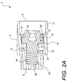
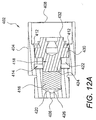
- the key well 14 is configured to carry a biasing element in the form of a coil spring 16 and a key head 18 therein.
- the key well 14 is shown to include a bore 20 and a main guide way 22.
- the bore 20 is adapted to carry the spring 16 and to slideably receive a stem 24 of the key head 18.
- the bore 20 and the stem 24 are optional insofar as the spring 16 could be located in the main guide way 22 and engage a key head configured without a stem.
- the design shown in FIG. 2A ensures proper guidance of the key head 18 by slideably supporting the stem 24 as it interacts with the spring 16.
- the bore 20 and the stem 24 are both shown to be cylindrical in cross-sectional shape, it will be appreciated that other shapes could also be used.
- One end of the bore 20 can be closed by a back wall 26 of the key well 14 in order to support the base of the spring 16.
- an annular ledge (not shown) could be formed to support the spring 16.
- the other end of the bore 20 opens to the main guide way 22.
- the main guide way 22 extends to a key head-receiving opening 28 where the key well 14 meets the ledge 12.
- An enlarged intermediate guide flange portion 30 of the key head 18 slideably engages the sides of the key well's main guide way 22.
- the guide flange 30 and the guide way 22 are both hexagonal in cross-sectional shape. This allows torque to be transferred from the housing 4 to the key head 18, which can then transfer torque to a security fastener through a key pattern to be described below. It will be appreciated that many other configurations could be used to provide the required housing-key head torque transfer, including but not limited to other non-circular cross-sectional configurations, spline configurations, pin configurations, set-screw configurations, to name but a few. Indeed, any configuration that enables the key head 18 to slide within the key well 14 with little or no rotation can be used.
- the other end of the key head 18, which faces the housing's fastener receiving end 8, is provided with a key pattern 32 (best shown in FIG. 1).
- the key pattern 32 is shown by way of example only to be formed as a continuous raised curvilinear projection. However, it should be understood that the key pattern 32 could be implemented using any suitable male (or female) drive configuration that allows the key 2 to impart torque to a security fastener. For example, a continuous recessed curvilinear channel could be used for the key pattern 32.
- Non-continuous drive patterns could also be used, including but not limited to male (or female) pin configurations, slot configurations, star configurations, hexagonal configurations, square configurations, to name but a few.
- FIG. 2A shows one exemplary alternative in which the ledge 12 is staked around the key head-receiving opening 28 in order to trap the key head by engaging its guide flange 30.
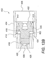
- FIG. 2B shows another construction in which the guide flange 30 is trapped by a retaining ring 34 seated in an annular groove 36 located adjacent to the key head-receiving opening 28.
- the key head 18 is in an operational extension position in which the key pattern 32 is extended toward the housing's fastener-receiving end 8 by virtue of the spring 16.
- the key 2 is maneuvered into alignment with the head of a security fastener 36 and advanced onto the fastener using the shroud 10 as a guide.
- slight rotation of the key 2 may be required to bring the key into proper operational alignment with the security fastener 36.
- the security fastener 36 can be of any desired type, including but not limited to a vehicular lug nut or lug bolt, a vehicular spare tire winch drive, etc.
- the security fastener 36 could also be a non-vehicular fastener.
- the security fastener 36 of FIGS. 3 and 4A-4B is a tubular shroud 38 that freely spins relative to the remainder of the security fastener if an attempt is made to engage the shroud with a gripping tool.
- the security fastener 36 further includes a lock pattern 40 formed as a continuous curvilinear key receiving groove in the security fastener's generally planar end face 42. A raised curvilinear projection could also be used if the key pattern 32 is formed as a recessed curvilinear channel. Other lock pattern configurations will be required if other key pattern configurations are used. Note that in FIGS. 3 and 4A, the lock pattern 40 is assumed to match the key pattern 32.
- FIG. 4B shows the key 2 being used with a security fastener 36A having a non-matching lock pattern 40A.
- the lock pattern 40 is configured to mate with the key pattern 32, the key pattern in an operational extension position will substantially engage the lock pattern when the key 2 is advanced onto the security fastener 36, thereby allowing the security fastener to be operated by way rotation thereof under torque applied by the key.
- the security fastener 36 is a vehicular lug nut or lug bolt
- the key 2 can be used to turn the security fastener into and out of locking engagement in a vehicle wheel installation in which a vehicle wheel (not shown) is secured to a hub or other mounting structure (not shown).
- FIG. 4B it is assumed that an attempt has been made to use the key 2 on a security fastener 36A whose lock pattern 40A is not configured to mate with the key pattern 32. In that case, the key pattern 32 in an operational extension position will not engage the lock pattern 40A and the non-matching security fastener 36A cannot be operated by the key 2. If an attempt is made to jam the key 2 onto the non-matching security fastener 36A by applying an excessive tampering force (e.g., due to a hammer blow delivered to the base 6 of the key 2), the tampering force will be reacted by the immovable end face 42A of the security fastener against the key pattern 32.
- an excessive tampering force e.g., due to a hammer blow delivered to the base 6 of the key 2
- This tampering force will tend to urge the key head 18 toward the back wall 26 of the key well 14 against the biasing force of the spring 16.
- the key pattern 32 cannot be forced into engagement with the non-matching security fastener 36A.
- the key pattern 32 will simply retract toward the key well 14 into a non-operational retraction position.
- the spring 16 will act as a retraction control member that controls retraction of the key pattern 32 according to the amount of tampering force that is applied. Note that the spring 16 will return the key pattern 32 to an operational extension position once the tampering force is removed.
- the non-operational retraction position is only temporary in the first exemplary key construction represented by the key 2.
- the spring 16 should be designed so that forces associated with normal use of the key 2 to operate an authorized matching security fastener will not appreciably deflect the spring. However, the spring 16 should yield under the higher tampering force. Implementing the spring 16 as a helical coil made from steel stock of suitable gauge thickness will allow the key 2 to operate in the manner described above. It should further be understood that other spring designs may likewise be used to provide the biasing force needed for the key head retraction control function, including but not limited to Belleville spring washers as well as other biasing elements made from deformable resilient materials such as compressible rubber or the like. Resilient cushions, such as gas-filled bladders, could also be used.
- a stop surface can be associated with the key housing 4 to contact an area of the non-matching security fastener 36A as the key pattern 32 retracts. This will prevent the security fastener's non-matching lock pattern 40A from following the key pattern 32 to its retraction limit wherein the key head 18 bottoms out in the key well 14.
- the stop surface may reside at various locations on the key 2 depending on the geometry of the key and the size and shape of the non-matching security fastener 36A. For example, as shown in FIG.
- a stop surface may be provided by the housing's fastener receiving end 8 if the shroud 10 is present and is of sufficient length to engage a corresponding surface of the non-matching security fastener 36A during retraction of the key pattern 32.
- this corresponding surface is located on the front face of a tapered seat member of the non-matching security fastener 36A. If the shroud 10 is not present, or is of reduced length, or if the security fastener 36A has no surface to contact the shroud, the ledge 12 of the housing 4 can act as a stop surface that engages (for example) the forward end face of the non-matching security fastener's tubular shroud 38A as the key pattern 32 retracts.
- the fastener receiving end 8 and the ledge 12 of the key 2 could both act as stop surfaces in different situations depending on the type of non-matching security fastener being contacted by the key.
- some key constructions may provide plural application-specific stop surfaces.
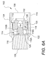
- a key 102 according to a second exemplary key construction of the invention is similar in many respects to the key 2 of the first exemplary key construction, as indicated by the use of corresponding reference numbers incremented by a value of 100.
- the primary difference between the key 202 and the key 2 is that the former does not use the spring 16 as a retraction control member. Instead, the spring 16 is replaced with a breakable element 116 made from plastic (e.g., ST801 type 6/6 polyamide nylon or the like) or other readily breakable material, such as soft metal, etc.
- the housing 104 is modified such that the key well 114 comprises only a primary guide way 122 of hexagonal cross-sectional shape. It does not include a separate bore such as the bore 20 in the key housing 4 described above.
- the key head 118 is also modified insofar as it lacks a stem.
- the breakable element 116 is formed with a disk-shaped base flange 116A that rests against the back wall 126 of the key well 114. Extending from the base flange 116A is a central post 116B that is sized to mate with a central longitudinal bore 118A formed in the key head 118. A thin, disk-shaped key pattern support flange 116C is mounted on the post 116B in spaced relation to the base flange 116A. The support flange 116C engages a base end of the key head to limit the distance that the post 116B penetrates into the bore 118A.
- the breakable element 116 thus acts as a retraction control member that maintains the key pattern 132 in an operational extension position until a tampering force is applied. More particularly, the thickness of the support flange 116C is controlled to shear, rip, rupture or tear from the post 116B, and/or to bend or fold, when a desired breakaway force is applied. It will be appreciated that a higher breakaway force can be obtained by increasing the thickness of the support flange 116C, and visa versa.
- FIG. 6B it is assumed that a tampering force has been applied to the key pattern 132, and that the support flange 116C has sheared at its point of connection to the post 116B. This allows the post 116B to advance into the bore 118A, enabling the key head 118 to slide toward the back of the key well 114. The key pattern 132 will thereby retract to a non-operational retraction position. Note that because the breakable element 116 is used in lieu of a biasing element, the key pattern 132 will tend to remain in a retraction position after the tampering force is removed, rendering the key 102 inoperable even for authorized use with a matching security fastener.
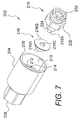
- a key 202 according to a third exemplary key construction of the invention is similar in many respects to the key 102 of the second exemplary key construction, as indicated by the use of corresponding reference numbers incremented by a value of 100.
- the primary difference between the key 202 and the key 102 is in the design of the retraction control member.
- a modified breakable element 216 made from plastic (e.g., ST801 type 6/6 polyamide nylon or the like) or other readily breakable material, such as soft metal, etc., is used in lieu of the breakable element 116 described above.
- the housing 204 is the same design used for the housing 4 of the first exemplary key construction.
- the key well 214 of the housing 204 thus includes both a bore 220 and a main guide way 222.
- the key head 218 is similar to the key head 18 of the first exemplary key construction, except that it includes a post 218A extending from the stem 224.
- the breakable element 216 is formed with a main bushing 216A that is sized to slideably engage the sides of the key well bore 220.
- a thin, disk-shaped key pattern support flange 216B is mounted on the end of the main bushing 216A that faces the key well's main guide way 222.
- the support flange 216B engages the back of the key well's main guide way 222.
- a central bore 216C in the breakable element 216 extends through the main bushing 216A (or at least a portion thereof).
- the central bore 216C is sized to receive the key head's post 218A.
- the breakable element 216 thus acts as a retraction control member that maintains the key pattern 232 in an operational extension position until a tampering force is applied. More particularly, the thickness of the support flange 216B is controlled to shear, rip, rupture or tear from the main bushing 216A, and/or to bend or fold, when a desired breakaway force is applied. It will be appreciated that a higher breakaway force can be obtained by increasing the thickness of the support flange 216B, and visa versa.
- FIG. 8B it is assumed that a tampering force has been applied to the key pattern 232, and that the support flange 216B has sheared at its point of connection to the main bushing 216A. This will allow the main bushing 216A to retreat deeper into key well's bore 220, enabling the key head 218 to slide toward the back of the key well 214. The key pattern 232 will thereby retract to a non-operational retraction position. Note that because the breakable element 216 is used in lieu of a biasing element, the key pattern 232 will tend to remain in a retraction position after the tampering force is removed, rendering the key 202 inoperable even for authorized use with a matching security fastener.
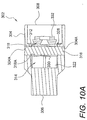
- a key 302 according to a fourth exemplary key construction of the invention is similar in many respects to the key 202 of the third exemplary key construction, as indicated by the use of corresponding reference numbers incremented by a value of 100.
- the primary difference between the key 302 and the key 202 is in the design of the retraction control member.
- the housing 304 is the same design used for the housing 104 of the second exemplary key construction, except that there are a pair of opposing pin-receiving holes 304A formed in the sides of the key well 314.
- the key head 318 is similar to the key head 118 of the second exemplary key construction, except that there is no longitudinal bore. Instead, a transverse bore 318A can be prodded to extend laterally through the key head's guide flange 330.
- the breakable element 316 is formed as a pin that extends through the holes 304A in the key housing 304 and which may also extend through the key head bore 318A, if present.
- the breakable element 316 could be located behind the key head's guide flange 330, in which case the key head bore 318A is not required.
- the breakable element 316 acts as a retraction control member that maintains the key pattern 332 in an operational extension position until a tampering force is applied.
- the thickness of the breakable element 316 is controlled to shear, rip, rupture or tear, and/or to bend or fold, in two places on opposite sides of the key head 318 (i.e., at the location of the holes 304A) when a desired breakaway force is applied. It will be appreciated that a higher breakaway force can be obtained by increasing the thickness of the breakable element 316, and visa versa.
- FIG. 10B it is assumed that a tampering force has been applied to the key pattern 332, and that the breakable element 316 has sheared in the manner described above. This will allow the key head 318 to slide toward the back of the key well 314. The key pattern 332 will thereby retract to a non-operational retraction position. Note that because the breakable element 316 is used in lieu of a biasing element, the key pattern 332 will tend to remain in a retraction position after the tampering force is removed, rendering the key 302 inoperable even for authorized use with a matching security fastener.
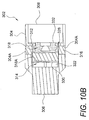
- a key 402 according to a fifth exemplary key construction of the invention is similar in many respects to the key 302 of the second exemplary key construction, as indicated by the use of corresponding reference numbers incremented by a value of 100.
- the primary difference between the key 402 and the key 302 is in the design of the retraction control member.
- a crushable element 416 made from a relatively rigid yet collapsible foam, or other readily crushable material, is used in lieu of a breakable element.
- the housing 404 is the same design used for the housing 4 of the first exemplary key construction.
- the key well 414 of the housing 404 thus includes both a bore 420 and a main guide way 422.
- the key head 418 is the same design used for the key head 18 of the first exemplary key construction, and thus includes a stem 424.
- the crushable element 416 is shaped as a cylinder and resides within the key well's bore 420. One end of the crushable element 416 is seated against the key well's back wall 426. The other end of the crushable element 416 bears against the end face of the key head's stem 424 and supports the key head 418 against slideable movement toward the back of the key well 414.
- the crushable element 416 thus acts as a retraction control member that maintains the key pattern 432 in an operational extension position until a tampering force is applied.
- the crushable element 416 when a tampering force is applied to the key pattern 432, the crushable element 416 will collapse within the bore 420. This will allow the key head 418 to slide toward the back of the key well 414. The key pattern 432 will thereby retract to a non-operational retraction position. Note that because the crushable element 416 is used in lieu of a biasing element, the key pattern 432 will tend to remain in a retraction position after the tampering force is removed, rendering the key 402 inoperable even for authorized use with a matching security fastener.
- a key with a retractable key pattern has been shown and described according to several exemplary constructions. While various embodiments have been disclosed, many other variations would also be possible within the scope of the invention. For example, although various designs for implementing a retraction control function have been set forth, it should be apparent to persons skilled in the art in light of the teachings herein that there are innumerable design alternatives that could also be used. Examples include but are not limited to the use of retention elements that operate along the sides of the key well, such as ball detent mechanisms, deformable or breakable retaining rings or bushings, and flanges that are either separately attached or integrally formed on the key head or the key well, etc. Another design approach would be to establish an interference fit between the key head and the sides of the key well.
- Obtaining a proper interference fit with the required breakaway force could be aided by providing knurling on the key head or the key well, providing a deformable bushing between the key head and the key well, or by forming the stem of the key head as a slotted tube that is compressed by the key well side walls (or by an insert in the key well). Tapering the key well side walls or forming a chamfer therein (or providing a tapered or chamfered insert in the key well) could be used to apply a compressive force on the key head that increases as the key pattern retracts.
Landscapes
- Engineering & Computer Science (AREA)
- General Engineering & Computer Science (AREA)
- Mechanical Engineering (AREA)
- Lock And Its Accessories (AREA)
- Fittings On The Vehicle Exterior For Carrying Loads, And Devices For Holding Or Mounting Articles (AREA)
- Walking Sticks, Umbrellas, And Fans (AREA)
Claims (32)
- Schlüssel (2, 102, 202, 303 oder 402) zum Betätigen eines Sicherheitsverschlusses (36), der ein Verriegelungsmuster (40) besitzt, wobei der Schlüssel ein Gehäuse (4, 104, 204, 304 oder 404) besitzt, das ein Basisende (6, 106, 206, 306 oder 406) und ein offenes, eine Befestigungseinrichtung aufnehmendes Ende (8, 108, 208, 308 oder 408), eine Schlüsselvertiefung (14, 114, 214, 314 oder 414) in dem Gehäuse und ein Schlüsselmuster (32, 132, 232, 332 oder 432) in der Schlüsselvertiefung besitzt, gekennzeichnet durch:eine ein Drehmoment aufnehmende Anordnung, die dem Gehäusebasisende zugeordnet ist, wobei die das Drehmoment aufnehmende Anordnung so angepasst ist, um ein Rotationsdrehmoment von einer Drehmomentquelle auf das Gehäuse zu übertragen;eine Drehmomentübertragungsanordnung zwischen der Schlüsselvertiefung und dem Schlüsselmuster, wobei die Drehmomentübertragungsanordnung so angepasst ist, um ein Rotationsdrehmoment, aufgebracht durch die Drehmomentquelle, auf das Gehäuse von dem Gehäuse zu dem Schlüsselmuster zu übertragen; undwobei das Schlüsselmuster gleitend in der Schlüsselvertiefung angeordnet ist und von einer betriebsmäßigen Verlängerungsposition, in der das Schlüsselmuster für einen im Wesentlichen Eingriff mit der Sicherheitsbefestigungseinrichtung (36), die ein passendes Verriegelungsmuster (40) besitzt, freigegeben ist, um dadurch einen Betrieb der passenden Sicherheitsbefestigungseinrichtung zuzulassen, und einer nicht betriebsmäßigen Rückziehposition, in der das Schlüsselmuster nicht in der Lage für einen wesentlichen Eingriff mit einer Sicherheitsbefestigungseinrichtung (36A), die ein nicht passendes Verriegelungsmuster (40A) besitzt, ist, um dadurch einen Betrieb der nicht passenden Sicherheitsbefestigungseinrichtung zu verhindern.
- Schlüssel nach Anspruch 1, der weiterhin ein Rückziehkontrallelement (16, 116, 216, 316 oder 416) umfasst, das so angepasst ist, um einer Bewegung des Schlüsselmusters von der Verlängerungsposition zu der Rückziehposition zu widerstehen, bis eine Sabotagekraft über eine normale Betätigungskraft hinaus auf das Schlüsselmuster aufgebracht wird.
- Schlüssel nach Anspruch 2, wobei das Rückziehkontrollelement ein Vorspannelement (16) aufweist.
- Schlüssel nach Anspruch 2, wobei das Rückziehkontrollelement ein zerbrechbares Element (116, 216 oder 316) aufweist.
- Schlüssel nach Anspruch 4, wobei das zerbrechbare Element einen zerbrechbaren Schlüsselmuster-Trageflansch (116 oder 216) aufweist.
- Schlüssel nach Anspruch 4, wobei das zerbrechbare Element einen zerbrechbaren Schlüsselmuster-Tragestift (316) aufweist.
- Schlüssel nach Anspruch 2, wobei das Rückziehkontrollelement ein quetschbares Element (418) aufweist.
- Schlüssel nach Anspruch 1, wobei:das Schlüsselmuster an einem Ende eines Schlüsselkopfs (18, 118, 218, 318 oder 418), gleitbar angeordnet in der Schlüsselvertiefung, angeordnet ist; undder Schlüsselkopf ein gegenüberliegendes Ende aufweist, das zu dem Gehäusebasisende hinweist, wobei die Endfläche frei von einer ein Drehmoment aufnehmenden Schaftstruktur ist, die sich über das Gehäusebasisende hinaus erstreckt.
- Schlüssel nach Anspruch 8, der weiterhin ein Rückziehkontrollelement (16, 116, 216, 316 oder 416) aufweist, das so angepasst ist, um einer Bewegung des Schlüsselmusters von der Verlängerungsposition zu der Rückziehposition zu widerstehen, bis eine Sabotagekraft über eine normale Betätigungskraft hinaus auf das Schlüsselmuster aufgebracht ist.
- Schlüssel nach Anspruch 9, wobei das Rückzishkontrollslsment ein Vorspannelement (16) aufweist, das zwischen der Schlüsselvertiefung (14) und dem Schlüsselkopf (18) angeordnet ist.
- Schlüssel nach Anspruch 3 oder 10, wobei das Vorspannelement eine Feder (16) aufweist.
- Schlüssel nach Anspruch 3 oder 10, wobei das Vorspannelement ein deformierbares, elastisches Material (16) aufweist.
- Schlüssel nach Anspruch 9, wobei das Rückziehkontrollelement ein zerbrechbares Element (116, 216 oder 316), angeordnet zwischen der Schlüsselvertiefung (114, 214 oder 324) und dem Schlüsselkopf (118, 218 oder 318), aufweist.
- Schlüssel nach Anspruch 13, wobei das zerbrechbare Element einen zerbrechbaren Schlüsselmuster-Trageflansch (116C oder 216B) aufweist.
- Schlüssel nach Anspruch 14, wobei das zerbrechbare Element einen Stab (116B) aufweist, der sich in eine Öffnung (118A) in dem Schlüsselkopf hinein erstreckt, wobei der Schlüsselkopf so angepasst ist, um auf der Säule zu gleiten, während sich das Schlüsselmuster zu der Rückziehposition bewegt, nachdem der Trageflansch gebrochen oder in anderer Weise beeinträchtigt ist.
- Schlüssel nach Anspruch 14, wobei das zerbrechbare Element eine Buchse (216A) aufweist, die den Trageflansch (216B) befestigt und so angepasst ist, um in die Schlüsselvertiefung zu gleiten, während sich das Schlüsselmuster zu der Rückziehposition bewegt, nachdem der Trageflansch gebrochen oder in sonstiger Weise beeinträchtigt ist.
- Schlüssel nach Anspruch 16, wobei die Buchse eine Öffnung (216C) aufweist, die einen Schaft (218A) an dem Schlüsselkopf aufnimmt.
- Schlüssel nach Anspruch 13, wobei das zerbrechbare Element einen zerbrechbaren Stift (316) aufweist, der sich quer durch Öffnungen (304A) in dem Gehäuse und entweder angrenzend an den Schlüsselkopf oder durch eine Öffnung (318A) in dem Schlüsselkopf erstreckt.
- Schlüssel nach Anspruch 9, wobei die Schlüsselvertiefung mit einem geschlossenen Ende versehen ist und das Rückziehkontrollelement ein quetschbares Element (416) aufweist, das zwischen einem geschlossenen Ende der Schlüsselvertiefung und dem Schlüsselkopf angeordnet ist.
- Schlüssel nach Anspruch 2 oder 9, wobei das Rückziehkontrollelement so angepasst ist, um das Schlüsselmuster von der Rückziehposition zu der Verlängerungsposition zurückzuführen, nachdem die Sabotagekraft weggenommen ist.
- Schlüssel nach einem der vorhergehenden Ansprüche, der weiterhin eine Anschlagfläche (8, 12, 108,112, 208. 212, 308, 312,408 oder 412) aufweist, angepasst so, um eine Fläche einer nicht passenden Sicherheitsbefestigungseinrichtung zu berühren, wenn sich das Schlüsselmuster zu der Rückziehposition zurückzieht.
- Schlüssel nach Anspruch 21, wobei das Gehäuse eine Ummantelung (10, 110, 210, 310 oder 410) aufweist, die die Anschlagfläche bildet.
- Schlüssel nach Anspruch 21, wobei die Anschlagfläche durch einen Vorsprung (12, 112, 212, 31Z oder 412) gebildet ist, der sich im Wesentlichen quer von einer Kante der Schlüsselvertiefung aus erstreckt.
- Schlüssel nach Anspruch 21, wobei der Schlüssel eine Mehrzahl von Anschlagoberflächen (8, 12, 108, 112, 208, 212, 308, 312, 408 oder 412) aufweist.
- Schlüssel nach einem der Ansprüche 8 bis 24, wobei der Schlüsselkopf in der Schlüsselvertiefung durch Anbinden (33) eines Kantenbereichs der Schlüsselvertiefung zurückgehalten ist.
- Schlüssel nach einem der Ansprüche 8 bis 25, wobei der Schlüsselkopf in der Schlüsselvertiefung durch eine Rückhalteklammer (34), angeordnet in der Nähe eines Kantenbereichs der Schlüsselvertiefung, gehalten ist.
- Schlüssel nach einem der Ansprüche 8 bis 26, wobei die Schlüsselvertiefung und der Schlüsselkopf gegenseitig gleitbare Oberflächenbereiche (30/22, 130/122, 230/222, 330/322 oder 430/422) aufweisen, die so geformt sind, um eine Drehung des Schlüsselkopfs in der Schlüsselvertiefung zu verhindern.
- Schlüssel nach einem der Ansprüche 8 bis 27, wobei das Gehäuse ein Basisende (6, 106, 206, 306 oder 406) aufweist, das so angepasst ist, um einen Griff oder ein Werkzeug aufzunehmen.
- Schlüssel nach Anspruch 28, wobei das Gehäusebasisende entweder eine vorspringende oder zurückspringende Antriebskonfiguration aufweist.
- Schlüssel nach einem der vorhergehenden Ansprüche, wobei das Schlüsselmuster für die Verwendung mit einer Fahrzeugsicherheits-Befestigungseinrichtung aufgebaut ist.
- Schlüssel nach einem der vorhergehenden Ansprüche, wobei das Schlüsselmuster zur Verwendung mit einer nicht fahrzeugmäl3igen Sicherheitsbefestigungseinrichtung aufgebaut ist.
- Schlüssel nach einem der vorhergehenden Ansprüche, wobei das Schlüsselmuster entweder ein vorspringendes oder ein zurückspringendes, kontinuierliches oder nicht kontinuierliches, gekrümmtes oder nicht gekrümmtes Muster oder eine Antriebskonfiguration aufweist.
Applications Claiming Priority (2)
| Application Number | Priority Date | Filing Date | Title |
|---|---|---|---|
| US10/736,221 US7036405B2 (en) | 2003-12-15 | 2003-12-15 | Key with retractable pattern |
| US736221 | 2003-12-15 |
Publications (3)
| Publication Number | Publication Date |
|---|---|
| EP1544483A1 EP1544483A1 (de) | 2005-06-22 |
| EP1544483B1 true EP1544483B1 (de) | 2006-08-23 |
| EP1544483B8 EP1544483B8 (de) | 2006-10-11 |
Family
ID=34523119
Family Applications (1)
| Application Number | Title | Priority Date | Filing Date |
|---|---|---|---|
| EP04254022A Expired - Lifetime EP1544483B8 (de) | 2003-12-15 | 2004-07-02 | Schlüssel mit zurückziehbarer Ausbildung |
Country Status (4)
| Country | Link |
|---|---|
| US (1) | US7036405B2 (de) |
| EP (1) | EP1544483B8 (de) |
| AT (1) | ATE337497T1 (de) |
| DE (1) | DE602004002079T2 (de) |
Families Citing this family (14)
| Publication number | Priority date | Publication date | Assignee | Title |
|---|---|---|---|---|
| US20090129887A1 (en) * | 2007-11-19 | 2009-05-21 | Chang Peter J H | Screw kit |
| US7587799B2 (en) * | 2007-12-19 | 2009-09-15 | Yu Hsin Li | Installation tool for helical coil inserts |
| FR2930608B1 (fr) * | 2008-04-23 | 2010-05-14 | Forges De Froncles Soc D | Dispositif de fixation antivol de solidarisation d'une roue sur le moyeu d'un vehicule automobile |
| KR20130014548A (ko) | 2010-03-08 | 2013-02-07 | 에어로바이론먼트, 인크. | 단리식 케이블 커넥터 |
| GB201004187D0 (en) * | 2010-03-15 | 2010-04-28 | Wells Patrick | Security fastener |
| US8525653B1 (en) * | 2010-04-29 | 2013-09-03 | Wayne A. Bing | Anti-theft system for wheels and rims |
| WO2015200053A1 (en) * | 2014-06-23 | 2015-12-30 | Mcgard Llc | Security lock with deformable latch |
| US11234899B2 (en) * | 2017-05-11 | 2022-02-01 | Scalpal Llc | Grasping facilitators and uses thereof and kits involving the same |
| US11969864B2 (en) | 2017-05-11 | 2024-04-30 | Scalpal Llc | Multi-tier torque enhancer driver and/or receiver and method of using same |
| CA3018874A1 (en) * | 2018-09-27 | 2020-03-27 | Terry Whittleton | Socket wrench extension for use with a ratchet in the oil field |
| GB2578578A (en) * | 2018-10-30 | 2020-05-20 | Auto Turned Products Northants Ltd | Locking fixing and key body |
| MX2019005377A (es) * | 2019-05-08 | 2019-10-07 | Gildardo Blanco Barrera Gudalupe | Dispositivo de seguridad para medios de rodamiento de vehiculos. |
| USD1050836S1 (en) * | 2022-11-28 | 2024-11-12 | Gunnersbury Global Trade Limited | Security nut driver for wheels |
| USD1084805S1 (en) | 2023-09-28 | 2025-07-22 | Gunnersbury Global Trade, Ltd. | Fastening device |
Family Cites Families (10)
| Publication number | Priority date | Publication date | Assignee | Title |
|---|---|---|---|---|
| US2698637A (en) * | 1952-06-12 | 1955-01-04 | Ludwig Hommel & Co | Screw driver bit with pilot sleeve |
| US3288185A (en) * | 1965-01-15 | 1966-11-29 | Wade Stevenson | Screwdriver construction |
| US3739825A (en) * | 1971-10-06 | 1973-06-19 | Vermont American Corp | Screwdriver |
| US4130152A (en) * | 1977-10-19 | 1978-12-19 | John Sawyer | Slot-head fastener and driver therefor |
| US4648293A (en) * | 1983-06-10 | 1987-03-10 | Mcgard, Inc. | Locknut and key therefor |
| US4618299A (en) * | 1984-03-07 | 1986-10-21 | Mcgard, Inc. | Locknut and key therefor |
| US4848113A (en) * | 1988-05-23 | 1989-07-18 | Mcgard, Inc. | Spare wheel lock construction |
| US4875819A (en) * | 1988-10-11 | 1989-10-24 | Kevin Wilkinson | Wheel lock system apparatus |
| US6161456A (en) * | 1997-11-26 | 2000-12-19 | Langford; Don C. | Shielded spike tool |
| US6719511B2 (en) * | 2002-03-01 | 2004-04-13 | Mcgard, Inc. | High security fastener constructions |
-
2003
- 2003-12-15 US US10/736,221 patent/US7036405B2/en not_active Expired - Lifetime
-
2004
- 2004-07-02 EP EP04254022A patent/EP1544483B8/de not_active Expired - Lifetime
- 2004-07-02 DE DE602004002079T patent/DE602004002079T2/de not_active Expired - Lifetime
- 2004-07-02 AT AT04254022T patent/ATE337497T1/de not_active IP Right Cessation
Also Published As
| Publication number | Publication date |
|---|---|
| DE602004002079D1 (de) | 2006-10-05 |
| US20050126349A1 (en) | 2005-06-16 |
| ATE337497T1 (de) | 2006-09-15 |
| EP1544483A1 (de) | 2005-06-22 |
| US7036405B2 (en) | 2006-05-02 |
| DE602004002079T2 (de) | 2007-01-11 |
| EP1544483B8 (de) | 2006-10-11 |
Similar Documents
| Publication | Publication Date | Title |
|---|---|---|
| EP1544483B1 (de) | Schlüssel mit zurückziehbarer Ausbildung | |
| US7351020B1 (en) | High security fastener constructions | |
| US7445414B1 (en) | High security fastener constructions | |
| US5647253A (en) | Method and apparatus for a theft resistant fastener | |
| US6568894B2 (en) | Fastener devices, such as lock-pins | |
| US10816028B2 (en) | Method of forming high security fastener with internal shroud buckled retainer | |
| US7066062B2 (en) | Torque-setting, tamper-resistant fastener and method and tool for use with same | |
| JP3012803B2 (ja) | エアバッグの取り付けシステム | |
| US20020014137A1 (en) | Screw device and assembly for theft-proofing vehicle wheels | |
| KR0148026B1 (ko) | 조향핸들 체결용 자동차 도난방지 장치 | |
| US4809569A (en) | Anti-theft system for articles secured by recessed socket head threaded fasteners | |
| AU2024202714B2 (en) | Indexable trim tool | |
| GB2460764A (en) | Anti-theft locking device for fastening a motor-vehicle wheel | |
| US6908126B2 (en) | Enhanced security catch assembly for retaining a handle on a spindle | |
| US5127289A (en) | Wrench for hexagonal regular nuts and locknuts | |
| US1801977A (en) | Tire lock | |
| EP1544064B1 (de) | Fahrzeugdiebstahlsicherheitsvorrichtung | |
| US3112637A (en) | Lock and key construction | |
| GB2276133A (en) | Vehicle anti-theft device | |
| US12564919B2 (en) | Manual impact driver | |
| US20240167500A1 (en) | Locking System | |
| EP1434945B1 (de) | Verriegelungsvorrichtung für einen radbolzen | |
| WO1997002435A1 (en) | Theft deterrent device | |
| US20070036631A1 (en) | Draw key assembly for securing a kingpin | |
| KR200156224Y1 (ko) | 차량용 라디오 도난방지 스크류 |
Legal Events
| Date | Code | Title | Description |
|---|---|---|---|
| PUAI | Public reference made under article 153(3) epc to a published international application that has entered the european phase |
Free format text: ORIGINAL CODE: 0009012 |
|
| 17P | Request for examination filed |
Effective date: 20050323 |
|
| AK | Designated contracting states |
Kind code of ref document: A1 Designated state(s): AT BE BG CH CY CZ DE DK EE ES FI FR GB GR HU IE IT LI LU MC NL PL PT RO SE SI SK TR |
|
| AX | Request for extension of the european patent |
Extension state: AL HR LT LV MK |
|
| 17Q | First examination report despatched |
Effective date: 20050523 |
|
| GRAP | Despatch of communication of intention to grant a patent |
Free format text: ORIGINAL CODE: EPIDOSNIGR1 |
|
| RAP1 | Party data changed (applicant data changed or rights of an application transferred) |
Owner name: MCGARD, INC. |
|
| AKX | Designation fees paid |
Designated state(s): AT BE BG CH CY CZ DE DK EE ES FI FR GB GR HU IE IT LI LU MC NL PL PT RO SE SI SK TR |
|
| GRAS | Grant fee paid |
Free format text: ORIGINAL CODE: EPIDOSNIGR3 |
|
| GRAA | (expected) grant |
Free format text: ORIGINAL CODE: 0009210 |
|
| AK | Designated contracting states |
Kind code of ref document: B1 Designated state(s): AT BE BG CH CY CZ DE DK EE ES FI FR GB GR HU IE IT LI LU MC NL PL PT RO SE SI SK TR |
|
| PG25 | Lapsed in a contracting state [announced via postgrant information from national office to epo] |
Ref country code: NL Free format text: LAPSE BECAUSE OF FAILURE TO SUBMIT A TRANSLATION OF THE DESCRIPTION OR TO PAY THE FEE WITHIN THE PRESCRIBED TIME-LIMIT Effective date: 20060823 Ref country code: CH Free format text: LAPSE BECAUSE OF FAILURE TO SUBMIT A TRANSLATION OF THE DESCRIPTION OR TO PAY THE FEE WITHIN THE PRESCRIBED TIME-LIMIT Effective date: 20060823 Ref country code: AT Free format text: LAPSE BECAUSE OF FAILURE TO SUBMIT A TRANSLATION OF THE DESCRIPTION OR TO PAY THE FEE WITHIN THE PRESCRIBED TIME-LIMIT Effective date: 20060823 Ref country code: IT Free format text: LAPSE BECAUSE OF FAILURE TO SUBMIT A TRANSLATION OF THE DESCRIPTION OR TO PAY THE FEE WITHIN THE PRESCRIBED TIME-LIMIT;WARNING: LAPSES OF ITALIAN PATENTS WITH EFFECTIVE DATE BEFORE 2007 MAY HAVE OCCURRED AT ANY TIME BEFORE 2007. THE CORRECT EFFECTIVE DATE MAY BE DIFFERENT FROM THE ONE RECORDED. Effective date: 20060823 Ref country code: SI Free format text: LAPSE BECAUSE OF FAILURE TO SUBMIT A TRANSLATION OF THE DESCRIPTION OR TO PAY THE FEE WITHIN THE PRESCRIBED TIME-LIMIT Effective date: 20060823 Ref country code: SK Free format text: LAPSE BECAUSE OF FAILURE TO SUBMIT A TRANSLATION OF THE DESCRIPTION OR TO PAY THE FEE WITHIN THE PRESCRIBED TIME-LIMIT Effective date: 20060823 Ref country code: CZ Free format text: LAPSE BECAUSE OF FAILURE TO SUBMIT A TRANSLATION OF THE DESCRIPTION OR TO PAY THE FEE WITHIN THE PRESCRIBED TIME-LIMIT Effective date: 20060823 Ref country code: BE Free format text: LAPSE BECAUSE OF FAILURE TO SUBMIT A TRANSLATION OF THE DESCRIPTION OR TO PAY THE FEE WITHIN THE PRESCRIBED TIME-LIMIT Effective date: 20060823 Ref country code: RO Free format text: LAPSE BECAUSE OF FAILURE TO SUBMIT A TRANSLATION OF THE DESCRIPTION OR TO PAY THE FEE WITHIN THE PRESCRIBED TIME-LIMIT Effective date: 20060823 Ref country code: PL Free format text: LAPSE BECAUSE OF FAILURE TO SUBMIT A TRANSLATION OF THE DESCRIPTION OR TO PAY THE FEE WITHIN THE PRESCRIBED TIME-LIMIT Effective date: 20060823 Ref country code: FI Free format text: LAPSE BECAUSE OF FAILURE TO SUBMIT A TRANSLATION OF THE DESCRIPTION OR TO PAY THE FEE WITHIN THE PRESCRIBED TIME-LIMIT Effective date: 20060823 Ref country code: LI Free format text: LAPSE BECAUSE OF FAILURE TO SUBMIT A TRANSLATION OF THE DESCRIPTION OR TO PAY THE FEE WITHIN THE PRESCRIBED TIME-LIMIT Effective date: 20060823 |
|
| REG | Reference to a national code |
Ref country code: GB Ref legal event code: FG4D |
|
| REG | Reference to a national code |
Ref country code: CH Ref legal event code: EP |
|
| RAP2 | Party data changed (patent owner data changed or rights of a patent transferred) |
Owner name: MCGARD, LLC. |
|
| REG | Reference to a national code |
Ref country code: IE Ref legal event code: FG4D |
|
| REF | Corresponds to: |
Ref document number: 602004002079 Country of ref document: DE Date of ref document: 20061005 Kind code of ref document: P |
|
| NLT2 | Nl: modifications (of names), taken from the european patent patent bulletin |
Owner name: MCGARD, LLC. Effective date: 20060920 |
|
| PG25 | Lapsed in a contracting state [announced via postgrant information from national office to epo] |
Ref country code: SE Free format text: LAPSE BECAUSE OF FAILURE TO SUBMIT A TRANSLATION OF THE DESCRIPTION OR TO PAY THE FEE WITHIN THE PRESCRIBED TIME-LIMIT Effective date: 20061123 Ref country code: BG Free format text: LAPSE BECAUSE OF FAILURE TO SUBMIT A TRANSLATION OF THE DESCRIPTION OR TO PAY THE FEE WITHIN THE PRESCRIBED TIME-LIMIT Effective date: 20061123 Ref country code: DK Free format text: LAPSE BECAUSE OF FAILURE TO SUBMIT A TRANSLATION OF THE DESCRIPTION OR TO PAY THE FEE WITHIN THE PRESCRIBED TIME-LIMIT Effective date: 20061123 |
|
| PG25 | Lapsed in a contracting state [announced via postgrant information from national office to epo] |
Ref country code: ES Free format text: LAPSE BECAUSE OF FAILURE TO SUBMIT A TRANSLATION OF THE DESCRIPTION OR TO PAY THE FEE WITHIN THE PRESCRIBED TIME-LIMIT Effective date: 20061204 |
|
| PG25 | Lapsed in a contracting state [announced via postgrant information from national office to epo] |
Ref country code: PT Free format text: LAPSE BECAUSE OF FAILURE TO SUBMIT A TRANSLATION OF THE DESCRIPTION OR TO PAY THE FEE WITHIN THE PRESCRIBED TIME-LIMIT Effective date: 20070125 |
|
| NLV1 | Nl: lapsed or annulled due to failure to fulfill the requirements of art. 29p and 29m of the patents act | ||
| REG | Reference to a national code |
Ref country code: CH Ref legal event code: PL |
|
| EN | Fr: translation not filed | ||
| PLBE | No opposition filed within time limit |
Free format text: ORIGINAL CODE: 0009261 |
|
| STAA | Information on the status of an ep patent application or granted ep patent |
Free format text: STATUS: NO OPPOSITION FILED WITHIN TIME LIMIT |
|
| 26N | No opposition filed |
Effective date: 20070524 |
|
| REG | Reference to a national code |
Ref country code: GB Ref legal event code: 732E |
|
| PG25 | Lapsed in a contracting state [announced via postgrant information from national office to epo] |
Ref country code: MC Free format text: LAPSE BECAUSE OF NON-PAYMENT OF DUE FEES Effective date: 20070731 Ref country code: FR Free format text: LAPSE BECAUSE OF FAILURE TO SUBMIT A TRANSLATION OF THE DESCRIPTION OR TO PAY THE FEE WITHIN THE PRESCRIBED TIME-LIMIT Effective date: 20070511 Ref country code: GR Free format text: LAPSE BECAUSE OF FAILURE TO SUBMIT A TRANSLATION OF THE DESCRIPTION OR TO PAY THE FEE WITHIN THE PRESCRIBED TIME-LIMIT Effective date: 20061124 |
|
| PG25 | Lapsed in a contracting state [announced via postgrant information from national office to epo] |
Ref country code: EE Free format text: LAPSE BECAUSE OF FAILURE TO SUBMIT A TRANSLATION OF THE DESCRIPTION OR TO PAY THE FEE WITHIN THE PRESCRIBED TIME-LIMIT Effective date: 20060823 |
|
| PG25 | Lapsed in a contracting state [announced via postgrant information from national office to epo] |
Ref country code: IE Free format text: LAPSE BECAUSE OF NON-PAYMENT OF DUE FEES Effective date: 20070702 |
|
| PG25 | Lapsed in a contracting state [announced via postgrant information from national office to epo] |
Ref country code: FR Free format text: LAPSE BECAUSE OF FAILURE TO SUBMIT A TRANSLATION OF THE DESCRIPTION OR TO PAY THE FEE WITHIN THE PRESCRIBED TIME-LIMIT Effective date: 20060823 |
|
| PG25 | Lapsed in a contracting state [announced via postgrant information from national office to epo] |
Ref country code: CY Free format text: LAPSE BECAUSE OF FAILURE TO SUBMIT A TRANSLATION OF THE DESCRIPTION OR TO PAY THE FEE WITHIN THE PRESCRIBED TIME-LIMIT Effective date: 20060823 Ref country code: LU Free format text: LAPSE BECAUSE OF NON-PAYMENT OF DUE FEES Effective date: 20070702 |
|
| PG25 | Lapsed in a contracting state [announced via postgrant information from national office to epo] |
Ref country code: HU Free format text: LAPSE BECAUSE OF FAILURE TO SUBMIT A TRANSLATION OF THE DESCRIPTION OR TO PAY THE FEE WITHIN THE PRESCRIBED TIME-LIMIT Effective date: 20070224 Ref country code: TR Free format text: LAPSE BECAUSE OF FAILURE TO SUBMIT A TRANSLATION OF THE DESCRIPTION OR TO PAY THE FEE WITHIN THE PRESCRIBED TIME-LIMIT Effective date: 20060823 |
|
| PGFP | Annual fee paid to national office [announced via postgrant information from national office to epo] |
Ref country code: GB Payment date: 20210609 Year of fee payment: 18 |
|
| PGFP | Annual fee paid to national office [announced via postgrant information from national office to epo] |
Ref country code: DE Payment date: 20210608 Year of fee payment: 18 |
|
| REG | Reference to a national code |
Ref country code: DE Ref legal event code: R119 Ref document number: 602004002079 Country of ref document: DE |
|
| GBPC | Gb: european patent ceased through non-payment of renewal fee |
Effective date: 20220702 |
|
| PG25 | Lapsed in a contracting state [announced via postgrant information from national office to epo] |
Ref country code: GB Free format text: LAPSE BECAUSE OF NON-PAYMENT OF DUE FEES Effective date: 20220702 Ref country code: DE Free format text: LAPSE BECAUSE OF NON-PAYMENT OF DUE FEES Effective date: 20230201 |