EP1544452B2 - Filtre à carburant à deux étages - Google Patents
Filtre à carburant à deux étages Download PDFInfo
- Publication number
- EP1544452B2 EP1544452B2 EP04105333.1A EP04105333A EP1544452B2 EP 1544452 B2 EP1544452 B2 EP 1544452B2 EP 04105333 A EP04105333 A EP 04105333A EP 1544452 B2 EP1544452 B2 EP 1544452B2
- Authority
- EP
- European Patent Office
- Prior art keywords
- filter
- filter stage
- stage
- partially
- fuel
- Prior art date
- Legal status (The legal status is an assumption and is not a legal conclusion. Google has not performed a legal analysis and makes no representation as to the accuracy of the status listed.)
- Expired - Lifetime
Links
- 239000000446 fuel Substances 0.000 title claims description 30
- 239000000463 material Substances 0.000 claims description 28
- XLYOFNOQVPJJNP-UHFFFAOYSA-N water Substances O XLYOFNOQVPJJNP-UHFFFAOYSA-N 0.000 claims description 19
- 239000001913 cellulose Substances 0.000 claims description 7
- 239000003365 glass fiber Substances 0.000 claims description 7
- 229920002678 cellulose Polymers 0.000 claims description 6
- 230000002209 hydrophobic effect Effects 0.000 claims description 6
- 229920001410 Microfiber Polymers 0.000 claims description 3
- 239000004744 fabric Substances 0.000 claims description 3
- 239000003658 microfiber Substances 0.000 claims description 3
- 229920000728 polyester Polymers 0.000 claims description 3
- 229920002994 synthetic fiber Polymers 0.000 claims description 3
- 238000001914 filtration Methods 0.000 claims 1
- 238000000926 separation method Methods 0.000 description 9
- 238000004804 winding Methods 0.000 description 8
- 239000002283 diesel fuel Substances 0.000 description 3
- 239000002245 particle Substances 0.000 description 3
- 230000005484 gravity Effects 0.000 description 2
- 239000011148 porous material Substances 0.000 description 2
- 239000012209 synthetic fiber Substances 0.000 description 2
- 229920003043 Cellulose fiber Polymers 0.000 description 1
- 239000004743 Polypropylene Substances 0.000 description 1
- 239000004809 Teflon Substances 0.000 description 1
- 229920006362 Teflon® Polymers 0.000 description 1
- 150000001252 acrylic acid derivatives Chemical class 0.000 description 1
- 230000004888 barrier function Effects 0.000 description 1
- 238000004581 coalescence Methods 0.000 description 1
- 238000002485 combustion reaction Methods 0.000 description 1
- 238000011109 contamination Methods 0.000 description 1
- 230000007797 corrosion Effects 0.000 description 1
- 238000005260 corrosion Methods 0.000 description 1
- 230000000694 effects Effects 0.000 description 1
- 239000000839 emulsion Substances 0.000 description 1
- 239000000835 fiber Substances 0.000 description 1
- 239000012535 impurity Substances 0.000 description 1
- 238000009434 installation Methods 0.000 description 1
- -1 polypropylene Polymers 0.000 description 1
- 229920001155 polypropylene Polymers 0.000 description 1
- 229920001296 polysiloxane Polymers 0.000 description 1
- 229920001343 polytetrafluoroethylene Polymers 0.000 description 1
- 239000004810 polytetrafluoroethylene Substances 0.000 description 1
- 229920003987 resole Polymers 0.000 description 1
Images
Classifications
-
- B—PERFORMING OPERATIONS; TRANSPORTING
- B01—PHYSICAL OR CHEMICAL PROCESSES OR APPARATUS IN GENERAL
- B01D—SEPARATION
- B01D36/00—Filter circuits or combinations of filters with other separating devices
- B01D36/003—Filters in combination with devices for the removal of liquids
-
- B—PERFORMING OPERATIONS; TRANSPORTING
- B01—PHYSICAL OR CHEMICAL PROCESSES OR APPARATUS IN GENERAL
- B01D—SEPARATION
- B01D27/00—Cartridge filters of the throw-away type
- B01D27/04—Cartridge filters of the throw-away type with cartridges made of a piece of unitary material, e.g. filter paper
- B01D27/06—Cartridge filters of the throw-away type with cartridges made of a piece of unitary material, e.g. filter paper with corrugated, folded or wound material
- B01D27/07—Cartridge filters of the throw-away type with cartridges made of a piece of unitary material, e.g. filter paper with corrugated, folded or wound material having a coaxial stream through the filtering element
-
- B—PERFORMING OPERATIONS; TRANSPORTING
- B01—PHYSICAL OR CHEMICAL PROCESSES OR APPARATUS IN GENERAL
- B01D—SEPARATION
- B01D27/00—Cartridge filters of the throw-away type
- B01D27/14—Cartridge filters of the throw-away type having more than one filtering element
- B01D27/146—Cartridge filters of the throw-away type having more than one filtering element connected in series
- B01D27/148—Cartridge filters of the throw-away type having more than one filtering element connected in series arranged concentrically or coaxially
-
- F—MECHANICAL ENGINEERING; LIGHTING; HEATING; WEAPONS; BLASTING
- F02—COMBUSTION ENGINES; HOT-GAS OR COMBUSTION-PRODUCT ENGINE PLANTS
- F02M—SUPPLYING COMBUSTION ENGINES IN GENERAL WITH COMBUSTIBLE MIXTURES OR CONSTITUENTS THEREOF
- F02M37/00—Apparatus or systems for feeding liquid fuel from storage containers to carburettors or fuel-injection apparatus; Arrangements for purifying liquid fuel specially adapted for, or arranged on, internal-combustion engines
- F02M37/22—Arrangements for purifying liquid fuel specially adapted for, or arranged on, internal-combustion engines, e.g. arrangements in the feeding system
- F02M37/24—Arrangements for purifying liquid fuel specially adapted for, or arranged on, internal-combustion engines, e.g. arrangements in the feeding system characterised by water separating means
-
- F—MECHANICAL ENGINEERING; LIGHTING; HEATING; WEAPONS; BLASTING
- F02—COMBUSTION ENGINES; HOT-GAS OR COMBUSTION-PRODUCT ENGINE PLANTS
- F02M—SUPPLYING COMBUSTION ENGINES IN GENERAL WITH COMBUSTIBLE MIXTURES OR CONSTITUENTS THEREOF
- F02M37/00—Apparatus or systems for feeding liquid fuel from storage containers to carburettors or fuel-injection apparatus; Arrangements for purifying liquid fuel specially adapted for, or arranged on, internal-combustion engines
- F02M37/22—Arrangements for purifying liquid fuel specially adapted for, or arranged on, internal-combustion engines, e.g. arrangements in the feeding system
- F02M37/32—Arrangements for purifying liquid fuel specially adapted for, or arranged on, internal-combustion engines, e.g. arrangements in the feeding system characterised by filters or filter arrangements
- F02M37/34—Arrangements for purifying liquid fuel specially adapted for, or arranged on, internal-combustion engines, e.g. arrangements in the feeding system characterised by filters or filter arrangements by the filter structure, e.g. honeycomb, mesh or fibrous
Definitions
- the invention relates to a two-stage filter, in particular a fuel filter, with at least a first filter stage, which consists at least partially of a hydrophilic material, and at least one downstream arranged second filter stage, which consists at least partially of a hydrophobic material.
- Fuel filters are used, inter alia, in diesel engines to filter out impurities contained in diesel fuel and to separate water from the diesel fuel, to avoid thereby caused disturbances and damage such as contamination or corrosion in the fuel system or inferior combustion in the engine.
- the fuel filter has a housing with a cylindrical filter element receiving cup-shaped lower part.
- the filter insert is formed by a two-stage filter, wherein a first filter stage with a hydrophilic filter material is followed by a second filter stage of a hydrophobic filter material at a small distance. Both filter stages are concentric with each other and arranged directly adjacent to each other or at a small distance from each other and are flowed through radially from outside to inside.
- the first filter stage causes finely divided water contained in the fuel to coalesce into droplets or droplets due to the hydrophilic properties, which are then collected at the hydrophobic second filter stage and deposited by gravity.
- a filter for diesel fuels with a first and a second filter stage known, which are arranged concentrically within a filter housing to each other. While the first filter stage is designed as a winding insert, the second filter stage is arranged in the manner of an inverted basket within the winding insert.
- the fuel to be filtered passes axially from top to bottom through the first filter stage and passes through a space below the filter stages from below into the second filter stage. While in the first filter stage particles are filtered out of the fuel, water is deposited at the second filter stage formed as a tissue.
- the principle of water separation is that the water contained in the fuel coalesces in the first filter stage because of its hydrophilic properties, so that small droplets or drops are formed which are collected and separated in the second filter stage.
- An essential core idea of the invention is that - unlike that of the DE 101 23 190 A1 known fuel filter - due to a comparison with the first filter stage larger flow cross-section of the second filter stage, the flow rate in the second filter stage is reduced compared to the flow rate in the first filter stage. This assists the collection of droplets and droplets that have formed in the hydrophilic first filter stage, and their connection to larger droplets, so that the Wasserabscheidegrad is significantly increased.
- the filter according to the invention has the significant advantage that over conventional filters the degree of separation of water contained in the fuel improved or with respect to conventional filters same degree of separation, the surface of the filter material can be reduced overall.
- the filter stages concentric with each other, wherein the first filter stage at the same height of the filter stages is the inner of the two filter stages, and wherein the filter stages are traversed radially from the inside to the outside.
- the second filter stage is preferably arranged in the axial direction or in the direction of an axis of symmetry of the filter essentially behind the first filter stage. This is advantageous in that the flow cross sections of the filter stages are more freely selectable than with filter stages arranged radially to one another.
- the first filter stage is flowed through substantially axially. It is further preferred that the second filter stage is flowed through radially and particularly preferably from outside to inside. The installation of the filter is then preferably such that the axial direction corresponds substantially to the vertical direction and the radial direction of the horizontal direction, so that separated water in the second filter stage can fall transversely to the flow direction to the bottom of the filter housing.
- the second filter stage has at least one thick filter medium.
- the advantage of a comparatively thick filter medium is that not only does it separate water in the second filter stage, but also particles can be filtered out of the fuel. Since the fuel is then filtered both by the first filter stage, and by the second filter stage, the service life of the filter can be significantly increased.
- a filter material in the thickness of at least 0.5 mm is used. But are also possible thinner layers, such as 0.4 mm.
- the second filter stage is such that the passage of water droplets or water droplets is completely prevented.
- the structure of the filter is therefore such that the degree of separation of water of the second filter stage is substantially independent of a mesh size of a fabric.
- the filter material of the second filter stage is preferably made of cellulose, synthetic fibers, glass fibers or the like or a combination of these materials.
- a filter material with extremely fine pores is used for the second filter stage in order to achieve a high degree of separation.
- the degree of separation then depends on the pore size of the filter material and not on the mesh size of a fabric, and very small water droplets can be deposited, so that the separation efficiency is very high.
- the second filter stage is preferably not a thin, membranous, but a thick filter layer, with the dirt or other particles can be filtered out of the fuel.
- the thickness of the layer can affect the service life and also the degree of separation.
- the hydrophobic effect of the second filter stage can be achieved, for example, by using materials such as e.g. Polyester, silicone, PTFE (Teflon), wax, polypropylene or fluorinated acrylates, fluorinated resoles or similar materials known in the art are included.
- materials such as e.g. Polyester, silicone, PTFE (Teflon), wax, polypropylene or fluorinated acrylates, fluorinated resoles or similar materials known in the art are included.
- polyester microfiber material in particular a microfiber fleece (melt-blown), or the use of a microporous barrier layer is possible.
- the second filter stage is designed as a star filter insert.
- the flow cross section of a star filter insert is understood here to mean the average flow cross section, which results from the mean radius of the filter material folded as a star filter.
- the first filter stage may be at least partially made of a material such as e.g. Cellulose or glass fibers exist.
- the first filter stage comprises a winding insert.
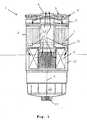
- FIG. 1 shows the principle of a preferred embodiment in a simplified representation in cross section.
- FIG. 1 schematically a fuel filter 1 is shown with a housing 2 , which is closed at its upper end with a cover 3. Der Deckel 3 ist mit Melckel 3sky. Overall, the fuel filter 1 is constructed substantially rotationally symmetrical about a central axis 4 and designed substantially pot-shaped.
- a fuel inlet 5 and in the middle of a fuel outlet 6 is provided.
- a first filter stage 7 is arranged, wherein extending between the lid 3 and the first filter stage 7, a radial distribution area 8 .
- the first filter stage 7 is arranged as a wound insert (wound filter) concentric to the central axis 4 .
- Cellulose and / or glass fibers which are partly or completely impregnated such that the filter material has coalescence properties and has a hydrophilic effect are preferably used as the filter material for the wound filter.
- the impregnated portion of the fibers is between about 60% and 90%.
- a second filter stage 9 is arranged, wherein between the first filter stage 7 and the second filter stage, a, in the manner of an annular disc extending, radial collecting area 11 is located. Between the second filter stage 9 formed by a star filter insert and the housing wall, there remains an annular gap which adjoins the radial collecting area 11 , axial distribution area 12 and encloses the second filter stage 9 radially from the outside.
- the outer area of the star filter insert is its dirty side, the inside the clean side, with the top and bottom of the star filter insert are sealed against the dirty side.
- the filter material for the second filter stage 9 various materials can be used. Preferably, at least in part, a material such as cellulose or synthetic fibers or glass fibers or the like is used more.
- the clean side of the second filter stage 9 is connected to the fuel outlet 6 in the cover 3 via an outlet pipe 13 extending along the center axis 4 .
- a water outlet 15 is provided, which can be closed by a drain screw, not shown here or a controllable discharge valve.
- the advantage of the arrangement of a radially infiltrated star filter insert behind an axially flowing winding insert is that the flow cross section of the winding insert is limited by the housing diameter and the outer diameter of the outlet tube 13 , the axial extent of the star filter insert but varies within certain limits depending on the height of the housing can be.
- the fuel to be filtered passes through the fuel inlet 5 via the radial distribution region 8 in the winding insert of the first filter stage 7.
- the first filter stage 7 is substantially axially, ie, flows parallel to its longitudinal axis and the central axis 4 . Due to the hydrophilic properties of the first filter stage, the water droplets distributed extremely finely in the emulsion are at least partially collected and combined to form larger water droplets and droplets.
- the fuel exits the first filter stage 7 into the radial collecting area 11 , from which it passes into the axial distribution area 12 .
- the axial distribution region 12 of the fuel to be filtered is distributed to the filter surface of the second filter stage 9 and occurs radially from outside to inside through the second filter stage 9 through, in the outlet pipe 17 and via the fuel outlet 6 from the housing 2 . Secluded water runs due to gravity on the dirty side of the second filter stage 9 in the sump 14 .
- the arrows 16 indicate the respective flow direction of the fuel in the housing.
- the invention can also be realized in other embodiments.
- a plurality of 3, 4, 5 or more filter stages may be provided.
- a hydrophilic filter stages is to be regarded as the first filter stage and another, downstream hydrophobic filter stage as the second.
- the "first" and “second” filter stages may be separated by one or more further filter stages.
- several filter cartridges can be combined to form a filter stage.
- the invention is not limited to the arrangement of a star filter insert as a second filter stage downstream of an axially flowed through wound filter as the first filter stage. Rather, suitable filter cartridges can be selected from a variety of known to the expert form of filter cartridges. The same applies to the selection of filter materials.
Landscapes
- Engineering & Computer Science (AREA)
- Chemical & Material Sciences (AREA)
- Chemical Kinetics & Catalysis (AREA)
- Combustion & Propulsion (AREA)
- Mechanical Engineering (AREA)
- General Engineering & Computer Science (AREA)
- Filtering Materials (AREA)
Claims (9)
- Filtre, en particulier filtre à carburant qui est construit essentiellement avec une symétrie de révolution autour d'un axe médian (4),
comprenant au moins un premier étage de filtre (7), qui se compose au moins en partie d'un matériau hydrophile, et au moins un deuxième étage de filtre (9) disposé en aval, qui se compose au moins en partie d'un matériau hydrophobe, caractérisé en ce que la section transversale d'écoulement du deuxième étage de filtre (9) est supérieure à la section transversale d'écoulement du premier étage de filtre (7),
le premier étage de filtre (7) étant traversé par l'écoulement essentiellement axialement,
le premier étage de filtre (7) comprenant un insert enroulé, en particulier le premier étage de filtre (7) se composant au moins en partie d'une combinaison des matériaux cellulose et fibres de verre,
la direction axiale s'étendant parallèlement à l'axe médian (4). - Filtre selon la revendication 1, caractérisé en ce que le deuxième étage de filtre (9) est disposé dans la direction axiale derrière le premier étage de filtre (7).
- Filtre selon l'une quelconque des revendications 1 ou 2, caractérisé en ce que le deuxième étage de filtre (9) est traversé par l'écoulement radialement et de préférence de l'extérieur vers l'intérieur.
- Filtre selon l'une quelconque des revendications 1 à 3, caractérisé en ce que le deuxième étage de filtre (9) est réalisé avec un milieu filtrant épais.
- Filtre selon l'une quelconque des revendications 1 à 4, caractérisé en ce que le degré de séparation d'eau du deuxième étage de filtre (9) est sensiblement indépendant d'une largeur de mailles de son tissu.
- Filtre selon l'une quelconque des revendications 1 à 5, caractérisé en ce que le matériau du deuxième étage de filtre (9) se compose au moins en partie de cellulose, de fibres synthétiques, de fibres de verre ou similaires, ou d'une combinaison de ces matériaux.
- Filtre selon l'une quelconque des revendications 1 à 6, caractérisé en ce que le deuxième étage de filtre (9) présente au moins une couche de matériau à microfibres, qui se compose de préférence au moins en partie de polyester.
- Filtre selon l'une quelconque des revendications 1 à 7, caractérisé en ce que le premier étage de filtre (7) se compose au moins en partie de cellulose ou de fibres de verre ou d'une combinaison de ces matériaux.
- Filtre (1) selon l'une quelconque des revendications 1 à 8, caractérisé en ce que le deuxième étage de filtre (9) comprend un insert de filtre en étoile.
Applications Claiming Priority (2)
| Application Number | Priority Date | Filing Date | Title |
|---|---|---|---|
| DE10360208 | 2003-12-20 | ||
| DE10360208A DE10360208A1 (de) | 2003-12-20 | 2003-12-20 | Zweistufiger Filter Kraftstofffilter |
Publications (4)
| Publication Number | Publication Date |
|---|---|
| EP1544452A2 EP1544452A2 (fr) | 2005-06-22 |
| EP1544452A3 EP1544452A3 (fr) | 2010-04-07 |
| EP1544452B1 EP1544452B1 (fr) | 2011-08-17 |
| EP1544452B2 true EP1544452B2 (fr) | 2018-02-21 |
Family
ID=34485561
Family Applications (1)
| Application Number | Title | Priority Date | Filing Date |
|---|---|---|---|
| EP04105333.1A Expired - Lifetime EP1544452B2 (fr) | 2003-12-20 | 2004-10-27 | Filtre à carburant à deux étages |
Country Status (3)
| Country | Link |
|---|---|
| EP (1) | EP1544452B2 (fr) |
| DE (1) | DE10360208A1 (fr) |
| ES (1) | ES2367990T3 (fr) |
Families Citing this family (7)
| Publication number | Priority date | Publication date | Assignee | Title |
|---|---|---|---|---|
| IT1400306B1 (it) * | 2010-05-25 | 2013-05-24 | Ufi Innovation Ct Srl | Gruppo filtrante perfezionato per motori endotermici. |
| ITRE20120089A1 (it) * | 2012-11-30 | 2014-05-31 | Ufi Filters Spa | Cartuccia filtrante |
| WO2014113430A1 (fr) * | 2013-01-15 | 2014-07-24 | Parker-Hannifin Corporation | Filtre à haute capacité et à plusieurs étages ainsi que système de milieu de coalescence en profondeur |
| DE102015218185A1 (de) * | 2015-09-22 | 2017-03-23 | Mahle International Gmbh | Filtermedium |
| WO2017110542A1 (fr) * | 2015-12-22 | 2017-06-29 | 京三電機株式会社 | Séparateur d'eau, filtre et dispositif de filtre à carburant |
| JP2017115858A (ja) * | 2015-12-22 | 2017-06-29 | 京三電機株式会社 | 水分離器、フィルタ、および燃料フィルタ装置 |
| DE102016010778A1 (de) | 2016-09-08 | 2018-03-08 | Mann+Hummel Gmbh | Trennmodul, Wasserabscheidevorrichtung mit einem Trennmodul und Filtersystem mit einer Wasserabscheidevorrichtung |
Citations (4)
| Publication number | Priority date | Publication date | Assignee | Title |
|---|---|---|---|---|
| US3465883A (en) † | 1967-07-25 | 1969-09-09 | Wix Corp | Fuel-water separator and filter |
| US4253954A (en) † | 1979-07-02 | 1981-03-03 | Nelson Industries, Inc. | Two-stage spin-on separating device |
| US5993675A (en) † | 1997-12-31 | 1999-11-30 | Hagerthy; Albert P. | Fuel-water separator for marine and diesel engines |
| WO2004082804A1 (fr) † | 2003-03-21 | 2004-09-30 | Mann+Hummel Gmbh | Systeme de filtre a carburant |
Family Cites Families (3)
| Publication number | Priority date | Publication date | Assignee | Title |
|---|---|---|---|---|
| US3187895A (en) * | 1963-01-23 | 1965-06-08 | Pall Corp | Fuel-water separator |
| US4372847A (en) * | 1980-06-23 | 1983-02-08 | Chicago Rawhide Manufacturing Company | Fuel filter assembly and cartridge |
| DE10123190A1 (de) * | 2001-05-12 | 2002-11-14 | Mahle Filtersysteme Gmbh | Kraftstofffilter mit wasserabscheidenden Mitteln |
-
2003
- 2003-12-20 DE DE10360208A patent/DE10360208A1/de not_active Ceased
-
2004
- 2004-10-27 ES ES04105333T patent/ES2367990T3/es not_active Expired - Lifetime
- 2004-10-27 EP EP04105333.1A patent/EP1544452B2/fr not_active Expired - Lifetime
Patent Citations (5)
| Publication number | Priority date | Publication date | Assignee | Title |
|---|---|---|---|---|
| US3465883A (en) † | 1967-07-25 | 1969-09-09 | Wix Corp | Fuel-water separator and filter |
| US4253954A (en) † | 1979-07-02 | 1981-03-03 | Nelson Industries, Inc. | Two-stage spin-on separating device |
| US5993675A (en) † | 1997-12-31 | 1999-11-30 | Hagerthy; Albert P. | Fuel-water separator for marine and diesel engines |
| WO2004082804A1 (fr) † | 2003-03-21 | 2004-09-30 | Mann+Hummel Gmbh | Systeme de filtre a carburant |
| EP1606037B1 (fr) † | 2003-03-21 | 2011-12-28 | MANN+HUMMEL GmbH | Systeme de filtre a carburant |
Non-Patent Citations (2)
| Title |
|---|
| Priodoc. DE 10313867 † |
| WENTE V.A. ET AL: "Manufacture of Superfine Organic Fibers", 10 April 1994, NAVAL RESEARCH LABORATORY, WASHINGTON D.C. † |
Also Published As
| Publication number | Publication date |
|---|---|
| EP1544452A2 (fr) | 2005-06-22 |
| EP1544452B1 (fr) | 2011-08-17 |
| DE10360208A1 (de) | 2005-07-28 |
| ES2367990T3 (es) | 2011-11-11 |
| EP1544452A3 (fr) | 2010-04-07 |
Similar Documents
| Publication | Publication Date | Title |
|---|---|---|
| EP2788099B1 (fr) | Filtre à carburant d'un moteur à combustion interne et élément filtrant d'un filtre à carburant | |
| EP2788612B1 (fr) | Filtre à carburant d'un moteur à combustion interne et élément filtrant d'un filtre à carburant | |
| DE102014000903B4 (de) | Filterelement und Filtervorrichtung | |
| DE102011120653A1 (de) | Kraftstofffilter einer Brennkraftmaschine und Filterelement eines Kraftstofffilters | |
| DE102010052329A1 (de) | Kraftstofffilter | |
| WO2004082804A1 (fr) | Systeme de filtre a carburant | |
| DE60003202T2 (de) | Verfahren und filter zur filtrierung eines schlammes | |
| WO2013079172A1 (fr) | Dispositif de filtration | |
| DE2126080B2 (de) | Rohrförmiges Trennelement zum Filtern und Abscheiden von Wasser und Feststoffen aus Kraftstoff | |
| DE102015003915A1 (de) | Abscheideelement einer Abscheidevorrichtung zur Abscheidung wenigstens eines fluiden Mediums aus einem zu behandelnden Fluid und Abscheidevorrichtung | |
| DE112017002974T5 (de) | Koaleszer mit perforierter schicht | |
| DE102012013743A1 (de) | Wasserabscheidevorrichtung, Filterelement eines Kraftstoff-Filters und Kraftstofffilter | |
| EP3423169B1 (fr) | Élément filtrant et filtre à carburant | |
| EP1544452B2 (fr) | Filtre à carburant à deux étages | |
| WO2015091011A1 (fr) | Milieu de filtrage et élément de filtrage présentant un milieu de filtrage | |
| DE102016009487A1 (de) | Abscheideelement, Vorrichtung sowie Verfahren zur Abscheidung von Flüssigkeit aus Rohgas oder aus Rohgasgemisch einer Kraftmaschine/Kompressors | |
| EP0878227A2 (fr) | Dispositif et élément pour séparer des liquides de courants de gaz | |
| WO2017137335A1 (fr) | Corps de milieu séparateur destiné à être utilisé dans un séparateur | |
| DE102012219885B3 (de) | Flüssigkeitsfilter | |
| EP3185983B1 (fr) | Moyen de filtrage terminal, utilisation et procédé de préparation | |
| DE69907726T2 (de) | Filterkartusche und verfahren zur filtration einer trübe | |
| WO2019072547A1 (fr) | Filtre à fluide | |
| DE10353367A1 (de) | System zur Abscheidung von Partikeln und Wasser | |
| DE102014006259B4 (de) | Koaleszenzelement eines Wasserabscheiders für Kraftstoff und Wasserabscheider | |
| EP3695893B1 (fr) | Dispositif filtrant |
Legal Events
| Date | Code | Title | Description |
|---|---|---|---|
| PUAI | Public reference made under article 153(3) epc to a published international application that has entered the european phase |
Free format text: ORIGINAL CODE: 0009012 |
|
| AK | Designated contracting states |
Kind code of ref document: A2 Designated state(s): AT BE BG CH CY CZ DE DK EE ES FI FR GB GR HU IE IT LI LU MC NL PL PT RO SE SI SK TR |
|
| AX | Request for extension of the european patent |
Extension state: AL HR LT LV MK |
|
| PUAL | Search report despatched |
Free format text: ORIGINAL CODE: 0009013 |
|
| AK | Designated contracting states |
Kind code of ref document: A3 Designated state(s): AT BE BG CH CY CZ DE DK EE ES FI FR GB GR HU IE IT LI LU MC NL PL PT RO SE SI SK TR |
|
| AX | Request for extension of the european patent |
Extension state: AL HR LT LV MK |
|
| 17P | Request for examination filed |
Effective date: 20101007 |
|
| AKX | Designation fees paid |
Designated state(s): DE ES FR IT |
|
| GRAP | Despatch of communication of intention to grant a patent |
Free format text: ORIGINAL CODE: EPIDOSNIGR1 |
|
| RIC1 | Information provided on ipc code assigned before grant |
Ipc: F02M 37/22 20060101AFI20110218BHEP |
|
| GRAS | Grant fee paid |
Free format text: ORIGINAL CODE: EPIDOSNIGR3 |
|
| GRAA | (expected) grant |
Free format text: ORIGINAL CODE: 0009210 |
|
| AK | Designated contracting states |
Kind code of ref document: B1 Designated state(s): DE ES FR IT |
|
| REG | Reference to a national code |
Ref country code: DE Ref legal event code: R096 Ref document number: 502004012796 Country of ref document: DE Effective date: 20111013 |
|
| REG | Reference to a national code |
Ref country code: ES Ref legal event code: FG2A Ref document number: 2367990 Country of ref document: ES Kind code of ref document: T3 Effective date: 20111111 |
|
| PLBI | Opposition filed |
Free format text: ORIGINAL CODE: 0009260 |
|
| PLAX | Notice of opposition and request to file observation + time limit sent |
Free format text: ORIGINAL CODE: EPIDOSNOBS2 |
|
| 26 | Opposition filed |
Opponent name: UFI FILTERS S.P.A. Effective date: 20120515 |
|
| REG | Reference to a national code |
Ref country code: DE Ref legal event code: R026 Ref document number: 502004012796 Country of ref document: DE Effective date: 20120515 |
|
| PLBB | Reply of patent proprietor to notice(s) of opposition received |
Free format text: ORIGINAL CODE: EPIDOSNOBS3 |
|
| PLAY | Examination report in opposition despatched + time limit |
Free format text: ORIGINAL CODE: EPIDOSNORE2 |
|
| PLAH | Information related to despatch of examination report in opposition + time limit modified |
Free format text: ORIGINAL CODE: EPIDOSCORE2 |
|
| REG | Reference to a national code |
Ref country code: FR Ref legal event code: PLFP Year of fee payment: 12 |
|
| PLBC | Reply to examination report in opposition received |
Free format text: ORIGINAL CODE: EPIDOSNORE3 |
|
| REG | Reference to a national code |
Ref country code: FR Ref legal event code: PLFP Year of fee payment: 13 |
|
| APAH | Appeal reference modified |
Free format text: ORIGINAL CODE: EPIDOSCREFNO |
|
| APBM | Appeal reference recorded |
Free format text: ORIGINAL CODE: EPIDOSNREFNO |
|
| APBP | Date of receipt of notice of appeal recorded |
Free format text: ORIGINAL CODE: EPIDOSNNOA2O |
|
| APBU | Appeal procedure closed |
Free format text: ORIGINAL CODE: EPIDOSNNOA9O |
|
| REG | Reference to a national code |
Ref country code: FR Ref legal event code: PLFP Year of fee payment: 14 |
|
| PUAH | Patent maintained in amended form |
Free format text: ORIGINAL CODE: 0009272 |
|
| STAA | Information on the status of an ep patent application or granted ep patent |
Free format text: STATUS: PATENT MAINTAINED AS AMENDED |
|
| 27A | Patent maintained in amended form |
Effective date: 20180221 |
|
| AK | Designated contracting states |
Kind code of ref document: B2 Designated state(s): DE ES FR IT |
|
| REG | Reference to a national code |
Ref country code: DE Ref legal event code: R102 Ref document number: 502004012796 Country of ref document: DE |
|
| PGFP | Annual fee paid to national office [announced via postgrant information from national office to epo] |
Ref country code: ES Payment date: 20171103 Year of fee payment: 14 |
|
| PG25 | Lapsed in a contracting state [announced via postgrant information from national office to epo] |
Ref country code: ES Free format text: LAPSE BECAUSE OF FAILURE TO SUBMIT A TRANSLATION OF THE DESCRIPTION OR TO PAY THE FEE WITHIN THE PRESCRIBED TIME-LIMIT Effective date: 20180221 |
|
| REG | Reference to a national code |
Ref country code: FR Ref legal event code: PLFP Year of fee payment: 15 |
|
| PGFP | Annual fee paid to national office [announced via postgrant information from national office to epo] |
Ref country code: FR Payment date: 20221020 Year of fee payment: 19 |
|
| PGFP | Annual fee paid to national office [announced via postgrant information from national office to epo] |
Ref country code: IT Payment date: 20221031 Year of fee payment: 19 Ref country code: DE Payment date: 20221215 Year of fee payment: 19 |
|
| REG | Reference to a national code |
Ref country code: DE Ref legal event code: R119 Ref document number: 502004012796 Country of ref document: DE |
|
| PG25 | Lapsed in a contracting state [announced via postgrant information from national office to epo] |
Ref country code: FR Free format text: LAPSE BECAUSE OF NON-PAYMENT OF DUE FEES Effective date: 20231031 Ref country code: DE Free format text: LAPSE BECAUSE OF NON-PAYMENT OF DUE FEES Effective date: 20240501 |
|
| PG25 | Lapsed in a contracting state [announced via postgrant information from national office to epo] |
Ref country code: IT Free format text: LAPSE BECAUSE OF NON-PAYMENT OF DUE FEES Effective date: 20231027 |
|
| PG25 | Lapsed in a contracting state [announced via postgrant information from national office to epo] |
Ref country code: IT Free format text: LAPSE BECAUSE OF NON-PAYMENT OF DUE FEES Effective date: 20231027 |