EP1544452A2 - Two-stage fuel filter - Google Patents
Two-stage fuel filter Download PDFInfo
- Publication number
- EP1544452A2 EP1544452A2 EP04105333A EP04105333A EP1544452A2 EP 1544452 A2 EP1544452 A2 EP 1544452A2 EP 04105333 A EP04105333 A EP 04105333A EP 04105333 A EP04105333 A EP 04105333A EP 1544452 A2 EP1544452 A2 EP 1544452A2
- Authority
- EP
- European Patent Office
- Prior art keywords
- filter
- filter stage
- stage
- fuel
- insert
- Prior art date
- Legal status (The legal status is an assumption and is not a legal conclusion. Google has not performed a legal analysis and makes no representation as to the accuracy of the status listed.)
- Granted
Links
Images
Classifications
-
- B—PERFORMING OPERATIONS; TRANSPORTING
- B01—PHYSICAL OR CHEMICAL PROCESSES OR APPARATUS IN GENERAL
- B01D—SEPARATION
- B01D36/00—Filter circuits or combinations of filters with other separating devices
- B01D36/003—Filters in combination with devices for the removal of liquids
-
- B—PERFORMING OPERATIONS; TRANSPORTING
- B01—PHYSICAL OR CHEMICAL PROCESSES OR APPARATUS IN GENERAL
- B01D—SEPARATION
- B01D27/00—Cartridge filters of the throw-away type
- B01D27/04—Cartridge filters of the throw-away type with cartridges made of a piece of unitary material, e.g. filter paper
- B01D27/06—Cartridge filters of the throw-away type with cartridges made of a piece of unitary material, e.g. filter paper with corrugated, folded or wound material
- B01D27/07—Cartridge filters of the throw-away type with cartridges made of a piece of unitary material, e.g. filter paper with corrugated, folded or wound material having a coaxial stream through the filtering element
-
- B—PERFORMING OPERATIONS; TRANSPORTING
- B01—PHYSICAL OR CHEMICAL PROCESSES OR APPARATUS IN GENERAL
- B01D—SEPARATION
- B01D27/00—Cartridge filters of the throw-away type
- B01D27/14—Cartridge filters of the throw-away type having more than one filtering element
- B01D27/146—Cartridge filters of the throw-away type having more than one filtering element connected in series
- B01D27/148—Cartridge filters of the throw-away type having more than one filtering element connected in series arranged concentrically or coaxially
-
- F—MECHANICAL ENGINEERING; LIGHTING; HEATING; WEAPONS; BLASTING
- F02—COMBUSTION ENGINES; HOT-GAS OR COMBUSTION-PRODUCT ENGINE PLANTS
- F02M—SUPPLYING COMBUSTION ENGINES IN GENERAL WITH COMBUSTIBLE MIXTURES OR CONSTITUENTS THEREOF
- F02M37/00—Apparatus or systems for feeding liquid fuel from storage containers to carburettors or fuel-injection apparatus; Arrangements for purifying liquid fuel specially adapted for, or arranged on, internal-combustion engines
- F02M37/22—Arrangements for purifying liquid fuel specially adapted for, or arranged on, internal-combustion engines, e.g. arrangements in the feeding system
- F02M37/24—Arrangements for purifying liquid fuel specially adapted for, or arranged on, internal-combustion engines, e.g. arrangements in the feeding system characterised by water separating means
-
- F—MECHANICAL ENGINEERING; LIGHTING; HEATING; WEAPONS; BLASTING
- F02—COMBUSTION ENGINES; HOT-GAS OR COMBUSTION-PRODUCT ENGINE PLANTS
- F02M—SUPPLYING COMBUSTION ENGINES IN GENERAL WITH COMBUSTIBLE MIXTURES OR CONSTITUENTS THEREOF
- F02M37/00—Apparatus or systems for feeding liquid fuel from storage containers to carburettors or fuel-injection apparatus; Arrangements for purifying liquid fuel specially adapted for, or arranged on, internal-combustion engines
- F02M37/22—Arrangements for purifying liquid fuel specially adapted for, or arranged on, internal-combustion engines, e.g. arrangements in the feeding system
- F02M37/32—Arrangements for purifying liquid fuel specially adapted for, or arranged on, internal-combustion engines, e.g. arrangements in the feeding system characterised by filters or filter arrangements
- F02M37/34—Arrangements for purifying liquid fuel specially adapted for, or arranged on, internal-combustion engines, e.g. arrangements in the feeding system characterised by filters or filter arrangements by the filter structure, e.g. honeycomb, mesh or fibrous
Definitions
- the invention relates to a two-stage filter, in particular a fuel filter, with at least a first filter stage, at least partially made of a hydrophilic material, and at least one downstream second filter stage, at least partially made of a hydrophobic material consists.
- Fuel filters are used in diesel engines, among others Filtering out impurities contained in diesel fuel and for separating water from the diesel fuel used to disturb and damage caused thereby For example, contamination or corrosion in the fuel system or to avoid a worse combustion in the engine.
- 190 A1 is a fuel filter of the beginning known type.
- the fuel filter has a housing a cylindrical filter element receiving cup-shaped Lower part on.
- the filter insert is replaced by a formed two-stage filter, wherein a first filter stage with a hydrophilic filter material from a second filter stage downstream of a hydrophobic filter material at a small distance is. Both filter stages are concentric with each other and directly arranged one another or at a small distance from each other and are flowed through radially from outside to inside.
- the first filter stage lets through the hydrophilic properties in the fuel contained, finely divided water to droplets or drops coalesce, which then at the hydrophobic second filter stage collected and separated by gravity.
- a filter for diesel fuels with a first and a second filter stage known to be concentric with each other within a filter housing are arranged. While the first filter stage as a winding insert is formed, the second filter stage in the art arranged an inverted basket within the winding insert.
- the fuel to be filtered enters axially from top to bottom through the first filter stage and passes over a room below the filter stages from the bottom to the second filter stage one. While in the first filter stage particles from the fuel be filtered out, at the second, as a tissue trained filter stage deposited water.
- This object is achieved in a filter of the type mentioned achieved in that the flow cross-section of the second filter stage larger than the flow cross section of the first filter stage is.
- An essential core idea of the invention is that unlike the fuel filter known from DE 101 23 190 A1 - Due to one compared to the first filter stage larger Flow cross section of the second filter stage, the flow rate in the second filter stage compared to the Flow rate reduced in the first filter stage is. This will cause the collection of droplets and drops that are have formed in the hydrophilic first filter stage, as well as their Joining to larger drops supports, so the water separation efficiency is significantly increased.
- the filter according to the invention provides the essential Advantage that compared to conventional filters the degree of separation for water contained in the fuel improved or at compared to conventional filters the same degree of separation, the area of the filter material can be reduced overall.
- the filter stages are concentric with each other to arrange, with the first filter stage at the same height of Filter stages is the interior of the two filter stages, and where the filter stages are traversed radially from the inside to the outside.
- the second filter stage is preferred in the axial direction or in the direction of an axis of symmetry of the filter substantially arranged behind the first filter stage. That is insofar advantageous than the flow cross sections of the filter stages are more freely selectable than when arranged radially to each other Filter stages.
- the first Filter stage flows substantially axially.
- the second filter stage is radial and special is preferably flowed through from the outside to the inside. The installation of the Filter is then preferably such that the axial direction essentially the vertical direction and the radial direction corresponds to the horizontal direction, so that deposited Water in the second filter stage transverse to the flow direction to Bottom of the filter housing can sink.
- the second filter stage at least one thick filter medium.
- the advantage of a comparatively thick filter medium is that so in the second filter stage not only water deposited, but Also particles from the fuel can be filtered out. Since the fuel then through both the first filter stage, as also filtered by the second filter stage, the life can of the filter can be increased significantly.
- the second filter stage is such that the passage of water droplets or water droplets completely is prevented.
- the structure of the filter therefore such that the separation efficiency of Water of the second filter stage substantially independent of a mesh size of a fabric.
- the filter material of the second filter stage is preferably cellulose, synthetic fibers, glass fibers or the like or a combination of these materials. It is preferred for the second filter stage a filter material with extremely fine Pores used to achieve a high degree of separation. Of the Abscheidegrad then depends on the pore size of the filter material and not on the mesh size of a fabric, and it can even very small water droplets are deposited so that the Abscheidegrad is very high.
- the second filter stage preferably not a thin, membranous, but a thick one Filter layer, with the dirt or other particles from can be filtered out of the fuel. It can the Thickness of the layer, the service life and also the degree of separation influence. Preferred is a filter thickness of about 0.5 mm or more, but there are also smaller thicknesses possible.
- the hydrophobic effect of the second filter stage can, for example be achieved by materials in the filter stage such as. Polyester, silicone, PTFE (Teflon), wax, polypropylene or fluorinated acrylates, fluorinated resoles or comparable contained in the prior art known materials are included. Also, the use of an example of polyester existing microfiber material, in particular a microfiber web (Melt-Blown), or the use of a microporous Barrier layer is possible.
- the second filter stage is a star filter cartridge educated.
- flow cross-section of a star filter insert Here, the mean flow cross-section is understood, which is from the middle radius of the star filter folded Filter material results.
- the first filter stage can at least partially consist of a Material such as Cellulose or glass fibers exist.
- the first filter stage comprises a winding insert.
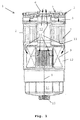
- Figure 1 shows the principle of a preferred embodiment in a simplified representation in cross section.
- the fuel filter 1 shows schematically a fuel filter 1 with a housing 2 , which is closed at its upper end with a cover 3 .
- the fuel filter 1 is constructed substantially rotationally symmetrical about a central axis 4 and designed substantially pot-shaped.
- a fuel inlet 5 and in the middle of a fuel outlet 6 is provided.
- a first filter stage 7 is arranged, wherein extending between the lid 3 and the first filter stage 7, a radial distribution area 8 .
- the first filter stage 7 is arranged as a wound insert (wound filter) concentric to the central axis 4 .
- Cellulose and / or glass fibers which are partly or completely impregnated such that the filter material has coalescence properties and has a hydrophilic effect are preferably used as the filter material for the wound filter.
- the impregnated portion of the fibers is between about 60% and 90%.
- a second filter stage 9 is arranged, wherein between the first filter stage 7 and the second filter stage, a, in the manner of an annular disc extending, radial collecting area 11 is located. Between the second filter stage 9 formed by a star filter insert and the housing wall, there remains an annular gap which adjoins the radial collecting area 11 , axial distribution area 12 and encloses the second filter stage 9 radially from the outside.
- the outer area of the star filter insert is its dirty side, the inside the clean side, with the top and bottom of the star filter insert are sealed against the dirty side.
- the filter material for the second filter stage 9 various materials can be used. Preferably, at least in part, a material such as cellulose or synthetic fibers or glass fibers or the like is used more.
- the clean side of the second filter stage 9 is connected to the fuel outlet 6 in the cover 3 via an outlet pipe 13 extending along the center axis 4 .
- a water outlet 15 is provided, which can be closed by a drain screw, not shown here or a controllable discharge valve.
- the advantage of the arrangement of a radially infiltrated star filter insert behind an axially flowing winding insert is that the flow cross section of the winding insert is limited by the housing diameter and the outer diameter of the outlet tube 13 , the axial extent of the star filter insert but varies within certain limits depending on the height of the housing can be.
- the fuel to be filtered passes through the fuel inlet 5 via the radial distribution region 8 in the winding insert of the first filter stage 7.
- the first filter stage 7 is substantially axially, ie, flows parallel to its longitudinal axis and the central axis 4 . Due to the hydrophilic properties of the first filter stage, the water droplets distributed extremely finely in the emulsion are at least partially collected and combined to form larger water droplets and droplets.
- the fuel exits the first filter stage 7 into the radial collecting area 11 , from which it passes into the axial distribution area 12 .
- the axial distribution region 12 of the fuel to be filtered is distributed to the filter surface of the second filter stage 9 and occurs radially from outside to inside through the second filter stage 9 through, in the outlet pipe 17 and via the fuel outlet 6 from the housing 2 . Secluded water runs due to gravity on the dirty side of the second filter stage 9 in the sump 14 .
- the arrows 16 indicate the respective flow direction of the fuel in the housing.
- the Invention can also be realized in other embodiments.
- a plurality of 3, 4, 5 or more filter stages be provided.
- a hydrophilic filter stages as view first filter stage and another, downstream located hydrophobic filter stage as the second.
- the "first" and the "second” filter level can be one or more more Filter stages be separated.
- several filter cartridges can too be summarized a filter stage.
- the invention not on the arrangement of a star filter insert as the second Filter stage downstream behind an axially traversed Wickelfilter limited as the first filter stage. Rather, you can suitable filter inserts from a variety of the expert known form of filter cartridges are selected. The same applies to the selection of filter materials.
Abstract
Description
Die Erfindung betrifft einen zweistufigen Filter, insbesondere einen Kraftstofffilter, mit mindestens einer ersten Filterstufe, die wenigstens teilweise aus einem hydrophilen Material besteht, und mindestens einer stromabwärts angeordneten zweiten Filterstufe, die wenigstens teilweise aus einem hydrophoben Material besteht.The invention relates to a two-stage filter, in particular a fuel filter, with at least a first filter stage, at least partially made of a hydrophilic material, and at least one downstream second filter stage, at least partially made of a hydrophobic material consists.
Kraftstofffilter werden unter anderem in Dieselmotoren zum Herausfiltern von in Dieselkraftstoff enthaltenen Verunreinigungen und zum Abscheiden von Wasser aus dem Dieselkraftstoff eingesetzt, um hierdurch verursachte Störungen und Schäden wie beispielsweise Verunreinigungen oder Korrosion im Kraftstoffsystem oder eine schlechtere Verbrennung im Motor zu vermeiden.Fuel filters are used in diesel engines, among others Filtering out impurities contained in diesel fuel and for separating water from the diesel fuel used to disturb and damage caused thereby For example, contamination or corrosion in the fuel system or to avoid a worse combustion in the engine.
Aus der DE 101 23 190 A1 ist ein Kraftstofffilter der eingangs genannten Art bekannt. Der Kraftstofffilter weist ein Gehäuse mit einem einen zylindrischen Filtereinsatz aufnehmenden becherförmigen Unterteil auf. Der Filtereinsatz wird durch einen zweistufigen Filter gebildet, wobei einer ersten Filterstufe mit einem hydrophilen Filtermaterial eine zweite Filterstufe aus einem hydrophobem Filtermaterial in geringem Abstand nachgeordnet ist. Beide Filterstufen sind konzentrisch zueinander und direkt aneinander oder in geringem Abstand zueinander angeordnet und werden radial von außen nach innen durchströmt. Die erste Filterstufe lässt durch die hydrophilen Eigenschaften im Kraftstoff enthaltenes, fein verteiltes Wasser zu Tröpfchen oder Tropfen koaleszieren, welche dann an der hydrophoben zweiten Filterstufe gesammelt und über die Schwerkraft abgeschieden werden. From DE 101 23 190 A1 is a fuel filter of the beginning known type. The fuel filter has a housing a cylindrical filter element receiving cup-shaped Lower part on. The filter insert is replaced by a formed two-stage filter, wherein a first filter stage with a hydrophilic filter material from a second filter stage downstream of a hydrophobic filter material at a small distance is. Both filter stages are concentric with each other and directly arranged one another or at a small distance from each other and are flowed through radially from outside to inside. The first filter stage lets through the hydrophilic properties in the fuel contained, finely divided water to droplets or drops coalesce, which then at the hydrophobic second filter stage collected and separated by gravity.
Des weiteren ist aus der EP 1 267 068 A2 ein Filter für Dieselkraftstoffe
mit einer ersten und einer zweiten Filterstufe
bekannt, die innerhalb eines Filtergehäuses zueinander konzentrisch
angeordnet sind. Während die erste Filterstufe als Wickeleinsatz
ausgebildet ist, ist die zweite Filterstufe in der Art
eines umgedrehten Korbes innerhalb des Wickeleinsatzes angeordnet.
Der zu filternde Kraftstoff tritt axial von oben nach unten
durch die erste Filterstufe hindurch und gelangt über einen Raum
unterhalb der Filterstufen von unten in die zweite Filterstufe
ein. Während in der ersten Filterstufe Partikel aus dem Kraftstoff
herausgefiltert werden, wird an der zweiten, als Gewebe
ausgebildeten Filterstufe Wasser abgeschieden.Furthermore, from
Es ist die Aufgabe der vorliegenden Erfindung, einen Filter zur Verfügung zu stellen, der eine verbesserte Abscheidung von Wasser ermöglicht.It is the object of the present invention to provide a filter for To provide an improved separation of water allows.
Diese Aufgabe wird bei einem Filter der eingangs genannten Art dadurch gelöst, dass der Strömungsquerschnitt der zweiten Filterstufe größer als der Strömungsquerschnitt der ersten Filterstufe ist.This object is achieved in a filter of the type mentioned achieved in that the flow cross-section of the second filter stage larger than the flow cross section of the first filter stage is.
Wie bei dem aus der DE 101 23 190 A1 bekannten Kraftstofffilter besteht auch beim erfindungsgemäßen Kraftstofffilter das Prinzip des Wasserabscheidens darin, dass das im Kraftstoff enthaltene Wasser in der ersten Filterstufe aufgrund ihrer hydrophilen Eigenschaften koalesziert, so dass sich kleine Tröpfchen oder Tropfen bilden, die in der zweiten Filterstufe gesammelt und abgeschieden werden.As in the fuel filter known from DE 101 23 190 A1 There is also the principle of the fuel filter according to the invention of water separation in that contained in the fuel Water in the first filter stage due to its hydrophilic Coalesced properties, allowing small droplets or Drops collected in the second filter stage and be deposited.
Ein wesentlicher Kerngedanke der Erfindung besteht darin, dass - anders als bei dem aus der DE 101 23 190 A1 bekannten Kraftstofffilter - aufgrund einem gegenüber der ersten Filterstufe größeren Strömungsquerschnitt der zweiten Filterstufe die Strömungsgeschwindigkeit in der zweiten Filterstufe gegenüber der Strömungsgeschwindigkeit in der ersten Filterstufe herabgesetzt ist. Dadurch wird das Sammeln von Tröpfchen und Tropfen, die sich in der hydrophilen ersten Filterstufe gebildet haben, sowie deren Verbinden zu größeren Tropfen unterstützt, so dass der Wasserabscheidegrad wesentlich erhöht wird. An essential core idea of the invention is that unlike the fuel filter known from DE 101 23 190 A1 - Due to one compared to the first filter stage larger Flow cross section of the second filter stage, the flow rate in the second filter stage compared to the Flow rate reduced in the first filter stage is. This will cause the collection of droplets and drops that are have formed in the hydrophilic first filter stage, as well as their Joining to larger drops supports, so the water separation efficiency is significantly increased.
Im Ergebnis bietet der erfindungsgemäße Filter den wesentlichen Vorteil, dass gegenüber herkömmlichen Filtern der Abscheidegrad für im Kraftstoff enthaltenes Wasser verbessert oder bei gegenüber herkömmlichen Filtern gleichem Abscheidegrad die Fläche des Filtermaterials insgesamt verringert werden kann.As a result, the filter according to the invention provides the essential Advantage that compared to conventional filters the degree of separation for water contained in the fuel improved or at compared to conventional filters the same degree of separation, the area of the filter material can be reduced overall.
In einer einfachen Ausgestaltung der Erfindung ist es beispielsweise möglich, die Filterstufen konzentrisch zueinander anzuordnen, wobei die erste Filterstufe bei gleicher Höhe der Filterstufen die innere der beiden Filterstufen ist, und wobei die Filterstufen radial von innen nach außen durchflossen werden. Bevorzugt wird die zweite Filterstufe jedoch in axialer Richtung bzw. in Richtung einer Symmetrieachse des Filters im Wesentlichen hinter der ersten Filterstufe angeordnet. Das ist insofern vorteilhaft, als die Strömungsquerschnitte der Filterstufen freier wählbar sind als bei radial zueinander angeordneten Filterstufen.In a simple embodiment of the invention it is For example, the filter stages are concentric with each other to arrange, with the first filter stage at the same height of Filter stages is the interior of the two filter stages, and where the filter stages are traversed radially from the inside to the outside. However, the second filter stage is preferred in the axial direction or in the direction of an axis of symmetry of the filter substantially arranged behind the first filter stage. That is insofar advantageous than the flow cross sections of the filter stages are more freely selectable than when arranged radially to each other Filter stages.
In einer darüber hinaus bevorzugten Weiterbildung wird die erste Filterstufe im Wesentlichen axial durchströmt. Bevorzugt ist weiterhin, dass die zweite Filterstufe radial und besonders bevorzugt von außen nach innen durchströmt wird. Der Einbau des Filters erfolgt dann bevorzugt derart, dass die axiale Richtung im Wesentlichen der vertikalen Richtung und die radiale Richtung der horizontalen Richtung entspricht, so dass abgeschiedenes Wasser in der zweiten Filterstufe quer zur Strömungsrichtung zum Boden des Filtergehäuses absinken kann.In a further preferred development, the first Filter stage flows substantially axially. Is preferred Furthermore, the second filter stage is radial and special is preferably flowed through from the outside to the inside. The installation of the Filter is then preferably such that the axial direction essentially the vertical direction and the radial direction corresponds to the horizontal direction, so that deposited Water in the second filter stage transverse to the flow direction to Bottom of the filter housing can sink.
In einer bevorzugten Weiterbildung weist die zweite Filterstufe wenigstens ein dickes Filtermedium auf. Der Vorteil eines vergleichsweise dicken Filtermediums besteht darin, dass damit in der zweiten Filterstufe nicht nur Wasser abgeschieden, sondern auch Partikel aus dem Kraftstoff herausgefiltert werden können. Da der Kraftstoff dann sowohl durch die erste Filterstufe, als auch durch die zweite Filterstufe gefiltert wird, kann die Standzeit des Filters erheblich erhöht werden. Vorzugsweise wird ein filtermaterial in der Dicke von wenigstens 0,5 mm verwendet. Möglich sind aber auch dünnere Schichten, wie z.B. 0,4 mm. In a preferred embodiment, the second filter stage at least one thick filter medium. The advantage of a comparatively thick filter medium is that so in the second filter stage not only water deposited, but Also particles from the fuel can be filtered out. Since the fuel then through both the first filter stage, as also filtered by the second filter stage, the life can of the filter can be increased significantly. Preferably, a used in the thickness of at least 0.5 mm. But are also possible thinner layers, such. 0.4 mm.
Vorzugsweise ist die zweite Filterstufe derart beschaffen, dass das Hindurchtreten von Wassertropfen oder Wassertröpfchen vollständig unterbunden wird. In einer bevorzugten Ausgestaltung ist der Aufbau des Filters daher derart, dass der Abscheidegrad von Wasser der zweiten Filterstufe im Wesentlichen unabhängig von einer Maschenweite eines Gewebes ist.Preferably, the second filter stage is such that the passage of water droplets or water droplets completely is prevented. In a preferred embodiment the structure of the filter therefore such that the separation efficiency of Water of the second filter stage substantially independent of a mesh size of a fabric.
Das Filtermaterial der zweiten Filterstufe besteht vorzugsweise aus Zellulose, synthetischen Fasern, Glasfasern oder dergleichen oder aus einer Kombination dieser Materialien. Bevorzugt wird für die zweite Filterstufe ein Filtermaterial mit äußerst feinen Poren eingesetzt, um einen hohen Abscheidegrad zu erzielen. Der Abscheidegrad hängt dann von der Porengröße des Filtermaterials und nicht von der Maschenweite eines Gewebes ab, und es können auch sehr kleine Wassertröpfchen abgeschieden werden, so dass der Abscheidegrad sehr hoch ist. Dabei ist die zweite Filterstufe vorzugsweise keine dünne, membranartige, sondern eine dicke Filterschicht, mit der auch Schmutz- oder sonstige Partikel aus dem Kraftstoff herausgefiltert werden können. Dabei kann die Dicke der Schicht die Standzeit und auch den Abscheidegrad beeinflussen. Bevorzugt ist eine Filterdicke von ca. 0,5 mm oder mehr, es sind aber auch kleinere Dicken möglich.The filter material of the second filter stage is preferably cellulose, synthetic fibers, glass fibers or the like or a combination of these materials. It is preferred for the second filter stage a filter material with extremely fine Pores used to achieve a high degree of separation. Of the Abscheidegrad then depends on the pore size of the filter material and not on the mesh size of a fabric, and it can even very small water droplets are deposited so that the Abscheidegrad is very high. Here is the second filter stage preferably not a thin, membranous, but a thick one Filter layer, with the dirt or other particles from can be filtered out of the fuel. It can the Thickness of the layer, the service life and also the degree of separation influence. Preferred is a filter thickness of about 0.5 mm or more, but there are also smaller thicknesses possible.
Die hydrophobe Wirkung der zweiten Filterstufe kann beispielsweise dadurch erzielt werden, dass in der Filterstufe Materialien wie z.B. Polyester, Silikon, PTFE (Teflon), Wachs, Polypropylen oder fluorisierte Acrylate, fluorisierte Resole oder vergleichbare im Stand der Technik bekannte Materialien enthalten sind. Auch der Einsatz von einem beispielsweise aus Polyester bestehenden Mikrofaser-Material, insbesondere einem Mikrofaservlies (Melt-Blown), oder die Verwendung einer mikroporösen Sperrschicht ist möglich.The hydrophobic effect of the second filter stage can, for example be achieved by materials in the filter stage such as. Polyester, silicone, PTFE (Teflon), wax, polypropylene or fluorinated acrylates, fluorinated resoles or comparable contained in the prior art known materials are included. Also, the use of an example of polyester existing microfiber material, in particular a microfiber web (Melt-Blown), or the use of a microporous Barrier layer is possible.
Vorzugsweise ist die zweite Filterstufe als Sternfiltereinsatz ausgebildet. Als Strömungsquerschnitt eines Sternfiltereinsatzes wird hier der mittlere Strömungsquerschnitt verstanden, der sich aus dem mittleren Radius des als Sternfilter gefalteten Filtermaterials ergibt. Preferably, the second filter stage is a star filter cartridge educated. As flow cross-section of a star filter insert Here, the mean flow cross-section is understood, which is from the middle radius of the star filter folded Filter material results.
Die erste Filterstufe kann wenigstens teilweise aus einem Material wie z.B. Zellulose oder Glasfasern bestehen.The first filter stage can at least partially consist of a Material such as Cellulose or glass fibers exist.
Vorzugsweise umfasst die erste Filterstufe einen Wickeleinsatz.Preferably, the first filter stage comprises a winding insert.
Weitere Vorteile und Anwendungsmöglichkeiten der vorliegenden Erfindung ergeben sich aus dem Ausführungsbeispiel, das im folgenden mit Bezug auf die Figur beschrieben wird.Further advantages and applications of the present Invention will be apparent from the embodiment, which is in The following will be described with reference to the figure.
Figur 1 zeigt das Prinzip eines bevorzugten Ausführungsbeispiels in vereinfachter Darstellung im Querschnitt.Figure 1 shows the principle of a preferred embodiment in a simplified representation in cross section.
In Figur 1 ist schematisch ein Kraftstofffilter 1 mit einem
Gehäuse 2 dargestellt, das an seinem oberen Ende mit einem Deckel
3 verschlossen ist. Insgesamt ist der Kraftstofffilter 1 im
Wesentlichen rotationssymmetrisch um eine Mittelachse 4 aufgebaut
und im Wesentlichen topfförmig gestaltet.1 shows schematically a
In einem radial äußeren Bereich ist im Deckel 3 ein Kraftstoffeinlass
5 und in dessen Mitte ein Kraftstoffauslass 6 vorgesehen.
Unterhalb des Deckels 3 ist eine erste Filterstufe 7 angeordnet,
wobei sich zwischen Deckel 3 und erster Filterstufe 7 ein
radialer Verteilungsbereich 8 erstreckt.In a radially outer region in the
Die erste Filterstufe 7 ist als gewickelter Einsatz (Wickelfilter)
konzentrisch zur Mittelachse 4 angeordnet. Als Filtermaterial
für den Wickelfilter werden bevorzugt Zellulose-
und/oder Glasfasern verwendet, welche teilweise oder ganz so
imprägniert sind, dass das Filtermaterial Koaleszenzeigenschaften
hat und hydrophil wirkt. Vorzugsweise beträgt der imprägnierte
Anteil der Fasern zwischen etwa 60% und 90%.The
Unterhalb der ersten Filterstufe 7 ist eine zweite Filterstufe 9
angeordnet, wobei sich zwischen der ersten Filterstufe 7 und der
zweiten Filterstufe ein sich in der Art einer Ringscheibe
erstreckender, radialer Sammelbereich 11 befindet. Zwischen der
durch einen Sternfiltereinsatz gebildeten zweiten Filterstufe 9
und der Gehäusewand verbleibt ein sich an den radialen
Sammelbereich 11 anschließender, axialer Verteilungsbereich 12
wirkender Ringspalt, der die zweite Filterstufe 9 radial von
außen umschließt. Der Außenbereich des Sternfiltereinsatzes ist
seine Schmutzseite, die Innenseite die Reinseite, wobei die Ober-
und Unterseite des Sternfiltereinsatzes gegenüber der
Schmutzseite abgedichtet sind. Als Filtermaterial für die zweite
Filterstufe 9 können verschiedene Materialien verwendet werden.
Vorzugsweise wird wenigstens zum Teil ein Material wie Zellulose
oder es werden synthetische Fasern oder Glasfasern oder
dergleichen mehr eingesetzt.Below the
Die Reinseite der zweiten Filterstufe 9 ist über ein sich entlang
der Mittelachse 4 erstreckendes Auslassrohr 13 mit dem Kraftstoffauslass
6 im Deckel 3 verbunden.The clean side of the second filter stage 9 is connected to the
Unterhalb der zweiten Filterstufe 9 erstreckt sich der Bodenbereich
des Gehäuses 2, der als Sumpf 14 für abgeschiedenes
Wasser dient. Am Boden des Sumpfs 14 ist ein Wasserablass 15
vorgesehen, der über eine hier nicht dargestellte Ablassschraube
oder ein steuerbares Ablassventil verschließbar ist.Below the second filter stage 9 extends the bottom portion of the
Der Vorteil der Anordnung eines radial durchflossenen Sternfiltereinsatzes
hinter einem axial durchflossenen Wickeleinsatz
besteht darin, dass der Strömungsquerschnitt des Wickeleinsatzes
durch den Gehäusedurchmesser und den Außendurchmesser des
Auslassrohres 13 beschränkt ist, die axiale Ausdehnung des
Sternfiltereinsatzes aber in bestimmten Grenzen in Abhängigkeit
von der Höhe des Gehäuses variiert werden kann. Somit kann über
die Wahl einer geeigneten Höhe des Sternfiltereinsatzes dafür
Sorge getragen werden, dass sein mittlerer Strömungsquerschnitt
größer als der Strömungsquerschnitt des Wickeleinsatzes und die
mittlere Strömungsgeschwindigkeit innerhalb des Sternfiltereinsatzes
dementsprechend geringer als die Strömungsgeschwindigkeit
im Wickeleinsatz ist.The advantage of the arrangement of a radially infiltrated star filter insert behind an axially flowing winding insert is that the flow cross section of the winding insert is limited by the housing diameter and the outer diameter of the
Der zu filternde Kraftstoff gelangt durch den Kraftstoffeinlass 5
über den radialen Verteilungsbereich 8 in den Wickeleinsatz der
ersten Filterstufe 7. Die erste Filterstufe 7 wird im
Wesentlichen axial, also parallel zu seiner Längsachse und zur
Mittelachse 4 durchströmt. Dabei werden bedingt durch die
hydrophilen Eigenschaften der ersten Filterstufe die in der
Emulsion extrem fein verteilten Wassertröpfchen wenigstens
teilweise gesammelt und zu größeren Wassertröpfchen und -tropfen
vereinigt. Der Kraftstoff tritt aus der ersten Filterstufe 7
in den radialen Sammelbereich 11 aus, von dem aus er in den
axialen Verteilungsbereich 12 gelangt.The fuel to be filtered passes through the
Im axialen Verteilungsbereich 12 wird der zu filternde Kraftstoff
auf die Filterfläche der zweiten Filterstufe 9 verteilt und tritt
radial von außen nach innen durch die zweite Filterstufe 9
hindurch, in das Auslassrohr 17 ein und über den Kraftstoffauslass
6 aus dem Gehäuse 2 aus. Abgeschiedenes Wasser läuft
schwerkraftbedingt an der Schmutzseite der zweiten Filterstufe 9
in den Sumpf 14 ab.In the
Die Pfeile 16 zeigen die jeweilige Strömungsrichtung des
Kraftstoffs im Gehäuse an.The
Neben der konkret beschriebenen Ausführungsform kann die Erfindung auch in anderen Ausgestaltungen realisiert werden. Beispielsweise kann eine Vielzahl von 3, 4, 5 oder mehr Filterstufen vorgesehen sein. Dann ist eine hydrophile Filterstufen als erste Filterstufe anzusehen und eine weitere, stromabwärts gelegene hydrophobe Filterstufe als zweite. Die "erste" und die "zweite" Filterstufe können durch eine oder auch mehrere weitere Filterstufen getrennt sein. Auch können mehrere Filtereinsätze zu einer Filterstufe zusammengefasst sein. Auch ist die Erfindung nicht auf die Anordnung eines Sternfiltereinsatzes als zweite Filterstufe stromabwärts hinter einem axial durchflossenen Wickelfilter als erster Filterstufe beschränkt. Vielmehr können geeignete Filtereinsätze aus einer Vielzahl dem Fachmann bekannten Form von Filtereinsätzen gewählt werden. Entsprechendes gilt für die Auswahl der Filtermaterialien.In addition to the specific embodiment described, the Invention can also be realized in other embodiments. For example, a plurality of 3, 4, 5 or more filter stages be provided. Then a hydrophilic filter stages as view first filter stage and another, downstream located hydrophobic filter stage as the second. The "first" and the "second" filter level can be one or more more Filter stages be separated. Also, several filter cartridges can too be summarized a filter stage. Also, the invention not on the arrangement of a star filter insert as the second Filter stage downstream behind an axially traversed Wickelfilter limited as the first filter stage. Rather, you can suitable filter inserts from a variety of the expert known form of filter cartridges are selected. The same applies to the selection of filter materials.
Claims (11)
Applications Claiming Priority (2)
| Application Number | Priority Date | Filing Date | Title |
|---|---|---|---|
| DE10360208A DE10360208A1 (en) | 2003-12-20 | 2003-12-20 | Two-stage filter fuel filter |
| DE10360208 | 2003-12-20 |
Publications (4)
| Publication Number | Publication Date |
|---|---|
| EP1544452A2 true EP1544452A2 (en) | 2005-06-22 |
| EP1544452A3 EP1544452A3 (en) | 2010-04-07 |
| EP1544452B1 EP1544452B1 (en) | 2011-08-17 |
| EP1544452B2 EP1544452B2 (en) | 2018-02-21 |
Family
ID=34485561
Family Applications (1)
| Application Number | Title | Priority Date | Filing Date |
|---|---|---|---|
| EP04105333.1A Active EP1544452B2 (en) | 2003-12-20 | 2004-10-27 | Two-stage fuel filter |
Country Status (3)
| Country | Link |
|---|---|
| EP (1) | EP1544452B2 (en) |
| DE (1) | DE10360208A1 (en) |
| ES (1) | ES2367990T3 (en) |
Cited By (5)
| Publication number | Priority date | Publication date | Assignee | Title |
|---|---|---|---|---|
| WO2011101750A1 (en) * | 2010-05-25 | 2011-08-25 | Ufi Innovation Center S.R.L. | An improved filter group for internal combustion engines |
| WO2014083394A1 (en) * | 2012-11-30 | 2014-06-05 | Ufi Filters S.P.A. | A filter cartridge |
| US20140197090A1 (en) * | 2013-01-15 | 2014-07-17 | Parker-Hannifin Corporation | Multistage high capacity and depth coalescing media system |
| WO2017110542A1 (en) * | 2015-12-22 | 2017-06-29 | 京三電機株式会社 | Water separator, filter and fuel filter device |
| JP2017115858A (en) * | 2015-12-22 | 2017-06-29 | 京三電機株式会社 | Water separator, filter and fuel filter device |
Families Citing this family (2)
| Publication number | Priority date | Publication date | Assignee | Title |
|---|---|---|---|---|
| DE102015218185A1 (en) * | 2015-09-22 | 2017-03-23 | Mahle International Gmbh | filter media |
| DE102016010778A1 (en) | 2016-09-08 | 2018-03-08 | Mann+Hummel Gmbh | Separation module, water separation device with a separation module and filter system with a Wasserabscheidevorrichtung |
Citations (3)
| Publication number | Priority date | Publication date | Assignee | Title |
|---|---|---|---|---|
| US3187895A (en) * | 1963-01-23 | 1965-06-08 | Pall Corp | Fuel-water separator |
| US4372847A (en) * | 1980-06-23 | 1983-02-08 | Chicago Rawhide Manufacturing Company | Fuel filter assembly and cartridge |
| EP1256707A2 (en) * | 2001-05-12 | 2002-11-13 | MAHLE Filtersysteme GmbH | Fuel filter with water release means |
Family Cites Families (4)
| Publication number | Priority date | Publication date | Assignee | Title |
|---|---|---|---|---|
| US3465883A (en) † | 1967-07-25 | 1969-09-09 | Wix Corp | Fuel-water separator and filter |
| US4253954A (en) † | 1979-07-02 | 1981-03-03 | Nelson Industries, Inc. | Two-stage spin-on separating device |
| US5993675A (en) † | 1997-12-31 | 1999-11-30 | Hagerthy; Albert P. | Fuel-water separator for marine and diesel engines |
| JP4685760B2 (en) † | 2003-03-21 | 2011-05-18 | マン ウント フンメル ゲゼルシャフト ミット ベシュレンクテル ハフツング | Fuel filtration device |
-
2003
- 2003-12-20 DE DE10360208A patent/DE10360208A1/en not_active Ceased
-
2004
- 2004-10-27 EP EP04105333.1A patent/EP1544452B2/en active Active
- 2004-10-27 ES ES04105333T patent/ES2367990T3/en active Active
Patent Citations (3)
| Publication number | Priority date | Publication date | Assignee | Title |
|---|---|---|---|---|
| US3187895A (en) * | 1963-01-23 | 1965-06-08 | Pall Corp | Fuel-water separator |
| US4372847A (en) * | 1980-06-23 | 1983-02-08 | Chicago Rawhide Manufacturing Company | Fuel filter assembly and cartridge |
| EP1256707A2 (en) * | 2001-05-12 | 2002-11-13 | MAHLE Filtersysteme GmbH | Fuel filter with water release means |
Cited By (8)
| Publication number | Priority date | Publication date | Assignee | Title |
|---|---|---|---|---|
| WO2011101750A1 (en) * | 2010-05-25 | 2011-08-25 | Ufi Innovation Center S.R.L. | An improved filter group for internal combustion engines |
| ITRE20100041A1 (en) * | 2010-05-25 | 2011-11-26 | Ufi Innovation Ct Srl | IMPROVED FILTERING UNIT FOR ENDOTHERMIC MOTORS |
| CN102893015A (en) * | 2010-05-25 | 2013-01-23 | Ufi发明中心有限公司 | Improved filter group for internal combustion engines |
| WO2014083394A1 (en) * | 2012-11-30 | 2014-06-05 | Ufi Filters S.P.A. | A filter cartridge |
| US20140197090A1 (en) * | 2013-01-15 | 2014-07-17 | Parker-Hannifin Corporation | Multistage high capacity and depth coalescing media system |
| US9604167B2 (en) * | 2013-01-15 | 2017-03-28 | Parker-Hannifin Corporation | Multistage high capacity and depth coalescing media system |
| WO2017110542A1 (en) * | 2015-12-22 | 2017-06-29 | 京三電機株式会社 | Water separator, filter and fuel filter device |
| JP2017115858A (en) * | 2015-12-22 | 2017-06-29 | 京三電機株式会社 | Water separator, filter and fuel filter device |
Also Published As
| Publication number | Publication date |
|---|---|
| EP1544452B2 (en) | 2018-02-21 |
| DE10360208A1 (en) | 2005-07-28 |
| ES2367990T3 (en) | 2011-11-11 |
| EP1544452B1 (en) | 2011-08-17 |
| EP1544452A3 (en) | 2010-04-07 |
Similar Documents
| Publication | Publication Date | Title |
|---|---|---|
| EP2788099B1 (en) | Fuel filter of an internal combustion engine, and filter element of a fuel filter | |
| DE102010052329A1 (en) | Fuel filter | |
| DE10123190A1 (en) | Fuel filter with water separating agents | |
| DE60003202T2 (en) | METHOD AND FILTER FOR FILTERING A SLUDGE | |
| DE102014000903B4 (en) | Filter element and filter device | |
| WO2013079172A1 (en) | Filter device | |
| EP3423169B1 (en) | Filter insert and fuel filter | |
| DE2126080B2 (en) | Tubular separator for filtering and separating water and solids from fuel | |
| DE102015003915A1 (en) | Separating element of a separating device for separating at least one fluid medium from a fluid to be treated and separating device | |
| DE112017002974T5 (en) | KOALESZER WITH PERFORATED LAYER | |
| EP1544452B1 (en) | Two-stage fuel filter | |
| DE212017000198U1 (en) | Separating element and device for separating liquid from crude gas or raw gas mixture of an engine / compressor | |
| DE102010044773A1 (en) | Fuel filter for filtering fuel | |
| EP0655269B1 (en) | Liquid filter for fuels | |
| DE102016003994A1 (en) | Filter element for filtering a fluid passing through the filter element, coalescing filter, compressed air filter system, use of a filter element and method for producing a coalescing filter | |
| DE102012219885B3 (en) | Liquid filter for fuels in fuel supply system of motor vehicle, has filter element with recess and hydro-cyclone with liquid inlets and liquid outlets, where hydro-cyclone is arranged partially in recess of filter element | |
| EP3185983B1 (en) | Final separator, use and method of manufacturing | |
| EP3758827B1 (en) | Coalescence separator, in particular for use in a compressed air compressor system, compressed air compressor system, and use of a coalescence separator | |
| WO2017063794A1 (en) | Coalescence element and filter element having a coalescence element | |
| WO2019072547A1 (en) | Fluid filter | |
| EP3695893B1 (en) | Filter device | |
| DE10353367A1 (en) | System for removing particles and water from fuel, especially diesel fuel, comprises cyclone with fuel inlet, outlet for purified fuel and outlet for mixture of fuel, water and particles | |
| WO2017137335A1 (en) | Separation medium body for use in a separator | |
| WO2022079116A1 (en) | Filter device and separating apparatus | |
| DE102014006259A1 (en) | Coalescing element of a water separator for fuel and water separator |
Legal Events
| Date | Code | Title | Description |
|---|---|---|---|
| PUAI | Public reference made under article 153(3) epc to a published international application that has entered the european phase |
Free format text: ORIGINAL CODE: 0009012 |
|
| AK | Designated contracting states |
Kind code of ref document: A2 Designated state(s): AT BE BG CH CY CZ DE DK EE ES FI FR GB GR HU IE IT LI LU MC NL PL PT RO SE SI SK TR |
|
| AX | Request for extension of the european patent |
Extension state: AL HR LT LV MK |
|
| PUAL | Search report despatched |
Free format text: ORIGINAL CODE: 0009013 |
|
| AK | Designated contracting states |
Kind code of ref document: A3 Designated state(s): AT BE BG CH CY CZ DE DK EE ES FI FR GB GR HU IE IT LI LU MC NL PL PT RO SE SI SK TR |
|
| AX | Request for extension of the european patent |
Extension state: AL HR LT LV MK |
|
| 17P | Request for examination filed |
Effective date: 20101007 |
|
| AKX | Designation fees paid |
Designated state(s): DE ES FR IT |
|
| GRAP | Despatch of communication of intention to grant a patent |
Free format text: ORIGINAL CODE: EPIDOSNIGR1 |
|
| RIC1 | Information provided on ipc code assigned before grant |
Ipc: F02M 37/22 20060101AFI20110218BHEP |
|
| GRAS | Grant fee paid |
Free format text: ORIGINAL CODE: EPIDOSNIGR3 |
|
| GRAA | (expected) grant |
Free format text: ORIGINAL CODE: 0009210 |
|
| AK | Designated contracting states |
Kind code of ref document: B1 Designated state(s): DE ES FR IT |
|
| REG | Reference to a national code |
Ref country code: DE Ref legal event code: R096 Ref document number: 502004012796 Country of ref document: DE Effective date: 20111013 |
|
| REG | Reference to a national code |
Ref country code: ES Ref legal event code: FG2A Ref document number: 2367990 Country of ref document: ES Kind code of ref document: T3 Effective date: 20111111 |
|
| PLBI | Opposition filed |
Free format text: ORIGINAL CODE: 0009260 |
|
| PLAX | Notice of opposition and request to file observation + time limit sent |
Free format text: ORIGINAL CODE: EPIDOSNOBS2 |
|
| 26 | Opposition filed |
Opponent name: UFI FILTERS S.P.A. Effective date: 20120515 |
|
| REG | Reference to a national code |
Ref country code: DE Ref legal event code: R026 Ref document number: 502004012796 Country of ref document: DE Effective date: 20120515 |
|
| PLBB | Reply of patent proprietor to notice(s) of opposition received |
Free format text: ORIGINAL CODE: EPIDOSNOBS3 |
|
| PLAY | Examination report in opposition despatched + time limit |
Free format text: ORIGINAL CODE: EPIDOSNORE2 |
|
| PLAH | Information related to despatch of examination report in opposition + time limit modified |
Free format text: ORIGINAL CODE: EPIDOSCORE2 |
|
| REG | Reference to a national code |
Ref country code: FR Ref legal event code: PLFP Year of fee payment: 12 |
|
| PLBC | Reply to examination report in opposition received |
Free format text: ORIGINAL CODE: EPIDOSNORE3 |
|
| REG | Reference to a national code |
Ref country code: FR Ref legal event code: PLFP Year of fee payment: 13 |
|
| APAH | Appeal reference modified |
Free format text: ORIGINAL CODE: EPIDOSCREFNO |
|
| APBM | Appeal reference recorded |
Free format text: ORIGINAL CODE: EPIDOSNREFNO |
|
| APBP | Date of receipt of notice of appeal recorded |
Free format text: ORIGINAL CODE: EPIDOSNNOA2O |
|
| APBU | Appeal procedure closed |
Free format text: ORIGINAL CODE: EPIDOSNNOA9O |
|
| REG | Reference to a national code |
Ref country code: FR Ref legal event code: PLFP Year of fee payment: 14 |
|
| PUAH | Patent maintained in amended form |
Free format text: ORIGINAL CODE: 0009272 |
|
| STAA | Information on the status of an ep patent application or granted ep patent |
Free format text: STATUS: PATENT MAINTAINED AS AMENDED |
|
| 27A | Patent maintained in amended form |
Effective date: 20180221 |
|
| AK | Designated contracting states |
Kind code of ref document: B2 Designated state(s): DE ES FR IT |
|
| REG | Reference to a national code |
Ref country code: DE Ref legal event code: R102 Ref document number: 502004012796 Country of ref document: DE |
|
| PGFP | Annual fee paid to national office [announced via postgrant information from national office to epo] |
Ref country code: ES Payment date: 20171103 Year of fee payment: 14 |
|
| PG25 | Lapsed in a contracting state [announced via postgrant information from national office to epo] |
Ref country code: ES Free format text: LAPSE BECAUSE OF FAILURE TO SUBMIT A TRANSLATION OF THE DESCRIPTION OR TO PAY THE FEE WITHIN THE PRESCRIBED TIME-LIMIT Effective date: 20180221 |
|
| REG | Reference to a national code |
Ref country code: FR Ref legal event code: PLFP Year of fee payment: 15 |
|
| PGFP | Annual fee paid to national office [announced via postgrant information from national office to epo] |
Ref country code: FR Payment date: 20221020 Year of fee payment: 19 |
|
| PGFP | Annual fee paid to national office [announced via postgrant information from national office to epo] |
Ref country code: IT Payment date: 20221031 Year of fee payment: 19 Ref country code: DE Payment date: 20221215 Year of fee payment: 19 |