EP1544440A1 - Prime mover controller of construction machine - Google Patents
Prime mover controller of construction machine Download PDFInfo
- Publication number
- EP1544440A1 EP1544440A1 EP02807863A EP02807863A EP1544440A1 EP 1544440 A1 EP1544440 A1 EP 1544440A1 EP 02807863 A EP02807863 A EP 02807863A EP 02807863 A EP02807863 A EP 02807863A EP 1544440 A1 EP1544440 A1 EP 1544440A1
- Authority
- EP
- European Patent Office
- Prior art keywords
- rotation speed
- prime mover
- deceleration
- motor
- detected
- Prior art date
- Legal status (The legal status is an assumption and is not a legal conclusion. Google has not performed a legal analysis and makes no representation as to the accuracy of the status listed.)
- Granted
Links
Images


Classifications
-
- F—MECHANICAL ENGINEERING; LIGHTING; HEATING; WEAPONS; BLASTING
- F02—COMBUSTION ENGINES; HOT-GAS OR COMBUSTION-PRODUCT ENGINE PLANTS
- F02D—CONTROLLING COMBUSTION ENGINES
- F02D31/00—Use of speed-sensing governors to control combustion engines, not otherwise provided for
- F02D31/001—Electric control of rotation speed
-
- B—PERFORMING OPERATIONS; TRANSPORTING
- B60—VEHICLES IN GENERAL
- B60K—ARRANGEMENT OR MOUNTING OF PROPULSION UNITS OR OF TRANSMISSIONS IN VEHICLES; ARRANGEMENT OR MOUNTING OF PLURAL DIVERSE PRIME-MOVERS IN VEHICLES; AUXILIARY DRIVES FOR VEHICLES; INSTRUMENTATION OR DASHBOARDS FOR VEHICLES; ARRANGEMENTS IN CONNECTION WITH COOLING, AIR INTAKE, GAS EXHAUST OR FUEL SUPPLY OF PROPULSION UNITS IN VEHICLES
- B60K17/00—Arrangement or mounting of transmissions in vehicles
- B60K17/04—Arrangement or mounting of transmissions in vehicles characterised by arrangement, location, or kind of gearing
- B60K17/10—Arrangement or mounting of transmissions in vehicles characterised by arrangement, location, or kind of gearing of fluid gearing
-
- B—PERFORMING OPERATIONS; TRANSPORTING
- B60—VEHICLES IN GENERAL
- B60W—CONJOINT CONTROL OF VEHICLE SUB-UNITS OF DIFFERENT TYPE OR DIFFERENT FUNCTION; CONTROL SYSTEMS SPECIALLY ADAPTED FOR HYBRID VEHICLES; ROAD VEHICLE DRIVE CONTROL SYSTEMS FOR PURPOSES NOT RELATED TO THE CONTROL OF A PARTICULAR SUB-UNIT
- B60W10/00—Conjoint control of vehicle sub-units of different type or different function
- B60W10/04—Conjoint control of vehicle sub-units of different type or different function including control of propulsion units
- B60W10/06—Conjoint control of vehicle sub-units of different type or different function including control of propulsion units including control of combustion engines
-
- B—PERFORMING OPERATIONS; TRANSPORTING
- B60—VEHICLES IN GENERAL
- B60W—CONJOINT CONTROL OF VEHICLE SUB-UNITS OF DIFFERENT TYPE OR DIFFERENT FUNCTION; CONTROL SYSTEMS SPECIALLY ADAPTED FOR HYBRID VEHICLES; ROAD VEHICLE DRIVE CONTROL SYSTEMS FOR PURPOSES NOT RELATED TO THE CONTROL OF A PARTICULAR SUB-UNIT
- B60W10/00—Conjoint control of vehicle sub-units of different type or different function
- B60W10/10—Conjoint control of vehicle sub-units of different type or different function including control of change-speed gearings
-
- B—PERFORMING OPERATIONS; TRANSPORTING
- B60—VEHICLES IN GENERAL
- B60W—CONJOINT CONTROL OF VEHICLE SUB-UNITS OF DIFFERENT TYPE OR DIFFERENT FUNCTION; CONTROL SYSTEMS SPECIALLY ADAPTED FOR HYBRID VEHICLES; ROAD VEHICLE DRIVE CONTROL SYSTEMS FOR PURPOSES NOT RELATED TO THE CONTROL OF A PARTICULAR SUB-UNIT
- B60W30/00—Purposes of road vehicle drive control systems not related to the control of a particular sub-unit, e.g. of systems using conjoint control of vehicle sub-units, or advanced driver assistance systems for ensuring comfort, stability and safety or drive control systems for propelling or retarding the vehicle
- B60W30/18—Propelling the vehicle
- B60W30/18009—Propelling the vehicle related to particular drive situations
- B60W30/18109—Braking
- B60W30/18136—Engine braking
-
- E—FIXED CONSTRUCTIONS
- E02—HYDRAULIC ENGINEERING; FOUNDATIONS; SOIL SHIFTING
- E02F—DREDGING; SOIL-SHIFTING
- E02F9/00—Component parts of dredgers or soil-shifting machines, not restricted to one of the kinds covered by groups E02F3/00 - E02F7/00
- E02F9/20—Drives; Control devices
- E02F9/22—Hydraulic or pneumatic drives
- E02F9/2246—Control of prime movers, e.g. depending on the hydraulic load of work tools
-
- E—FIXED CONSTRUCTIONS
- E02—HYDRAULIC ENGINEERING; FOUNDATIONS; SOIL SHIFTING
- E02F—DREDGING; SOIL-SHIFTING
- E02F9/00—Component parts of dredgers or soil-shifting machines, not restricted to one of the kinds covered by groups E02F3/00 - E02F7/00
- E02F9/20—Drives; Control devices
- E02F9/22—Hydraulic or pneumatic drives
- E02F9/2253—Controlling the travelling speed of vehicles, e.g. adjusting travelling speed according to implement loads, control of hydrostatic transmission
-
- E—FIXED CONSTRUCTIONS
- E02—HYDRAULIC ENGINEERING; FOUNDATIONS; SOIL SHIFTING
- E02F—DREDGING; SOIL-SHIFTING
- E02F9/00—Component parts of dredgers or soil-shifting machines, not restricted to one of the kinds covered by groups E02F3/00 - E02F7/00
- E02F9/20—Drives; Control devices
- E02F9/22—Hydraulic or pneumatic drives
- E02F9/226—Safety arrangements, e.g. hydraulic driven fans, preventing cavitation, leakage, overheating
-
- E—FIXED CONSTRUCTIONS
- E02—HYDRAULIC ENGINEERING; FOUNDATIONS; SOIL SHIFTING
- E02F—DREDGING; SOIL-SHIFTING
- E02F9/00—Component parts of dredgers or soil-shifting machines, not restricted to one of the kinds covered by groups E02F3/00 - E02F7/00
- E02F9/20—Drives; Control devices
- E02F9/22—Hydraulic or pneumatic drives
- E02F9/2278—Hydraulic circuits
- E02F9/2296—Systems with a variable displacement pump
-
- F—MECHANICAL ENGINEERING; LIGHTING; HEATING; WEAPONS; BLASTING
- F02—COMBUSTION ENGINES; HOT-GAS OR COMBUSTION-PRODUCT ENGINE PLANTS
- F02D—CONTROLLING COMBUSTION ENGINES
- F02D11/00—Arrangements for, or adaptations to, non-automatic engine control initiation means, e.g. operator initiated
- F02D11/06—Arrangements for, or adaptations to, non-automatic engine control initiation means, e.g. operator initiated characterised by non-mechanical control linkages, e.g. fluid control linkages or by control linkages with power drive or assistance
- F02D11/10—Arrangements for, or adaptations to, non-automatic engine control initiation means, e.g. operator initiated characterised by non-mechanical control linkages, e.g. fluid control linkages or by control linkages with power drive or assistance of the electric type
- F02D11/105—Arrangements for, or adaptations to, non-automatic engine control initiation means, e.g. operator initiated characterised by non-mechanical control linkages, e.g. fluid control linkages or by control linkages with power drive or assistance of the electric type characterised by the function converting demand to actuation, e.g. a map indicating relations between an accelerator pedal position and throttle valve opening or target engine torque
-
- F—MECHANICAL ENGINEERING; LIGHTING; HEATING; WEAPONS; BLASTING
- F02—COMBUSTION ENGINES; HOT-GAS OR COMBUSTION-PRODUCT ENGINE PLANTS
- F02D—CONTROLLING COMBUSTION ENGINES
- F02D29/00—Controlling engines, such controlling being peculiar to the devices driven thereby, the devices being other than parts or accessories essential to engine operation, e.g. controlling of engines by signals external thereto
- F02D29/02—Controlling engines, such controlling being peculiar to the devices driven thereby, the devices being other than parts or accessories essential to engine operation, e.g. controlling of engines by signals external thereto peculiar to engines driving vehicles; peculiar to engines driving variable pitch propellers
-
- F—MECHANICAL ENGINEERING; LIGHTING; HEATING; WEAPONS; BLASTING
- F16—ENGINEERING ELEMENTS AND UNITS; GENERAL MEASURES FOR PRODUCING AND MAINTAINING EFFECTIVE FUNCTIONING OF MACHINES OR INSTALLATIONS; THERMAL INSULATION IN GENERAL
- F16H—GEARING
- F16H61/00—Control functions within control units of change-speed- or reversing-gearings for conveying rotary motion ; Control of exclusively fluid gearing, friction gearing, gearings with endless flexible members or other particular types of gearing
- F16H61/38—Control of exclusively fluid gearing
- F16H61/40—Control of exclusively fluid gearing hydrostatic
- F16H61/4148—Open loop circuits
-
- F—MECHANICAL ENGINEERING; LIGHTING; HEATING; WEAPONS; BLASTING
- F16—ENGINEERING ELEMENTS AND UNITS; GENERAL MEASURES FOR PRODUCING AND MAINTAINING EFFECTIVE FUNCTIONING OF MACHINES OR INSTALLATIONS; THERMAL INSULATION IN GENERAL
- F16H—GEARING
- F16H61/00—Control functions within control units of change-speed- or reversing-gearings for conveying rotary motion ; Control of exclusively fluid gearing, friction gearing, gearings with endless flexible members or other particular types of gearing
- F16H61/38—Control of exclusively fluid gearing
- F16H61/40—Control of exclusively fluid gearing hydrostatic
- F16H61/4157—Control of braking, e.g. preventing pump over-speeding when motor acts as a pump
-
- B—PERFORMING OPERATIONS; TRANSPORTING
- B60—VEHICLES IN GENERAL
- B60W—CONJOINT CONTROL OF VEHICLE SUB-UNITS OF DIFFERENT TYPE OR DIFFERENT FUNCTION; CONTROL SYSTEMS SPECIALLY ADAPTED FOR HYBRID VEHICLES; ROAD VEHICLE DRIVE CONTROL SYSTEMS FOR PURPOSES NOT RELATED TO THE CONTROL OF A PARTICULAR SUB-UNIT
- B60W10/00—Conjoint control of vehicle sub-units of different type or different function
- B60W10/10—Conjoint control of vehicle sub-units of different type or different function including control of change-speed gearings
- B60W10/101—Infinitely variable gearings
- B60W10/103—Infinitely variable gearings of fluid type
-
- B—PERFORMING OPERATIONS; TRANSPORTING
- B60—VEHICLES IN GENERAL
- B60W—CONJOINT CONTROL OF VEHICLE SUB-UNITS OF DIFFERENT TYPE OR DIFFERENT FUNCTION; CONTROL SYSTEMS SPECIALLY ADAPTED FOR HYBRID VEHICLES; ROAD VEHICLE DRIVE CONTROL SYSTEMS FOR PURPOSES NOT RELATED TO THE CONTROL OF A PARTICULAR SUB-UNIT
- B60W2300/00—Indexing codes relating to the type of vehicle
- B60W2300/17—Construction vehicles, e.g. graders, excavators
-
- B—PERFORMING OPERATIONS; TRANSPORTING
- B60—VEHICLES IN GENERAL
- B60W—CONJOINT CONTROL OF VEHICLE SUB-UNITS OF DIFFERENT TYPE OR DIFFERENT FUNCTION; CONTROL SYSTEMS SPECIALLY ADAPTED FOR HYBRID VEHICLES; ROAD VEHICLE DRIVE CONTROL SYSTEMS FOR PURPOSES NOT RELATED TO THE CONTROL OF A PARTICULAR SUB-UNIT
- B60W2540/00—Input parameters relating to occupants
- B60W2540/10—Accelerator pedal position
-
- B—PERFORMING OPERATIONS; TRANSPORTING
- B60—VEHICLES IN GENERAL
- B60W—CONJOINT CONTROL OF VEHICLE SUB-UNITS OF DIFFERENT TYPE OR DIFFERENT FUNCTION; CONTROL SYSTEMS SPECIALLY ADAPTED FOR HYBRID VEHICLES; ROAD VEHICLE DRIVE CONTROL SYSTEMS FOR PURPOSES NOT RELATED TO THE CONTROL OF A PARTICULAR SUB-UNIT
- B60W2710/00—Output or target parameters relating to a particular sub-units
- B60W2710/06—Combustion engines, Gas turbines
- B60W2710/0644—Engine speed
-
- F—MECHANICAL ENGINEERING; LIGHTING; HEATING; WEAPONS; BLASTING
- F02—COMBUSTION ENGINES; HOT-GAS OR COMBUSTION-PRODUCT ENGINE PLANTS
- F02D—CONTROLLING COMBUSTION ENGINES
- F02D2200/00—Input parameters for engine control
- F02D2200/02—Input parameters for engine control the parameters being related to the engine
- F02D2200/10—Parameters related to the engine output, e.g. engine torque or engine speed
- F02D2200/1012—Engine speed gradient
-
- F—MECHANICAL ENGINEERING; LIGHTING; HEATING; WEAPONS; BLASTING
- F02—COMBUSTION ENGINES; HOT-GAS OR COMBUSTION-PRODUCT ENGINE PLANTS
- F02D—CONTROLLING COMBUSTION ENGINES
- F02D2200/00—Input parameters for engine control
- F02D2200/60—Input parameters for engine control said parameters being related to the driver demands or status
- F02D2200/602—Pedal position
-
- F—MECHANICAL ENGINEERING; LIGHTING; HEATING; WEAPONS; BLASTING
- F02—COMBUSTION ENGINES; HOT-GAS OR COMBUSTION-PRODUCT ENGINE PLANTS
- F02D—CONTROLLING COMBUSTION ENGINES
- F02D2200/00—Input parameters for engine control
- F02D2200/70—Input parameters for engine control said parameters being related to the vehicle exterior
- F02D2200/702—Road conditions
-
- F—MECHANICAL ENGINEERING; LIGHTING; HEATING; WEAPONS; BLASTING
- F02—COMBUSTION ENGINES; HOT-GAS OR COMBUSTION-PRODUCT ENGINE PLANTS
- F02D—CONTROLLING COMBUSTION ENGINES
- F02D41/00—Electrical control of supply of combustible mixture or its constituents
- F02D41/02—Circuit arrangements for generating control signals
- F02D41/04—Introducing corrections for particular operating conditions
- F02D41/12—Introducing corrections for particular operating conditions for deceleration
-
- F—MECHANICAL ENGINEERING; LIGHTING; HEATING; WEAPONS; BLASTING
- F16—ENGINEERING ELEMENTS AND UNITS; GENERAL MEASURES FOR PRODUCING AND MAINTAINING EFFECTIVE FUNCTIONING OF MACHINES OR INSTALLATIONS; THERMAL INSULATION IN GENERAL
- F16H—GEARING
- F16H59/00—Control inputs to control units of change-speed-, or reversing-gearings for conveying rotary motion
- F16H59/14—Inputs being a function of torque or torque demand
- F16H59/18—Inputs being a function of torque or torque demand dependent on the position of the accelerator pedal
- F16H2059/186—Coasting
-
- F—MECHANICAL ENGINEERING; LIGHTING; HEATING; WEAPONS; BLASTING
- F16—ENGINEERING ELEMENTS AND UNITS; GENERAL MEASURES FOR PRODUCING AND MAINTAINING EFFECTIVE FUNCTIONING OF MACHINES OR INSTALLATIONS; THERMAL INSULATION IN GENERAL
- F16H—GEARING
- F16H59/00—Control inputs to control units of change-speed-, or reversing-gearings for conveying rotary motion
- F16H59/68—Inputs being a function of gearing status
- F16H2059/6838—Sensing gearing status of hydrostatic transmissions
- F16H2059/6876—Sensing gearing status of hydrostatic transmissions the motor speed
-
- F—MECHANICAL ENGINEERING; LIGHTING; HEATING; WEAPONS; BLASTING
- F16—ENGINEERING ELEMENTS AND UNITS; GENERAL MEASURES FOR PRODUCING AND MAINTAINING EFFECTIVE FUNCTIONING OF MACHINES OR INSTALLATIONS; THERMAL INSULATION IN GENERAL
- F16H—GEARING
- F16H59/00—Control inputs to control units of change-speed-, or reversing-gearings for conveying rotary motion
- F16H59/36—Inputs being a function of speed
- F16H59/38—Inputs being a function of speed of gearing elements
- F16H59/40—Output shaft speed
Definitions
- the present invention relates to a prime mover control device of a construction machine which executes control for slowing down the rotation speed of a prime mover.
- Control devices of this type known in the related art include the one disclosed in Japanese Patent No. 2634330.
- the controller disclosed in this publication gradually lowers the engine rotation speed instead of immediately lowering it to the idling rotation speed after a travel pedal in a traveling vehicle is released. Namely, it executes speed control on the engine rotation speed so as to prevent the occurrence of cavitation.
- cavitation tends to occur more readily, such as when the vehicle travels down a long slope, the occurrence of cavitation may not be prevented reliably simply by slowing down the engine rotation speed in response to the release of the travel pedal.
- An object of the present invention is to provide a prime mover control device of a construction machine which reliably prevents cavitation even while the construction machine travels down a long slope.
- the present invention is adopted in a construction machine having a hydraulic pump driven with a prime mover, a hydraulic motor for traveling driven with pressure oil output from the hydraulic pump and a control valve that controls the flow of the pressure oil from the hydraulic pump to the hydraulic motor in response to an operation of an operating member.
- the prime mover control device comprises a deceleration detection means for detecting a deceleration operation at the operating member, a rotation speed detection means for detecting the rotation speed of the hydraulic motor and a prime mover rotation speed control means for executing speed control of the rotation speed of the prime mover based upon the results of the detection executed by the rotation speed detection means if the deceleration detection means detects the deceleration operation and for controlling the rotation speed of the prime mover in response to an operation of the operating member if an operation other than a deceleration operation is detected.
- the prime mover rotation speed may be gradually reduced over a predetermined length of time or by a predetermined extent during a deceleration operation, and subsequently, the prime mover rotation speed may be sustained at a constant level if the motor rotation speed is greater than a predetermined value but the prime mover rotation speed may be gradually reduced if the motor rotation speed is equal to or less than the predetermined value.
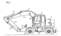
- the present invention is ideal in an application in a wheeled hydraulic excavator.
- the wheeled hydraulic excavator includes an undercarriage 1 and a revolving superstructure 2 rotatably mounted atop the undercarriage 1.
- An operator's cab 3 and a work front attachment 4 constituted with a boom 4a, an arm 4b and a bucket 4c are provided at the revolving superstructure 2.
- the boom 4a is raised/lowered as a boom cylinder 4d is driven, the arm 4b is raised/lowered as an arm cylinder 4e is driven and the bucket 4c is engaged in a dig/dump operation as a bucket cylinder 4f is driven.
- a traveling motor 5, which is hydraulically driven, is provided at the undercarriage 1, and the rotation of the traveling motor 5 is transmitted to wheels 6 (tires) via a drive shaft and an axle.
- FIG. 2 is a circuit diagram of a traveling hydraulic circuit in the wheeled hydraulic excavator shown in FIG. 1.
- oil output from a variable-displacement main pump 11 driven by an engine (prime mover) 40, with its direction and flow rate controlled through a control valve 12, is supplied to the traveling motor 5 via a brake valve 14 which includes a built-in counter-balance valve 13.
- the degree of swash angle or displacement amount of the main pump 11 is adjusted by a pump regulator 11a.
- a pilot circuit includes a pilot pump 21, a pilot valve 22 that generates a secondary pilot pressure in response to an operation of a travel pedal 22a, a slow return valve 23 connected to the pilot valve 22, which delays the return of the oil to the pilot valve 22, and a forward/backward switching valve 24 that is switched to a forward setting (F position), a backward setting (R position) or a neutral setting (N position) in response to an operation of a forward/backward selector switch (not shown).
- a pressure sensor 31 is connected between the slow return valve 23 and the forward/backward switching valve 24, and a pressure Pt corresponding to the extent to which the travel pedal 22a is operated is detected with the pressure sensor 31.
- the forward/backward switching valve 24 is set to the F position or the R position through a switch operation and then the travel pedal 22a is operated, a pilot pressure originating from the pilot pump 21 is applied to the control valve 12.
- the control valve 12 is switched, the pressure oil from the main pump 11 is applied to the traveling motor 5 via the control valve 12 and the traveling motor 5 rotates at a speed corresponding to the extent to which the pedal has been operated, thereby causing the vehicle to travel.
- the pilot valve 22 cuts off the pressure oil from the pilot pump 21, and its outlet port comes into communication with a reservoir.
- the pressure oil which has been applied to the pilot port of the control valve 12 is caused to return to the reservoir via the forward/backward switching valve 24, the slow return valve 23 and the pilot valve 22.
- the returning oil is restricted through a restrictor at the slow return valve 23 and thus, the control valve 12 is gradually switched to the neutral position.
- the vehicle body keeps traveling with the inertial force, and the traveling motor 5 switches from the motor operation to a pump operation during which the B port side in the figure is used for intake and the A port side in the figure is used for outlet if the vehicle is traveling forward (the intake port and the outlet port are reversed if the vehicle is traveling backward).
- the pressure oil from the traveling motor 5 is restricted through a restrictor (restrictor at the neutral position) at the counter-balance valve 13, the pressure between the counter-balance valve 13 and the traveling motor 5 rises and is applied to the traveling motor 5 as a braking pressure.
- the traveling motor 5 imparts a braking torque to apply braking to the vehicle. If the quantity of oil being taken in during the pump operation becomes low, more oil is delivered from a make-up port 15 to supplement the supply to the traveling motor 5.
- the maximum level that the braking pressure achieves is regulated through relief valves 16 and 17.
- the travel pedal 22a If the travel pedal 22a is released on a downhill slope, a hydraulic brake is generated and thus, the vehicle with the brake applied thereto travels downhill under inertia, as in the deceleration operation described above. Since the level of the inertial force of the vehicle is higher under these circumstances compared to the inertial force manifesting when the travel pedal 22a is released while the vehicle is traveling on level ground, oil must be supplemented in a large enough quantity from the make-up port 15 in order to prevent cavitation. For this reason, according to the present invention the rotation speed of the engine 40 during the deceleration operation is controlled as described later so as to prevent the shortage of make-up flow rate due to insufficient make-up pressure.
- FIG. 3 shows a hydraulic circuit of the boom cylinder unit, representing an example of a work hydraulic circuit.
- This hydraulic circuit includes a main pump 26, the boom cylinder 4d that is caused to extend/contract by pressure oil from the main pump 26, a control valve 27 that controls the flow of the pressure oil from the main pump 26 to the boom cylinder 4d, the pilot pump 21 and a pilot valve 28 driven via an operating lever 28a.
- hydraulic circuits of the other work actuators are similar to that shown in FIG. 3.
- the pilot valve 28 In response to an operation of the operating lever 28a, the pilot valve 28 is driven in correspondence to the extent to which the operating lever 28a has been operated and a pilot pressure achieve by lowering the pressure from the pilot pump 21 is applied to the control valve 27.
- a pilot pressure achieve by lowering the pressure from the pilot pump 21 is applied to the control valve 27.
- the pressure oil from the main pump 26 is guided to the boom cylinder 4d via the control valve 27 and, as the boom cylinder 4d extends/contracts, the boom 4a is raised/lowered.
- the hydraulic circuit may dispense with the main pump 26 and, in such a case, the cylinder 4d can be driven with the pressure oil from the main pump 11.
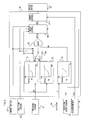
- FIG. 4 is a block diagram of a control circuit that controls the rotation speed of the engine 40.
- a governor lever 41 of the engine 40 is connected to a pulse motor 43 via a link mechanism 42 and the engine rotation speed is adjusted with the rotation of the pulse motor 43. Namely, the engine rotation speed increases as the pulse motor 43 rotates forward, and the engine rotation speed decreases with a reverse rotation of the pulse motor 43.
- a potentiometer 44 is connected to the governor lever 41 via the link mechanism 42, and the governor lever angle corresponding to the rotation speed of the engine 40, which is detected with the potentiometer 44, is input to the control circuit 30 as an engine control rotation speed N ⁇ .
- the control circuit 30 is connected with the pressure sensor 31 that detects the pilot pressure Pt corresponding to the extent to which the travel pedal 22a is operated, a brake switch 32, a position sensor 33 that detects the position to which the forward/backward switching valve 24 is switched, a detector 34 that detects the extent X to which an operating member (e. g. , a fuel lever) for issuing a rotation speed command (not shown) is operated and a rotation speed sensor 35 that detects the rotation speed of the traveling motor 5.
- an operating member e. g. , a fuel lever
- a work or traveling signal is output from the brake switch 32.
- a parking brake is canceled and the operation of a service brake is enabled through a brake pedal.
- the parking brake and the service brake are both engaged.
- the parking brake is engaged.
- the brake switch 32 is switched to the traveling position, it outputs an off signal, whereas it outputs an on signal when it is switched to the work or parking position.
- the rotation speed control circuit 30 executes the following arithmetic operation and outputs a control signal to the pulse motor 43.
- FIG. 5 is a conceptual diagram illustrating in detail the rotation speed control circuit 30.
- the relationships between the detection value Pt provided by the pressure sensor 31 and a target rotation speed Nt and between the detection value Pt and a target rotation speed Nd are stored in memory in advance at rotation speed calculation units 51 and 52 respectively as shown in the figure, and the target rotation speeds Nt and Nd matching the extent to which the travel pedal 22a is operated are individually calculated based upon the characteristics of these relationships.
- the characteristics stored in memory at the rotation speed calculation unit 51 are the characteristics suited for traveling
- the characteristics stored in memory at the rotation speed calculation unit 52 are the characteristics suited for work performed by using the work attachment 4.
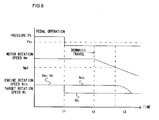
- the target rotation speed Nt increases in a steeper slope compared to the target rotation speed Nd, and a maximum value Ntmax of the target rotation speed Nt is greater than a maximum value Ndmax of the target rotation speed Nd.
- the relationship between the detection value X provided by the detector 34 and a target rotation speed (rotation speed setting) Nx is stored in memory in advance at a rotation speed calculation unit 53 as shown in the figure, and the target rotation speed Nx corresponding to the extent to which the fuel lever is operated is calculated based upon the characteristics of the relationship. It is to be noted that a maximum value Nxmax of the target rotation speed Nx is set equal to the maximum value Ndmax at the rotation speed calculation unit 52.
- a selection unit 54 selects one of the target rotation speeds Nt and Nd provided by the rotation speed calculation units 51 and 52, based upon the signals provided from the brake switch 32, the position sensor 33 and the pressure sensor 31. If the brake switch 32 has been switched to the traveling position (an off signal is output), the forward/backward switching valve 24 is set at a position other than the neutral position and the pilot pressure Pt representing the extent of the operation of the travel pedal 22a is greater than a predetermined value (e.g., 0), i.e., if the vehicle is traveling, the target rotation speed Nt is selected, and the target rotation speed Nd is selected otherwise, i.e., under non-traveling conditions.
- a maximum value selection unit 55 compares the target rotation speed Nt or Nd selected by the selection unit 54 with the target rotation speed Nx calculated at the rotation speed calculation unit 53 and selects the larger value as Nmax.
- a delay control unit 56 calculates a rotation speed command value Nin through the procedure shown in FIG. 6 based upon the selected rotation speed Nmax and the signals provided from the brake switch 32, the position sensor 33, the pressure sensor 31 and the rotation speed sensor 35.
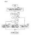
- a servo control unit 57 compares the rotation speed command value Nin calculated at the delay control unit 56 with the control rotation speed N ⁇ corresponding to the displacement quantity of the governor lever 41 detected with the potentiometer 44. Then, it controls the pulse motor 43 through the procedure shown in FIG. 7 so as to match the two values.
- step S1 in FIG. 6 the value selected at the maximum value selection unit 55 and the signals from the sensors 31, 33 and 35 and from the switch 32 are read.
- step S2 a decision is made with regard to the value indicated by a traveling flag in step S2.
- the traveling flag is set to 1 if the vehicle is traveling and is set to 0 if the vehicle is not traveling. If it is decided in step S2 that the traveling flag is set to 1 (traveling), the operation proceeds to step S3 to make a decision with regard to the value indicated by a deceleration flag.
- steps S4, S5 and S13 the deceleration flag is set to 1 during a deceleration but is set to 0 otherwise.
- step S4 to make a decision as to whether or not a deceleration operation is to start by checking the signal provided from the pressure sensor 31. If the extent to which the travel pedal 22a is depressed has become reduced and the pressure detection value Pt has become equal to or less than a predetermined value Pt1, it is judged that a deceleration operation is to start. If an affirmative decision is made in step S4, the operation proceeds to step S5, whereas the operation proceeds to step S13 if a negative decision is made in step S4. In step S5, the deceleration flag is set to 1, and the deceleration flag is set to 0 in step S13.
- step S7 a decision is made as to whether or not the motor rotation speed Nm detected with the rotation speed sensor 35 is equal to or less than a predetermined value Nm1 set in advance.
- This processing is executed to judge whether or not the engine rotation speed is to be allowed to slow down and the predetermined value Nm1 is set by taking into consideration the level of the make-up pressure required for downhill traveling. Namely, the predetermined value Nm1 becomes larger as the extent of the decrease in the make-up pressure due to the speed reduction becomes greater.
- step S7 If an affirmative decision is made in step S7, the operation proceeds to step S8 to gradually decrease the rotation speed command value Nin at a predetermined rate until it becomes equal to the target rotation speed Nt, which is calculated based upon the extent of the operation of the travel pedal 22a (the pressure detection value Pt). In other words, the rotation speed command value Nin is slowed down or gradually decreased. It is to be noted that the rate at which the rotation speed command value Nin is reduced may be altered as time passes or the rate at which the rotation speed command value Nin is decreasedmay be altered in correspondence to the level of the rotation speed. If a negative decision is made in step S7, the operation proceeds to step S9 to substitute a previous value Ninb for the rotation speed command value Nin.
- step S2 If it is decided in step S2 that the traveling flag is set to 0 (the vehicle is not traveling), the operation proceeds to step S10 to make a decision as to whether or not the vehicle is to start traveling. If the brake switch 32 has been switched to the traveling position (an off signal is output), the forward/backward switching valve 24 is set to a position other than the neutral position and the pilot pressure Pt is greater than the predetermined value, it is decided that the vehicle is to start traveling, and in this case, the operation proceeds to step S11. Otherwise, the operation proceeds to step S12. In step S11, the traveling flag is set to 1, whereas the traveling flag is set to 0 in step S12. Next, the deceleration flag is set to 0 in step S13 as mentioned earlier before the operation proceeds to step S14. In step S14, the rotation speed Nmax selected at the maximum value selection unit 55 is set as the rotation speed command value Nin.
- step S3 If, on the other hand, it is decided in step S3 that the deceleration flag is set to 1 (a deceleration operation is in progress), the operation proceeds to step S6 to make a decision as to whether or not the deceleration operation is terminated. In this case, it is decided that the deceleration operation has just been canceled if, for instance, the travel pedal 22a has been depressed to an extent to which the pressure detection value Pt is greater than the predetermined value Pt1. If an affirmative decision is made in step S6, the operation proceeds to step S13, whereas the operation proceeds to step S15 if a negative decision is made. In step S15, a decision is made as to whether or not the deceleration control to be executed in step S7 and subsequent steps is to end.
- This decision is made by comparing the rotation speed command value Nin determined through the previous processing with the target rotation speed Nt (the target rotation speed Nt calculated based upon the pressure detection value Pt) indicated in response to the command issued through the operation of the travel pedal 22a. If Nin ⁇ Nt, it is judged that the deceleration control is to end, to proceed to step S16, but the operation proceeds to step S7 otherwise. Namely, it is judged that the deceleration control is to end at the time point at which the rotation speed command value Nin becomes equal to the target rotation speed Nt indicated in the command issued through the travel pedal 22a (at the time point at which the rotation speed command value Nin becomes equal to the rotation speed indicated in the command issued by the operator).
- step S16 a decision is made as to whether or not the vehicle is traveling, as in step S10, and the operation proceeds to step S13 if an affirmative decision is made, whereas the operation proceeds to step S17 if a negative decision is made.
- step S17 the traveling flag is set to 0, before the operation proceeds to step S13.
- step S21 the rotation speed command value Nin set at the delay control unit 56 and the control rotation speed N ⁇ detected with the potentiometer 44 are individually read in step S21 in FIG. 7. Then, in step S22, the results of subtracting Nin from N ⁇ are stored as a rotation speed difference A in memory, and in step S23, a decision is made as to whether or not
- the control rotation speed N ⁇ is greater than the rotation speed command value Nin, i.e., the control rotation speed is higher than the target rotation speed and, accordingly, a signal constituting a command for a motor reverse rotation is output to the pulse motor 43 in step S25 in order to lower the engine rotation speed.
- the pulse motor 43 rotates in the reverse direction, thereby lowering the engine rotation speed.
- step S26 a signal constituting a command for a motor forward rotation is output in step S26 in order to raise the engine rotation speed.
- the pulse motor 43 rotates forward, thereby raising the engine rotation speed.
- step S27 the operation proceeds to step S27 to output a motor stop signal and, as a result, the engine rotation speed is sustained at a constant level.
- the brake switch 32 is set to the traveling position and the forward/backward selector switch is set to the forward position or the backward position when the vehicle is to travel.
- the control valve 12 is switched in correspondence to the extent of the pedal operation and the traveling motor 5 is caused to revolve by the pressure oil from the main pump 11.
- the traveling flag and the deceleration flag are respectively set to 1 and 0 and the target rotation speed Nt having been selected at the selection unit 54 is set as the rotation speed command value Nin at the delay control unit 56 (step S14) .
- control is implemented to set the engine rotation speed equal to the target rotation speed Nt.
- the engine rotation speed is adjusted in correspondence to the extent to which the travel pedal 22a is operated in conformance to the characteristics stored in memory at the rotation speed calculation unit 51. As a result, desirable acceleration is achieved, an improvement in fuel efficiency is achieved and the level of noise is reduced.
- the traveling pilot pressure Pt becomes equal to or less than the predetermined value Pt1
- the traveling flag and the deceleration flag are both set to 1 at the delay control unit 56
- the rotation speed command value Nin is left unchanged from the control rotation speed at the deceleration operation start (step S9) .
- the engine rotation speed is sustained at a constant level, as shown in FIG. 8, and thus, the quantity of oil output from the pump does not decrease greatly.
- cavitation can be prevented.
- the rotation speed command value Nin is gradually decreased (step S8).
- the engine rotation speed is slowed down, as shown in FIG. 8. Since the motor rotation speed is low, the make-up pressure does not need to be as high as that required for downhill traveling, and cavitation can be prevented effectively enough by slowing down the engine rotation speed.
- the engine rotation speed is continuously slowed down until the rotation speed command value Nin becomes equal to or less than the target rotation speed Nt. Once the rotation speed command value Nin is lowered to the target rotation speed Nt, the engine rotation speed is set to the value Nmax corresponding to the extent to which the travel pedal 22a is operated (step S15 -> step S13).
- step S6 If, on the other hand, the travel pedal 22a is operated and the traveling pilot pressure Pt increases to a level greater than the predetermined value Pt1 while the vehicle is decelerating, the deceleration operation is terminated and the deceleration flag is set to 0 (step S6 -> step S13). In response, the process of slowing down the engine rotation speed is stopped, and the engine rotation speed is immediately reset to the value Nmax corresponding to the extent to which the travel pedal 22a is operated (step S14).
- the brake switch 32 is set to the work position and the forward/backward selector switch is set to the neutral position.
- the control valve 27 is switched in correspondence to the extent to which the operating lever is operated, thereby driving the boom cylinder 4d.
- the maximum value selection unit 55 makes a selection from the target rotation speed Nd and the target rotation speed Nx corresponding to the extent of the fuel lever operation for the larger value. Accordingly, by setting in advance the target rotation speed Nx to a value suited to the particular nature of the work to be undertaken via the fuel lever, the engine rotation speed is not allowed to increase suddenly during the work to improve the operability and fuel efficiency. Since the slope of the characteristics stored in the rotation speed calculation unit 53 is small, the target rotation speed Nx can be set with ease.
- the engine rotation speed is sustained at a specific level to compensate for an insufficient make-up pressure when the motor rotation speed Nm is greater than the predetermined value Nm1, whereas the engine rotation speed is slowed down when the motor rotation speed is equal to or less than the predetermined value Nm1 since a sufficient level of make-up pressure is assured.
- the oil is supplied with a sufficiently high make-up flow rate to reliably prevent the occurrence of cavitation.
- the engine rotation speed is adjusted in correspondence to the extent to which the travel pedal 22a is operated to achieve desirable acceleration. If the travel pedal 22a is operated while gradually reducing the engine rotation speed, the process of slowing down the engine rotation speed or speed reduction is immediately terminated and, as a result, good acceleration is achieved even when the speed reduction process has been in progress.
- the embodiment can be adopted equally effectively when the vehicle is not traveling downhill but a sufficient level of make-up pressure cannot be achieved against the inertial force of the vehicle body.
- the second embodiment differs from the first embodiment in the processing executed by the delay control unit 56. Namely, the engine rotation speed is slowed down if the motor rotation speed Nm is equal to or less than the predetermined value Nm1 during the deceleration operation in the first embodiment. Instead, the engine rotation speed is slowed down for the deceleration operation and subsequently, if the motor rotation speed Nm is judged to be greater than the predetermined value Nm1, the speed reduction operation is disabled in the second embodiment.
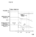
- FIG. 9 presents a flowchart of the processing procedure at the delay control unit 56 of the prime mover control device achieved in the second embodiment. It is to be noted that the same step numbers are assigned to steps in which processing identical to that in FIG. 6 is executed and the following explanation focuses on the differences from the processing in FIG. 6.
- step S4 after it is decided in step S4 that a deceleration operation is to start, the deceleration flag is set to 1 in step S5 and a timer is started in step S21. Subsequently, a decision is made in step S22 as to whether or not the time count by the timer now indicates a predetermined length of time T1. The operation proceeds to step S7 if an affirmative decision is made, but the operation skips step S7 and proceeds to step S8 if a negative decision is made.
- the rotation speed command value Nin is gradually decreased until the predetermined length of time T1 elapses (step S22 -> step S8).
- the engine rotation speed slows down, as illustrated in the figure between the time point t11 and a time point t12.
- the make-up pressure too, becomes lowered, which increases the braking force applied to the vehicle.
- the motor rotation speed Nm gradually becomes lower, as shown in the figure.
- the predetermined length of time T1 is set to a value at which at least the occurrence of cavitation is prevented.
- step S9 if the motor rotation speed Nm is greater than the predetermined value Nm1 at the time point t12, the engine rotation speed stops slowing down and the engine rotation speed is sustained at the current value, as indicated by the solid line in FIG. 10 (step S9) . Then, as the vehicle finishes its downhill travel at a time point t13 and the motor rotation speed Nm becomes equal to or less than the predetermined value Nm1 at a time point t14 the process of slowing down the engine rotation speed is started (step S8) . If, on the other hand, the motor rotation speed Nm is equal to or less than the predetermined value Nm1 at the time point t12 following the predetermined length of time T1, the engine rotation speed continues to slow down, as indicated by the dotted line in FIG. 10.
- step S8 is executed to slow down the engine rotation speed.
- the speed reduction characteristics (the characteristics manifesting between the time points t11 and t12) at the start of the deceleration operation and the speed reduction characteristics manifesting (after the time point t12 or after the time point t14) when the motor rotation speed Nm is equal to or less than the predetermined value Nm1 are identical to each other.
- the engine rotation speed Nm is equal to or less than the predetermined value Nm1 after the predetermined length of time T1 elapses, the engine rotation speed can be smoothly slowed down as indicated by the dotted line in FIG. 10.
- the engine rotation speed may instead be slowed down when the engine rotation speed decreases by a predetermined extent. Namely, instead of executing the processing in steps S21 and S22, a decision may be made as to whether or not the engine rotation speed has become lower by the predetermined extent and then the operation than may proceed to step S7 if an affirmative decision is made, whereas the engine rotation speed may be slowed down in step S8 if a negative decision is made.
- the speed reduction characteristics manifesting (between the time points t11 and t12) at the start of the deceleration operation and the speed reduction characteristics manifesting (after the time point t12 or the time point t14) when the motor rotation speed Nm is equal to or less than the predetermined value Nm1 may be different from each other.
- a potentiometer may be directly mounted at the travel pedal 22a to detect the extent of its operation instead.
- a timer that measures the length of time over which the travel pedal 22a is held down, i.e., the length of time over which pressure is detected by the pressure sensor 31, may be provided as a means for traveling state detection, and in such a case, the vehicle may be judged to be in a traveling state if the travel pedal 22a remains held down over a predetermined length of time or longer.
- the start of the decelerating operation may be detected when the travel pedal 22a is not being operated, or the deceleration operation may be detected when the extent of pedal operation has decreased by at least a predetermined degree.
- the deceleration operation may be detected by comparing the previous operating pressure (detected with the pressure sensor 31) with the current operating pressure and, in such a case, a deceleration may be judged to be occurring if the current operating pressure is smaller than the previous operating pressure.
- the rotation speed of the traveling motor 5 may instead be indirectly detected by using a vehicle speed sensor.
- the engine rotation speed may be adjusted in correspondence to the rotation speed of the traveling motor 5 during the deceleration operation. In other words, the engine rotation speed may be set higher as the rotation speed of the traveling motor 5 increases.
- a wheeled hydraulic excavator represents an example of a construction machine in which the present invention may be adopted
- the present invention may also be adopted in other types of construction machines such as non-wheel construction machines.
Abstract
Description
Claims (5)
- A prime mover control device of a construction machine that includes:a hydraulic pump driven by a prime mover;a hydraulic traveling motor driven with pressure oil output from the hydraulic pump; anda control valve that controls a flow of the pressure oil from the hydraulic pump to the hydraulic motor in response to an operation of an operating member, comprising:a deceleration detection means for detecting a deceleration operation at the operating member;a rotation speed detection means for detecting a rotation speed of the hydraulic motor; anda prime mover rotation speed control means for executing speed reduction control of the rotation speed of the prime mover based upon detection results provided by the rotation speed detection means if the deceleration operation is detected by the deceleration detection means and for controlling the rotation speed of the prime mover in correspondence to an operation of the operating member which is detected to be other than the deceleration operation.
- A prime mover control device of a construction machine according to claim 1, wherein:when the deceleration operation is detected by the deceleration detection means, the rotation speed of the prime mover is sustained at a constant level if the motor rotation speed detected by the rotation speed detection means is greater than a predetermined value and the rotation speed of the prime mover is gradually reduced if the detected motor rotation speed is equal to or less than the predetermined value under the speed reduction control executed by the prime mover rotation speed control means.
- A prime mover control device of a construction machine according to claim 1, wherein:when the deceleration operation is detected by the deceleration detection means, the rotation speed of the prime mover is gradually reduced over a predetermined length of time and then following the predetermined length of time, the rotation speed of the prime mover is sustained at a constant level if the motor rotation speed detected by the rotation speed detection means is greater than a predetermined value but the rotation speed of the prime mover is gradually reduced if the detected motor rotation speed is equal to or less than the predetermined value, under the speed reduction control executed by the prime mover rotation speed control means.
- A prime mover control device of a construction machine according to claim 1, wherein:when the deceleration operation is detected by the deceleration detection means, the rotation speed of the prime mover is gradually reduced by a predetermined degree, and after the rotation speed of the prime mover is reduced by the predetermined degree, the rotation speed of the prime mover is sustained at a constant level if the motor rotation speed detected by the rotation speed detection means is greater than a predetermined value but the rotation speed of the prime mover is gradually reduced if the detected motor rotation speed is equal to or less than the predetermined value, under the speed reduction control executed by the prime mover rotation speed control means.
- A wheeled hydraulic excavator, comprising:a hydraulic pump driven by a prime mover;a hydraulic traveling motor driven with pressure oil output from the hydraulic pump;a control valve that controls a flow of the pressure oil from the hydraulic pump to the hydraulic motor in response to an operation of an operating member; anda prime mover control device according to any one of claims 1 through 4.
Applications Claiming Priority (1)
| Application Number | Priority Date | Filing Date | Title |
|---|---|---|---|
| PCT/JP2002/009966 WO2004029435A1 (en) | 2002-09-26 | 2002-09-26 | Prime mover controller of construction machine |
Publications (4)
| Publication Number | Publication Date |
|---|---|
| EP1544440A1 true EP1544440A1 (en) | 2005-06-22 |
| EP1544440A4 EP1544440A4 (en) | 2007-04-18 |
| EP1544440B1 EP1544440B1 (en) | 2009-06-03 |
| EP1544440B8 EP1544440B8 (en) | 2010-02-17 |
Family
ID=32040308
Family Applications (1)
| Application Number | Title | Priority Date | Filing Date |
|---|---|---|---|
| EP02807863A Expired - Lifetime EP1544440B8 (en) | 2002-09-26 | 2002-09-26 | Prime mover controller of a construction machine. |
Country Status (6)
| Country | Link |
|---|---|
| US (1) | US7273124B2 (en) |
| EP (1) | EP1544440B8 (en) |
| JP (1) | JP3902627B2 (en) |
| CN (1) | CN100354513C (en) |
| DE (1) | DE60232553D1 (en) |
| WO (1) | WO2004029435A1 (en) |
Cited By (4)
| Publication number | Priority date | Publication date | Assignee | Title |
|---|---|---|---|---|
| EP1947316A1 (en) * | 2005-11-01 | 2008-07-23 | Yanmar Co., Ltd. | Engine controller of hydraulic shovel |
| EP2095987A1 (en) * | 2008-02-26 | 2009-09-02 | Kobelco Cranes Co., Ltd. | Power transmission apparatus of working vehicle |
| WO2013037500A1 (en) * | 2011-09-15 | 2013-03-21 | Bomag Gmbh | Method for driving a drive train of a vehicle and apparatus for carrying out the method |
| EP2791492A4 (en) * | 2011-12-13 | 2015-12-30 | Scania Cv Ab | Device and method for regulating the speed of an engine in response to extra load |
Families Citing this family (26)
| Publication number | Priority date | Publication date | Assignee | Title |
|---|---|---|---|---|
| US8403098B2 (en) * | 2005-02-28 | 2013-03-26 | Caterpillar Inc. | Work machine hydraulics control system |
| JP2007085405A (en) * | 2005-09-20 | 2007-04-05 | Kobelco Cranes Co Ltd | Travel stabilizing device for hydraulic drive type working vehicle |
| JP4855852B2 (en) * | 2006-07-04 | 2012-01-18 | 日立建機株式会社 | Motor controller for construction machinery |
| US7798272B2 (en) * | 2006-11-30 | 2010-09-21 | Caterpillar Inc | Systems and methods for controlling slip of vehicle drive members |
| WO2008081856A1 (en) * | 2006-12-28 | 2008-07-10 | Hitachi Construction Machinery Co., Ltd. | Travel control device for hydraulic traveling vehicle |
| KR101112137B1 (en) * | 2009-07-29 | 2012-02-22 | 볼보 컨스트럭션 이큅먼트 에이비 | Control System and Method For Reducing Change Of RPM In Hybrid Type Construction Machine |
| US8401753B2 (en) * | 2009-11-23 | 2013-03-19 | Caterpillar Inc. | Automatic downhill speed control system |
| JP5228000B2 (en) * | 2010-05-26 | 2013-07-03 | 日立建機株式会社 | Hybrid construction machine |
| KR101799101B1 (en) * | 2010-08-23 | 2017-11-20 | 두산인프라코어 주식회사 | Apparatus and method for recognizing working pattern in construction machine |
| JP5747533B2 (en) * | 2011-02-02 | 2015-07-15 | コベルコ建機株式会社 | Swivel work machine |
| WO2012150651A1 (en) * | 2011-05-02 | 2012-11-08 | コベルコ建機株式会社 | Rotation-type working machine |
| WO2013035425A1 (en) * | 2011-09-07 | 2013-03-14 | 日立建機株式会社 | Construction machine |
| US9097341B2 (en) * | 2012-01-26 | 2015-08-04 | Caterpillar Inc. | Brake system having a brake capacity test mode for a machine having a hydrostatic drivetrain |
| JP5959874B2 (en) | 2012-02-15 | 2016-08-02 | 日立建機株式会社 | Hybrid work vehicle |
| JP5970898B2 (en) * | 2012-03-26 | 2016-08-17 | コベルコ建機株式会社 | Power transmission device and hybrid construction machine equipped with the same |
| JP5161386B1 (en) * | 2012-06-22 | 2013-03-13 | 株式会社小松製作所 | Wheel loader and wheel loader control method |
| DE102012020821B4 (en) * | 2012-10-23 | 2021-07-15 | Liebherr-Werk Ehingen Gmbh | Emergency drive for a construction device and method for operating the emergency drive |
| JP6150740B2 (en) * | 2014-02-20 | 2017-06-21 | 日立建機株式会社 | Construction machinery |
| US20170121930A1 (en) * | 2014-06-02 | 2017-05-04 | Komatsu Ltd. | Construction machine control system, construction machine, and method of controlling construction machine |
| JP6389101B2 (en) * | 2014-10-29 | 2018-09-12 | 古河ユニック株式会社 | Pressure oil supply amount control device for vehicle-mounted crane and vehicle-mounted crane including the same |
| US10801523B2 (en) * | 2017-11-08 | 2020-10-13 | Clark Equipment Company | Hydraulic circuit for travel motor |
| FR3096698B1 (en) * | 2019-06-03 | 2021-04-30 | Manitou Bf | Load handling machine |
| CN110344985B (en) * | 2019-06-06 | 2021-03-19 | 东南大学 | Wireless control device and method for chassis system of heavy vehicle |
| US11371209B2 (en) | 2019-06-24 | 2022-06-28 | Deere & Company | Work vehicle with switchable propulsion control system |
| JP7301712B2 (en) * | 2019-10-28 | 2023-07-03 | 株式会社クボタ | work machine |
| CN113187782B (en) * | 2021-05-07 | 2022-08-02 | 潍柴动力股份有限公司 | Control method, device and equipment of closed hydraulic system and storage medium |
Citations (3)
| Publication number | Priority date | Publication date | Assignee | Title |
|---|---|---|---|---|
| EP0424088A2 (en) * | 1989-10-16 | 1991-04-24 | Honda Giken Kogyo Kabushiki Kaisha | Method of controlling automatic transmission |
| EP0761491A2 (en) * | 1991-03-29 | 1997-03-12 | Hitachi Construction Machinery Co., Ltd. | Control device for hydraulically propelled work vehicle |
| EP1006298A2 (en) * | 1994-11-09 | 2000-06-07 | Komatsu Ltd. | Speed change control method of hydraulic driving apparatus for vehicles and speed changing device |
Family Cites Families (10)
| Publication number | Priority date | Publication date | Assignee | Title |
|---|---|---|---|---|
| US4240515A (en) * | 1978-12-08 | 1980-12-23 | Kirkwood Robert W | Vehicle hydraulic drive system |
| US4554992A (en) * | 1983-09-09 | 1985-11-26 | Fmc Corporation | Hydraulically operated four wheel sweeper |
| JP2695645B2 (en) * | 1988-07-06 | 1998-01-14 | 日立建機株式会社 | Motor control device for hydraulically driven vehicle |
| JP2974733B2 (en) * | 1989-07-13 | 1999-11-10 | 日立建機株式会社 | Engine speed control device for hydraulic traveling vehicle |
| WO1992014046A1 (en) * | 1991-02-05 | 1992-08-20 | Hitachi Construction Machinery Co., Ltd. | System for controlling revolution frequency of prime mover in hydraulically driven vehicle |
| JP2634330B2 (en) | 1991-02-08 | 1997-07-23 | 日立建機株式会社 | Engine speed control device for hydraulically driven vehicle |
| JP3400178B2 (en) * | 1995-03-31 | 2003-04-28 | 日立建機株式会社 | Travel control device for hydraulically driven vehicle |
| US6349253B1 (en) * | 1998-11-13 | 2002-02-19 | Cummins Engine, Inc. | System and method for controlling downhill vehicle operation |
| JP4121687B2 (en) * | 2000-04-14 | 2008-07-23 | 日立建機株式会社 | Hydraulic traveling vehicle |
| JP4141444B2 (en) * | 2005-01-25 | 2008-08-27 | 三菱電機株式会社 | In-vehicle engine controller |
-
2002
- 2002-09-26 EP EP02807863A patent/EP1544440B8/en not_active Expired - Lifetime
- 2002-09-26 JP JP2004539438A patent/JP3902627B2/en not_active Expired - Fee Related
- 2002-09-26 WO PCT/JP2002/009966 patent/WO2004029435A1/en active Application Filing
- 2002-09-26 US US10/528,067 patent/US7273124B2/en not_active Expired - Fee Related
- 2002-09-26 DE DE60232553T patent/DE60232553D1/en not_active Expired - Lifetime
- 2002-09-26 CN CNB028296699A patent/CN100354513C/en not_active Expired - Fee Related
Patent Citations (3)
| Publication number | Priority date | Publication date | Assignee | Title |
|---|---|---|---|---|
| EP0424088A2 (en) * | 1989-10-16 | 1991-04-24 | Honda Giken Kogyo Kabushiki Kaisha | Method of controlling automatic transmission |
| EP0761491A2 (en) * | 1991-03-29 | 1997-03-12 | Hitachi Construction Machinery Co., Ltd. | Control device for hydraulically propelled work vehicle |
| EP1006298A2 (en) * | 1994-11-09 | 2000-06-07 | Komatsu Ltd. | Speed change control method of hydraulic driving apparatus for vehicles and speed changing device |
Non-Patent Citations (1)
| Title |
|---|
| See also references of WO2004029435A1 * |
Cited By (7)
| Publication number | Priority date | Publication date | Assignee | Title |
|---|---|---|---|---|
| EP1947316A1 (en) * | 2005-11-01 | 2008-07-23 | Yanmar Co., Ltd. | Engine controller of hydraulic shovel |
| EP1947316A4 (en) * | 2005-11-01 | 2009-04-15 | Yanmar Co Ltd | Engine controller of hydraulic shovel |
| US7908068B2 (en) | 2005-11-01 | 2011-03-15 | Yanmar Co., Ltd. | Engine controller of hydraulic shovel |
| EP2095987A1 (en) * | 2008-02-26 | 2009-09-02 | Kobelco Cranes Co., Ltd. | Power transmission apparatus of working vehicle |
| WO2013037500A1 (en) * | 2011-09-15 | 2013-03-21 | Bomag Gmbh | Method for driving a drive train of a vehicle and apparatus for carrying out the method |
| US9638112B2 (en) | 2011-09-15 | 2017-05-02 | Bomag Gmbh | Method of controlling a power train of a vehicle and device for carrying out said method |
| EP2791492A4 (en) * | 2011-12-13 | 2015-12-30 | Scania Cv Ab | Device and method for regulating the speed of an engine in response to extra load |
Also Published As
| Publication number | Publication date |
|---|---|
| CN1668835A (en) | 2005-09-14 |
| CN100354513C (en) | 2007-12-12 |
| JP3902627B2 (en) | 2007-04-11 |
| WO2004029435A1 (en) | 2004-04-08 |
| EP1544440B1 (en) | 2009-06-03 |
| EP1544440A4 (en) | 2007-04-18 |
| US20060096799A1 (en) | 2006-05-11 |
| EP1544440B8 (en) | 2010-02-17 |
| DE60232553D1 (en) | 2009-07-16 |
| US7273124B2 (en) | 2007-09-25 |
| JPWO2004029435A1 (en) | 2006-01-26 |
Similar Documents
| Publication | Publication Date | Title |
|---|---|---|
| EP1544440B1 (en) | Prime mover controller of a construction machine. | |
| US7398648B2 (en) | Travel control device for hydraulically driven vehicle and hydraulically driven vehicle | |
| US6941688B2 (en) | Hydraulically powered vehicle, and engine rotational speed control method for hydraulically powered vehicle | |
| US7886862B2 (en) | Prime mover control device of construction machine | |
| US7698891B2 (en) | Travel motion control apparatus for hydraulically driven vehicle, hydraulically driven vehicle and wheel hydraulic excavator | |
| US7757486B2 (en) | Engine control device for work vehicle | |
| US20130256053A1 (en) | Work vehicle and control method for work vehicle | |
| US7506717B2 (en) | Hydraulically driven vehicle | |
| US7513110B2 (en) | Control apparatus of construction machine and method for calculating input torque | |
| EP0528042A1 (en) | System for controlling revolution frequency of prime mover in hydraulically driven vehicle | |
| EP2666684B1 (en) | Work vehicle and method for controlling work vehicle | |
| US7607245B2 (en) | Construction machine | |
| JP4589649B2 (en) | Wheel loader clutch control device and wheel loader | |
| JP4282871B2 (en) | Hydraulic traveling vehicle | |
| JP4376009B2 (en) | Control device for work vehicle | |
| KR100680929B1 (en) | Prime mover controller of construction machine | |
| CN116917586A (en) | Work machine and control method for work machine | |
| JPH04258416A (en) | Hydraulic driving device for hydraulic traveling car |
Legal Events
| Date | Code | Title | Description |
|---|---|---|---|
| PUAI | Public reference made under article 153(3) epc to a published international application that has entered the european phase |
Free format text: ORIGINAL CODE: 0009012 |
|
| 17P | Request for examination filed |
Effective date: 20050322 |
|
| AK | Designated contracting states |
Kind code of ref document: A1 Designated state(s): AT BE BG CH CY CZ DE DK EE ES FI FR GB GR IE IT LI LU MC NL PT SE SK TR |
|
| RBV | Designated contracting states (corrected) |
Designated state(s): DE FR GB IT NL SE |
|
| A4 | Supplementary search report drawn up and despatched |
Effective date: 20070319 |
|
| RIC1 | Information provided on ipc code assigned before grant |
Ipc: F02D 29/00 20060101AFI20040414BHEP Ipc: E02F 9/22 20060101ALI20070313BHEP |
|
| 17Q | First examination report despatched |
Effective date: 20071121 |
|
| RTI1 | Title (correction) |
Free format text: PRIME MOVER CONTROLLER OF A CONSTRUCTION MACHINE. |
|
| GRAP | Despatch of communication of intention to grant a patent |
Free format text: ORIGINAL CODE: EPIDOSNIGR1 |
|
| GRAS | Grant fee paid |
Free format text: ORIGINAL CODE: EPIDOSNIGR3 |
|
| RIN1 | Information on inventor provided before grant (corrected) |
Inventor name: TATSUNO, YUKIHIRO Inventor name: SATAKE, HIDETOSHI Inventor name: ICHIMURA, KAZUHIRO |
|
| GRAA | (expected) grant |
Free format text: ORIGINAL CODE: 0009210 |
|
| AK | Designated contracting states |
Kind code of ref document: B1 Designated state(s): DE FR GB IT NL SE |
|
| REG | Reference to a national code |
Ref country code: GB Ref legal event code: FG4D |
|
| REF | Corresponds to: |
Ref document number: 60232553 Country of ref document: DE Date of ref document: 20090716 Kind code of ref document: P |
|
| PG25 | Lapsed in a contracting state [announced via postgrant information from national office to epo] |
Ref country code: SE Free format text: LAPSE BECAUSE OF FAILURE TO SUBMIT A TRANSLATION OF THE DESCRIPTION OR TO PAY THE FEE WITHIN THE PRESCRIBED TIME-LIMIT Effective date: 20090903 |
|
| RAP2 | Party data changed (patent owner data changed or rights of a patent transferred) |
Owner name: HITACHI CONSTRUCTION MACHINERY CO., LTD. |
|
| NLT2 | Nl: modifications (of names), taken from the european patent patent bulletin |
Owner name: HITACHI CONSTRUCTION MACHINERY CO., LTD. Effective date: 20100106 |
|
| PLBE | No opposition filed within time limit |
Free format text: ORIGINAL CODE: 0009261 |
|
| STAA | Information on the status of an ep patent application or granted ep patent |
Free format text: STATUS: NO OPPOSITION FILED WITHIN TIME LIMIT |
|
| 26N | No opposition filed |
Effective date: 20100304 |
|
| GBPC | Gb: european patent ceased through non-payment of renewal fee |
Effective date: 20090926 |
|
| PG25 | Lapsed in a contracting state [announced via postgrant information from national office to epo] |
Ref country code: GB Free format text: LAPSE BECAUSE OF NON-PAYMENT OF DUE FEES Effective date: 20090926 |
|
| REG | Reference to a national code |
Ref country code: FR Ref legal event code: PLFP Year of fee payment: 15 |
|
| PGFP | Annual fee paid to national office [announced via postgrant information from national office to epo] |
Ref country code: IT Payment date: 20160921 Year of fee payment: 15 |
|
| PGFP | Annual fee paid to national office [announced via postgrant information from national office to epo] |
Ref country code: FR Payment date: 20160816 Year of fee payment: 15 |
|
| REG | Reference to a national code |
Ref country code: FR Ref legal event code: ST Effective date: 20180531 |
|
| PG25 | Lapsed in a contracting state [announced via postgrant information from national office to epo] |
Ref country code: FR Free format text: LAPSE BECAUSE OF NON-PAYMENT OF DUE FEES Effective date: 20171002 Ref country code: IT Free format text: LAPSE BECAUSE OF NON-PAYMENT OF DUE FEES Effective date: 20170926 |
|
| PGFP | Annual fee paid to national office [announced via postgrant information from national office to epo] |
Ref country code: NL Payment date: 20200814 Year of fee payment: 19 |
|
| PGFP | Annual fee paid to national office [announced via postgrant information from national office to epo] |
Ref country code: DE Payment date: 20200916 Year of fee payment: 19 |
|
| REG | Reference to a national code |
Ref country code: DE Ref legal event code: R119 Ref document number: 60232553 Country of ref document: DE |
|
| REG | Reference to a national code |
Ref country code: NL Ref legal event code: MM Effective date: 20211001 |
|
| PG25 | Lapsed in a contracting state [announced via postgrant information from national office to epo] |
Ref country code: NL Free format text: LAPSE BECAUSE OF NON-PAYMENT OF DUE FEES Effective date: 20211001 |
|
| PG25 | Lapsed in a contracting state [announced via postgrant information from national office to epo] |
Ref country code: DE Free format text: LAPSE BECAUSE OF NON-PAYMENT OF DUE FEES Effective date: 20220401 |