EP1544104B1 - Nez d'avion avec bouclier - Google Patents
Nez d'avion avec bouclier Download PDFInfo
- Publication number
- EP1544104B1 EP1544104B1 EP04300815A EP04300815A EP1544104B1 EP 1544104 B1 EP1544104 B1 EP 1544104B1 EP 04300815 A EP04300815 A EP 04300815A EP 04300815 A EP04300815 A EP 04300815A EP 1544104 B1 EP1544104 B1 EP 1544104B1
- Authority
- EP
- European Patent Office
- Prior art keywords
- shield
- aircraft
- frame
- aircraft nose
- fingers
- Prior art date
- Legal status (The legal status is an assumption and is not a legal conclusion. Google has not performed a legal analysis and makes no representation as to the accuracy of the status listed.)
- Expired - Lifetime
Links
- 229920001971 elastomer Polymers 0.000 claims abstract description 11
- 239000005060 rubber Substances 0.000 claims abstract description 7
- 239000013013 elastic material Substances 0.000 claims abstract description 4
- 239000000806 elastomer Substances 0.000 claims abstract description 4
- 239000002131 composite material Substances 0.000 claims 1
- 230000000694 effects Effects 0.000 description 3
- 229910052782 aluminium Inorganic materials 0.000 description 2
- XAGFODPZIPBFFR-UHFFFAOYSA-N aluminium Chemical compound [Al] XAGFODPZIPBFFR-UHFFFAOYSA-N 0.000 description 2
- 238000013016 damping Methods 0.000 description 2
- 229910052751 metal Inorganic materials 0.000 description 2
- 230000002093 peripheral effect Effects 0.000 description 2
- 230000001681 protective effect Effects 0.000 description 2
- 230000035939 shock Effects 0.000 description 2
- 230000008961 swelling Effects 0.000 description 2
- 229910000831 Steel Inorganic materials 0.000 description 1
- RTAQQCXQSZGOHL-UHFFFAOYSA-N Titanium Chemical compound [Ti] RTAQQCXQSZGOHL-UHFFFAOYSA-N 0.000 description 1
- 230000000295 complement effect Effects 0.000 description 1
- 238000001514 detection method Methods 0.000 description 1
- 239000000945 filler Substances 0.000 description 1
- 238000010304 firing Methods 0.000 description 1
- 238000012423 maintenance Methods 0.000 description 1
- 230000014759 maintenance of location Effects 0.000 description 1
- 239000002184 metal Substances 0.000 description 1
- 238000009527 percussion Methods 0.000 description 1
- 229920001296 polysiloxane Polymers 0.000 description 1
- 229920001021 polysulfide Polymers 0.000 description 1
- 239000005077 polysulfide Substances 0.000 description 1
- 150000008117 polysulfides Polymers 0.000 description 1
- 239000000565 sealant Substances 0.000 description 1
- 238000007789 sealing Methods 0.000 description 1
- 239000010959 steel Substances 0.000 description 1
- 239000010936 titanium Substances 0.000 description 1
- 229910052719 titanium Inorganic materials 0.000 description 1
Images
Classifications
-
- B—PERFORMING OPERATIONS; TRANSPORTING
- B64—AIRCRAFT; AVIATION; COSMONAUTICS
- B64C—AEROPLANES; HELICOPTERS
- B64C1/00—Fuselages; Constructional features common to fuselages, wings, stabilising surfaces or the like
- B64C1/06—Frames; Stringers; Longerons ; Fuselage sections
-
- B—PERFORMING OPERATIONS; TRANSPORTING
- B64—AIRCRAFT; AVIATION; COSMONAUTICS
- B64C—AEROPLANES; HELICOPTERS
- B64C1/00—Fuselages; Constructional features common to fuselages, wings, stabilising surfaces or the like
- B64C1/06—Frames; Stringers; Longerons ; Fuselage sections
- B64C1/10—Bulkheads
-
- B—PERFORMING OPERATIONS; TRANSPORTING
- B64—AIRCRAFT; AVIATION; COSMONAUTICS
- B64C—AEROPLANES; HELICOPTERS
- B64C1/00—Fuselages; Constructional features common to fuselages, wings, stabilising surfaces or the like
- B64C2001/0054—Fuselage structures substantially made from particular materials
- B64C2001/0081—Fuselage structures substantially made from particular materials from metallic materials
Definitions
- the present invention relates to an aircraft nose having a protective shield.
- This shield is located between a cabin, where pilots are located on the one hand, and a radome in front of the aircraft where are located certain detection equipment such as radar antennas on the other hand.
- the invention aims, for large aircraft, to effectively protect a cabin, a cabin or even a critical compartment of the aircraft, frontal projections at high speed.
- Such projections result essentially from the percussion of birds on the front of the aircraft.
- the radome located at the front of the aircraft is perforated in its central part by the projectile encountered, the internal equipment of the radome are destroyed and the projectile continues its course into the compartment where the driver or pilots . These can then be seriously injured.
- other equipment is present that could be damaged by this shock.
- the tilt of the fuselage at this point avoids the perforation.
- shields are such that these shields are made in the form of assembled panels that rub shoulders with each other. Indeed, at high altitude, the atmospheric pressure is low. To avoid that the passengers of the aircraft lack of air, the cabin is sealed and is, because of the very low external pressure, considered pressurized. Under these conditions, the structures of the aircraft are subjected to internal pressure forces having an effect similar to swelling. This swelling occurs everywhere in the aircraft, and especially at the front of the aircraft, on a front frame cabin that carries the shield. This skeleton, initially flat, is deformed. It then takes advantage of the shield structure in the form of panels to adapt to this deformation while maintaining the sealing and shielding qualities of the shield.
- the shield must fulfill other functions. In particular, it must be light and strong, and also easily lend itself to assembly and disassembly during maintenance of the aircraft.
- the standard stipulates that the shield must withstand firing of birds of weight equal to 4 pounds and launched at a speed of 180 m / second. From this point of view, the multi-panel solution is less effective and less practical to implement than a rigid and resistant panel. We therefore face the following problem, that of making a rigid and resistant panel of large size to mount on a structure itself deformable.
- the shield has metal elements, in practice fingers or pawns, which slide longitudinally in receptacles of the frame (or reciprocally). This sliding allows a radial retention of the fingers relative to a sliding axis of these fingers. Accordingly, the shield has, relative to the frame, a single degree of freedom at the location of each finger, in one direction. We succeed like that to obtain the desired effects. In this case, the shield no longer contributes to the seal which is completely ensured elsewhere.
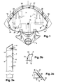
- Figure 1 shows a portion of an aircraft nose having a shield according to the invention.
- the nose of the airplane itself is formed of a front bulb, not shown, which is presented as a half-shell located between Figure 1 and the observer of Figure 1.
- Back of Figure 1, also no represented, is located a cabin where a pilot is held and whose positions of the seats 1 and 2 of piloting have been suggested.
- the fuselage 3 of the aircraft thus determines in the upper part a cabin and in the lower part, not shown, a cargo hold.
- a console 4 attached to the frame of the aircraft.
- the console 4 is intended to carry radar equipment located in a radome forming the bulb.
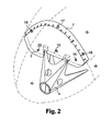
- Figure 2 shows more clearly a cabin area separated from a radome area 6 by the shield 7 of the invention.
- a critical compartment 8 of the aircraft is under cabin area 5.
- the shield 7 may have the purpose of protecting the zone 5 and / or the zone 8 or the zone 5 and partially the zone 8.
- the shield 7 is preferably formed of a thick aluminum front plate 9, a thin aluminum back plate and, in between, a honeycomb core 11.
- the overall stiffness can still be increased by a border.
- the shield as shown has large dimensions: its thickness is about 118 mm and its surface is about 3 m 2 .
- the thickness of the front plate 9 is preferably equal to 2.4 mm, that of the back plate 10 to 0.8 mm, whereas the central honeycomb core, of low density, preferably measures 115 mm. mm.
- the peripheral edge can be made with fillers and sealants (polysulfide, silicone ).
- the shield 7 is thus much larger than the shield panels of the state of the art whose elemental surface was less than 0.5 m 2
- a frame 12 of the aircraft is shown schematically in Figure 3a.
- This frame 12 has the particularity to deform at the time of pressurization of the aircraft relative to the outside air.
- the shield 7 is unique, one-piece and rigid, it was conceivable in the invention to mount it floating on the frame 12.
- the frame 12 comprises fingers or pawns such as 13 which engage in receptacles 14 of the shield 7, or vice versa.
- a receptacle 14 preferably does not pass through the shield 7 from one side to the other. Its depth is limited to a value slightly greater than the height of the fingers 13. In one example, the fingers 13 have a height of 20.5 mm and a diameter of 6.35 mm.
- the fingers 13 are preferably covered with a layer of elastic material, elastomer or rubber, the thickness of which is of the order of 5 mm. Possibly, the fingers 13 can be mounted on the shield, and the receptacles 14 mounted on the frame 12. Similarly, the damping layer of the cylindrical rubber seal can be placed inside the receptacles 14.
- the stroke of the fingers 13 inside the receptacles 14 is of the order of 5.5 mm. It is well below the engagement length of the fingers 13 in the receptacles 14.
- the connections between these two major elements, the frame and the shield comprise in the central part at least three fingers attached to the frame and three receptacles attached to the shield. These retain laterally and vertically the shield in its place.
- this bulky shield has a prepositioning on each side.
- This prepositioning is carried out by general elements of the frame of the aircraft, for example reservations facing the legs of the console 4.
- the fingers 13 have a generally pointed shape. This is for example obtained by forming the end of the fingers 13 themselves by a half-sphere and arranging the damping rubber layer slightly below the main diameter of the terminal sphere of the fingers.
- the shield 7 thus comprises four receptacles 15 to 18, including a central and three peripherals, and optionally two fingers 19 and 20 at the bottom.
- the shield 7 is also maintained on the frame 12 by a set of elastic fasteners.
- This set of fasteners comprises at least, preferably, three springs connecting the front face of the shield to the frame. This number of three, by balancing the forces, keeps the shield in position. To prevent it from vibrating, during the flight, we take advantage of rubber seals that encase the fingers to serve as a damper by friction in the receptacles.
- a spring 21 is fixed on the one hand by an anchor 22 on the frame 13 and on the other hand, by a tab 23 on the thick front plate 9.
- the fasteners such as 21 are here placed in the lower position 24 and 25 of the shield 7.
- FIG. 3c comprise another spring 30 attached, under the same conditions, on the one hand, to the shield 7, and on the other hand, to the frame 12.
- Figure 3c shows, in section at its place, the outer surface 31 of the radome 6 and the outer surface 32 of the cabin area 5.
- the plate 9 and the plate 10 are connected by a metal braid, mountable quickly on the mass of the aircraft.
- the operation of the shield floating link is simple. Lateral and vertical forces are taken up by the fingers and rubber seals. The axial forces resulting from the pressurization of the aircraft are taken up by the springs which tend to press the shield 7 onto the framework 12.
- the central part of the frame is cambered forward and the armor is pushed in the same direction, and the same amount as this camber.
- the springs balance the shield in its new position imposed by the finger-elastomer central links.
- the link 15 located in the center of the frame serves as a pivot.
- the structure 12 is solicited solely for its resistance to the general forces of the aircraft and the shield 7 remains fixed but not constrained.
- the shield being monobloc, it resists perfectly to the shocks of birds. Its structure is particularly optimized to the natural demands of the aircraft and operates with flexibility.
- the connection principle therefore allows the cohabitation between a flexible support, the frame 12, and a monobloc and very rigid shielding. All connecting elements facilitate quick assembly. Prepositioning relieves operators of the bulky weight and bulk of the shield.
- the steel wire spring connections can be replaced by elastomeric latches.
- the first sheet of the shield 9 may advantageously be replaced by a thin titanium sheet.
Landscapes
- Engineering & Computer Science (AREA)
- Mechanical Engineering (AREA)
- Aviation & Aerospace Engineering (AREA)
- Aiming, Guidance, Guns With A Light Source, Armor, Camouflage, And Targets (AREA)
- Details Of Aerials (AREA)
- Moulding By Coating Moulds (AREA)
Description
- La présente invention a pour objet un nez d'avion comportant un bouclier de protection. Ce bouclier de protection est situé entre une cabine, où sont situés les pilotes d'une part, et un radôme en avant de l'avion où sont situés certains équipements de détection tels que des antennes radars d'autre part.
- L'invention a pour but, pour des grands avions, de protéger efficacement une cabine, un habitacle ou bien même un compartiment critique de l'avion, de projections frontales à grande vitesse. De telles projections résultent essentiellement de la percussion de volatiles sur l'avant de l'avion. A grande vitesse, le radôme situé à l'avant de l'avion est perforé dans sa partie centrale par le projectile rencontré, les équipements internes du radôme sont détruits et le projectile continue sa course jusque dans le compartiment où se tiennent le ou les pilotes. Ceux-ci peuvent être alors gravement blessés. Eventuellement, dans une zone située sous le plancher de la cabine, en regard de la soute, dans un compartiment critique de l'avion, d'autres équipements sont présents qui pourraient être endommagés par ce choc. Lorsque le volatile atteint l'avion un peu sur le côté du nez, l'inclinaison du fuselage à cet endroit permet d'éviter la perforation.
- Pour éviter de tels accidents, il est prévu d'interposer un bouclier entre la cabine où se tient le pilote ou bien le compartiment critique de l'avion, et le radôme de l'avion placé à l'avant de l'avion.
- Les constitutions connues des boucliers sont telles que ces boucliers sont réalisés sous forme de panneaux assemblés qui se côtoient les uns les autres. En effet, à haute altitude, la pression atmosphérique est faible. Pour éviter que les passagers de l'avion ne manquent d'air, la cabine est étanche et est, du fait de la très faible pression extérieure, considérée comme pressurisée. Dans ces conditions, les structures de l'avion sont soumises à des forces de pression interne ayant un effet similaire à un gonflement. Ce gonflement se produit partout dans l'avion, et notamment à l'avant de l'avion, sur une ossature avant de cabine qui porte le bouclier. Cette ossature, au départ plane, se déforme. On tire alors parti de la structure du bouclier sous forme de panneaux pour s'adapter à cette déformation tout en conservant les qualités d'étanchéité et de protection du bouclier.
- Cependant, pour les grands avions, le bouclier doit remplir d'autres fonctions. Notamment, il doit être léger et résistant, et par ailleurs se prêter facilement à un montage et un démontage lors des entretiens de l'avion. La norme prévoit que le bouclier doit résister à des tirs de volatiles de poids égal à 4 livres et lancés à une vitesse de 180 m/seconde. De ce point de vue, la solution à panneaux multiples s'avère moins efficace et moins pratique à mettre en oeuvre qu'un panneau rigide et résistant. On est donc confronté au problème suivant, celui de réaliser un panneau rigide et résistant de grande dimension à monter sur une structure elle-même déformable.
- Dans l'invention, on a alors eu l'idée de réaliser un tel panneau monobloc rigide et résistant et de le monter flottant sur l'ossature avant de l'avion. Le flottement est tel que, à l'arrêt, lorsque l'avion ne vole pas et que les pressions sont équilibrées de part et d'autre de la structure avion, le bouclier reste engagé à fond dans l'ossature de l'avion. Par opposition, à haute altitude, lorsque l'ossature avant de l'avion se déforme, le bouclier rigide comporte des éléments métalliques, en pratique des doigts ou des pions, qui coulissent longitudinalement dans des réceptacles de l'ossature (ou réciproquement). Ce coulissement permet un maintien radial des doigts par rapport à un axe de coulissement de ces doigts. En conséquence, le bouclier possède, par rapport à l'ossature, un seul degré de liberté à l'endroit de chaque doigt, dans une seule direction. On réussit comme ça à obtenir les effets recherchés. Dans ce cas, le bouclier ne contribue plus à l'étanchéité qui est complètement assurée par ailleurs.
- L'invention a donc pour objet un nez d'avion comportant un bouclier de protection situé en position intermédiaire d'une part entre une cabine où se tient le pilote, ou un compartiment critique de l'avion, et d'autre part un radôme de l'avion placé à l'avant de l'avion, caractérisé en ce que
- la cabine comporte une ossature avant de cabine,
- le bouclier est unique, monobloc, et rigide, et
- le bouclier rigide est monté flottant sur cette ossature avant.
- L'invention sera mieux comprise à la lecture de la description qui suit et à l'examen des figures qui l'accompagnent. Celles-ci ne sont présentées qu'à titre indicatif et nullement limitatif de l'invention. Les figures montrent :
- Figure 1 : une vue en coupe de face, et partiellement en transparence, du bouclier de l'invention monté sur un nez d'avion ;
- Figure 2 : une représentation en perspective du même bouclier ;
- Figures 3a à 3c : des représentations en coupe de détails du bouclier de l'invention.
- La figure 1 montre une partie d'un nez d'avion comportant un bouclier selon l'invention. Le nez d'avion proprement dit, est formé d'un bulbe avant, non représenté, qui se présente comme une demi-coque situé entre la figure 1 et l'observateur de la figure 1. En arrière de la figure 1, également non représenté, est située une cabine où se tient un pilote et dont on a suggéré les positions des sièges 1 et 2 de pilotage. Le fuselage 3 de l'avion détermine ainsi en partie haute une cabine et en partie basse, non représentée, une soute. En avant du bouclier dans le prolongement de la soute est située une console 4 fixée à l'ossature de l'avion. La console 4 est destinée à porter des équipements radars situés dans un radôme formant le bulbe. La figure 2 montre plus clairement une zone 5 de cabine séparée d'une zone 6 de radôme par le bouclier 7 de l'invention. Un compartiment critique 8 de l'avion se trouve sous la zone 5 de cabine. Le bouclier 7 peut avoir pour objet de protéger la zone 5 et/ou la zone 8 ou la zone 5 et partiellement la zone 8.
- Figure 3a, le bouclier 7 est formé de préférence d'une plaque avant épaisse 9 en aluminium, d'une plaque arrière 10 fine en aluminium et, entre les deux, d'une âme en nid d'abeille 11. La rigidité générale peut encore être augmentée par un bordurage. Le bouclier tel qu'il est représenté a de grandes dimensions : son épaisseur est d'environ 118 mm et sa surface est d'environ 3 m2. L'épaisseur de la plaque avant 9 est de préférence égale à 2,4 mm, celle de la plaque arrière 10 à 0,8 mm, alors que l'âme centrale en nid d'abeille, de faible densité, mesure de préférence 115 mm. La bordure périphérique peut être réalisée avec des mastics de remplissage et des produits d'étanchéité (polysulfure, silicone...). Le bouclier 7 est ainsi bien plus grand que les panneaux de bouclier de l'état de la technique dont la surface élémentaire était inférieure à 0,5 m2
- Une ossature 12 de l'avion est représentée schématiquement figure 3a. Cette ossature 12 présente la particularité de se déformer au moment de la pressurisation de l'avion par rapport à l'air extérieur. Alors que le bouclier 7 est unique, monobloc et rigide, on a eu l'idée, dans l'invention, de le monter flottant sur l'ossature 12. Dans ce but, l'ossature 12 comporte des doigts ou des pions tels que 13 qui s'engagent dans des réceptacles 14 du bouclier 7, ou réciproquement. Un réceptacle 14 ne traverse de préférence pas le bouclier 7 de part en part. Sa profondeur est limitée à une valeur légèrement supérieure à la hauteur des doigts 13. Dans un exemple, les doigts 13 ont une hauteur de 20,5 mm et un diamètre de 6,35 mm. Les doigts 13 sont de préférence recouverts d'une couche de matériau élastique, d'élastomère ou de caoutchouc, dont l'épaisseur est de l'ordre de 5 mm. Eventuellement, les doigts 13 peuvent être montés sur le bouclier, et les réceptacles 14 montés sur l'ossature 12. De même, la couche amortissante du joint cylindrique en caoutchouc peut être placée à l'intérieur des réceptacles 14.
- Lorsque l'ossature se déforme sous l'effet de la pressurisation, la course des doigts 13 à l'intérieur des réceptacles 14 est de l'ordre de 5,5 mm. Elle est bien inférieure à la longueur d'engagement des doigts 13 dans les réceptacles 14. De préférence, les liaisons entre ces deux éléments majeurs, l'ossature et le bouclier, comportent en partie centrale au moins trois doigts fixés à l'ossature et trois réceptacles fixés au bouclier. Ceux-ci retiennent latéralement et verticalement le bouclier à sa place.
- Pour faciliter le montage de ce bouclier encombrant sur l'avant de l'ossature, on dispose d'un prépositionnement de chaque côté. Ce prépositionnement est réalisé par des éléments généraux de l'ossature de l'avion, par exemple des réservations en regard de piétements de la console 4. Pour le positionnement plus précis, de préférence, les doigts 13 ont une forme globalement en pointe. Ceci est par exemple obtenu en formant l'extrémité des doigts 13 proprement dits par une demi-sphère et en disposant la couche de caoutchouc d'amortissement légèrement en-dessous du diamètre principal de la sphère terminale des doigts. Dans l'exemple représenté figure 2, le bouclier 7 comporte ainsi quatre réceptacles 15 à 18, dont un central et trois périphériques, et éventuellement deux doigts 19 et 20 en partie basse.
- Le bouclier 7 est par ailleurs maintenu sur l'ossature 12 par un jeu d'attaches élastiques. Ce jeu d'attaches comporte au moins, de préférence, trois ressorts reliant la face avant du blindage à l'ossature. Ce nombre de trois, par l'équilibrage des forces, maintient le bouclier en position. Pour éviter qu'il ne vibre, au cours du vol, on tire partie des joints de caoutchouc qui enrobent les doigts pour servir d'amortisseur par frottement dans les réceptacles. Par exemple, figure 3b, un ressort 21 est fixé d'une part par un ancrage 22 sur l'ossature 13 et d'autre part, par une patte 23 sur la plaque avant épaisse 9. Les attaches telles que 21 sont ici placées dans la position basse 24 et 25 du bouclier 7. Quatre autres attaches 26, 27, 28 et 29, montrées en coupe sur la figure 3c comportent un autre ressort 30 attaché, dans les mêmes conditions, d'une part, au bouclier 7, et d'autre part, à l'ossature 12. La figure 3c laisse apparaître, en coupe à son endroit, la surface externe 31 du radôme 6 et la surface externe 32 de la zone de cabine 5. A titre complémentaire, et pour éviter les phénomènes de décharges électrostatique, la plaque 9 et la plaque 10 sont reliées par une tresse métallique, montable de façon rapide sur la masse de l'avion.
- Le fonctionnement de la liaison de flottement du bouclier est simple. Les efforts latéraux et verticaux sont repris par les doigts et les joints en caoutchouc. Les efforts axiaux résultant de la pressurisation de l'avion sont repris par les ressorts qui tendent à plaquer le bouclier 7 sur l'ossature 12. Lors de la mise en pression de la cellule, ou de toute autre sollicitation importante, la partie centrale du cadre se cambre vers l'avant et le blindage est poussé dans la même direction, et de la même quantité que ce cambrage. Les ressorts équilibrent le blindage dans sa nouvelle position imposée par les liaisons centrales doigt-élastomère. A ce titre, la liaison 15 située au centre du cadre sert de pivot. Ainsi donc, la structure 12 est sollicitée uniquement pour sa tenue aux efforts généraux de l'avion et le bouclier 7 reste fixé mais non contraint.
- Le bouclier étant monobloc, il résiste parfaitement aux chocs d'oiseaux. Sa structure est particulièrement optimisée aux sollicitations naturelles de l'avion et fonctionne avec souplesse. Le principe de liaison permet donc la cohabitation entre un support souple, le cadre 12, et un blindage monobloc et très rigide. Tous les éléments de liaison facilitent un montage rapide. Le prépositionnement soulage les opérateurs du poids et du volume encombrant du blindage.
- En variante, les liaisons par ressort en fil d'acier peuvent être remplacées par des grenouillères en élastomère. En variante également, la première tôle du blindage 9 peut avantageusement être remplacée par une tôle titane de faible épaisseur.
Claims (9)
- Nez d'avion comportant un bouclier (7) de protection situé en position intermédiaire d'une part entre une cabine (5) où se tient le pilote, ou un compartiment critique (8) de l'avion, et d'autre part un radôme (6) de l'avion placé à l'avant de l'avion, caractérisé en ce que- la cabine comporte une ossature (12) avant de cabine,- le bouclier est unique, monobloc, et rigide, et- le bouclier rigide est monté flottant sur cette ossature avant.
- Nez d'avion selon la revendication 1, caractérisé en ce qu'il comporte une ossature déformable de cabine et en ce que le bouclier rigide est monté avec un degré de liberté dans une direction par rapport à cette ossature.
- Nez d'avion selon l'une des revendications 1 à 2, caractérisé en ce qu'il comporte, sur le bouclier et l'ossature, respectivement, un jeu de doigts (13) coopérant avec des réceptacles (14), ou réciproquement, et un jeu d'attaches (24-29) élastiques pour retenir le bouclier sur l'ossature.
- Nez d'avion selon la revendication 3, caractérisé en ce que les doigts et ou les réceptacles sont recouverts d'une couche en un matériau élastique, par exemple un élastomère ou du caoutchouc.
- Nez d'avion selon la revendication 4, caractérisé en ce que les doigts ont une extrémité en pointe, par exemple avec une demi-sphère.
- Nez d'avion selon l'une des revendications 4 à 5, caractérisé en ce que la couche de matériau élastique a une épaisseur de 5 mm.
- Nez d'avion selon l'une des revendications 3 à 6, caractérisé en ce que les doigts ont une largeur hors tout de 16,35 mm et une profondeur de 20,5 mm.
- Nez d'avion selon l'une des revendications 1 à 7, caractérisé en ce que le bouclier est en matériau composite, ou en nid d'abeille, d'épaisseur environ 118 mm et de 3 m2 environ.
- Nez d'avion selon l'une des revendications 1 à 8, caractérisé en ce que le bouclier comporte une tresse pour être relié à une masse de l'avion.
Applications Claiming Priority (2)
| Application Number | Priority Date | Filing Date | Title |
|---|---|---|---|
| FR0351152A FR2864020B1 (fr) | 2003-12-19 | 2003-12-19 | Nez d'avion avec bouclier |
| FR0351152 | 2003-12-19 |
Publications (2)
| Publication Number | Publication Date |
|---|---|
| EP1544104A1 EP1544104A1 (fr) | 2005-06-22 |
| EP1544104B1 true EP1544104B1 (fr) | 2006-05-24 |
Family
ID=34508805
Family Applications (1)
| Application Number | Title | Priority Date | Filing Date |
|---|---|---|---|
| EP04300815A Expired - Lifetime EP1544104B1 (fr) | 2003-12-19 | 2004-11-25 | Nez d'avion avec bouclier |
Country Status (7)
| Country | Link |
|---|---|
| US (1) | US7384015B2 (fr) |
| EP (1) | EP1544104B1 (fr) |
| AT (1) | ATE327151T1 (fr) |
| CA (1) | CA2486863C (fr) |
| DE (1) | DE602004000973T2 (fr) |
| ES (1) | ES2260737T3 (fr) |
| FR (1) | FR2864020B1 (fr) |
Families Citing this family (10)
| Publication number | Priority date | Publication date | Assignee | Title |
|---|---|---|---|---|
| DE10343627B4 (de) * | 2003-09-20 | 2014-03-06 | Eads Deutschland Gmbh | Verschlusselement für einen Bereich der Außenhaut eines Luftfahrzeugs |
| JP4200980B2 (ja) * | 2005-04-13 | 2008-12-24 | 株式会社デンソー | 車載用衝突物判定装置 |
| US7766277B2 (en) * | 2006-01-19 | 2010-08-03 | The Boeing Company | Deformable forward pressure bulkhead for an aircraft |
| US7997529B2 (en) | 2006-01-19 | 2011-08-16 | The Boeing Company | Compliant panel for aircraft |
| FR2943311B1 (fr) * | 2009-03-19 | 2011-03-04 | Airbus France | Raidisseurs sous bavette pour aeronef |
| CA2669000A1 (fr) * | 2009-06-18 | 2010-12-18 | Garold Toews | Trousse de modification de jambe de force d'aeronef avec un carenage aerodynamique |
| FR2999344B1 (fr) * | 2012-12-10 | 2018-04-13 | Airbus Operations | Antenne de radar meteorologique embarque pour aeronef et aeronef associe |
| FR2999524B1 (fr) * | 2012-12-17 | 2015-02-20 | Airbus Operations Sas | Fond etanche avant d'aeronef comprenant des renfoncements pour le logement d'equipements de cockpit |
| US10189578B2 (en) * | 2013-06-12 | 2019-01-29 | The Boeing Company | Self-balancing pressure bulkhead |
| FR3110544B1 (fr) * | 2020-05-20 | 2022-06-17 | Safran Landing Systems | Atterrisseur pourvu d’une protection parafoudre |
Family Cites Families (50)
| Publication number | Priority date | Publication date | Assignee | Title |
|---|---|---|---|---|
| US1492952A (en) * | 1921-12-20 | 1924-05-06 | Errold G Bahl | Fuselage form |
| US2403195A (en) * | 1941-07-17 | 1946-07-02 | Jr De Witt T Ross | Cockpit shield |
| GB555700A (en) * | 1942-01-22 | 1943-09-03 | Philip Sciortino | A protection shield for aircraft |
| US2373214A (en) * | 1943-01-11 | 1945-04-10 | Wolkenhauer Gustav | Shielding device |
| US2614059A (en) * | 1949-05-06 | 1952-10-14 | Rubatex Products Inc | Method of making radar domes |
| US2679467A (en) * | 1951-07-21 | 1954-05-25 | Pittsburgh Plate Glass Co | Pressure blowout safety closure |
| GB1008551A (en) * | 1960-09-16 | 1965-10-27 | Bristol Aircraft Ltd | Improvements in aircraft |
| US3114526A (en) * | 1960-11-14 | 1963-12-17 | Morgan William George | Aircraft |
| GB1075792A (en) * | 1963-10-23 | 1967-07-12 | British Aircraft Corp Ltd | Improvements in aircraft |
| US3195138A (en) * | 1963-12-26 | 1965-07-13 | Emanuel A Beck | Radome with particular apex and wall structure |
| GB1098886A (en) * | 1964-07-02 | 1968-01-10 | British Aircraft Corp Ltd | Improvements in aircraft |
| US3416027A (en) * | 1967-03-10 | 1968-12-10 | Mc Donnell Douglas Corp | Radome lightning protection means |
| US3433439A (en) * | 1967-05-22 | 1969-03-18 | Boeing Co | Sectional articulated fuselage forebody for high-speed aircraft |
| US3416758A (en) * | 1967-10-04 | 1968-12-17 | Navy Usa | Self-balancing spike control |
| BE792553A (fr) * | 1971-12-22 | 1973-06-12 | Lannionnais Electronique | Antenne radioelectrique de faibles dimensions |
| US3906308A (en) * | 1973-09-27 | 1975-09-16 | Mc Donnell Douglas Corp | Aircraft lightning protection system |
| US3906507A (en) * | 1974-03-27 | 1975-09-16 | Lockheed Aircraft Corp | Combination glideslope/localizer antenna for aircraft |
| US3925783A (en) * | 1974-11-15 | 1975-12-09 | Us Army | Radome heat shield |
| US4051477A (en) * | 1976-02-17 | 1977-09-27 | Ball Brothers Research Corporation | Wide beam microstrip radiator |
| US4240596A (en) * | 1978-07-28 | 1980-12-23 | General Dynamics Corporation, Pomona Division | Articulated eyeball radome |
| US4296869A (en) * | 1979-05-18 | 1981-10-27 | Nooter Corporation | Pressure vessel head |
| US4275859A (en) * | 1979-12-18 | 1981-06-30 | The United States Of America As Represented By The Secretary Of The Air Force | Optical dome protection device |
| US4570166A (en) * | 1983-08-29 | 1986-02-11 | General Electric Company | RF-Transparent shield structures |
| DE3534719A1 (de) * | 1985-09-28 | 1987-04-02 | Messerschmitt Boelkow Blohm | Druckwand fuer einen unter inneren ueberdruck setzbaren rumpf eines luftfahrzeuges |
| US4755904A (en) * | 1986-06-06 | 1988-07-05 | The Boeing Company | Lightning protection system for conductive composite material structure |
| FR2632604B1 (fr) * | 1988-06-08 | 1991-07-12 | Aerospatiale | Cadre en materiau composite notamment pour fuselage d'aeronef, et son procede de fabrication |
| AU4411289A (en) * | 1988-10-19 | 1990-05-14 | Toyo Communication Equipment Co., Ltd. | Array antenna and a feeder device therefor |
| US5129990A (en) * | 1988-12-19 | 1992-07-14 | Hughes Aircraft Company | Method for producing a gas-tight radome-to-fuselage structural bond |
| DE3923871A1 (de) * | 1989-02-28 | 1991-01-31 | Dornier Luftfahrt | Druckspant |
| NL8900669A (nl) * | 1989-03-17 | 1990-10-16 | Fokker Aircraft | Glideslope-antennestelsel. |
| DE4038709C1 (fr) * | 1990-12-05 | 1992-06-04 | Deutsche Airbus Gmbh, 2000 Hamburg, De | |
| US5125600A (en) * | 1991-06-03 | 1992-06-30 | Rockwell International Corporation | Removable radome cover |
| US5598989A (en) * | 1991-10-29 | 1997-02-04 | Hughes Aircraft Company | Spacecraft protective blanket |
| US5582365A (en) * | 1994-10-14 | 1996-12-10 | Lockheed Corporation | Foreign object deflector for protecting equipment on the lower fuselage of an aircraft |
| US5691736A (en) * | 1995-03-28 | 1997-11-25 | Loral Vought Systems Corporation | Radome with secondary heat shield |
| US5662293A (en) * | 1995-05-05 | 1997-09-02 | Hower; R. Thomas | Polyimide foam-containing radomes |
| SE504815C2 (sv) * | 1995-08-17 | 1997-04-28 | Ericsson Telefon Ab L M | Skydd för en eller flera elektromagnetiska sensorer |
| US5820077A (en) * | 1995-09-26 | 1998-10-13 | Mcdonnell Douglas Technologies, Inc. | Aircraft radome and integral attaching structure |
| US5893534A (en) * | 1995-12-22 | 1999-04-13 | The Boeing Company | Structural apparatus and design to prevent oil can movement of webs in aircraft pressure bulkheads |
| US5747721A (en) * | 1997-02-20 | 1998-05-05 | Creative Aeronautical Accessories, Inc. | Ballistic shield |
| US5958557A (en) * | 1997-12-08 | 1999-09-28 | Naor; Menachem | Radome panel |
| US6558785B1 (en) * | 1998-08-07 | 2003-05-06 | Lockheed Martin Corporation | Insulated reentry heat shield |
| FR2782495B1 (fr) * | 1998-08-19 | 2000-11-10 | Aerospatiale | Structure avant d'avion |
| US6107976A (en) * | 1999-03-25 | 2000-08-22 | Bradley B. Teel | Hybrid core sandwich radome |
| US6213426B1 (en) * | 1999-07-09 | 2001-04-10 | The Boeing Company | Monolithic structure with redundant load paths |
| US6411258B1 (en) * | 2000-10-16 | 2002-06-25 | Andrew Corporation | Planar antenna array for point-to-point communications |
| US6484970B2 (en) * | 2001-03-22 | 2002-11-26 | Honeywell International, Inc. | Ballistic shield for dual engine single output shaft propulsion system |
| US6926237B2 (en) * | 2003-05-29 | 2005-08-09 | Illinois Tool Works Inc. | Vibration damping clip |
| US6888489B2 (en) * | 2003-06-23 | 2005-05-03 | Northrop Grumman Corporation | RF shielding elimination for linear array SAR radar systems |
| US7120004B2 (en) * | 2003-08-18 | 2006-10-10 | Hall Allen L | Current diverter strip and methods |
-
2003
- 2003-12-19 FR FR0351152A patent/FR2864020B1/fr not_active Expired - Fee Related
-
2004
- 2004-11-25 AT AT04300815T patent/ATE327151T1/de not_active IP Right Cessation
- 2004-11-25 EP EP04300815A patent/EP1544104B1/fr not_active Expired - Lifetime
- 2004-11-25 DE DE602004000973T patent/DE602004000973T2/de not_active Expired - Lifetime
- 2004-11-25 ES ES04300815T patent/ES2260737T3/es not_active Expired - Lifetime
- 2004-12-01 CA CA2486863A patent/CA2486863C/fr not_active Expired - Fee Related
- 2004-12-20 US US11/017,255 patent/US7384015B2/en not_active Expired - Lifetime
Also Published As
| Publication number | Publication date |
|---|---|
| FR2864020B1 (fr) | 2006-02-10 |
| CA2486863C (fr) | 2012-10-09 |
| FR2864020A1 (fr) | 2005-06-24 |
| US20060022088A1 (en) | 2006-02-02 |
| DE602004000973D1 (de) | 2006-06-29 |
| ES2260737T3 (es) | 2006-11-01 |
| ATE327151T1 (de) | 2006-06-15 |
| EP1544104A1 (fr) | 2005-06-22 |
| CA2486863A1 (fr) | 2005-06-19 |
| DE602004000973T2 (de) | 2007-05-03 |
| US7384015B2 (en) | 2008-06-10 |
Similar Documents
| Publication | Publication Date | Title |
|---|---|---|
| EP1544104B1 (fr) | Nez d'avion avec bouclier | |
| EP0143690B1 (fr) | Poutre flexible à forte absorption d'énergie, et trains d'atterrissage et béquille arrière d'aérodyne équipés d'une telle poutre | |
| EP2723642B1 (fr) | Structure d'accrochage d'une turbomachine | |
| EP2505491B1 (fr) | Encadrement étanche pour largage sécurisé de panneau amovible | |
| BE1015867A3 (fr) | Ensemble de bord d'attaque d'un element de voilure d'aeronef et element de voilure equipee d'au moins un tel ensemble. | |
| CA2508814C (fr) | Aeronef muni d'un carenage ventral, et carenage ventral | |
| EP1767452B1 (fr) | Rotor de giravion à pales articulées en battement et en traînée | |
| FR2829546A1 (fr) | Barre de liaison a absorption d'energie, et son application comme barre de suspension de boite de transmission pour giravion | |
| EP0080920A1 (fr) | Rotor pour giravions, à articulations intégrées dans le pied de pale | |
| WO2010066985A1 (fr) | Système de fixation entre deux composants, tels qu'un moteur d'aéronef et son mât d'accrochage | |
| EP0776822A1 (fr) | Pale à blindage de protection renforcée contre la foudre, pour rotor de giravion | |
| EP2740662B1 (fr) | Verrière perfectionnée pour aéronef | |
| CA2820670A1 (fr) | Structure primaire de fuselage pour aeronef comprenant des entretoises a rupture precoce pour accroitre l'absorption d'energie en cas de crash | |
| EP2380809B1 (fr) | Système à absorption d'énergie pour un atterrisseur, et aéronef muni dudit système à absorption d'énergie | |
| EP3287363B1 (fr) | Extension de voilure pour une aile d'aeronef | |
| FR2918036A1 (fr) | Dispositif formant bord d'attaque pour une voilure d'aeronef et voilure equipee d'un tel dispositif. | |
| EP2877396B1 (fr) | Aile d'aéronef avec un dispositif de protection d'une structure de longeron avant d'un caisson central de ladite aile et d'au moins un équipement situé dans ladite aile | |
| EP1768898B1 (fr) | Volet mobile de bord d'attaque d'une aile principale de la voilure d'un aeronef | |
| EP2448818B1 (fr) | Système d'attache d'un moteur à hélices | |
| EP4438473B1 (fr) | Giravion muni d'une cellule portée par un train d'atterrissage à patins à zones de reprise d'efforts variables | |
| FR3057541A1 (fr) | Amortisseur de trainee integre a l'interieur d'une pale d'un rotor | |
| EP3523152A1 (fr) | Cale composite pour groupe motopropulseur | |
| WO2018065689A1 (fr) | Cale allegee pour groupe motopropulseur apte a limiter des efforts verticaux | |
| EP3523151A1 (fr) | Cale allegee pour groupe motopropulseur apte a limiter des efforts transversaux |
Legal Events
| Date | Code | Title | Description |
|---|---|---|---|
| PUAI | Public reference made under article 153(3) epc to a published international application that has entered the european phase |
Free format text: ORIGINAL CODE: 0009012 |
|
| AK | Designated contracting states |
Kind code of ref document: A1 Designated state(s): AT BE BG CH CY CZ DE DK EE ES FI FR GB GR HU IE IS IT LI LU MC NL PL PT RO SE SI SK TR |
|
| AX | Request for extension of the european patent |
Extension state: AL HR LT LV MK YU |
|
| 17P | Request for examination filed |
Effective date: 20050603 |
|
| GRAP | Despatch of communication of intention to grant a patent |
Free format text: ORIGINAL CODE: EPIDOSNIGR1 |
|
| GRAS | Grant fee paid |
Free format text: ORIGINAL CODE: EPIDOSNIGR3 |
|
| AKX | Designation fees paid |
Designated state(s): AT BE BG CH CY CZ DE DK EE ES FI FR GB GR HU IE IS IT LI LU MC NL PL PT RO SE SI SK TR |
|
| GRAA | (expected) grant |
Free format text: ORIGINAL CODE: 0009210 |
|
| AK | Designated contracting states |
Kind code of ref document: B1 Designated state(s): AT BE BG CH CY CZ DE DK EE ES FI FR GB GR HU IE IS IT LI LU MC NL PL PT RO SE SI SK TR |
|
| PG25 | Lapsed in a contracting state [announced via postgrant information from national office to epo] |
Ref country code: SI Free format text: LAPSE BECAUSE OF FAILURE TO SUBMIT A TRANSLATION OF THE DESCRIPTION OR TO PAY THE FEE WITHIN THE PRESCRIBED TIME-LIMIT Effective date: 20060524 Ref country code: IT Free format text: LAPSE BECAUSE OF FAILURE TO SUBMIT A TRANSLATION OF THE DESCRIPTION OR TO PAY THE FEE WITHIN THE PRESCRIBED TIME-LIMIT;WARNING: LAPSES OF ITALIAN PATENTS WITH EFFECTIVE DATE BEFORE 2007 MAY HAVE OCCURRED AT ANY TIME BEFORE 2007. THE CORRECT EFFECTIVE DATE MAY BE DIFFERENT FROM THE ONE RECORDED. Effective date: 20060524 Ref country code: PL Free format text: LAPSE BECAUSE OF FAILURE TO SUBMIT A TRANSLATION OF THE DESCRIPTION OR TO PAY THE FEE WITHIN THE PRESCRIBED TIME-LIMIT Effective date: 20060524 Ref country code: NL Free format text: LAPSE BECAUSE OF FAILURE TO SUBMIT A TRANSLATION OF THE DESCRIPTION OR TO PAY THE FEE WITHIN THE PRESCRIBED TIME-LIMIT Effective date: 20060524 Ref country code: RO Free format text: LAPSE BECAUSE OF FAILURE TO SUBMIT A TRANSLATION OF THE DESCRIPTION OR TO PAY THE FEE WITHIN THE PRESCRIBED TIME-LIMIT Effective date: 20060524 Ref country code: SK Free format text: LAPSE BECAUSE OF FAILURE TO SUBMIT A TRANSLATION OF THE DESCRIPTION OR TO PAY THE FEE WITHIN THE PRESCRIBED TIME-LIMIT Effective date: 20060524 Ref country code: FI Free format text: LAPSE BECAUSE OF FAILURE TO SUBMIT A TRANSLATION OF THE DESCRIPTION OR TO PAY THE FEE WITHIN THE PRESCRIBED TIME-LIMIT Effective date: 20060524 Ref country code: CZ Free format text: LAPSE BECAUSE OF FAILURE TO SUBMIT A TRANSLATION OF THE DESCRIPTION OR TO PAY THE FEE WITHIN THE PRESCRIBED TIME-LIMIT Effective date: 20060524 Ref country code: AT Free format text: LAPSE BECAUSE OF FAILURE TO SUBMIT A TRANSLATION OF THE DESCRIPTION OR TO PAY THE FEE WITHIN THE PRESCRIBED TIME-LIMIT Effective date: 20060524 Ref country code: IE Free format text: LAPSE BECAUSE OF FAILURE TO SUBMIT A TRANSLATION OF THE DESCRIPTION OR TO PAY THE FEE WITHIN THE PRESCRIBED TIME-LIMIT Effective date: 20060524 |
|
| REG | Reference to a national code |
Ref country code: GB Ref legal event code: FG4D Free format text: NOT ENGLISH |
|
| REG | Reference to a national code |
Ref country code: CH Ref legal event code: EP |
|
| GBT | Gb: translation of ep patent filed (gb section 77(6)(a)/1977) |
Effective date: 20060524 |
|
| REG | Reference to a national code |
Ref country code: IE Ref legal event code: FG4D Free format text: LANGUAGE OF EP DOCUMENT: FRENCH |
|
| REF | Corresponds to: |
Ref document number: 602004000973 Country of ref document: DE Date of ref document: 20060629 Kind code of ref document: P |
|
| PG25 | Lapsed in a contracting state [announced via postgrant information from national office to epo] |
Ref country code: SE Free format text: LAPSE BECAUSE OF FAILURE TO SUBMIT A TRANSLATION OF THE DESCRIPTION OR TO PAY THE FEE WITHIN THE PRESCRIBED TIME-LIMIT Effective date: 20060824 Ref country code: DK Free format text: LAPSE BECAUSE OF FAILURE TO SUBMIT A TRANSLATION OF THE DESCRIPTION OR TO PAY THE FEE WITHIN THE PRESCRIBED TIME-LIMIT Effective date: 20060824 |
|
| PG25 | Lapsed in a contracting state [announced via postgrant information from national office to epo] |
Ref country code: PT Free format text: LAPSE BECAUSE OF FAILURE TO SUBMIT A TRANSLATION OF THE DESCRIPTION OR TO PAY THE FEE WITHIN THE PRESCRIBED TIME-LIMIT Effective date: 20061024 |
|
| NLV1 | Nl: lapsed or annulled due to failure to fulfill the requirements of art. 29p and 29m of the patents act | ||
| REG | Reference to a national code |
Ref country code: ES Ref legal event code: FG2A Ref document number: 2260737 Country of ref document: ES Kind code of ref document: T3 |
|
| PG25 | Lapsed in a contracting state [announced via postgrant information from national office to epo] |
Ref country code: MC Free format text: LAPSE BECAUSE OF NON-PAYMENT OF DUE FEES Effective date: 20061130 Ref country code: BE Free format text: LAPSE BECAUSE OF NON-PAYMENT OF DUE FEES Effective date: 20061130 |
|
| REG | Reference to a national code |
Ref country code: IE Ref legal event code: FD4D |
|
| PLBE | No opposition filed within time limit |
Free format text: ORIGINAL CODE: 0009261 |
|
| STAA | Information on the status of an ep patent application or granted ep patent |
Free format text: STATUS: NO OPPOSITION FILED WITHIN TIME LIMIT |
|
| 26N | No opposition filed |
Effective date: 20070227 |
|
| BERE | Be: lapsed |
Owner name: AIRBUS FRANCE Effective date: 20061130 |
|
| PG25 | Lapsed in a contracting state [announced via postgrant information from national office to epo] |
Ref country code: GR Free format text: LAPSE BECAUSE OF FAILURE TO SUBMIT A TRANSLATION OF THE DESCRIPTION OR TO PAY THE FEE WITHIN THE PRESCRIBED TIME-LIMIT Effective date: 20060825 |
|
| PG25 | Lapsed in a contracting state [announced via postgrant information from national office to epo] |
Ref country code: EE Free format text: LAPSE BECAUSE OF FAILURE TO SUBMIT A TRANSLATION OF THE DESCRIPTION OR TO PAY THE FEE WITHIN THE PRESCRIBED TIME-LIMIT Effective date: 20060524 Ref country code: BG Free format text: LAPSE BECAUSE OF FAILURE TO SUBMIT A TRANSLATION OF THE DESCRIPTION OR TO PAY THE FEE WITHIN THE PRESCRIBED TIME-LIMIT Effective date: 20060824 |
|
| PG25 | Lapsed in a contracting state [announced via postgrant information from national office to epo] |
Ref country code: TR Free format text: LAPSE BECAUSE OF FAILURE TO SUBMIT A TRANSLATION OF THE DESCRIPTION OR TO PAY THE FEE WITHIN THE PRESCRIBED TIME-LIMIT Effective date: 20060524 Ref country code: HU Free format text: LAPSE BECAUSE OF FAILURE TO SUBMIT A TRANSLATION OF THE DESCRIPTION OR TO PAY THE FEE WITHIN THE PRESCRIBED TIME-LIMIT Effective date: 20061125 Ref country code: LU Free format text: LAPSE BECAUSE OF NON-PAYMENT OF DUE FEES Effective date: 20061125 Ref country code: IS Free format text: LAPSE BECAUSE OF FAILURE TO SUBMIT A TRANSLATION OF THE DESCRIPTION OR TO PAY THE FEE WITHIN THE PRESCRIBED TIME-LIMIT Effective date: 20060524 |
|
| PG25 | Lapsed in a contracting state [announced via postgrant information from national office to epo] |
Ref country code: CY Free format text: LAPSE BECAUSE OF FAILURE TO SUBMIT A TRANSLATION OF THE DESCRIPTION OR TO PAY THE FEE WITHIN THE PRESCRIBED TIME-LIMIT Effective date: 20060524 |
|
| REG | Reference to a national code |
Ref country code: CH Ref legal event code: PL |
|
| PG25 | Lapsed in a contracting state [announced via postgrant information from national office to epo] |
Ref country code: CH Free format text: LAPSE BECAUSE OF NON-PAYMENT OF DUE FEES Effective date: 20081130 Ref country code: LI Free format text: LAPSE BECAUSE OF NON-PAYMENT OF DUE FEES Effective date: 20081130 |
|
| REG | Reference to a national code |
Ref country code: GB Ref legal event code: 732E Free format text: REGISTERED BETWEEN 20110721 AND 20110727 |
|
| REG | Reference to a national code |
Ref country code: FR Ref legal event code: CA Effective date: 20110916 Ref country code: FR Ref legal event code: TP Owner name: AIRBUS HOLDING, FR Effective date: 20110913 Ref country code: FR Ref legal event code: CJ Effective date: 20110916 Ref country code: FR Ref legal event code: CD Owner name: AIRBUS HOLDING, FR Effective date: 20110916 |
|
| REG | Reference to a national code |
Ref country code: ES Ref legal event code: PC2A Owner name: AIRBUS OPERATIONS SAS Effective date: 20120308 |
|
| REG | Reference to a national code |
Ref country code: DE Ref legal event code: R082 Ref document number: 602004000973 Country of ref document: DE Representative=s name: SQUIRE SANDERS (UK) LLP, GB |
|
| REG | Reference to a national code |
Ref country code: DE Ref legal event code: R082 Ref document number: 602004000973 Country of ref document: DE Representative=s name: MERH-IP MATIAS ERNY REICHL HOFFMANN PATENTANWA, DE Effective date: 20120326 Ref country code: DE Ref legal event code: R081 Ref document number: 602004000973 Country of ref document: DE Owner name: AIRBUS OPERATIONS SAS, FR Free format text: FORMER OWNER: AIRBUS FRANCE, TOULOUSE, FR Effective date: 20120326 Ref country code: DE Ref legal event code: R082 Ref document number: 602004000973 Country of ref document: DE Representative=s name: J D REYNOLDS & CO., GB Effective date: 20120326 |
|
| REG | Reference to a national code |
Ref country code: DE Ref legal event code: R082 Ref document number: 602004000973 Country of ref document: DE Representative=s name: MERH-IP MATIAS ERNY REICHL HOFFMANN PATENTANWA, DE Ref country code: DE Ref legal event code: R082 Ref document number: 602004000973 Country of ref document: DE Representative=s name: J D REYNOLDS & CO., GB |
|
| PGFP | Annual fee paid to national office [announced via postgrant information from national office to epo] |
Ref country code: ES Payment date: 20121127 Year of fee payment: 9 Ref country code: IT Payment date: 20121122 Year of fee payment: 9 |
|
| PG25 | Lapsed in a contracting state [announced via postgrant information from national office to epo] |
Ref country code: IT Free format text: LAPSE BECAUSE OF NON-PAYMENT OF DUE FEES Effective date: 20131125 |
|
| REG | Reference to a national code |
Ref country code: ES Ref legal event code: FD2A Effective date: 20150327 |
|
| PG25 | Lapsed in a contracting state [announced via postgrant information from national office to epo] |
Ref country code: ES Free format text: LAPSE BECAUSE OF NON-PAYMENT OF DUE FEES Effective date: 20131126 |
|
| REG | Reference to a national code |
Ref country code: FR Ref legal event code: PLFP Year of fee payment: 12 |
|
| REG | Reference to a national code |
Ref country code: FR Ref legal event code: PLFP Year of fee payment: 13 |
|
| PGFP | Annual fee paid to national office [announced via postgrant information from national office to epo] |
Ref country code: DE Payment date: 20161121 Year of fee payment: 13 |
|
| REG | Reference to a national code |
Ref country code: DE Ref legal event code: R082 Ref document number: 602004000973 Country of ref document: DE Representative=s name: MERH-IP MATIAS ERNY REICHL HOFFMANN PATENTANWA, DE |
|
| REG | Reference to a national code |
Ref country code: FR Ref legal event code: PLFP Year of fee payment: 14 |
|
| REG | Reference to a national code |
Ref country code: DE Ref legal event code: R119 Ref document number: 602004000973 Country of ref document: DE |
|
| PG25 | Lapsed in a contracting state [announced via postgrant information from national office to epo] |
Ref country code: DE Free format text: LAPSE BECAUSE OF NON-PAYMENT OF DUE FEES Effective date: 20180602 |
|
| PGFP | Annual fee paid to national office [announced via postgrant information from national office to epo] |
Ref country code: FR Payment date: 20191120 Year of fee payment: 16 |
|
| PGFP | Annual fee paid to national office [announced via postgrant information from national office to epo] |
Ref country code: GB Payment date: 20191120 Year of fee payment: 16 |
|
| GBPC | Gb: european patent ceased through non-payment of renewal fee |
Effective date: 20201125 |
|
| PG25 | Lapsed in a contracting state [announced via postgrant information from national office to epo] |
Ref country code: FR Free format text: LAPSE BECAUSE OF NON-PAYMENT OF DUE FEES Effective date: 20201130 |
|
| PG25 | Lapsed in a contracting state [announced via postgrant information from national office to epo] |
Ref country code: GB Free format text: LAPSE BECAUSE OF NON-PAYMENT OF DUE FEES Effective date: 20201125 |