EP1544085A2 - Querträger eines Fahrzeugs, insbesondere Hybridquerträger - Google Patents
Querträger eines Fahrzeugs, insbesondere Hybridquerträger Download PDFInfo
- Publication number
- EP1544085A2 EP1544085A2 EP04029800A EP04029800A EP1544085A2 EP 1544085 A2 EP1544085 A2 EP 1544085A2 EP 04029800 A EP04029800 A EP 04029800A EP 04029800 A EP04029800 A EP 04029800A EP 1544085 A2 EP1544085 A2 EP 1544085A2
- Authority
- EP
- European Patent Office
- Prior art keywords
- cross member
- strut
- hybrid
- main
- structural element
- Prior art date
- Legal status (The legal status is an assumption and is not a legal conclusion. Google has not performed a legal analysis and makes no representation as to the accuracy of the status listed.)
- Withdrawn
Links
Images


Classifications
-
- B—PERFORMING OPERATIONS; TRANSPORTING
- B62—LAND VEHICLES FOR TRAVELLING OTHERWISE THAN ON RAILS
- B62D—MOTOR VEHICLES; TRAILERS
- B62D29/00—Superstructures, understructures, or sub-units thereof, characterised by the material thereof
- B62D29/001—Superstructures, understructures, or sub-units thereof, characterised by the material thereof characterised by combining metal and synthetic material
-
- B—PERFORMING OPERATIONS; TRANSPORTING
- B62—LAND VEHICLES FOR TRAVELLING OTHERWISE THAN ON RAILS
- B62D—MOTOR VEHICLES; TRAILERS
- B62D25/00—Superstructure or monocoque structure sub-units; Parts or details thereof not otherwise provided for
- B62D25/08—Front or rear portions
- B62D25/14—Dashboards as superstructure sub-units
- B62D25/145—Dashboards as superstructure sub-units having a crossbeam incorporated therein
-
- B—PERFORMING OPERATIONS; TRANSPORTING
- B62—LAND VEHICLES FOR TRAVELLING OTHERWISE THAN ON RAILS
- B62D—MOTOR VEHICLES; TRAILERS
- B62D29/00—Superstructures, understructures, or sub-units thereof, characterised by the material thereof
- B62D29/001—Superstructures, understructures, or sub-units thereof, characterised by the material thereof characterised by combining metal and synthetic material
- B62D29/004—Superstructures, understructures, or sub-units thereof, characterised by the material thereof characterised by combining metal and synthetic material the metal being over-moulded by the synthetic material, e.g. in a mould
-
- B—PERFORMING OPERATIONS; TRANSPORTING
- B62—LAND VEHICLES FOR TRAVELLING OTHERWISE THAN ON RAILS
- B62D—MOTOR VEHICLES; TRAILERS
- B62D29/00—Superstructures, understructures, or sub-units thereof, characterised by the material thereof
- B62D29/001—Superstructures, understructures, or sub-units thereof, characterised by the material thereof characterised by combining metal and synthetic material
- B62D29/005—Superstructures, understructures, or sub-units thereof, characterised by the material thereof characterised by combining metal and synthetic material preformed metal and synthetic material elements being joined together, e.g. by adhesives
-
- B—PERFORMING OPERATIONS; TRANSPORTING
- B29—WORKING OF PLASTICS; WORKING OF SUBSTANCES IN A PLASTIC STATE IN GENERAL
- B29C—SHAPING OR JOINING OF PLASTICS; SHAPING OF MATERIAL IN A PLASTIC STATE, NOT OTHERWISE PROVIDED FOR; AFTER-TREATMENT OF THE SHAPED PRODUCTS, e.g. REPAIRING
- B29C45/00—Injection moulding, i.e. forcing the required volume of moulding material through a nozzle into a closed mould; Apparatus therefor
- B29C45/14—Injection moulding, i.e. forcing the required volume of moulding material through a nozzle into a closed mould; Apparatus therefor incorporating preformed parts or layers, e.g. injection moulding around inserts or for coating articles
- B29C45/14836—Preventing damage of inserts during injection, e.g. collapse of hollow inserts, breakage
Definitions
- the present invention relates to a cross member and in particular a Hybrid crossbeam for a vehicle.
- Hybrid technologies are commonly used to provide the high mechanical Strength of metallic materials with the low weight and the advantageous to combine simple plasticity of plastics. insofar In many cases hybrid technologies are also suitable for applications in the automotive sector. This certainly applies to the behind the instrument panel between the A-pillars extending cross member. This is provided, fixed to the vehicle body fixed connection points in particular for the steering wheel-side steering column bearing, the instrument panel and to provide the air conditioner. It should be emphasized here that the cross member must be as stiff as possible in order to the forces introduced from the steering column connection via the steering wheel without be able to support recognizable yielding or Nachfedern.
- EP 1 323 623 A1 is a first conventional hybrid cross member in which a relatively small overall stiff metallic Cross strut of a relatively large structural element Plastic is largely enclosed in areas. This should all on the structural element made of plastic impressed external forces directly and without recognizable yielding or Nachfedern of the same on the metallic cross brace are supported. On the other hand offers plastic as a material the possibility of large-volume designed and enclosed Air ducts equipped plastic structural element comparatively inexpensive to manufacture.
- the enclosure the metallic strut by the two-part structural element dimensionally stable done to the well-known beneficial strengthening the carrying capacity the metallic cross strut due to the adjoining Plastic structure element caused to achieve power distribution.
- Such an at least partially accurate molding of the metallic Cross member in the structural element made of plastic is usually the encapsulation of the inserted into the plastic mold metal part ahead.
- the one of a trough-shaped Crossbar enclosed space practically only by an outward open ribbing to be filled, but not as an additional Space for an air duct or the like are used.
- the present invention thus sets itself the task of a cross member and in particular a hybrid crossbeam with low weight and high To provide strength, its production cost-effective is.
- the present invention further has the object, a Cross member and in particular a hybrid crossbeam with low weight and to provide high torsional stiffness, its production cost is possible.
- this object is achieved by a hybrid crossbeam for a vehicle with a metallic cross strut with a in the direction of the main direction of the hybrid cross member in the form of a open trough-extending section and an eccentric attached thereto Lenkstockanitati, where within the profile of the metallic Cross strut arranged an auxiliary strut in the area of the steering column connection is.
- the auxiliary strut can essentially starting from the in relation to the steering column connection adjacent end of the metallic Cross strut up to the point of attachment in relation to the steering column connection extend adjacent frequency strut.
- the auxiliary strut can again a section of an extruded profile or an angle profile be.
- the auxiliary strut can be glued to the metallic cross strut or welded.
- the present invention solves the specified Task by a cross member with the features of the claim 6.Vorteilhafte developments of this cross member arise from the Unteralln.Die provided on the hybrid crossmember adhesive bond compensates advantageous manufacturing tolerances of the metallic cross member and leads to a firm and play-free connection with the structural element made of plastic.
- the at the passenger compartment side facing The hybrid carrier provided structural element made of plastic also offers sufficient possibilities for integration of fastening points in this area.
- On the side facing away from the passenger compartment side of the hybrid cross member usually only a few attachment points are required, so that the plastic structural element is not regular needs to extend into this area.
- the longitudinal direction profiled metallic strut is designed large enough to air ducts to absorb the vehicle ventilation.
- a first hybrid cross member 1 for installation in a left-hand drive vehicle 1 comprises a metallic transverse strut 2, a structural element according to FIG made of plastic 3, a fastening tab 4, a steering column connection. 5 and two frequency struts 6 and 7.
- the metallic cross brace 2 extends essentially along the direction of main expansion of the hybrid crossbeam 1, hereinafter also as its main direction referred to as.
- the shape of the metallic cross member 2 is in particular 2, which is a view of the hybrid cross member. 1 with removed structural element made of plastic 3 shows.
- Main direction of the hybrid cross member 1 can be essentially three Detecting sections of the metallic cross member 2, within which the Profile is almost unchanged. Between these sections are relative provided short transition zones in which the profile is continuous passes between the figures of the adjacent sections.
- the to Vehicle interior facing edges of the metallic cross member 2 are preferably advantageously bent over the entire length to the outside to two elongated narrow connecting surfaces 24, 25 for connecting the to obtain metallic cross member 2 with the structural element made of plastic 3.
- the U-shaped profile In a first section near the right end of the hybrid crossbeam 1, the U-shaped profile is comparatively flat and narrow. It should be noted here that the depth of the U-shaped Profiles designated dimension at the cross section of the metallic cross member 2 for the hybrid crossmember 1 shown after its installation in a vehicle approximately along the vehicle longitudinal direction, the width the U-shaped profile, however, approximately related to the vehicle vertical direction is to be determined. In the aforementioned first area the profile cross section is also relatively smallest. This carries the fact that on the passenger side of the hybrid crossmember shown 1 in use only comparatively small forces on this be initiated. The width and depth of the U-shaped profile are in this Area mainly by the within the profile for recording dictated by air ducts and the like desired channel-shaped space.
- this second section in the middle third section of the hybrid cross member 1 is the U-shaped profile of the metallic cross member 2 almost as narrow as in the section described above, However, much deeper trained than there. In this way is within the carrier space for further air ducts and air entrances to Available. In the last third on the driver's side of the hybrid crossbeam 1 decreases slightly the depth of the U-shaped profile, but with at the same time its width increases considerably.
- the air ducts provided space provides the U-shaped profile of Metallic cross strut 2 here enough space for a metallic Auxiliary strut 8.
- this auxiliary strut 8 is a section of a Extruded parts, a rectangular tube or the like.
- the auxiliary strut 8 is with the metallic cross member 2 in the area of the adjacent surfaces at least partially connected in front and below.
- This connection can with suitable choice of material, for example by welding, in particular spot welding done. Alternatively, the connection also done by riveting or gluing. The latter possibilities are considered to be particularly advantageous because their application as expected only a slight delay or even in the case of the adhesive bond will cause virtually no distortion on the components.
- the interpretation the auxiliary strut 8 orients itself to the largest in the use expected impressed by the steering column connection to the hybrid cross member 1 Linear and torsional forces.
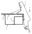
- hollow profiled auxiliary strut 8 instead of in 1 to 4 hollow profiled auxiliary strut 8 also shown right-angled longitudinal profile or a similar open profiled auxiliary strut can be used, as indicated in Fig. 5.
- the connection takes place preferably by an adhesive seam between surface sections the structural element of plastic 3 and the connecting surfaces 24, 25 of the metallic cross brace 2. Alternatively, the Connection can also be made by several screws, rivets or flanged edges.
- the structural element of plastic 3 is substantially planar along the main direction of the hybrid crossbeam 1. At the ends of the Structural element made of plastic 3 are angled mounting straps 31 and 32 are provided with which the hybrid cross member 1 to the so-called A-pillar of a vehicle body is fastened.
- the Plastic structural element 3 advantageous near its left and right end respectively via an opening 33, 34, which the passage the air ducts from the interior of the hybrid cross member 1 in the area allow the instrument panel of the vehicle.
- the structural element made of plastic 3 has a recess for receiving the Steering column connection 5 on.
- the steering column connection 5 is made of a solid Material, preferably made of metal. In particular, this can a die-cast aluminum alloy are used.
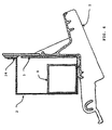
- the steering column connection 5 has attachment points 51 for attachment in the Drawings not reproduced.Lenkwellenlagerü on. A special compact and space-saving construction results when in the area the steering column connection, the lower connection surface 25 on the metallic Cross strut 2 is interrupted, as this particular from the Sectional views in Figs.
- a particularly stable Connection between steering column connection 5, and the metallic cross strut 2 is obtained when the upper connecting surface 24 of the metallic Cross strut 2 equipped with fastening eyes 26 and with an upper Section of the steering column connection 5 by screws or rivets 52 are.
- a particularly stable connection between the steering column connection 5 and the auxiliary strut 8 is obtained when these components in a lower Area of the steering column connection 5 with screws 81 and spacers against each other are curious, as indicated in Fig. 3.
- the connection between the metallic cross member 2 and the Fastening tab 4 done by screws 41 as is also out Fig. 3 shows.
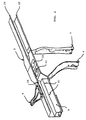
- a fastening tab 4 is arranged above the steering column connection 5 in the metallic cross member. 2 according to Fig. 1 and Fig. 3, a fastening tab 4 is arranged.
- the between the hybrid crossbeam 1 and the frame of the windshield remaining gap should be as large as possible so that in the event of a frontal impact of the vehicle to the meeting of hybrid crossbeam 1 and Frame of the windshield required deformation of the vehicle body is as large as possible and thus held on the hybrid cross member 1 Steering column connection 5 together with the not reproduced steering wheel pushed as far as possible into the passenger compartment in this case becomes.
- the fastening tab is preferably made of metal be, in particular, offers a pressed sheet metal part. If appropriate Material choice can be the connection between the metallic Cross strut 2 and the fastening tab 4 by welding, in particular Spot welding done. Otherwise, the connection may be by riveting or gluing done.
- frequency struts 6 and 7. are intended to the hybrid cross member 1 in the region of its center opposite to fix the vehicle body in the vertical direction and thereby especially to suppress the first natural vibration of the hybrid cross member 1. Between the frequency struts 6, 7 remains a space for Recording of air conditioner, radio receiver and the like.
- the openings 22, 23 at the bottom of the metallic cross member 2 allow In this case, the passage of the air ducts from the air conditioner in the hybrid cross member 1 in, from where the air ducts to the left and right up to the lateral outlet openings 33, 34 in the structural element continue in plastic 3, in the area of the left and right End out of the interior of the hybrid cross member 1 and emerge go into the air outlets in the instrument panel.
- the auxiliary strut hits 8 in a particularly preferred embodiment with their right or inner end to the upper end of the frequency strut 6 together. Thereby are acting vertically on the steering column connection 5 forces less in the metallic cross brace 2 introduced, but mainly from the Auxiliary strut 8 between the lateral body connection 31 left and split the frequency strut 6.
- the described hybrid cross member 1 is particularly cost-effective Type obtained when the metallic cross brace 2 made of a pressed Steel or aluminum sheet is made.
- the frequency struts are useful 6, 7 and the fastening tab 5 made of the same material manufactured and welded to the metallic cross strut 2, riveted or glued.
- the auxiliary strut 8 on the driver's side preferably glued into the metallic cross member 2, with an on any previous welding or spot welding of the above Arrangement of metallic transverse strut 2, frequency struts 6, 7 and fastening tab 5 declining distortion of the metallic cross member 2 usually does not exceed the permissible glue gap lead, so refrain from straightening after welding can.
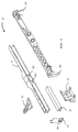
- a third hybrid cross member 1 'for installation in a left-hand drive vehicle includes according to FIGS. 6 and 7, first a cross member with a Main strut 2 '.
- the main strut 2 ' is preferably made of a metallic Material manufactured, e.g. made of pressed steel or aluminum sheet.
- the main strut 2 'further extends substantially along the direction of the main extension of the cross member 1 ', the hereinafter referred to as its main direction.
- the shape of the Main strut 2 ' is apparent in particular from Fig. 6, which is an exploded view of the third hybrid cross member 1 'shows.
- the main strut 2 ' Almost perpendicular to the main direction of the third hybrid cross member 1 ' the main strut 2 'has a substantially U-shaped cross-section on, wherein dimensions and shape of the cross section along the main direction vary.
- the to Vehicle interior facing edges of the main strut 2 ' are preferably over the entire length advantageously bent outward to two elongated narrow connecting surfaces 24 ', 25' for connecting the Main strut 2 with the structural element made of plastic 3 'to obtain.
- a first section near the right end of the cross member is the U-shaped profile of the main strut 2 'comparatively flat and narrow trained.
- the width of the U-shaped profile runs however, approximately in a vertical with respect to the vehicle Direction.
- a second section in the middle third section of the third hybrid cross member 1 ' is the U-shaped profile of the main strut 2 'almost as narrow as in the section described above, however much deeper trained than there. In this way is within the carrier space for further air ducts and air entrances available.
- a third section on the driver's side takes the depth of the U-shaped profile again and reaches approximately the depth of the profile in the right section.
- Tunnel supports 6 'and 7' arranged in a central region of the main strut 2 'below. These lay the third hybrid crossbeam 1 'in the region of its center opposite the vehicle body in vertical Direction firm and suppress thereby above all its first Self-oscillation. Between the tunnel supports 6 ', 7' remains a space for receiving air conditioner, radio receiver and the like.
- auxiliary strut 8 ' is below the main strut 2 'to this adjacent the auxiliary strut 8 'arranged.
- this will Auxiliary strut 8 'from a section of an extrusion, a rectangular tube or the like.
- the auxiliary strut 8 ' is with the Main strut 2 'in the area of the adjacent surfaces expediently at least connected pointwise or in sections.
- This compound may be suitable Choice of material for example by welding, in particular spot welding respectively.
- the connection can also be made by riveting, Screwing or gluing done. The latter options are considered special to look favorably because their application is expected only a slight delay or even practical in the case of the adhesive bond will not cause any distortion on the components.
- auxiliary strut 8 torsionally rigid with the left tunnel support 6' connected.
- This connection is expediently carried out by positive interlocking certain intended sections on the auxiliary strut 8 'and the upper end of the left tunnel support 6'.
- This upper one Section of the tunnel support 6 ' may also be in addition to the main strut 2 'be connected to linear forces in the vertical direction in the Main strut 2 'and the third hybrid cross member 1' in total to give optimum rigidity.
- auxiliary strut 8 ' is based on the largest in the Use expected by the steering column connection 5 'on the cross member impressed linear and torsional forces.
- hollow profiled auxiliary strut 8 'shown in FIGS. 6 to 8 also a right-angled longitudinal profile or a similar profiled open Assist strut can be used.
- connection of the hybrid crossbeam with the A-pillars of the vehicle body takes place on the left and right ends via mounting brackets, of which in Fig. 6 only provided for the driver-side connection mounting bracket 9 'is shown.
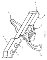
- This driver side mounting bracket has a Section for positive connection with the auxiliary strut 8 'on.
- This positive connection can as shown in Figs. 6 and 8 through a rectangular opening 91 'in the mounting bracket 9', in which one end of the auxiliary strut 8 'is received.
- connection is preferably made by an adhesive seam between surface portions of the structural element 3 'and the Connecting surfaces 24 ', 25'.
- connection can also be through several screws, rivets or flanged edges.
- the structural element 3 ' extends substantially flat along the Main direction of the third hybrid crossmember.
- the Structural element 3 ' are angled fastening tabs 31' and 32 ' provided, with which the hybrid cross member 1 'to the so-called A-pillars a vehicle body is fastened.
- the structural element has 3 'advantageously near the left and right ends, respectively through openings 33 ', 34' the passage of air from the interior of the cross member in the area of the instrument panel of the vehicle allow. Further openings 35 ', 36' may be in the area of the center of Structure element 3 'may be provided.
- the steering column connection 5 ' is made of a solid material, preferably made of metal. In particular, this can be a die-cast aluminum alloy come into use.
- the steering column connection 5 ' has Attachment points 51 'for attaching a not in the drawings reproduced steering shaft bearing unit.
- a particularly stable connection between steering column connection 5 ', and the main strut 2' is obtained when the upper connecting surface 24 of the main strut 2 'according to Fig. 7 equipped with fastening eyes 26 'and with an upper portion the steering column connection 5 'connected by screws or rivets is.
- a particularly stable connection between the steering column connection 5 'and the auxiliary strut 8' is also obtained when these components in a lower portion of the steering column connection 5 'with screws and spacers are curious against each other.
- a fastening tab 4 ' is on the main strut 2' shown in FIG. 6 and Fig. 8, a fastening tab 4 'arranged.
- the between the cross member and the The windshield remaining gap should be as large as possible so that in the event of a frontal collision of the vehicle to coincide required by cross member and frame of the windshield Deformation of the vehicle body is as large as possible and consequently the on the hybrid cross member 1 'held steering column connection 5' together with the Steering wheel in this case to the least possible extent in the passenger compartment is shifted into it.
- the fastening tab 4 ' is preferably made Be made metal, in particular, offers a pressed sheet metal part at.
- the connection between the Main strut 2 'and the fastening tab 4' by welding, in particular Spot welding done. Otherwise, the connection may be by riveting or gluing done.
- vertically acting on the steering column connection 5 ' Forces introduced less in the main strut 2 ', but mainly by the auxiliary strut 8 'between the left, side body connection Divided 9 'and the driver side tunnel support 6'.
- the described third hybrid cross member 1 ' is particularly inexpensive Type obtained when the main strut 2 'from a pressed Steel or aluminum sheet is made.
- Appropriate are the tunnel supports 6 ', 7' and the fastening tab 5 'made of the same material. This leaves a welding of these parts with the main strut 2 ' to.
- the auxiliary strut 8 'on the driver's side is with the Bottom of the main strut 2 'preferably glued, with one on one possibly previous welding or spot welding of the above Arrangement of main strut 2 ', tunnel supports 6', 7 'and fastening strap 5 'declining delay of the main strut 2' usually not too will exceed the permissible glue gap. Set up after welding, in most cases, should be dispensable. One Straightening is not done for the same reasons even before joining and Gluing the entire created in the above steps Arrangement of main strut 2 ', tunnel supports 6', 7 ', auxiliary strut 8' and Fastening tab 4 'with the structural element of plastic 3' necessary be.
- the permissible tolerances for the adhesive gap the possibly occurring during welding delay in the Usually record In a final step, the steering column connection 5 'with the respective sections of the auxiliary strut 8', the Main strut 2 'and the structural element of plastic 3' preferably connected by several screws.
Landscapes
- Engineering & Computer Science (AREA)
- Chemical & Material Sciences (AREA)
- Combustion & Propulsion (AREA)
- Transportation (AREA)
- Mechanical Engineering (AREA)
- Architecture (AREA)
- Structural Engineering (AREA)
- Body Structure For Vehicles (AREA)
Abstract
Description
- Fig. 1
- eine perspektivische Ansicht eines ersten Hybridquerträgers schräg von vorne rechts;
- Fig. 2
- eine perspektivische Ansicht einer ersten Teilstruktur des Hybridquerträgers gemäß Fig. 1 schräg von links;
- Fig. 3
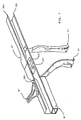
- eine perspektivische Ansicht eines Ausschnitts aus einer weiteren Teilstruktur eines Hybridquerträgers gemäß Fig. 1;
- Fig. 4
- eine Schnittansicht entlang einer vertikalen Schnittebene im Bereich der Lenkstockanbindung durch den Hybridquerträger gemäß Fig. 1;
- Fig. 5
- eine Schnittansicht entlang einer vertikalen Schnittebene im Bereich der Lenkstockanbindung durch einen zweiten Hybridquerträger;
- Fig. 6
- eine perspektivische Explosionsansicht eines dritten Querträgers;
- Fig. 7
- eine perspektivische Ansicht einer Teilstruktur des Querträgers gemäß Fig. 6; und
- Fig. 8
- eine perspektivische Ansicht auf einen Abschnitt der Rückseite des Querträgers gemäß Fig. 6 von unten.
Claims (14)
- Hybridquerträger (1) für ein Fahrzeug, aufweisend eine metallische Querstrebe (2) mit einem in Richtung der Hauptrichtung des Hybridquerträgers (1) in der Form einer offenen Rinne verlaufenden Abschnitt, dessen Längskanten (21, 22) mit einem Strukturelement aus Kunststoff (3) in einem Abschnitt verbunden sind.
- Hybridquerträger nach Anspruch 1, wobei die Verbindung zwischen der metallischen Querstrebe (2) und dem Strukturelement aus Kunststoff (3) eine Klebeverbindung ist.
- Hybridquerträger nach Anspruch 2, wobei die Querstrebe (2) im wesentlichen entlang ihrer gesamten Längserstreckung rinnenförmig und mit dem Strukturelement (3) verklebt ist.
- Hybridquerträger einem der vorangehenden Ansprüche, wobei der Raumbereich innerhalb des rinnenförmigen Abschnitts der metallische Querstrebe (2) ausgehend von der Mitte des Hybridquerträgers (1) bis zu dessen linken und rechten Ende jeweils einen offen und einen durchgehenden Kanal zur Aufnahme einer Luftführung aufweist.
- Querträger für ein Fahrzeug, aufweisend eine Hauptstrebe (2') mit einem in Richtung der Hauptrichtung des Querträgers (1') in der Form einer offenen Rinne verlaufenden Abschnitt, eine dazu benachbart angeordnete Hilfsstrebe (8), eine Tunnelstütze (6') und eine Lenkstockanbindung (5'), wobei die Hilfsstrebe (8') mit der Tunnelstütze (6') und der Lenkstockanbindung (5') drehsteif verbunden ist.
- Querträger für ein Fahrzeug nach Anspruch 5, wobei Mittel (9') zum drehsteifen Verbinden der Hilfsstrebe (8') im Bereich des äußeren Endes der Hauptstrebe (2') mit einer Stelle einer Kraftfahrzeugkarosse vorgesehen sind.
- Querträger für ein Fahrzeug nach einem der Ansprüche 5 und 6, wobei die Hilfsstrebe (8') unterhalb der Hauptstrebe (2') angeordnet ist.
- Querträger für ein Fahrzeug nach Anspruch 7, wobei die Oberseite der Hilfsstrebe (8') mit der Unterseite der Hauptstrebe (2') verklebt ist.
- Querträger für ein Fahrzeug nach einem der Ansprüche 5 bis 8, wobei die Hilfsstrebe (8') ein Quadratrohr ein Rechteckrohr oder ein Abschnitt eines Strangpressprofils ist.
- Querträger für ein Fahrzeug nach einem der Ansprüche 5 bis 9, wobei die Hauptstrebe (2') ein rinnenförmiges Profil aufweist, innerhalb dessen Luftführungen angeordnet sind.
- Querträger nach einem der vorangehenden Ansprüche, wobei die Hauptstrebe (2') aus Metall ist.
- Querträger für ein Fahrzeug nach Anspruch 11, wobei die Hauptstrebe (2') aus Metallblech, insbesondere aus Stahlblech oder Aluminiumblech gepresst ist.
- Hybridquerträger (1'), aufweisend einen Querträger nach einem der Ansprüche 5 bis 12 und ein Strukturelement (3'), wobei das Strukturelement mit der Hauptstrebe (2') abschnittsweise verklebt ist.
- Hybridquerträger (1') nach Anspruch 13, wobei das Strukturelement (3') aus Kunststoffmaterial, insbesondere aus einem glasfaserverstärkten Kunststoffmaterial spritzgegossen ist.
Applications Claiming Priority (4)
| Application Number | Priority Date | Filing Date | Title |
|---|---|---|---|
| DE2003160045 DE10360045A1 (de) | 2003-12-18 | 2003-12-18 | Hybridquerträger |
| DE10360045 | 2003-12-18 | ||
| DE200410016533 DE102004016533A1 (de) | 2003-12-18 | 2004-03-31 | Querträger |
| DE102004016533 | 2004-03-31 |
Publications (2)
| Publication Number | Publication Date |
|---|---|
| EP1544085A2 true EP1544085A2 (de) | 2005-06-22 |
| EP1544085A3 EP1544085A3 (de) | 2006-02-08 |
Family
ID=34524087
Family Applications (1)
| Application Number | Title | Priority Date | Filing Date |
|---|---|---|---|
| EP04029800A Withdrawn EP1544085A3 (de) | 2003-12-18 | 2004-12-15 | Querträger eines Fahrzeugs, insbesondere Hybridquerträger |
Country Status (2)
| Country | Link |
|---|---|
| EP (1) | EP1544085A3 (de) |
| DE (1) | DE102004016533A1 (de) |
Cited By (11)
| Publication number | Priority date | Publication date | Assignee | Title |
|---|---|---|---|---|
| FR2883543A1 (fr) * | 2005-04-07 | 2006-09-29 | Faurecia Interieur Ind Snc | Structure de vehicule automobile et vehicule automobile correspondant. |
| DE102007051708A1 (de) * | 2007-10-30 | 2009-05-07 | Dr. Ing. H.C. F. Porsche Aktiengesellschaft | Abstützeinrichtung |
| DE102007050776B4 (de) * | 2007-10-24 | 2011-07-14 | Kirchhoff Automotive GmbH & Co. KG, 57439 | Bauteil für Kraftfahrzeuge |
| CN102673660A (zh) * | 2011-03-10 | 2012-09-19 | 通用汽车环球科技运作有限责任公司 | 车用板组件和连接车用板组件的方法 |
| FR3029490A1 (fr) * | 2014-12-03 | 2016-06-10 | Renault Sa | Element de structure de la partie avant d'un vehicule |
| EP3279063A1 (de) | 2016-08-05 | 2018-02-07 | Magna Steyr Fahrzeugtechnik AG & Co KG | Querträger und cockpit-modul |
| CN108238112A (zh) * | 2016-12-27 | 2018-07-03 | 五十铃自动车株式会社 | 车辆 |
| CN112937694A (zh) * | 2016-06-01 | 2021-06-11 | 现代自动车株式会社 | 用于车辆的前围板横杆 |
| WO2022156006A1 (zh) * | 2021-01-20 | 2022-07-28 | 万丰镁瑞丁新材料科技有限公司 | 一种组合式汽车仪表盘支架 |
| CN117203117A (zh) * | 2021-04-30 | 2023-12-08 | 奇昊汽车德国有限责任公司 | 用于机动车的仪表板支架 |
| US20250229841A1 (en) * | 2024-01-16 | 2025-07-17 | Ford Global Technologies, Llc | Cross car beam |
Family Cites Families (5)
| Publication number | Priority date | Publication date | Assignee | Title |
|---|---|---|---|---|
| DE20008201U1 (de) * | 2000-05-08 | 2000-07-27 | Benteler Ag, 33104 Paderborn | Instrumententafelträger |
| FR2834270B1 (fr) * | 2001-12-27 | 2004-06-18 | Sai Automotive Allibert Ind | Ensemble structurel pour planche de bord |
| US6644722B2 (en) * | 2002-01-17 | 2003-11-11 | Bayer Corporation | Molded article having a rigid support and a rigid hollow member |
| EP1350711B1 (de) * | 2002-03-27 | 2006-08-02 | DENSO THERMAL SYSTEMS S.p.A. | Träger in gemischter Bauweise für das Armaturenbrett eines Kraftfahrzeugs und dessen Herstellungsverfahren |
| DE10220025A1 (de) * | 2002-05-04 | 2003-11-20 | Behr Gmbh & Co | Querträger |
-
2004
- 2004-03-31 DE DE200410016533 patent/DE102004016533A1/de not_active Withdrawn
- 2004-12-15 EP EP04029800A patent/EP1544085A3/de not_active Withdrawn
Cited By (16)
| Publication number | Priority date | Publication date | Assignee | Title |
|---|---|---|---|---|
| FR2883543A1 (fr) * | 2005-04-07 | 2006-09-29 | Faurecia Interieur Ind Snc | Structure de vehicule automobile et vehicule automobile correspondant. |
| DE102007050776B4 (de) * | 2007-10-24 | 2011-07-14 | Kirchhoff Automotive GmbH & Co. KG, 57439 | Bauteil für Kraftfahrzeuge |
| DE102007051708A1 (de) * | 2007-10-30 | 2009-05-07 | Dr. Ing. H.C. F. Porsche Aktiengesellschaft | Abstützeinrichtung |
| US7661745B2 (en) | 2007-10-30 | 2010-02-16 | Dr. Ing. H.C. F. Porsche Aktiengesellschaft | Supporting device |
| DE102007051708B4 (de) | 2007-10-30 | 2024-02-08 | Dr. Ing. H.C. F. Porsche Aktiengesellschaft | Abstützeinrichtung und Kraftfahrzeug |
| CN102673660A (zh) * | 2011-03-10 | 2012-09-19 | 通用汽车环球科技运作有限责任公司 | 车用板组件和连接车用板组件的方法 |
| CN102673660B (zh) * | 2011-03-10 | 2015-09-02 | 通用汽车环球科技运作有限责任公司 | 车用板组件和连接车用板组件的方法 |
| FR3029490A1 (fr) * | 2014-12-03 | 2016-06-10 | Renault Sa | Element de structure de la partie avant d'un vehicule |
| CN112937694B (zh) * | 2016-06-01 | 2023-05-09 | 现代自动车株式会社 | 用于车辆的前围板横杆 |
| CN112937694A (zh) * | 2016-06-01 | 2021-06-11 | 现代自动车株式会社 | 用于车辆的前围板横杆 |
| DE102016214579A1 (de) | 2016-08-05 | 2018-02-08 | Magna Steyr Fahrzeugtechnik Ag & Co Kg | Querträger und Cockpit-Modul |
| EP3279063A1 (de) | 2016-08-05 | 2018-02-07 | Magna Steyr Fahrzeugtechnik AG & Co KG | Querträger und cockpit-modul |
| CN108238112A (zh) * | 2016-12-27 | 2018-07-03 | 五十铃自动车株式会社 | 车辆 |
| WO2022156006A1 (zh) * | 2021-01-20 | 2022-07-28 | 万丰镁瑞丁新材料科技有限公司 | 一种组合式汽车仪表盘支架 |
| CN117203117A (zh) * | 2021-04-30 | 2023-12-08 | 奇昊汽车德国有限责任公司 | 用于机动车的仪表板支架 |
| US20250229841A1 (en) * | 2024-01-16 | 2025-07-17 | Ford Global Technologies, Llc | Cross car beam |
Also Published As
| Publication number | Publication date |
|---|---|
| DE102004016533A1 (de) | 2005-10-27 |
| EP1544085A3 (de) | 2006-02-08 |
Similar Documents
| Publication | Publication Date | Title |
|---|---|---|
| DE102007006722C5 (de) | Träger für eine Karosserie eines Kraftwagens | |
| EP0941912B1 (de) | Kraftfahrzeug mit einem flächigen Versteifungselement | |
| DE10040824B4 (de) | Lenksäulen-Tragbalkenstruktur | |
| EP1829767B1 (de) | Hilfsrahmen zur Befestigung an einer Karosserie eines Kraftwagens | |
| DE19533366C2 (de) | Aufprallträger für Kraftfahrzeuge | |
| DE19830303B4 (de) | Anordnung eines Instrumententafelträgers in einer Fahrzeugkarosserie und Instrumententafelträger | |
| DE19812701B4 (de) | Karosseriestruktur für den Frontbereich eines Kraftfahrzeuges | |
| EP2038164B1 (de) | Abstützelement für einen cockpitträger | |
| EP0861767A1 (de) | Schweller eines Kraftfahrzeugs mit einer Verstärkungseinlage | |
| DE19603954C2 (de) | Prallträger für ein Kraftfahrzeug | |
| DE10058113B4 (de) | Hilfsrahmenmodul | |
| DE19824638A1 (de) | Fahrzeug-Rahmen-Aufbau | |
| EP2040970A1 (de) | Anordnung zur befestigung einer lenksäule eines kraftfahrzeuges | |
| DE102004050435A1 (de) | Stoßfängersystem für Kraftfahrzeug | |
| DE102004016533A1 (de) | Querträger | |
| EP2030869B1 (de) | Träger als Längs- bzw. Querträger in einem Kraftfahrzeug | |
| EP2374666A2 (de) | Verbindungsanordnung von wenigstens zwei Strukturbauteilen für einen Kraftwagen sowie Verfahren zu deren Herstellung | |
| DE102007032481A1 (de) | Fahrzeugaufbau | |
| DE102006009290B4 (de) | Tragstruktur für ein Frontend eines Kraftwagens | |
| DE10032663B4 (de) | Kraftwagen mit einer selbsttragenden Karosserie | |
| DE10360045A1 (de) | Hybridquerträger | |
| WO2009077069A1 (de) | Seitentür für einen kraftwagen | |
| DE29622715U1 (de) | Prallträger für ein Kraftfahrzeug | |
| EP1717130A1 (de) | Instrumententafelträgerstruktur | |
| DE19906447B4 (de) | Gehäuse zur Aufnahme eines gefalteten Luftsacks |
Legal Events
| Date | Code | Title | Description |
|---|---|---|---|
| PUAI | Public reference made under article 153(3) epc to a published international application that has entered the european phase |
Free format text: ORIGINAL CODE: 0009012 |
|
| AK | Designated contracting states |
Kind code of ref document: A2 Designated state(s): AT BE BG CH CY CZ DE DK EE ES FI FR GB GR HU IE IS IT LI LT LU MC NL PL PT RO SE SI SK TR |
|
| AX | Request for extension of the european patent |
Extension state: AL BA HR LV MK YU |
|
| PUAL | Search report despatched |
Free format text: ORIGINAL CODE: 0009013 |
|
| AK | Designated contracting states |
Kind code of ref document: A3 Designated state(s): AT BE BG CH CY CZ DE DK EE ES FI FR GB GR HU IE IS IT LI LT LU MC NL PL PT RO SE SI SK TR |
|
| AX | Request for extension of the european patent |
Extension state: AL BA HR LV MK YU |
|
| AKX | Designation fees paid |
Designated state(s): AT BE BG CH CY CZ DE DK EE ES FI FR GB GR HU IE IS IT LI LT LU MC NL PL PT RO SE SI SK TR |
|
| STAA | Information on the status of an ep patent application or granted ep patent |
Free format text: STATUS: THE APPLICATION IS DEEMED TO BE WITHDRAWN |
|
| 18D | Application deemed to be withdrawn |
Effective date: 20060809 |