EP1543893A1 - Procédé pour soyer un profilé et profilé soyé selon ce procédé - Google Patents
Procédé pour soyer un profilé et profilé soyé selon ce procédé Download PDFInfo
- Publication number
- EP1543893A1 EP1543893A1 EP04300911A EP04300911A EP1543893A1 EP 1543893 A1 EP1543893 A1 EP 1543893A1 EP 04300911 A EP04300911 A EP 04300911A EP 04300911 A EP04300911 A EP 04300911A EP 1543893 A1 EP1543893 A1 EP 1543893A1
- Authority
- EP
- European Patent Office
- Prior art keywords
- wing
- thickness
- profile
- slope
- segment
- Prior art date
- Legal status (The legal status is an assumption and is not a legal conclusion. Google has not performed a legal analysis and makes no representation as to the accuracy of the status listed.)
- Granted
Links
- 238000000034 method Methods 0.000 title claims abstract description 19
- 238000009966 trimming Methods 0.000 claims description 13
- 239000000463 material Substances 0.000 description 5
- 230000002787 reinforcement Effects 0.000 description 2
- 230000003014 reinforcing effect Effects 0.000 description 2
- 238000009331 sowing Methods 0.000 description 2
- 239000011324 bead Substances 0.000 description 1
- 230000000903 blocking effect Effects 0.000 description 1
- 230000003247 decreasing effect Effects 0.000 description 1
- 230000006866 deterioration Effects 0.000 description 1
- 238000006073 displacement reaction Methods 0.000 description 1
- 238000009432 framing Methods 0.000 description 1
- 238000005728 strengthening Methods 0.000 description 1
Images

Classifications
-
- B—PERFORMING OPERATIONS; TRANSPORTING
- B21—MECHANICAL METAL-WORKING WITHOUT ESSENTIALLY REMOVING MATERIAL; PUNCHING METAL
- B21D—WORKING OR PROCESSING OF SHEET METAL OR METAL TUBES, RODS OR PROFILES WITHOUT ESSENTIALLY REMOVING MATERIAL; PUNCHING METAL
- B21D11/00—Bending not restricted to forms of material mentioned in only one of groups B21D5/00, B21D7/00, B21D9/00; Bending not provided for in groups B21D5/00 - B21D9/00; Twisting
- B21D11/18—Joggling
Definitions
- the invention relates to a method for forming a profile and a profile used according to this method.
- To use a profile is to deform such a profile of way to create a gap between two of its parts.
- the profile to soyer is a beam of any section having in its profile a mast and wings at both ends of it mast.
- the purpose of the invention is to reduce a length in the offset conferred by a soy.
- the present invention finds an application particularly advantageous, but not exclusive, in the field of aeronautics.
- a bent profile is used to strengthen a connection between two pieces, such as two parts of an airplane, that are not aligned one with respect to the other.
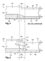
- FIG. 1 shows a view of a profile 100 of the state of the technical.
- This profile here has an I-shaped section but could have any section, such as a C or U section.
- profile 100 comprises a first and a second wing 101 and 102 and a mast 103.
- the first wing 101 is of great thickness E1 and the second wing 102 is of small thickness E2.
- This profile 100 is used for providing or reinforcing a connection between a part 121 and a part 122.
- the first wing 101 and the second wing 102 unfurl each in a plane which forms a non-zero angle with a plane of the mast 103, itself located in the plane of Figure 1.
- these wings 101 and 102 each unfurl in a plane that is perpendicular to a mast plane 103.
- a linkage 104 is present between a first part 105 and a second part 106 of the profile. This sorting 104 corresponds at the part of the profile 100 which is deformed. This sorting 104 provides a between the first part 105 and the second part 106.
- the offset extends in the plane of the mast 103 of the profile with a height H of offset measured in a direction perpendicular to the plane of the wings 101 and 102, and with an offset length L measured in one direction parallel to the plans of the mast 103 and wings 101 and 102.
- This length L is calculated according to a thickness of a wing.
- the length L is globally equal to six times the thickness of a wing. This relationship between the thickness of a wing and the length L varies depending on the material in which the profile is made. Length L is as short as possible but can not be reduced as much as desired. Indeed, the proportion of six times the thickness of the wing is a constraint that can not be transgressed without risk of deterioration of the profile.
- the length L is calculated from the thickness of the larger of the two wings. In Figure 1, the length L is therefore equal to six times the thickness E1 of the wing 101 of great thickness. In its trimming 104, the profile 100 therefore has identical slopes on both sides wings 103 and 104
- the used section 100 is used to reinforce a connection between two parts 121 and 122 having a difference in level.
- a space 130 depending on the length L is observable between the pieces 121 and 122 and the 100.
- the space 130 between the parts and the profile is important. AT the place of such a space 130, the profiles soys of the state of the art do not therefore not optimally involved in strengthening the link between rooms 121 and 122.
- the invention aims to solve this problem of space 130 too between the profile 100 and the parts 121 and 122.
- the invention implements, in particular, a profiled section with offset lengths calculated according to each thicknesses of the profile.
- the length of the offset provided by the side of the wing of great thickness is greater than the length of the offset provided by the squelching of the side of the thin wing. In the invention, these lengths are no longer identical.
- the sinking of the seam profile according to the invention comprises a geometry particular in which ends of the carousel forms a quadrilateral looking like a trapeze unlike near slopes. In this quadrilateral, no side is parallel to another. Projections end of the searing on the side of the thin wing are preferably located inside projections of ends of the squelch of the side of the wing of great thickness.
- the thin wing on two pieces non-aligned links between them is to strengthen.
- the length of the offset provided by the squelch of the side of the thin wing is equal to N times the length of the small thickness; whereas this length would have been equal to N times the length of the great thickness using a state of the art trimming method.
- N is in an example equal to six but varies depending on the nature of the material in which the profile is made.
- a method is implemented in which is pressed with a punch on a profile wedged between this punch and an anvil.
- a punch is made which comprises a part with a shallow gradient extending over a length proportional to the thickness of the wing of great thickness.
- an anvil that has a steeply sloping portion length which is proportional to a thickness of the wing of small thickness. The anvil is fixed. The punch is mobile.
- the side of the profile with the thin wing is placed against the anvil.
- the punch is placed against the side of the profile including the large wing thickness.
- the placement of the punch is realized in such a way that projections of ends of the part of the anvil presenting a slope in the opposite direction of a support, are located between projections of ends of the part of the punch having a slope in the direction of support. In particular achievements, some projections may to be confused with each other.
- the punch is then pressed so that the profile is compressed between the punch and the anvil.
- the shapes printed by this punch and this anvil on one side and the other of the profiling of the profile are different.
- the punch comprises a segment of steep slope and the anvil has a low slope segment.
- FIG. 2 shows the profiled section 200 according to the invention comprising as in Figure 1, the mast 103, the first wing 101 of great thickness E1 and the second wing 102 of great thickness E2.
- This profiled 200 soyé plays a role of connection between the parts 111 and 110, such as parts of a plane.
- the linking seam 201 provides a gap between the first part 105 and the second portion 106 of the profile 200. This offset exists in relation to to a plane P of alignment between these two parts. This shift extends into the plane of the mast of the profile with a height H measured in one direction perpendicular to the plane of the wings and with a measured length L1 or L2 in a direction parallel to the plans of the mast and wings.
- the height H of the offset of the side of the wing of great thickness and that of the side of the wing of small thickness are identical.
- length L1 of the offset of the wing 101 of thick thickness is more large as the L2 length of the wing offset 102 of low thickness.
- the section 200 has a low slope, in the sinking 201, the side of the wing 101 of great thickness, and a steep slope, in the trimming 201, the side of the wing 102 of small thickness.
- the length L1 is proportional to the thickness E1 of the wing 101 and the length L2 is proportional to a thickness E2 of the wing 102.
- the lengths L1 and L2 are respectively equal to six times the great thickness E1 and to six times the small E2 thickness.
- this ratio varies depending on the nature of the material in which the profile 200 is made. So, the 201 grinding of slope strong side wing 102 thin, spread between the two parts 105 and 106, over a length L2 equal to six times the thickness of this wing of thin.
- the low slope 201 trimming on the wing side of large thickness is spread between the two parts 105 and 106, over an equal length at six times the thickness of this wing of great thickness.
- the relationship between lengths L1 and L2 and the thicknesses E1 and E2 can vary in a range real values between four and ten.
- projections end of the linkage 201, on the side of the steep slope are located between end projections of the linkage 201, on the side of the low slope.
- the ends of the squelch 201 on the side of the wing 102 thin are projected in one direction perpendicular to the wings 101 and 102, and in a direction from the small wing 102 to the main wing 101.
- the projections of these ends are located between projections of ends of the sear 201 on the side of the wing 101 of large thickness, in the direction perpendicular to the wings 101 and 102, and in a reverse direction from the large wing 101 to the small wing 102.
- a projection of one end of the 201, on the side of the steep slope, according to the direction and meaning mentioned above, is confused with a projection of one end of the srive, on the side of the low slope, in the opposite direction and opposite direction.
- These projections may result in the highlighting of a distance P1 and a distance P2.
- the distance P1 which extends into a direction parallel to the planes of the mast 103 and the wings 101 and 102, separates opposite ends of the seam 201.
- a distance P2 which extends into the direction parallel to the plane of the mast 103 and the wings 101 and 102, separates other opposite ends of the seam 201. In general, these distances P1 and P2 are different.
- the distance D1 or the distance D2 is zero. This realization is represented in discontinuous lines on the figure.
- the soyage 201 thus comprises a completely different geometry that of the trimming 104 of the section of FIG. 1. Indeed, the ends of the 210 form a quadrilateral 210, in which, unlike a quadrilateral associated with the sear 104, no side is parallel to another.
- the geometry of the jogging 201 is determined according to a congestion, a geometry of an external system, or stops surrounding the profile 300. This geometry can also be determined by compared to a mechanical reinforcement indicated in a specification.
- the space 130 between the profile 200 and the parts 121 and 122 is decreased to meet the requirements of an office studies. In one example, this decrease in space makes it possible to satisfy to constraints related to rigidity of assembly or resistance between parts 110 and 111.
- FIG. 3 shows steps of a jogging method allowing make the profiled section of Figure 2. It implements this method on a 300 straight profile comprising the wings 101 and 102 of great thickness and small thickness.
- a fixed anvil 301 is produced. having a segment 302 of steep slope which is spread between two parts 303 and 304 parallels along the length L2. This length L2 is proportional to a thickness E2 of the wing 102 of small thickness.
- This length L1 is proportional to a thickness of the wing 101 of great thickness.
- the lengths L1 and L2 of segments 302 and 312 of steep slope and slope low are respectively equal to N times the thickness of the wing 101 large thickness and N times the thickness of the wing 102 of small thickness.
- N is a real number which in an example is equal to 6. However, N varies depending of the nature of the material in which the profile 300 is made.
- FIG. 3a shows a step in which the wing 102 of small thickness of the profile 300 against the anvil 301. Then place the punch 311 against the wing 101 of great thickness of the profile 300.
- the ends of the slope segment 302 are placed strong so that projections of the ends of the segment of steep slope 302 in the opposite direction of a support, either located between projections in the direction of bearing the ends of the slope segment 312 low.
- the punch 311 is then in an initial position.
- a end of the slope segment 312 weak so that the projection this end is confused with a projection of one end of the sharp slope segment 302.
- a distance P1 is observed between one end of segment 302 of steep slope and one end of segment 312 of low slope.
- a distance P2 between another end of the slope segment 302 strong and another end of segment 312 of low slope. These distances are observed in a direction parallel to the plane of the mast 103 and wings 101 and 102. The length of these distances P1 and P2 can be adjusted thanks to the arrangement of holds 321 and 322.
- the holds 321 and 322 and the anvil 301 are fixed and are interconnected by the intermediate parts 330 can be integral with a frame.
- Figure 3b shows a step in which the punch is pressed 311, so that this punch 311 and the anvil 301 print their shape at 300.
- one removes the wedge 321 laterally and one exerts pressure forces on the punch 311.
- These pressure forces F1 are applied in a direction perpendicular to the plane of the wings 101 and 102 and in a direction going from wing 101 of great thickness towards wing 102 of small thickness.
- the shim 321 is not removed and the anvil slides between the two holds 321 and 322. More precisely, in this variant, the shim 322 does not move laterally to release the punch.
- the punch 311 then has a degree of freedom allowing it to slide between the shims 321 and 322.
- the shims 321 and 322 retain the punch 311 only during the time of its placement then allow its displacement during the support.
- F1 forces are applied locally in an area of segments 302 and 312 of slopes. Alternatively, these F1 forces are no only applied in the area of the 302 and 312 segments of slope but also in a zone framing these segments 302 and 312 of slope. In applying F1 forces in an area that frames segments 302 and 312, one can realize a more precise sowing, the slopes realized in the soyage being very clear.
- F1 forces can be generated using a press or cylinder. A screw or another mechanical machine exerting mechanical forces can also generate these forces F1.
- FIG. 3c shows a step in which the cast profile is disengaged the grip of the anvil 301 and the punch 311 used in the process.
- first opposing forces F2 are exerted F1 support forces, so that the punch 311 is no longer in contact with the profile 300.
- F1 support forces
- the shim 322 is not moved laterally and the punch slides vertically between shims 321 and 322 to return to initial position.
- the shims 321 and 322 then have a configuration ensuring a blocking the punch 311.
- the starting profile 300 is sowed according to the dimensions of the anvil 301 and the punch.
- the slopes are formed of side of the large wing 103 and the wing of small thickness 104.
- Ends jarring 210 form the vertices of the particular quadrilateral 210.
- the quadrilateral 210 has a side perpendicular to a horizontal plane.
- the punch 311 may comprise the segment 302 of steep slope which extends over a length proportional to a thickness of the wing 102 of small thickness.
- the anvil 304 then comprises the slope segment 312 weak spreading over a length proportional to a thickness of the wing 101 of great thickness.
- the profile 300 is then returned so that each its wings are opposite the segment of slope corresponding to it.
- the bead profile of the invention here has two wings but it could have more than two wings.
- the profile to soyer can for example include three wings or four wings parallel to each other, the profile sowed obtained with the same number of wings.
- the punch then has a shape adapted to the number of wings of the profile to soyer. In one embodiment particular, the punch has several levels the different wings of the profile.
- the profiling of the profile can be carried out cold or hot.
- the determining the temperature at which the profile is to be sailed depends on the shape of the section of this profile and the nature of the material in which this profile is made.
Landscapes
- Mechanical Engineering (AREA)
- Engineering & Computer Science (AREA)
- Wind Motors (AREA)
- Turbine Rotor Nozzle Sealing (AREA)
- Soil Working Implements (AREA)
- Yarns And Mechanical Finishing Of Yarns Or Ropes (AREA)
- Prostheses (AREA)
- Non-Disconnectible Joints And Screw-Threaded Joints (AREA)
- Casting Or Compression Moulding Of Plastics Or The Like (AREA)
- Perforating, Stamping-Out Or Severing By Means Other Than Cutting (AREA)
- Insertion Pins And Rivets (AREA)
- Toys (AREA)
- Soy Sauces And Products Related Thereto (AREA)
Abstract
Description
- une pente faible dans le soyage du côté de l'aile de grande épaisseur, et une pente forte dans le soyage du côté de l'aile de petite épaisseur.
- Figure 1 : un profilé soyé de l'état de la technique jouant un rôle de renfort entre deux pièces assemblées.
- Figure 2 : un profilé soyé selon l'invention jouant un rôle de renfort entre deux pièces assemblées.
- Figure 3 : un procédé de soyage selon l'invention.
Claims (9)
- Profilé (200) avec deux ailes (101, 102) et un mât (103), une première aile (101) dont le plan forme un angle non nul avec un plan du mât étant de grande épaisseur (E1) et une deuxième aile (102) dont le plan forme un angle non nul avec le plan du mât étant de petite épaisseur (E2), le profilé (200) étant formé avec un soyage de liaison disposé entre une première (105) et une deuxième (106) partie du profilé (200), le soyage (201) procurant un décalage entre la première partie (105) et la deuxième partie (106), le décalage s'étendant dans le plan du mât (103) du profilé avec une hauteur (H) mesurée selon une direction perpendiculaire au plan des ailes et avec une longueur (L) mesurée dans une direction parallèle aux plans du mât et des ailes, caractérisé en ce qu'il comporte,une pente faible dans le soyage (201) du côté de l'aile (101) de grande épaisseur, et une pente forte dans le soyage (201) du côté de l'aile (102) de petite épaisseur.
- Profilé soyé selon la revendication 1 caractérisé en ce quedes projections d'extrémités du soyage (201) de liaison, du coté de la pente forte, sont situées entre des projections d'extrémités du soyage de liaison, du coté de la pente faible.
- Profilé soyé selon l'une des revendications 1 à 2 caractérisé en ce queune projection d'une extrémité du soyage (201), du côté de la pente forte est confondue avec une projection d'une extrémité du soyage (201), du côté de la pente faible.
- Profilé soyé selon l'une des revendications 1 à 3 caractérisé en ce quele soyage (201) de pente forte du coté de l'aile (102) de faible épaisseur (E2) s'étale entre les deux parties sur une longueur (L2) égale à six fois l'épaisseur (E2) de cette aile (102) de faible épaisseur, etle soyage (201) de pente faible du côté de l'aile (101) de grande épaisseur s'étale entre les deux parties sur une longueur (L1) égale à six fois l'épaisseur (E1) de cette aile (101) de grande épaisseur.
- Procédé de soyage d'un profilé (300) comportant une aile (101) de grande épaisseur et une aile (102) de petite épaisseur, caractérisé en ce que qu'il comporte les étapes suivantes:on réalise une enclume (301) fixe comportant un segment (302) de pente forte, ce segment (302) de pente forte s'étalant entre deux parties de l'enclume (303, 304) parallèles sur une longueur (L2) étant proportionnelle à une épaisseur (E2) de l'aile (102) de petite épaisseur,on réalise un poinçon (311) comportant un deuxième segment (312) de pente faible, ce segment (312) de pente faible s'étalant entre deux parties du poinçon (313, 314) parallèles sur une longueur (L1) étant proportionnelle à une épaisseur (E1) de l'aile (101) de grande épaisseur, eton place l'aile (102) de petite épaisseur du profilé contre l'enclume (301),on place le poinçon (311) contre l'aile (101) de grande épaisseur,on appuie avec le poinçon (311) contre l'aile (102) de grande épaisseur.
- Procédé selon la revendication 5 caractérisé en ce queon maintient le poinçon (311) latéralement pendant l'appui avec des cales (321, 322) .
- Procédé selon l'une des revendications 5 à 6 caractérisé en ce queon place les extrémités du segment (312) de pente faible de manière à ce que des projections d'extrémités du segment (302) de pente forte, dans le sens inverse de l'appui, soient situées entre des projections d'extrémités du segment (312) de pente faible dans le sens de l'appui.
- Procédé selon l'une des revendications 5 à 7 caractérisé en ce queon place une extrémité du segment (321) de pente faible de manière à ce que la projection de cette extrémité soit confondue avec une projection d'une extrémité du segment (302) de pente forte.
- Procédé selon l'une des revendications 5 à 8 caractérisé en ce queon réalise le soyage à chaud ou à froid.
Applications Claiming Priority (2)
| Application Number | Priority Date | Filing Date | Title |
|---|---|---|---|
| FR0351117 | 2003-12-18 | ||
| FR0351117A FR2864200B1 (fr) | 2003-12-18 | 2003-12-18 | Procede pour soyer un profile et un profile soye selon ce procede |
Publications (2)
| Publication Number | Publication Date |
|---|---|
| EP1543893A1 true EP1543893A1 (fr) | 2005-06-22 |
| EP1543893B1 EP1543893B1 (fr) | 2006-08-23 |
Family
ID=34508795
Family Applications (1)
| Application Number | Title | Priority Date | Filing Date |
|---|---|---|---|
| EP04300911A Expired - Lifetime EP1543893B1 (fr) | 2003-12-18 | 2004-12-16 | Procédé pour soyer un profilé et profilé soyé selon ce procédé |
Country Status (7)
| Country | Link |
|---|---|
| US (1) | US7210275B2 (fr) |
| EP (1) | EP1543893B1 (fr) |
| AT (1) | ATE337114T1 (fr) |
| CA (1) | CA2490738C (fr) |
| DE (1) | DE602004002072T2 (fr) |
| ES (1) | ES2271817T3 (fr) |
| FR (1) | FR2864200B1 (fr) |
Families Citing this family (3)
| Publication number | Priority date | Publication date | Assignee | Title |
|---|---|---|---|---|
| GB0805268D0 (en) * | 2008-03-25 | 2008-04-30 | Airbus Uk Ltd | Composite joint protection |
| US9676469B2 (en) * | 2014-04-10 | 2017-06-13 | Lockheed Martin Corporation | System and method for fastening structures |
| CN122319045A (zh) * | 2023-10-16 | 2026-06-30 | 费尔蒙特技术有限公司 | 用于在没有特定于零件的模具的情况下使弯曲零件偏置的系统和方法 |
Citations (2)
| Publication number | Priority date | Publication date | Assignee | Title |
|---|---|---|---|---|
| US2767763A (en) * | 1953-04-13 | 1956-10-23 | Boeing Co | Joggle punch and die sets |
| AT361758B (de) * | 1979-06-06 | 1981-03-25 | Simmering Graz Pauker Ag | Verfahren zum biegen, kroepfen od.dgl. verformen von c-traegern und vorrichtung zur durchfuehrung dieses verfahrens |
Family Cites Families (5)
| Publication number | Priority date | Publication date | Assignee | Title |
|---|---|---|---|---|
| US5203193A (en) * | 1990-11-05 | 1993-04-20 | Kawasaki Steel Corporation | Method of rolling h-beams |
| LU88566A1 (fr) * | 1994-12-07 | 1996-07-15 | Profilarbed Sa | Procédé de laminage de palplanches à section en forme de Z |
| DE19653959C1 (de) * | 1996-12-21 | 1998-02-05 | Benteler Werke Ag | Querträger und Verfahren zum Herstellen eines Querträgers |
| IT1290903B1 (it) * | 1997-01-29 | 1998-12-14 | Massimo Ferrante | Metodo di fabbricazione di profilati rigidi snodabili manualmente, impiegabili come ossatura di pareti, contropareti, controsoffitti e |
| US6420014B1 (en) * | 1999-12-28 | 2002-07-16 | L. B. Foster Company | Z-shaped sheet piling |
-
2003
- 2003-12-18 FR FR0351117A patent/FR2864200B1/fr not_active Expired - Fee Related
-
2004
- 2004-12-13 CA CA002490738A patent/CA2490738C/fr not_active Expired - Fee Related
- 2004-12-16 AT AT04300911T patent/ATE337114T1/de not_active IP Right Cessation
- 2004-12-16 ES ES04300911T patent/ES2271817T3/es not_active Expired - Lifetime
- 2004-12-16 EP EP04300911A patent/EP1543893B1/fr not_active Expired - Lifetime
- 2004-12-16 DE DE602004002072T patent/DE602004002072T2/de not_active Expired - Lifetime
- 2004-12-20 US US11/017,262 patent/US7210275B2/en not_active Expired - Lifetime
Patent Citations (2)
| Publication number | Priority date | Publication date | Assignee | Title |
|---|---|---|---|---|
| US2767763A (en) * | 1953-04-13 | 1956-10-23 | Boeing Co | Joggle punch and die sets |
| AT361758B (de) * | 1979-06-06 | 1981-03-25 | Simmering Graz Pauker Ag | Verfahren zum biegen, kroepfen od.dgl. verformen von c-traegern und vorrichtung zur durchfuehrung dieses verfahrens |
Also Published As
| Publication number | Publication date |
|---|---|
| EP1543893B1 (fr) | 2006-08-23 |
| FR2864200B1 (fr) | 2006-03-10 |
| DE602004002072D1 (de) | 2006-10-05 |
| ES2271817T3 (es) | 2007-04-16 |
| CA2490738A1 (fr) | 2005-06-18 |
| US20050230551A1 (en) | 2005-10-20 |
| ATE337114T1 (de) | 2006-09-15 |
| DE602004002072T2 (de) | 2007-02-08 |
| US7210275B2 (en) | 2007-05-01 |
| CA2490738C (fr) | 2008-06-10 |
| FR2864200A1 (fr) | 2005-06-24 |
Similar Documents
| Publication | Publication Date | Title |
|---|---|---|
| EP1564141B1 (fr) | Rail de siège pour cabine d'aéronef et procédé de fabrication d'un tel rail | |
| CA2628810C (fr) | Procede de montage de lames sur une structure de support et organe de fixation ameliore | |
| EP0649355B1 (fr) | Perfectionnements aux outils pour la realisation de points d'assemblage de toles par fluage a froid | |
| EP0719999B1 (fr) | Dispositif de mesure de longueur | |
| WO2008148993A2 (fr) | Procede d'assemblage entre une piece en materiau metallique et une piece en materiau composite au moyen d'une fixation | |
| WO2017085389A1 (fr) | Maillon de chaîne rigide et chaîne rigide équipée d'un tel maillon | |
| CA2490738C (fr) | Procede pour soyer un profile et un profile soye selon ce procede | |
| WO2013021142A1 (fr) | Dispositif pour la mise en forme d'une tole par matriçage | |
| WO2000050183A1 (fr) | Bague a retreindre et son procede de fabrication | |
| CH700557B1 (fr) | Presse plieuse pour le pliage de feuilles. | |
| FR3040053A1 (fr) | Ancre dynamique de levage d'un element de construction, renforcee | |
| EP0452216A1 (fr) | Machine d'essais d'éprouvettes en cisaillement | |
| EP3278891A1 (fr) | Matrice de pliage d'une piece de chaudronnerie | |
| EP0754868A1 (fr) | Attache pour la fixation réglable de deux pièces espacées | |
| FR3093772A1 (fr) | Goupille de retenue d’un élément dans un rail | |
| FR2626165A1 (fr) | Lame-plaque pour osteotomie tibiale | |
| FR2827893A1 (fr) | Ferme de construction, procede de formation de la ferme et montants pour celle-ci | |
| FR3049319A1 (fr) | Cardan a structure simplifiee | |
| EP1749591B1 (fr) | Dispositif de liaison à deformabilité sensiblement mono directionnelle | |
| FR3029437A1 (fr) | Butee reglable pour la mise au point d’outillage d’emboutissage. | |
| FR2732083A1 (fr) | Dispositif de connexion a montage simplifie pour assembler deux profiles | |
| EP4663340A1 (fr) | Mandrin | |
| WO1995032837A1 (fr) | Dispositif de guidage pour appareil electroportatif de coupe | |
| FR3159346A1 (fr) | Instrument de traçage | |
| EP2857795B1 (fr) | Procédé, dispositif autonome d'aide a la mise en oeuvre, pose, fixation et ajustement de l'orientation de profilés tubulaires et utilisation |
Legal Events
| Date | Code | Title | Description |
|---|---|---|---|
| PUAI | Public reference made under article 153(3) epc to a published international application that has entered the european phase |
Free format text: ORIGINAL CODE: 0009012 |
|
| AK | Designated contracting states |
Kind code of ref document: A1 Designated state(s): AT BE BG CH CY CZ DE DK EE ES FI FR GB GR HU IE IS IT LI LT LU MC NL PL PT RO SE SI SK TR |
|
| AX | Request for extension of the european patent |
Extension state: AL BA HR LV MK YU |
|
| 17P | Request for examination filed |
Effective date: 20050613 |
|
| GRAP | Despatch of communication of intention to grant a patent |
Free format text: ORIGINAL CODE: EPIDOSNIGR1 |
|
| AKX | Designation fees paid |
Designated state(s): AT BE BG CH CY CZ DE DK EE ES FI FR GB GR HU IE IS IT LI LT LU MC NL PL PT RO SE SI SK TR |
|
| AXX | Extension fees paid |
Extension state: AL Payment date: 20051222 Extension state: HR Payment date: 20051222 Extension state: BA Payment date: 20051222 Extension state: LV Payment date: 20051222 Extension state: YU Payment date: 20051222 Extension state: MK Payment date: 20051222 |
|
| GRAS | Grant fee paid |
Free format text: ORIGINAL CODE: EPIDOSNIGR3 |
|
| GRAA | (expected) grant |
Free format text: ORIGINAL CODE: 0009210 |
|
| AK | Designated contracting states |
Kind code of ref document: B1 Designated state(s): AT BE BG CH CY CZ DE DK EE ES FI FR GB GR HU IE IS IT LI LT LU MC NL PL PT RO SE SI SK TR |
|
| AX | Request for extension of the european patent |
Extension state: AL BA HR LV MK YU |
|
| PG25 | Lapsed in a contracting state [announced via postgrant information from national office to epo] |
Ref country code: PL Free format text: LAPSE BECAUSE OF FAILURE TO SUBMIT A TRANSLATION OF THE DESCRIPTION OR TO PAY THE FEE WITHIN THE PRESCRIBED TIME-LIMIT Effective date: 20060823 Ref country code: SI Free format text: LAPSE BECAUSE OF FAILURE TO SUBMIT A TRANSLATION OF THE DESCRIPTION OR TO PAY THE FEE WITHIN THE PRESCRIBED TIME-LIMIT Effective date: 20060823 Ref country code: FI Free format text: LAPSE BECAUSE OF FAILURE TO SUBMIT A TRANSLATION OF THE DESCRIPTION OR TO PAY THE FEE WITHIN THE PRESCRIBED TIME-LIMIT Effective date: 20060823 Ref country code: CZ Free format text: LAPSE BECAUSE OF FAILURE TO SUBMIT A TRANSLATION OF THE DESCRIPTION OR TO PAY THE FEE WITHIN THE PRESCRIBED TIME-LIMIT Effective date: 20060823 Ref country code: AT Free format text: LAPSE BECAUSE OF FAILURE TO SUBMIT A TRANSLATION OF THE DESCRIPTION OR TO PAY THE FEE WITHIN THE PRESCRIBED TIME-LIMIT Effective date: 20060823 Ref country code: LT Free format text: LAPSE BECAUSE OF FAILURE TO SUBMIT A TRANSLATION OF THE DESCRIPTION OR TO PAY THE FEE WITHIN THE PRESCRIBED TIME-LIMIT Effective date: 20060823 Ref country code: IS Free format text: LAPSE BECAUSE OF FAILURE TO SUBMIT A TRANSLATION OF THE DESCRIPTION OR TO PAY THE FEE WITHIN THE PRESCRIBED TIME-LIMIT Effective date: 20060823 Ref country code: NL Free format text: LAPSE BECAUSE OF FAILURE TO SUBMIT A TRANSLATION OF THE DESCRIPTION OR TO PAY THE FEE WITHIN THE PRESCRIBED TIME-LIMIT Effective date: 20060823 Ref country code: RO Free format text: LAPSE BECAUSE OF FAILURE TO SUBMIT A TRANSLATION OF THE DESCRIPTION OR TO PAY THE FEE WITHIN THE PRESCRIBED TIME-LIMIT Effective date: 20060823 Ref country code: SK Free format text: LAPSE BECAUSE OF FAILURE TO SUBMIT A TRANSLATION OF THE DESCRIPTION OR TO PAY THE FEE WITHIN THE PRESCRIBED TIME-LIMIT Effective date: 20060823 Ref country code: IE Free format text: LAPSE BECAUSE OF FAILURE TO SUBMIT A TRANSLATION OF THE DESCRIPTION OR TO PAY THE FEE WITHIN THE PRESCRIBED TIME-LIMIT Effective date: 20060823 |
|
| REG | Reference to a national code |
Ref country code: GB Ref legal event code: FG4D Free format text: NOT ENGLISH |
|
| REG | Reference to a national code |
Ref country code: CH Ref legal event code: EP |
|
| REG | Reference to a national code |
Ref country code: IE Ref legal event code: FG4D Free format text: LANGUAGE OF EP DOCUMENT: FRENCH |
|
| REF | Corresponds to: |
Ref document number: 602004002072 Country of ref document: DE Date of ref document: 20061005 Kind code of ref document: P |
|
| PG25 | Lapsed in a contracting state [announced via postgrant information from national office to epo] |
Ref country code: BG Free format text: LAPSE BECAUSE OF FAILURE TO SUBMIT A TRANSLATION OF THE DESCRIPTION OR TO PAY THE FEE WITHIN THE PRESCRIBED TIME-LIMIT Effective date: 20061123 Ref country code: DK Free format text: LAPSE BECAUSE OF FAILURE TO SUBMIT A TRANSLATION OF THE DESCRIPTION OR TO PAY THE FEE WITHIN THE PRESCRIBED TIME-LIMIT Effective date: 20061123 |
|
| REG | Reference to a national code |
Ref country code: SE Ref legal event code: TRGR |
|
| PG25 | Lapsed in a contracting state [announced via postgrant information from national office to epo] |
Ref country code: MC Free format text: LAPSE BECAUSE OF NON-PAYMENT OF DUE FEES Effective date: 20061231 Ref country code: BE Free format text: LAPSE BECAUSE OF NON-PAYMENT OF DUE FEES Effective date: 20061231 |
|
| PG25 | Lapsed in a contracting state [announced via postgrant information from national office to epo] |
Ref country code: PT Free format text: LAPSE BECAUSE OF FAILURE TO SUBMIT A TRANSLATION OF THE DESCRIPTION OR TO PAY THE FEE WITHIN THE PRESCRIBED TIME-LIMIT Effective date: 20070125 |
|
| NLV1 | Nl: lapsed or annulled due to failure to fulfill the requirements of art. 29p and 29m of the patents act | ||
| REG | Reference to a national code |
Ref country code: IE Ref legal event code: FD4D |
|
| REG | Reference to a national code |
Ref country code: ES Ref legal event code: FG2A Ref document number: 2271817 Country of ref document: ES Kind code of ref document: T3 |
|
| PLBE | No opposition filed within time limit |
Free format text: ORIGINAL CODE: 0009261 |
|
| STAA | Information on the status of an ep patent application or granted ep patent |
Free format text: STATUS: NO OPPOSITION FILED WITHIN TIME LIMIT |
|
| 26N | No opposition filed |
Effective date: 20070524 |
|
| BERE | Be: lapsed |
Owner name: AIRBUS FRANCE Effective date: 20061231 |
|
| PG25 | Lapsed in a contracting state [announced via postgrant information from national office to epo] |
Ref country code: GR Free format text: LAPSE BECAUSE OF FAILURE TO SUBMIT A TRANSLATION OF THE DESCRIPTION OR TO PAY THE FEE WITHIN THE PRESCRIBED TIME-LIMIT Effective date: 20061124 |
|
| PG25 | Lapsed in a contracting state [announced via postgrant information from national office to epo] |
Ref country code: EE Free format text: LAPSE BECAUSE OF FAILURE TO SUBMIT A TRANSLATION OF THE DESCRIPTION OR TO PAY THE FEE WITHIN THE PRESCRIBED TIME-LIMIT Effective date: 20060823 |
|
| PG25 | Lapsed in a contracting state [announced via postgrant information from national office to epo] |
Ref country code: LU Free format text: LAPSE BECAUSE OF NON-PAYMENT OF DUE FEES Effective date: 20061216 Ref country code: TR Free format text: LAPSE BECAUSE OF FAILURE TO SUBMIT A TRANSLATION OF THE DESCRIPTION OR TO PAY THE FEE WITHIN THE PRESCRIBED TIME-LIMIT Effective date: 20060823 Ref country code: HU Free format text: LAPSE BECAUSE OF FAILURE TO SUBMIT A TRANSLATION OF THE DESCRIPTION OR TO PAY THE FEE WITHIN THE PRESCRIBED TIME-LIMIT Effective date: 20070224 |
|
| PG25 | Lapsed in a contracting state [announced via postgrant information from national office to epo] |
Ref country code: CY Free format text: LAPSE BECAUSE OF FAILURE TO SUBMIT A TRANSLATION OF THE DESCRIPTION OR TO PAY THE FEE WITHIN THE PRESCRIBED TIME-LIMIT Effective date: 20060823 |
|
| REG | Reference to a national code |
Ref country code: CH Ref legal event code: PL |
|
| PG25 | Lapsed in a contracting state [announced via postgrant information from national office to epo] |
Ref country code: CH Free format text: LAPSE BECAUSE OF NON-PAYMENT OF DUE FEES Effective date: 20081231 Ref country code: LI Free format text: LAPSE BECAUSE OF NON-PAYMENT OF DUE FEES Effective date: 20081231 |
|
| REG | Reference to a national code |
Ref country code: GB Ref legal event code: 732E Free format text: REGISTERED BETWEEN 20110721 AND 20110727 |
|
| REG | Reference to a national code |
Ref country code: FR Ref legal event code: CA Effective date: 20110916 Ref country code: FR Ref legal event code: TP Owner name: AIRBUS HOLDING, FR Effective date: 20110913 Ref country code: FR Ref legal event code: CJ Effective date: 20110916 Ref country code: FR Ref legal event code: CD Owner name: AIRBUS HOLDING, FR Effective date: 20110916 |
|
| REG | Reference to a national code |
Ref country code: ES Ref legal event code: PC2A Owner name: AIRBUS OPERATIONS SAS Effective date: 20120308 |
|
| REG | Reference to a national code |
Ref country code: DE Ref legal event code: R082 Ref document number: 602004002072 Country of ref document: DE Representative=s name: SQUIRE SANDERS (UK) LLP, GB |
|
| REG | Reference to a national code |
Ref country code: DE Ref legal event code: R081 Ref document number: 602004002072 Country of ref document: DE Owner name: AIRBUS OPERATIONS SAS, FR Free format text: FORMER OWNER: AIRBUS FRANCE, TOULOUSE, FR Effective date: 20120326 Ref country code: DE Ref legal event code: R082 Ref document number: 602004002072 Country of ref document: DE Representative=s name: J D REYNOLDS & CO., GB Effective date: 20120326 Ref country code: DE Ref legal event code: R082 Ref document number: 602004002072 Country of ref document: DE Representative=s name: MERH-IP MATIAS ERNY REICHL HOFFMANN PATENTANWA, DE Effective date: 20120326 |
|
| REG | Reference to a national code |
Ref country code: DE Ref legal event code: R082 Ref document number: 602004002072 Country of ref document: DE Representative=s name: J D REYNOLDS & CO., GB Ref country code: DE Ref legal event code: R082 Ref document number: 602004002072 Country of ref document: DE Representative=s name: MERH-IP MATIAS ERNY REICHL HOFFMANN PATENTANWA, DE |
|
| PGFP | Annual fee paid to national office [announced via postgrant information from national office to epo] |
Ref country code: SE Payment date: 20121220 Year of fee payment: 9 |
|
| REG | Reference to a national code |
Ref country code: SE Ref legal event code: EUG |
|
| PG25 | Lapsed in a contracting state [announced via postgrant information from national office to epo] |
Ref country code: SE Free format text: LAPSE BECAUSE OF NON-PAYMENT OF DUE FEES Effective date: 20131217 |
|
| REG | Reference to a national code |
Ref country code: FR Ref legal event code: PLFP Year of fee payment: 12 |
|
| REG | Reference to a national code |
Ref country code: FR Ref legal event code: PLFP Year of fee payment: 13 |
|
| PGFP | Annual fee paid to national office [announced via postgrant information from national office to epo] |
Ref country code: DE Payment date: 20161213 Year of fee payment: 13 |
|
| PGFP | Annual fee paid to national office [announced via postgrant information from national office to epo] |
Ref country code: ES Payment date: 20161213 Year of fee payment: 13 |
|
| PGFP | Annual fee paid to national office [announced via postgrant information from national office to epo] |
Ref country code: IT Payment date: 20161223 Year of fee payment: 13 |
|
| REG | Reference to a national code |
Ref country code: DE Ref legal event code: R082 Ref document number: 602004002072 Country of ref document: DE Representative=s name: MERH-IP MATIAS ERNY REICHL HOFFMANN PATENTANWA, DE |
|
| REG | Reference to a national code |
Ref country code: FR Ref legal event code: PLFP Year of fee payment: 14 |
|
| REG | Reference to a national code |
Ref country code: DE Ref legal event code: R119 Ref document number: 602004002072 Country of ref document: DE |
|
| PG25 | Lapsed in a contracting state [announced via postgrant information from national office to epo] |
Ref country code: DE Free format text: LAPSE BECAUSE OF NON-PAYMENT OF DUE FEES Effective date: 20180703 Ref country code: IT Free format text: LAPSE BECAUSE OF NON-PAYMENT OF DUE FEES Effective date: 20171216 |
|
| REG | Reference to a national code |
Ref country code: ES Ref legal event code: FD2A Effective date: 20190703 |
|
| PG25 | Lapsed in a contracting state [announced via postgrant information from national office to epo] |
Ref country code: ES Free format text: LAPSE BECAUSE OF NON-PAYMENT OF DUE FEES Effective date: 20171217 |
|
| PGFP | Annual fee paid to national office [announced via postgrant information from national office to epo] |
Ref country code: FR Payment date: 20191219 Year of fee payment: 16 |
|
| PGFP | Annual fee paid to national office [announced via postgrant information from national office to epo] |
Ref country code: GB Payment date: 20191220 Year of fee payment: 16 |
|
| GBPC | Gb: european patent ceased through non-payment of renewal fee |
Effective date: 20201216 |
|
| PG25 | Lapsed in a contracting state [announced via postgrant information from national office to epo] |
Ref country code: FR Free format text: LAPSE BECAUSE OF NON-PAYMENT OF DUE FEES Effective date: 20201231 |
|
| PG25 | Lapsed in a contracting state [announced via postgrant information from national office to epo] |
Ref country code: GB Free format text: LAPSE BECAUSE OF NON-PAYMENT OF DUE FEES Effective date: 20201216 |