EP1543776A1 - Ultrasonograph - Google Patents
Ultrasonograph Download PDFInfo
- Publication number
- EP1543776A1 EP1543776A1 EP03798404A EP03798404A EP1543776A1 EP 1543776 A1 EP1543776 A1 EP 1543776A1 EP 03798404 A EP03798404 A EP 03798404A EP 03798404 A EP03798404 A EP 03798404A EP 1543776 A1 EP1543776 A1 EP 1543776A1
- Authority
- EP
- European Patent Office
- Prior art keywords
- ultrasonic
- schematic diagram
- image
- human body
- unit
- Prior art date
- Legal status (The legal status is an assumption and is not a legal conclusion. Google has not performed a legal analysis and makes no representation as to the accuracy of the status listed.)
- Granted
Links
Images




Classifications
-
- A—HUMAN NECESSITIES
- A61—MEDICAL OR VETERINARY SCIENCE; HYGIENE
- A61B—DIAGNOSIS; SURGERY; IDENTIFICATION
- A61B8/00—Diagnosis using ultrasonic, sonic or infrasonic waves
- A61B8/08—Clinical applications
- A61B8/0833—Clinical applications involving detecting or locating foreign bodies or organic structures
- A61B8/0841—Clinical applications involving detecting or locating foreign bodies or organic structures for locating instruments
-
- A—HUMAN NECESSITIES
- A61—MEDICAL OR VETERINARY SCIENCE; HYGIENE
- A61B—DIAGNOSIS; SURGERY; IDENTIFICATION
- A61B8/00—Diagnosis using ultrasonic, sonic or infrasonic waves
- A61B8/12—Diagnosis using ultrasonic, sonic or infrasonic waves in body cavities or body tracts, e.g. by using catheters
-
- A—HUMAN NECESSITIES
- A61—MEDICAL OR VETERINARY SCIENCE; HYGIENE
- A61B—DIAGNOSIS; SURGERY; IDENTIFICATION
- A61B8/00—Diagnosis using ultrasonic, sonic or infrasonic waves
- A61B8/42—Details of probe positioning or probe attachment to the patient
- A61B8/4245—Details of probe positioning or probe attachment to the patient involving determining the position of the probe, e.g. with respect to an external reference frame or to the patient
- A61B8/4254—Details of probe positioning or probe attachment to the patient involving determining the position of the probe, e.g. with respect to an external reference frame or to the patient using sensors mounted on the probe
-
- A—HUMAN NECESSITIES
- A61—MEDICAL OR VETERINARY SCIENCE; HYGIENE
- A61B—DIAGNOSIS; SURGERY; IDENTIFICATION
- A61B8/00—Diagnosis using ultrasonic, sonic or infrasonic waves
- A61B8/44—Constructional features of the ultrasonic, sonic or infrasonic diagnostic device
- A61B8/4444—Constructional features of the ultrasonic, sonic or infrasonic diagnostic device related to the probe
- A61B8/4472—Wireless probes
-
- A—HUMAN NECESSITIES
- A61—MEDICAL OR VETERINARY SCIENCE; HYGIENE
- A61B—DIAGNOSIS; SURGERY; IDENTIFICATION
- A61B8/00—Diagnosis using ultrasonic, sonic or infrasonic waves
- A61B8/46—Ultrasonic, sonic or infrasonic diagnostic devices with special arrangements for interfacing with the operator or the patient
- A61B8/461—Displaying means of special interest
- A61B8/463—Displaying means of special interest characterised by displaying multiple images or images and diagnostic data on one display
-
- A—HUMAN NECESSITIES
- A61—MEDICAL OR VETERINARY SCIENCE; HYGIENE
- A61B—DIAGNOSIS; SURGERY; IDENTIFICATION
- A61B8/00—Diagnosis using ultrasonic, sonic or infrasonic waves
- A61B8/52—Devices using data or image processing specially adapted for diagnosis using ultrasonic, sonic or infrasonic waves
- A61B8/5215—Devices using data or image processing specially adapted for diagnosis using ultrasonic, sonic or infrasonic waves involving processing of medical diagnostic data
- A61B8/5238—Devices using data or image processing specially adapted for diagnosis using ultrasonic, sonic or infrasonic waves involving processing of medical diagnostic data for combining image data of patient, e.g. merging several images from different acquisition modes into one image
-
- A—HUMAN NECESSITIES
- A61—MEDICAL OR VETERINARY SCIENCE; HYGIENE
- A61B—DIAGNOSIS; SURGERY; IDENTIFICATION
- A61B8/00—Diagnosis using ultrasonic, sonic or infrasonic waves
- A61B8/44—Constructional features of the ultrasonic, sonic or infrasonic diagnostic device
- A61B8/4444—Constructional features of the ultrasonic, sonic or infrasonic diagnostic device related to the probe
- A61B8/4461—Features of the scanning mechanism, e.g. for moving the transducer within the housing of the probe
-
- A—HUMAN NECESSITIES
- A61—MEDICAL OR VETERINARY SCIENCE; HYGIENE
- A61B—DIAGNOSIS; SURGERY; IDENTIFICATION
- A61B8/00—Diagnosis using ultrasonic, sonic or infrasonic waves
- A61B8/44—Constructional features of the ultrasonic, sonic or infrasonic diagnostic device
- A61B8/4483—Constructional features of the ultrasonic, sonic or infrasonic diagnostic device characterised by features of the ultrasound transducer
- A61B8/4488—Constructional features of the ultrasonic, sonic or infrasonic diagnostic device characterised by features of the ultrasound transducer the transducer being a phased array
Definitions
- the present invention relates to an ultrasonic diagnosis apparatus for creating an ultrasonic image from ultrasonic signals obtained by transmitting and receiving ultrasonic wave to or from an object.
- One of ultrasonic diagnosis apparatus obtains a living body tomogram by irradiating ultrasonic pulses into a living body and receiving waves reflected from the living body tissue. Since the ultrasonic diagnosis apparatus can be used for the diagnosis of the inside of a living body noninvasively, the ultrasonic diagnosis apparatus is widely used for the external obstetric and gynecologic examinations.
- Japanese Unexamined Patent Application Publication No. 60-66735 discloses a diagnosed part displaying method for an ultrasonic diagnosis apparatus for displaying a sample three-dimensionally with the contour and multiple ellipses and displaying the position of an ultrasonic contact.
- Japanese Unexamined Patent Application Publication No. 10-151131 discloses a method for displaying a CT image and an MRI image in accordance with the position being scanned by an ultrasonic contact instead of the display of a sample with an abstract body mark including the contour and multiple ellipses.
- the positional relationship between an ultrasonic probe and a human body can be identified from a simple display of an object with the contour and multiple ellipses as disclosed in Japanese Unexamined Patent Publication Application No. 60-66735.
- the positional relationship between an organ being actually diagnosed and a probe is difficult for operators to understand.
- an ultrasonic diagnosis apparatus connecting to a long and narrow, flexible ultrasonic endoscope to be inserted into an object does not allow operators to visually check the state of the ultrasonic endoscope. Therefore, the part being observed in the object is more difficult to identify, which is a problem, in comparison with an ultrasonic probe used in an external ultrasonic diagnosis apparatus disclosed in Japanese Unexamined Patent Application Publication No. 10-151131. Therefore, moving a tomogram toward a concerned area so as to render a desired section is very difficult in the ultrasonic endoscope, which significantly hinders the spread of ultrasonic endoscopes.
- an oval and spherical ultrasonic sonde easily swallowable from the mouth cavity, for example, of an object is connected to the ultrasonic diagnosis apparatus, the operator cannot visually check the state of the ultrasonic sonde. Therefore, the part being observed of the object is difficult to identify, which is another problem.
- the present invention was made in view of these problems. It is an object of the present invention to provide an ultrasonic diagnosis apparatus which can render the part being observed of an object clearly and a desired tomogram easily by creating an ultrasonic image from ultrasonic signals obtained by using a long and narrow, flexible ultrasonic probe or oval and spherical ultrasonic sonde easily swallowable from the mouth cavity, for example, for generating ultrasonic signals within the object.
- an ultrasonic diagnosis apparatus including an ultrasonic-wave transmitting/receiving unit for transmitting and receiving ultrasonic wave to or from an object, an ultrasonic-wave scanning position detecting unit for detecting a position of the ultrasonic-wave transmitting/receiving unit for transmitting and receiving ultrasonic wave, an ultrasonic image creating unit for creating an ultrasonic image based on the ultrasonic signals, and a control for obtaining information relating to a part of the object corresponding to position information obtained by the ultrasonic-wave scanning position detecting unit from an anatomical data holding unit having human body anatomical data and displaying the information and the ultrasonic image on the same screen.
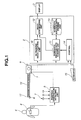
- Fig. 1 includes a mechanical scan type ultrasonic endoscope 1, an ultrasonic diagnosis apparatus 2, a display 3, an object 4, a position/orientation detecting unit 5 (as an ultrasonic scan position detecting unit), a send coil 6, a receive coil 7, an attitude detecting unit 8, a scope SW 9, an ultrasonic image creating unit 10, a schematic diagram data creating unit 11, an image synthesizing unit 12, a schematic diagram data storing unit 13, a control 14, a keyboard 15, a shaft 16, and an ultrasonic transducer 17 (as an ultrasonic sending/receiving unit).
- a system construction according to this embodiment will be described which uses the mechanical scan type ultrasonic endoscope 1 to make use of a magnetic field for detecting the position of the mechanical scan type ultrasonic endoscope 1.
- Fig. 1 shows a system construction of an ultrasonic diagnosis apparatus according to this embodiment using a magnetic field for position detection.
- the send coil 6 for generating a magnetic field is implemented at the inserting end of the mechanical scan type ultrasonic endoscope 1. Signals generated by the magnetic field by the implemented send coil 6 are output from the position/orientation detecting unit 5.
- the position/orientation detection unit 5 has the receive coil 7 for receiving the magnetic field from the send coil 6 implemented in the mechanical scan type ultrasonic endoscope 1. Furthermore, signals from the attitude detecting unit 8 attached to the object 4 for detecting the attitude of the object 4 are input to the position/orientation detecting unit 5.
- the position/orientation detecting unit 5 outputs to the ultrasonic diagnosis apparatus 2 signals indicating the attitude of the object 4 and signals indicating the ultrasonic scan position of the mechanical scan type ultrasonic endoscope 1.
- the ultrasonic transducer 17 at the inserting end is mechanically rotated by the shaft 16 of the mechanical scan type ultrasonic endoscope 1.
- ultrasonic signals are scanned circumferentially about the shaft 16.
- the ultrasonic image creating unit 10 creates an ultrasonic image from the obtained ultrasonic signals.
- the schematic diagram data creating unit 11 extracts schematic diagram data to be read from the schematic diagram data storing unit 13 from attitude position signals indicating the attitude of the object 4 obtained from the position/orientation detecting unit 5 and the position for scanning ultrasonic wave in the mechanical scan type ultrasonic endoscope 1.
- attitude position signals indicating the attitude of the object 4 obtained from the position/orientation detecting unit 5
- position for scanning ultrasonic wave in the mechanical scan type ultrasonic endoscope 1 In order to detect the position of the mechanical scan type ultrasonic endoscope 1, a reference position for starting the detection must be specified.
- the reference position may be specified by turning on the keyboard 15 or the scope SW 9 when the inserting end of the mechanical scan type ultrasonic endoscope 1 reaches the position to be the reference position.
- Fig. 2 shows a simplified construction of the mechanical scan type ultrasonic endoscope 1 and a state where the mechanical scan type ultrasonic endoscope 1 is being inserted to the body cavity.
- the mechanical scan type ultrasonic endoscope 1 is fastened at some positions in the body cavity.
- the ultrasonic transducer 17 at the inserting end is rotated about the shaft 16 so that the shaft 16 is twisted in the mechanical scan type ultrasonic endoscope 1 for scanning ultrasonic wave.
- the ultrasonic image may be displaced upward.
- a position sensor 28 for detecting the position is provided at the inserting end of the mechanical scan type ultrasonic endoscope 1.
- the image synthesizing unit 12 synthesizes the ultrasonic image created by the ultrasonic image creating potion 10 and the schematic diagram data created by the schematic diagram data creating unit 11. Then, the display 3 displays on the same screen the ultrasonic image and the schematic diagram corresponding to the position for scanning ultrasonic wave.
- Fig. 3 shows a screen display example.
- Fig. 3 shows an example displaying the ultrasonic image on the left and the schematic diagram on the right.
- the scanning surface of the mechanical scan type ultrasonic endoscope 1 and the inserting form may be displayed together.
- only the scanning surface or only the schematic diagram without the scanning surface may be displayed.
- the schematic diagram on the right of Fig. 3 may be a schema image, a CT image of an object, an MRI image or a human body real optical image obtained from a frozen dead body.
- the ultrasonic image and the schematic diagram of the scanning position are displayed in alignment.
- the schematic diagram may be displayed over the ultrasonic image.
- a schematic diagram is displayed together with an ultrasonic image such that the part of an object to be observed can be easily identified. Furthermore, a desired tomography plane can be easily extracted.
- a second embodiment is substantially the same as the first embodiment, and only the differences will be described below.
- the same reference numerals are given to the same components here, and the description will be omitted.
- the first embodiment applies a mechanical scan type ultrasonic endoscope but may alternatively apply an ultrasonic endoscope for electrically switching ultrasonic transducers for scanning.
- the second embodiment will be described below.
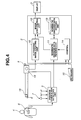
- Fig. 4 shows a system construction of an ultrasonic diagnosis apparatus according to the second embodiment.
- Fig. 4 includes an ultrasonic diagnosis apparatus 2, a display 3, an object 4, a position/orientation detecting unit 5, a send coil 6, a receive coil 7, an attitude detecting unit 8, a scope SW 9, an ultrasonic image creating unit 10, a schematic diagram data creating unit 11, an image synthesizing unit 12, a schematic diagram data storing unit 13, a control 14, a keyboard 15, ultrasonic transducers 18, and an electronic radial scan type ultrasonic endoscope 19.
- a system construction according to this embodiment uses a magnetic field for position detection.
- the ultrasonic diagnosis apparatus 2 uses the electronic radial scan type ultrasonic endoscope 19 having an array of the ultrasonic transducers 18 including multiple ultrasonic transducers around an inserting axis and includes the send coil 6, which is a position sensor, at the inserting end.
- the electronic scan type ultrasonic endoscope 19 electrically switches ultrasonic transducers for transmitting and receiving ultrasonic signals and scans ultrasonic wave on the circumference of the inserting axis. Therefore, like the mechanical scan type ultrasonic endoscope 1 according to the first embodiment, the upward displacement of an ultrasonic image due to the twist of the shaft 16 does not occur. By providing a position sensor at the inserting end, the ultrasonic scan position can be accurately identified.
- the electronic radial scan type ultrasonic endoscope 19 does not have to have the ultrasonic transducers 18 on the entire circumference of the inserting axis but may be partially lacking, such as in a fan shape of 270 degrees.
- the ultrasonic image creating unit 10 creates an ultrasonic image from ultrasonic signals obtained by scanning the ultrasonic transducers 18. Furthermore, the schematic diagram data creating unit 11 detects the attitude of the object 4 obtained from the position/orientation detecting unit 5 and the position for scanning ultrasonic wave of the electronic radial scan type ultrasonic endoscope 19. The schematic diagram data creating unit 11 reads from the schematic diagram data storing unit 13 schematic diagram data corresponding to the position for scanning ultrasonic wave by the electronic radial scan type ultrasonic endoscope 19. Then, the ultrasonic image obtained by the ultrasonic image creating unit 10 and the schematic diagram are displayed on the same screen.
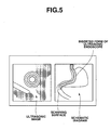
- Fig. 5 shows a screen display example.
- Fig. 5 shows an ultrasonic image by the electronic radial scan type ultrasonic endoscope 19 on the left and a schematic diagram corresponding to the ultrasonic scan position on the right.
- the schematic diagram in Fig. 5 may include the scanning surface and inserting form of the electronic radial scan type ultrasonic endoscope 19. Alternatively, only the scanning plane or the schematic diagram may be included.
- an ultrasonic image and a schematic diagram are displayed together.
- the part being observed of an object can be easily identified, and a desired tomography plane can be easily extracted.
- the second embodiment adopts an electronic radial scan type ultrasonic endoscope.
- the second embodiment may adopt an electronic convex scan type ultrasonic endoscope, which includes an array of ultrasonic transducers and electrically switches transducers.
- Fig. 6 shows an electronic radial scan type ultrasonic endoscope.
- Fig. 7 shows a mechanical scan type ultrasonic endoscope.
- Fig. 8 shows an electronic convex scan type ultrasonic endoscope.
- Figs. 6 to 8 show differences between the arrangements and ultrasonic scanning surfaces of the ultrasonic transducers of the ultrasonic endoscopes.
- the electronic radial scan type ultrasonic endoscope has an array of ultrasonic transducers on the circumference of the inserting axis and ultrasonically scans on the circumference of the inserting axis.
- the mechanical scan type ultrasonic endoscope mechanically rotates ultrasonic transducers and ultrasonically scans on the circumference of the inserting axis.
- the electronic convex scan type ultrasonic endoscope has a fan-shaped array of ultrasonic transducers at the end of the inserting axis and ultrasonically scans the surface parallel to the inserting axis.
- the electronic convex scan type ultrasonic endoscope scans in the direction different from the scanning direction of the mechanical scan type ultrasonic endoscope and the electronic radial scan type ultrasonic endoscope.
- the electronic convex scan type ultrasonic endoscope may be also applied to the ultrasonic diagnosis apparatus so as to achieve easily-understandable diagnosis.
- Fig. 9 shows a display example of an electronic convex scan type ultrasonic endoscope.
- Fig. 9 shows an ultrasonic image on the left and a schematic diagram corresponding to the ultrasonic scanning position on the right.
- the scanning surface shown in the schematic diagram on the right is represented differently from the first and second embodiments.
- the schematic diagram on the right may include the ultrasonic scanning surface and inserting form of the ultrasonic endoscope. Alternatively, only the ultrasonic scanning surface or the schematic diagram may be included.
- a third embodiment is substantially the same as the first embodiment. Therefore, only differences will be described.
- the same reference numerals are given to the same components, and the description will be omitted here.
- the ultrasonic diagnosis apparatus 2 Since the ultrasonic diagnosis apparatus 2 according to the first and second embodiments has the construction shown in Fig. 10, the name of a part can be displayed over an ultrasonic image in accordance with the ultrasonic scanning. The construction will be described hereinafter.
- Fig. 10 shows an ultrasonic diagnosis apparatus 2 according to the third embodiment.
- the ultrasonic diagnosis apparatus 2 includes an ultrasonic image creating unit 10, a name-of-part superposing unit 20, a name-of-part extracting unit 25, and a display 3.
- the name-of-part extracting unit 25 according to the third embodiment includes a schematic diagram area extracting unit 21, a reference schematic diagram storing unit 22, a name-of-part storing unit 23 and a name-of-part/area correspondence unit 24.
- the ultrasonic image creating unit 10 creates ultrasonic image data from ultrasonic signals obtained by transmitting and receiving ultrasonic wave within an object.
- the schematic diagram area extracting unit 21 detects an area of the scanning position of the ultrasonic endoscope from reference schematic diagram data of the reference schematic diagram storing unit 22 based on the signals of the position and direction for detecting the position of the ultrasonic endoscope and the attitude of the object, which have been input to the name-of-part extracting unit 25. Then, the schematic diagram area extracting unit 21 outputs ultrasonic scan area data.
- the name-of-part/area correspondence unit 24 reads from the name-of-part storing part 23 name-of-part data corresponding to the output ultrasonic scan area data.
- the name-of-part superposing part 20 displays on the screen of the display 3 the read name-of-part data over the ultrasonic image.
- Fig. 11 shows a screen display example.
- a name of a part is superposed on an ultrasonic image. Therefore, the correspondence of the ultrasonic image to an organ becomes clearer, which allows the operator to provide more easily understandable diagnoses.
- the part can be colored.
- the constructions and operations of variation examples of the name-of-part extracting unit 25 will be described below.
- Fig. 12 shows an ultrasonic diagnosis apparatus 2 according to a first variation example of the third embodiment.
- the ultrasonic diagnosis apparatus 2 includes an ultrasonic image creating unit 10, a name-of-part superposing unit 20, a name-of-part extracting unit 25 and a display 3.
- the name-of-part extracting unit 25 of the first variation example includes a schematic diagram area extracting unit 21, a reference schematic diagram storing unit 22, a part area reading unit 26, and a part area storing unit 27.
- the ultrasonic image creating unit 10 creates ultrasonic image data from ultrasonic signals obtained by transmitting and receiving ultrasonic wave.
- the schematic diagram area extracting unit 21 detects an area being scanned by the ultrasonic endoscope from the reference schematic diagram data of the reference schematic diagram storing unit 22 based on the position and direction signals for detecting the position of the ultrasonic endoscope and the attitude of an object, which have been input to the name-of-part extracting unit 25. Then, the ultrasonic scan area data is output.
- the part area reading unit 26 reads part area data to be colored in accordance with the ultrasonic scan area data from the part area storing unit 27 based on the ultrasonic scan area data output from the schematic diagram area extracting unit 21.
- the name-of-part superposing unit 20 superposes and displays the read part area colored data on the ultrasonic image.
- Fig. 13 shows a screen display example. As shown in Fig. 13, a part on an ultrasonic image is colored. Therefore, according to the first variation example of the third embodiment, the correspondence of the ultrasonic image to the organ becomes clearer, which allows an operator to provide more easily understandable diagnoses. Furthermore, an operator can provide more easily understandable diagnoses by coloring parts in different colors.
- Fig. 14 shows an ultrasonic diagnosis apparatus 2 according to a second variation example of the third embodiment.
- the ultrasonic diagnosis apparatus 2 includes an ultrasonic image creating unit 10, a schematic diagram data creating unit 11, a schematic diagram data storing unit 13, an image creating unit 12, a name-of-part superposing unit 20, a name-of-part extracting unit 25 and a display 3.
- the ultrasonic image creating unit 10 creates ultrasonic image data from ultrasonic signals obtained by transmitting and receiving ultrasonic wave.
- Signals of the position and direction for scanning ultrasonic wave of the ultrasonic endoscope are input to the name-of-part extracting unit 25, and the name of the part is therefore output. Then, the name-of-part superposing unit 20 superposes the name of the part on the ultrasonic image.
- the schematic diagram data creating unit 11 reads schematic diagram data corresponding to the ultrasonic-wave scanning position from the schematic diagram data storing unit 13 based on the input signals of the position and direction for scanning ultrasonic wave of the ultrasonic endoscope.
- the image synthesizing unit 12 synthesizes the read schematic diagram data and the name-of-part superposed ultrasonic image output from the name-of-part superposing unit 20. Then, the display 3 displays the image on the same screen.
- Fig. 15 shows an image display example.
- An ultrasonic image having a name of a part over an ultrasonic image is displayed on the left while the schematic diagram is displayed on the right.
- the ultrasonic-wave scanning surface and the inserting form of the ultrasonic endoscope may be displayed.
- only the ultrasonic-wave scanning surface or the schematic diagram may be displayed.
- a fourth embodiment is substantially the same as the first embodiment. Therefore, only the differences will be described.
- the same reference numerals are given to the same components, and the description will be omitted.
- the schematic data storing unit 13 includes schematic diagram data storage devices for types of images including schema images, CT images and real optical human body images obtained from frozen dead bodies.
- the schematic diagram data storing unit 13 to be referred by the schematic data reading unit 11 may be switched by a switcher 29.
- a fifth embodiment is substantially the same as the first embodiment. Therefore, only the differences will be described.
- the same reference numerals are given to the same components, and the description will be omitted here.
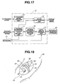
- a large amount of capacity is required, which costs a lot. Therefore, as shown in Fig. 17, according to the fifth embodiment, only the minimum schematic diagram data to be used for diagnoses is stored in a minimum schematic diagram data storing unit 30 while the other schematic diagram data is stored in an external backing storage 32.
- the external backing storage 32 is connected to the ultrasonic diagnosis apparatus 2.
- the schematic diagram data in the minimum schematic diagram data storing unit 30 is updated through a data update control 31.
- Fig. 18 shows an egg-shaped capsule type ultrasonic sonde 33.
- the capsule type ultrasonic sonde 33 includes a cover member 34, an array transducer 36, a send antenna 37, a battery 38, a magnetic source 39, a transmitter 40, a coil 41, a sending/receiving circuit 42 and a duct 43.
- the capsule type ultrasonic sonde 33 transmits and receives ultrasonic wave by driving the array transducer from the sending/receiving circuit 42 by using energy of the battery 38, switches transducers for transmitting and receiving and scans the ultrasonic wave.
- ultrasonic wave is received, is amplified in the sending/receiving circuit 42 and is sent from the send antenna 37 to an external ultrasonic synthesizing operation apparatus (not shown). Then, an ultrasonic image is created.
- a positional signal is sent from the transmitter 40 through the coil 41 and is received by the receive coil 7 as shown in Fig. 1.
- the position/orientation detecting unit 6 detects the position of the capsule type ultrasonic sonde 33.
- an ultrasonic diagnosis apparatus is effective for observing concerned parts within a body cavity through ultrasonic tomograms.
Landscapes
- Health & Medical Sciences (AREA)
- Life Sciences & Earth Sciences (AREA)
- Engineering & Computer Science (AREA)
- Medical Informatics (AREA)
- Surgery (AREA)
- Pathology (AREA)
- Radiology & Medical Imaging (AREA)
- Biophysics (AREA)
- Biomedical Technology (AREA)
- Heart & Thoracic Surgery (AREA)
- Physics & Mathematics (AREA)
- Molecular Biology (AREA)
- Nuclear Medicine, Radiotherapy & Molecular Imaging (AREA)
- Animal Behavior & Ethology (AREA)
- General Health & Medical Sciences (AREA)
- Public Health (AREA)
- Veterinary Medicine (AREA)
- Computer Networks & Wireless Communication (AREA)
- Computer Vision & Pattern Recognition (AREA)
- Ultra Sonic Daignosis Equipment (AREA)
- Investigating Or Analyzing Materials By The Use Of Ultrasonic Waves (AREA)
Abstract
Description
Claims (16)
- An ultrasonic diagnosis apparatus, comprising:an ultrasonic-wave transmitting/receiving unit for transmitting and receiving ultrasonic wave to or from an object;an ultrasonic-wave scanning position detecting unit for detecting a position of the ultrasonic-wave transmitting/receiving unit for transmitting and receiving ultrasonic wave;an ultrasonic image creating unit for creating an ultrasonic image based on the ultrasonic signals; anda control for obtaining information relating to a part of the object corresponding to position information obtained by the ultrasonic-wave scanning position detecting unit from an anatomical data holding unit having human body anatomical data and displaying the information and the ultrasonic image on the same screen.
- An ultrasonic diagnosis apparatus according to Claim 1, wherein the information relating to a part of the object is anatomical image information of the part of the object, and the anatomical data of the human body is schematic diagram data of the human body.
- An ultrasonic diagnosis apparatus according to Claim 1, wherein the information relating to a part of the object is a name of the part of the object, and the anatomical data of the human body is a name of the part of the human body.
- An ultrasonic diagnosis apparatus according to Claim 1, wherein the anatomical data of the human body is data on a part area of the human body;
wherein the control associates the part of the object with data on a part area of the human body, colors the part corresponding to the part of the ultrasonic image and causes a display to display the colored part. - An ultrasonic diagnosis apparatus according to Claim 1, further comprising:a schematic diagram data storing unit, which is the anatomical data holding unit provided in the ultrasonic diagnosis apparatus, for storing schematic diagram data of a human body; anda schematic diagram creating unit for reading data from the schematic diagram data storing unit and for creating a schematic diagram corresponding to the position detected by the ultrasonic-wave scanning position detecting unit.
- An ultrasonic diagnosis apparatus according to Claim 5,
wherein the human body schematic diagram data is a human body schema image, a CT image of an object, an MRI image of an object or a human body real optical image obtained from a frozen dead body. - An ultrasonic diagnosis apparatus according to Claim 5, further comprising:a position-marked schematic diagram creating unit for creating a position-marked schematic diagram indicating an ultrasonic-wave scanning position by showing schematic diagram data read in accordance with the ultrasonic-wave scanning position over schematic diagram data created by the schematic diagram creating unit.
- An ultrasonic diagnosis apparatus according to Claim 6,
wherein the schematic diagram data storing unit further includes:wherein the control further controls the switching by the schematic diagram data switching unit.a schematic diagram data switching unit for storing different kinds of multiple pieces of schematic diagram data among human body schema images, object CT images, object MRI images and human body real optical images obtained from frozen dead bodies and for switching the multiple schematic diagram data storing units, - An ultrasonic diagnosis apparatus according to Claim 1,
wherein an ultrasonic image is created from ultrasonic signals obtained by transmitting and receiving ultrasonic wave to or from the inside of the object by using a round-shaped ultrasonic sonde easily swallowable from the mouth cavity of the object. - An ultrasonic diagnosis apparatus according to Claim 1,
wherein an ultrasonic image is created from ultrasonic signals obtained by transmitting and receiving ultrasonic wave to or from the inside of the object by using a long and narrow, flexible ultrasonic probe to be inserted to the object;
wherein the ultrasonic probe is:an electronic radial scan type ultrasonic endoscope having an array of ultrasonic transducers around an inserting axis;an electronic convex scan type ultrasonic endoscope having ultrasonic transducers in a fan shape at one end of the inserting axis; ora mechanical scan type ultrasonic endoscope in which an ultrasonic transducer piece rotates about the inserting axis. - An ultrasonic diagnosis apparatus, comprising:ultrasonic-wave transmitting/receiving means for transmitting and receiving ultrasonic wave to or from an object;ultrasonic-wave scanning position detecting means for detecting the position of the ultrasonic-wave transmitting/receiving means for transmitting and receiving ultrasonic wave;ultrasonic image creating means for creating an ultrasonic image based on the ultrasonic signals; andcontrol means for obtaining information relating to a part of the object in accordance with the position information obtained by the ultrasonic-wave scanning position detecting means from an anatomical data holding unit having human body anatomical data and displaying the information and the ultrasonic image on the same screen.
- A method for displaying an ultrasonic diagnosis image, the method comprising:an ultrasonic-wave transmitting/receiving step for transmitting and receiving ultrasonic wave to or from an object by using an ultrasonic-wave transmitting/receiving unit;an ultrasonic-wave scanning position detecting step for detecting the position of the ultrasonic-wave transmitting/receiving unit for transmitting and receiving ultrasonic wave;an ultrasonic image creating step for creating an ultrasonic image based on the ultrasonic signals; anda control step for obtaining information relating to a part of the object in accordance with the position information obtained by the ultrasonic-wave scanning position detecting step from an anatomical data holding unit having human body anatomical data and displaying the information and the ultrasonic image on the same screen.
- A method for displaying an ultrasonic diagnosis image according to Claim 12, wherein the information relating to a part of the object is anatomical image information of the part of the object, and the anatomical data of the human body is schematic diagram data of the human body.
- A method for displaying an ultrasonic diagnosis image according to Claim 12, wherein information relating to a part of the object is a name of the part of the object, and the anatomical data of the human body is a name of the part of the human body.
- A method for displaying an ultrasonic diagnosis image according to Claim 12, wherein the anatomical data of the human body is data on a part area of the human body;
wherein the control step associates the part of the object with data on a part area of the human body, colors the part corresponding to the part on the ultrasonic image and causes a display to display the colored part. - A method for displaying an ultrasonic diagnosis image according to Claim 12, further comprising:a schematic diagram data storing step, which is an anatomical data holding step, for storing schematic diagram data of a human body to the schematic diagram data storing unit provided in the ultrasonic diagnosis apparatus; anda schematic diagram creating step for reading data from the schematic diagram data storing unit and for creating a schematic diagram corresponding to the position detected by the ultrasonic-wave scanning position detecting unit.
Applications Claiming Priority (3)
| Application Number | Priority Date | Filing Date | Title |
|---|---|---|---|
| JP2002283803A JP2004113629A (en) | 2002-09-27 | 2002-09-27 | Ultrasonograph |
| JP2002283803 | 2002-09-27 | ||
| PCT/JP2003/011694 WO2004028374A1 (en) | 2002-09-27 | 2003-09-12 | Ultrasonograph |
Publications (3)
| Publication Number | Publication Date |
|---|---|
| EP1543776A1 true EP1543776A1 (en) | 2005-06-22 |
| EP1543776A4 EP1543776A4 (en) | 2008-04-02 |
| EP1543776B1 EP1543776B1 (en) | 2012-01-11 |
Family
ID=32040572
Family Applications (1)
| Application Number | Title | Priority Date | Filing Date |
|---|---|---|---|
| EP03798404A Expired - Lifetime EP1543776B1 (en) | 2002-09-27 | 2003-09-12 | Ultrasonograph |
Country Status (5)
| Country | Link |
|---|---|
| US (1) | US20050203417A1 (en) |
| EP (1) | EP1543776B1 (en) |
| JP (1) | JP2004113629A (en) |
| AT (1) | ATE540618T1 (en) |
| WO (1) | WO2004028374A1 (en) |
Cited By (3)
| Publication number | Priority date | Publication date | Assignee | Title |
|---|---|---|---|---|
| WO2005104955A1 (en) | 2004-04-30 | 2005-11-10 | Olympus Corporation | Ultrasonic diagnosis device |
| EP1872707A1 (en) * | 2006-06-29 | 2008-01-02 | Olympus Medical Systems Corp. | Body cavity probe apparatus |
| EP2180831A4 (en) * | 2007-08-16 | 2011-03-02 | Rdc Rafael Dev Corp Ltd | An ultrasonic capsule |
Families Citing this family (29)
| Publication number | Priority date | Publication date | Assignee | Title |
|---|---|---|---|---|
| JP4167162B2 (en) * | 2003-10-14 | 2008-10-15 | アロカ株式会社 | Ultrasonic diagnostic equipment |
| JP4263579B2 (en) * | 2003-10-22 | 2009-05-13 | アロカ株式会社 | Ultrasonic diagnostic equipment |
| JP4681857B2 (en) * | 2004-11-25 | 2011-05-11 | オリンパス株式会社 | Ultrasonic diagnostic equipment |
| CN1873651A (en) * | 2005-05-31 | 2006-12-06 | 株式会社东芝 | Medical report preparing system and ultrasound diagnostic apparatus incorporating the system |
| JP2007029456A (en) * | 2005-07-27 | 2007-02-08 | Matsushita Electric Ind Co Ltd | Ultrasonic diagnostic equipment |
| JP4700434B2 (en) * | 2005-08-03 | 2011-06-15 | オリンパスメディカルシステムズ株式会社 | Ultrasonic diagnostic equipment |
| JP4875416B2 (en) | 2006-06-27 | 2012-02-15 | オリンパスメディカルシステムズ株式会社 | Medical guide system |
| WO2008030482A2 (en) | 2006-09-06 | 2008-03-13 | Innurvation Inc | System and method for acoustic information exchange involving an ingestible low power capsule |
| US7925068B2 (en) * | 2007-02-01 | 2011-04-12 | General Electric Company | Method and apparatus for forming a guide image for an ultrasound image scanner |
| JP5226244B2 (en) * | 2007-05-07 | 2013-07-03 | オリンパスメディカルシステムズ株式会社 | Medical guide system |
| JP5576041B2 (en) * | 2008-06-09 | 2014-08-20 | 日立アロカメディカル株式会社 | Ultrasonic diagnostic equipment |
| WO2010005571A2 (en) | 2008-07-09 | 2010-01-14 | Innurvation, Inc. | Displaying image data from a scanner capsule |
| CN102159138B (en) * | 2008-07-15 | 2013-12-25 | 株式会社日立医疗器械 | Ultrasonic diagnostic device and display method of the ultrasonic diagnostic device |
| KR101182880B1 (en) * | 2009-01-28 | 2012-09-13 | 삼성메디슨 주식회사 | Ultrasound system and method for providing image indicator |
| US20110077719A1 (en) * | 2009-09-30 | 2011-03-31 | Broadcom Corporation | Electromagnetic power bio-medical unit |
| US8647259B2 (en) * | 2010-03-26 | 2014-02-11 | Innurvation, Inc. | Ultrasound scanning capsule endoscope (USCE) |
| EP2491865A1 (en) | 2011-02-24 | 2012-08-29 | Samsung Medison Co., Ltd. | Ultrasound system for providing image indicator |
| CN103796595B (en) * | 2012-08-31 | 2016-04-13 | 株式会社东芝 | Medical report producing device and medical diagnostic imaging apparatus |
| KR102002408B1 (en) * | 2012-09-12 | 2019-07-24 | 삼성전자주식회사 | Apparatus and method for generating ultrasonic image |
| US9820717B2 (en) * | 2013-02-22 | 2017-11-21 | Toshiba Medical Systems Corporation | Apparatus and method for fetal image rendering |
| CN105421175B (en) * | 2015-12-18 | 2017-10-03 | 安徽优特公路养护科技有限公司 | A kind of use high polymer administers the preamble processing method and system of roadbase disease |
| JP6615603B2 (en) | 2015-12-24 | 2019-12-04 | キヤノンメディカルシステムズ株式会社 | Medical image diagnostic apparatus and medical image diagnostic program |
| WO2019138773A1 (en) | 2018-01-10 | 2019-07-18 | 富士フイルム株式会社 | Medical image processing apparatus, endoscope system, medical image processing method, and program |
| KR102608821B1 (en) * | 2018-02-08 | 2023-12-04 | 삼성메디슨 주식회사 | Wireless ultrasound probe and ultrasound imaging apparatus connected to the wireless ultrasound probes and operating the same |
| JP6665214B2 (en) * | 2018-02-26 | 2020-03-13 | キヤノンメディカルシステムズ株式会社 | Apparatus and processing program |
| WO2020174778A1 (en) | 2019-02-28 | 2020-09-03 | 富士フイルム株式会社 | Ultrasonic endoscopic system and operating method of ultrasonic endoscopic system |
| JP7823490B2 (en) * | 2022-05-06 | 2026-03-04 | コニカミノルタ株式会社 | Ultrasound diagnostic device, ultrasound diagnostic system and program |
| JP2023166905A (en) * | 2022-05-10 | 2023-11-22 | コニカミノルタ株式会社 | Ultrasonic diagnostic device, ultrasonic diagnostic device control method, and ultrasonic diagnostic device control program |
| JP2024106433A (en) * | 2023-01-27 | 2024-08-08 | 富士フイルムヘルスケア株式会社 | Ultrasound information processing device, ultrasound diagnostic system, and ultrasound diagnostic device |
Family Cites Families (16)
| Publication number | Priority date | Publication date | Assignee | Title |
|---|---|---|---|---|
| JPS6066735A (en) | 1983-09-22 | 1985-04-16 | 株式会社島津製作所 | Diagnosis site display method for ultrasound diagnostic equipment |
| US5335663A (en) * | 1992-12-11 | 1994-08-09 | Tetrad Corporation | Laparoscopic probes and probe sheaths useful in ultrasonic imaging applications |
| US5394878A (en) * | 1993-07-13 | 1995-03-07 | Frazin; Leon J. | Method for two dimensional real time color doppler ultrasound imaging of bodily structures through the gastro intestinal wall |
| WO1996005768A1 (en) * | 1994-08-19 | 1996-02-29 | Biosense, Inc. | Medical diagnosis, treatment and imaging systems |
| JP3349233B2 (en) * | 1993-12-28 | 2002-11-20 | オリンパス光学工業株式会社 | Ultrasound diagnostic equipment |
| JP3114553B2 (en) * | 1995-02-17 | 2000-12-04 | 富士写真光機株式会社 | Ultrasound diagnostic equipment |
| JPH08257028A (en) * | 1995-03-27 | 1996-10-08 | Ge Yokogawa Medical Syst Ltd | Body pattern display method and ultrasonic diagnostic system |
| DE19751761B4 (en) * | 1997-04-11 | 2006-06-22 | Brainlab Ag | System and method for currently accurate detection of treatment targets |
| JPH1147133A (en) * | 1997-08-07 | 1999-02-23 | Nippon Telegr & Teleph Corp <Ntt> | Ultrasound diagnostic equipment |
| JP4248615B2 (en) * | 1997-10-23 | 2009-04-02 | オリンパス株式会社 | Ultrasound diagnostic imaging equipment |
| JP2000023980A (en) | 1998-07-08 | 2000-01-25 | Olympus Optical Co Ltd | Ultrasonograph |
| JP3776597B2 (en) * | 1998-07-13 | 2006-05-17 | オリンパス株式会社 | Ultrasonic diagnostic equipment |
| JP4350214B2 (en) * | 1999-07-06 | 2009-10-21 | 株式会社東芝 | Ultrasonic diagnostic equipment |
| US6511431B2 (en) * | 2000-05-10 | 2003-01-28 | Pentax Corporation | Radial scan, forward viewing ultrasonic endoscope |
| US6589267B1 (en) * | 2000-11-10 | 2003-07-08 | Vasomedical, Inc. | High efficiency external counterpulsation apparatus and method for controlling same |
| JP3756797B2 (en) * | 2001-10-16 | 2006-03-15 | オリンパス株式会社 | Capsule type medical equipment |
-
2002
- 2002-09-27 JP JP2002283803A patent/JP2004113629A/en active Pending
-
2003
- 2003-09-12 AT AT03798404T patent/ATE540618T1/en active
- 2003-09-12 EP EP03798404A patent/EP1543776B1/en not_active Expired - Lifetime
- 2003-09-12 WO PCT/JP2003/011694 patent/WO2004028374A1/en not_active Ceased
-
2005
- 2005-03-21 US US11/085,343 patent/US20050203417A1/en not_active Abandoned
Cited By (5)
| Publication number | Priority date | Publication date | Assignee | Title |
|---|---|---|---|---|
| WO2005104955A1 (en) | 2004-04-30 | 2005-11-10 | Olympus Corporation | Ultrasonic diagnosis device |
| EP1741390A4 (en) * | 2004-04-30 | 2009-08-05 | Olympus Corp | Ultrasonic diagnosis device |
| US7736316B2 (en) | 2004-04-30 | 2010-06-15 | Olympus Corporation | Ultrasonic diagnosis apparatus |
| EP1872707A1 (en) * | 2006-06-29 | 2008-01-02 | Olympus Medical Systems Corp. | Body cavity probe apparatus |
| EP2180831A4 (en) * | 2007-08-16 | 2011-03-02 | Rdc Rafael Dev Corp Ltd | An ultrasonic capsule |
Also Published As
| Publication number | Publication date |
|---|---|
| US20050203417A1 (en) | 2005-09-15 |
| EP1543776B1 (en) | 2012-01-11 |
| JP2004113629A (en) | 2004-04-15 |
| ATE540618T1 (en) | 2012-01-15 |
| EP1543776A4 (en) | 2008-04-02 |
| WO2004028374A1 (en) | 2004-04-08 |
Similar Documents
| Publication | Publication Date | Title |
|---|---|---|
| EP1543776B1 (en) | Ultrasonograph | |
| JP4681857B2 (en) | Ultrasonic diagnostic equipment | |
| CN100475149C (en) | Ultrasonic diagnostic device | |
| JP3354619B2 (en) | Ultrasound diagnostic equipment | |
| JP2006255083A (en) | Ultrasonic image formation method and ultrasonic diagnostic equipment | |
| CN101516271B (en) | Ultrasonic image processing device and ultrasonic image diagnostic device | |
| JP3808990B2 (en) | Ultrasound diagnostic imaging equipment | |
| JP2010088699A (en) | Medical image processing system | |
| JP4350214B2 (en) | Ultrasonic diagnostic equipment | |
| JP2004121488A (en) | Ultrasonograph | |
| JP2001333902A (en) | Ultrasonic diagnostic device | |
| JP4119530B2 (en) | Endoscope device and position detection catheter inserted into endoscope | |
| CN103930039A (en) | Ultrasonic diagnostic device | |
| JP4248615B2 (en) | Ultrasound diagnostic imaging equipment | |
| JPS62284635A (en) | Ultrasonic diagnostic apparatus | |
| JP2019063508A (en) | Ultrasonic diagnostic apparatus and control program | |
| JP4474608B2 (en) | Ultrasonic diagnostic equipment | |
| JP2007268148A (en) | Ultrasonic diagnostic equipment | |
| JP2007037564A (en) | Ultrasonic diagnostic equipment | |
| JPH11113912A (en) | Ultrasonograph | |
| JP4198130B2 (en) | Ultrasonic diagnostic equipment | |
| JP2001198125A (en) | Image diagnostic device | |
| CN201996577U (en) | Electronic laryngoscope system with color Doppler ultrasonic scanning function | |
| CN102028502B (en) | Electronic laryngoscope system with color Doppler ultrasound scanning function | |
| JP2003180696A (en) | Ultrasonic diagnostic equipment |
Legal Events
| Date | Code | Title | Description |
|---|---|---|---|
| PUAI | Public reference made under article 153(3) epc to a published international application that has entered the european phase |
Free format text: ORIGINAL CODE: 0009012 |
|
| 17P | Request for examination filed |
Effective date: 20050322 |
|
| AK | Designated contracting states |
Kind code of ref document: A1 Designated state(s): AT BE BG CH CY CZ DE DK EE ES FI FR GB GR HU IE IT LI LU MC NL PT RO SE SI SK TR |
|
| A4 | Supplementary search report drawn up and despatched |
Effective date: 20080229 |
|
| 17Q | First examination report despatched |
Effective date: 20080807 |
|
| GRAP | Despatch of communication of intention to grant a patent |
Free format text: ORIGINAL CODE: EPIDOSNIGR1 |
|
| GRAS | Grant fee paid |
Free format text: ORIGINAL CODE: EPIDOSNIGR3 |
|
| GRAA | (expected) grant |
Free format text: ORIGINAL CODE: 0009210 |
|
| AK | Designated contracting states |
Kind code of ref document: B1 Designated state(s): AT BE BG CH CY CZ DE DK EE ES FI FR GB GR HU IE IT LI LU MC NL PT RO SE SI SK TR |
|
| REG | Reference to a national code |
Ref country code: GB Ref legal event code: FG4D |
|
| REG | Reference to a national code |
Ref country code: CH Ref legal event code: EP |
|
| REG | Reference to a national code |
Ref country code: AT Ref legal event code: REF Ref document number: 540618 Country of ref document: AT Kind code of ref document: T Effective date: 20120115 |
|
| REG | Reference to a national code |
Ref country code: IE Ref legal event code: FG4D |
|
| REG | Reference to a national code |
Ref country code: DE Ref legal event code: R096 Ref document number: 60339715 Country of ref document: DE Effective date: 20120308 |
|
| REG | Reference to a national code |
Ref country code: NL Ref legal event code: VDEP Effective date: 20120111 |
|
| PG25 | Lapsed in a contracting state [announced via postgrant information from national office to epo] |
Ref country code: SI Free format text: LAPSE BECAUSE OF FAILURE TO SUBMIT A TRANSLATION OF THE DESCRIPTION OR TO PAY THE FEE WITHIN THE PRESCRIBED TIME-LIMIT Effective date: 20120111 |
|
| PG25 | Lapsed in a contracting state [announced via postgrant information from national office to epo] |
Ref country code: BG Free format text: LAPSE BECAUSE OF FAILURE TO SUBMIT A TRANSLATION OF THE DESCRIPTION OR TO PAY THE FEE WITHIN THE PRESCRIBED TIME-LIMIT Effective date: 20120411 Ref country code: NL Free format text: LAPSE BECAUSE OF FAILURE TO SUBMIT A TRANSLATION OF THE DESCRIPTION OR TO PAY THE FEE WITHIN THE PRESCRIBED TIME-LIMIT Effective date: 20120111 Ref country code: BE Free format text: LAPSE BECAUSE OF FAILURE TO SUBMIT A TRANSLATION OF THE DESCRIPTION OR TO PAY THE FEE WITHIN THE PRESCRIBED TIME-LIMIT Effective date: 20120111 |
|
| PG25 | Lapsed in a contracting state [announced via postgrant information from national office to epo] |
Ref country code: PT Free format text: LAPSE BECAUSE OF FAILURE TO SUBMIT A TRANSLATION OF THE DESCRIPTION OR TO PAY THE FEE WITHIN THE PRESCRIBED TIME-LIMIT Effective date: 20120511 Ref country code: FI Free format text: LAPSE BECAUSE OF FAILURE TO SUBMIT A TRANSLATION OF THE DESCRIPTION OR TO PAY THE FEE WITHIN THE PRESCRIBED TIME-LIMIT Effective date: 20120111 Ref country code: GR Free format text: LAPSE BECAUSE OF FAILURE TO SUBMIT A TRANSLATION OF THE DESCRIPTION OR TO PAY THE FEE WITHIN THE PRESCRIBED TIME-LIMIT Effective date: 20120412 |
|
| REG | Reference to a national code |
Ref country code: AT Ref legal event code: MK05 Ref document number: 540618 Country of ref document: AT Kind code of ref document: T Effective date: 20120111 |
|
| PG25 | Lapsed in a contracting state [announced via postgrant information from national office to epo] |
Ref country code: CY Free format text: LAPSE BECAUSE OF FAILURE TO SUBMIT A TRANSLATION OF THE DESCRIPTION OR TO PAY THE FEE WITHIN THE PRESCRIBED TIME-LIMIT Effective date: 20120111 |
|
| PG25 | Lapsed in a contracting state [announced via postgrant information from national office to epo] |
Ref country code: CZ Free format text: LAPSE BECAUSE OF FAILURE TO SUBMIT A TRANSLATION OF THE DESCRIPTION OR TO PAY THE FEE WITHIN THE PRESCRIBED TIME-LIMIT Effective date: 20120111 Ref country code: DK Free format text: LAPSE BECAUSE OF FAILURE TO SUBMIT A TRANSLATION OF THE DESCRIPTION OR TO PAY THE FEE WITHIN THE PRESCRIBED TIME-LIMIT Effective date: 20120111 Ref country code: EE Free format text: LAPSE BECAUSE OF FAILURE TO SUBMIT A TRANSLATION OF THE DESCRIPTION OR TO PAY THE FEE WITHIN THE PRESCRIBED TIME-LIMIT Effective date: 20120111 Ref country code: SE Free format text: LAPSE BECAUSE OF FAILURE TO SUBMIT A TRANSLATION OF THE DESCRIPTION OR TO PAY THE FEE WITHIN THE PRESCRIBED TIME-LIMIT Effective date: 20120111 Ref country code: RO Free format text: LAPSE BECAUSE OF FAILURE TO SUBMIT A TRANSLATION OF THE DESCRIPTION OR TO PAY THE FEE WITHIN THE PRESCRIBED TIME-LIMIT Effective date: 20120111 |
|
| PLBE | No opposition filed within time limit |
Free format text: ORIGINAL CODE: 0009261 |
|
| STAA | Information on the status of an ep patent application or granted ep patent |
Free format text: STATUS: NO OPPOSITION FILED WITHIN TIME LIMIT |
|
| PG25 | Lapsed in a contracting state [announced via postgrant information from national office to epo] |
Ref country code: SK Free format text: LAPSE BECAUSE OF FAILURE TO SUBMIT A TRANSLATION OF THE DESCRIPTION OR TO PAY THE FEE WITHIN THE PRESCRIBED TIME-LIMIT Effective date: 20120111 Ref country code: IT Free format text: LAPSE BECAUSE OF FAILURE TO SUBMIT A TRANSLATION OF THE DESCRIPTION OR TO PAY THE FEE WITHIN THE PRESCRIBED TIME-LIMIT Effective date: 20120111 |
|
| 26N | No opposition filed |
Effective date: 20121012 |
|
| PG25 | Lapsed in a contracting state [announced via postgrant information from national office to epo] |
Ref country code: AT Free format text: LAPSE BECAUSE OF FAILURE TO SUBMIT A TRANSLATION OF THE DESCRIPTION OR TO PAY THE FEE WITHIN THE PRESCRIBED TIME-LIMIT Effective date: 20120111 |
|
| REG | Reference to a national code |
Ref country code: DE Ref legal event code: R097 Ref document number: 60339715 Country of ref document: DE Effective date: 20121012 |
|
| PG25 | Lapsed in a contracting state [announced via postgrant information from national office to epo] |
Ref country code: MC Free format text: LAPSE BECAUSE OF NON-PAYMENT OF DUE FEES Effective date: 20120930 Ref country code: ES Free format text: LAPSE BECAUSE OF FAILURE TO SUBMIT A TRANSLATION OF THE DESCRIPTION OR TO PAY THE FEE WITHIN THE PRESCRIBED TIME-LIMIT Effective date: 20120422 |
|
| REG | Reference to a national code |
Ref country code: CH Ref legal event code: PL |
|
| GBPC | Gb: european patent ceased through non-payment of renewal fee |
Effective date: 20120912 |
|
| REG | Reference to a national code |
Ref country code: IE Ref legal event code: MM4A |
|
| PG25 | Lapsed in a contracting state [announced via postgrant information from national office to epo] |
Ref country code: CH Free format text: LAPSE BECAUSE OF NON-PAYMENT OF DUE FEES Effective date: 20120930 Ref country code: GB Free format text: LAPSE BECAUSE OF NON-PAYMENT OF DUE FEES Effective date: 20120912 Ref country code: LI Free format text: LAPSE BECAUSE OF NON-PAYMENT OF DUE FEES Effective date: 20120930 Ref country code: IE Free format text: LAPSE BECAUSE OF NON-PAYMENT OF DUE FEES Effective date: 20120912 |
|
| PG25 | Lapsed in a contracting state [announced via postgrant information from national office to epo] |
Ref country code: TR Free format text: LAPSE BECAUSE OF FAILURE TO SUBMIT A TRANSLATION OF THE DESCRIPTION OR TO PAY THE FEE WITHIN THE PRESCRIBED TIME-LIMIT Effective date: 20120111 |
|
| PG25 | Lapsed in a contracting state [announced via postgrant information from national office to epo] |
Ref country code: LU Free format text: LAPSE BECAUSE OF NON-PAYMENT OF DUE FEES Effective date: 20120912 |
|
| PG25 | Lapsed in a contracting state [announced via postgrant information from national office to epo] |
Ref country code: HU Free format text: LAPSE BECAUSE OF FAILURE TO SUBMIT A TRANSLATION OF THE DESCRIPTION OR TO PAY THE FEE WITHIN THE PRESCRIBED TIME-LIMIT Effective date: 20030912 |
|
| PGFP | Annual fee paid to national office [announced via postgrant information from national office to epo] |
Ref country code: FR Payment date: 20140906 Year of fee payment: 12 |
|
| REG | Reference to a national code |
Ref country code: FR Ref legal event code: ST Effective date: 20160531 |
|
| PG25 | Lapsed in a contracting state [announced via postgrant information from national office to epo] |
Ref country code: FR Free format text: LAPSE BECAUSE OF NON-PAYMENT OF DUE FEES Effective date: 20150930 |
|
| PGFP | Annual fee paid to national office [announced via postgrant information from national office to epo] |
Ref country code: DE Payment date: 20190918 Year of fee payment: 17 |
|
| REG | Reference to a national code |
Ref country code: DE Ref legal event code: R119 Ref document number: 60339715 Country of ref document: DE |
|
| PG25 | Lapsed in a contracting state [announced via postgrant information from national office to epo] |
Ref country code: DE Free format text: LAPSE BECAUSE OF NON-PAYMENT OF DUE FEES Effective date: 20210401 |