JP3776597B2 - Ultrasonic diagnostic equipment - Google Patents
Ultrasonic diagnostic equipment Download PDFInfo
- Publication number
- JP3776597B2 JP3776597B2 JP19764398A JP19764398A JP3776597B2 JP 3776597 B2 JP3776597 B2 JP 3776597B2 JP 19764398 A JP19764398 A JP 19764398A JP 19764398 A JP19764398 A JP 19764398A JP 3776597 B2 JP3776597 B2 JP 3776597B2
- Authority
- JP
- Japan
- Prior art keywords
- magnetic field
- ultrasonic
- signal
- image
- freeze
- Prior art date
- Legal status (The legal status is an assumption and is not a legal conclusion. Google has not performed a legal analysis and makes no representation as to the accuracy of the status listed.)
- Expired - Lifetime
Links
Images


Description
【0001】
【発明の属する技術分野】
本発明は超音波プローブにより超音波スキャンを行い、超音波断層像を得る超音波診断装置に関する。
【0002】
【従来の技術】
近年、超音波を生体にスキャンして超音波画像を得る超音波診断装置は生体の診断等に広く用いられるようになった。
この場合、得られた超音波画像がどの位置に対するものであるか分かるように位置検出機能を備えたものがある。
【0003】
例えば、特開昭62−68442号公報では、体外式の超音波診断装置において、位置検出器として磁気コイルを励振し、ボディマーク上にプローブの位置、配向を重畳表示させるようにしたものが開示されている。
また、特開平6−261900号公報では、超音波3次元画像処理を行う際、磁気コイルを常に励振し続けるようにしたものを開示している。
【0004】
【発明が解決しようとする課題】
従来例では励振するための電流を不必要に流していたため、電力が無駄になる欠点があった。また、超音波画像上にノイズとなって画質を低下させる場合もある。
【0005】
本発明は、上述した点に鑑みてなされたもので、位置検出を省電力で可能とする超音波診断装置を提供することを目的としている。
【0006】
【課題を解決するための手段】
請求項1に記載の超音波診断装置は、超音波によるスキャンを行い生体の超音波画像を得る超音波プローブと、空間に磁場を張る磁場発生手段と、該磁場を検出する磁場検出手段と、検出した該磁場から前記超音波プローブの位置を算出し、位置データを得る位置算出手段と、前記磁場発生手段を駆動する駆動手段と、を備え、
前記駆動手段は超音波画像の静止または記録を指示する指示信号及び前記スキャンに同期したスキャン信号との少なくとも一方に同期して磁場発生手段を駆動することにより、磁場発生手段を常時駆動する場合よりも電力消費を少なくできるようにしている。
請求項2に記載の超音波診断装置は、超音波によるスキャンを行い生体の超音波画像を得る超音波プローブと、該超音波画像の静止または記録を指示する入力手段と、空間に磁場を張る磁場発生手段と、該磁場を検出する磁場検出手段と、検出した該磁場から前記超音波プローブの位置を算出し、位置データを得る位置算出手段と、前記磁場発生手段を駆動する駆動手段と、を備え、
前記駆動手段が、前記入力手段の入力に同期して磁場発生手段を駆動したことを特徴とする。
請求項3に記載の超音波診断装置は、超音波によるスキャンを行い生体の超音波画像を得る超音波プローブと、該スキャンを1回行うごとにスキャン信号を生成するスキャン信号生成手段と、空間に磁場を張る磁場発生手段と、該磁場を検出する磁場検出手段と、検出した該磁場から前記超音波プローブの位置を算出し、位置データを得る位置算出手段と、前記磁場発生手段を駆動する駆動手段と、を備え、
前記駆動手段が、該スキャン信号に同期して磁場発生手段を駆動したことを特徴とする。
【0007】
【発明の実施の形態】
以下、図面を参照して本発明の実施の形態を説明する。
(第1の実施の形態)
図1ないし図3は本発明の第1の実施の形態に係り、図1は本発明の第1の実施の形態の超音波診断装置の全体構成を示し、図2は超音波プローブの操作部の構成を示し、図3は位置検出装置の構成を示す。
【0008】
図1に示す本発明の第1の実施の形態の超音波診断装置1は生体内に挿入される超音波プローブ2と、この超音波プローブ2が接続され、超音波プローブ2に内蔵された超音波振動子を駆動及び、信号処理等を行う超音波観測装置3と、この超音波観測装置3と接続され、超音波画像の表示を行う観測モニタ4と、超音波画像をプリントするビデオプリンタ5と、超音波観測装置3と接続され、画像処理を行う超音波画像処理装置6と、この超音波画像処理装置6と接続され、超音波画像の表示を行うモニタ7と、超音波プローブ2が接続され、超音波プローブ2の所定位置を検出する位置算出装置8とから構成される。
【0009】
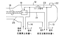
超音波プローブ2は体腔内に挿入される細長の挿入部11とその後端に設けられた操作部12とを有し、操作部12から延出された例えば2本のコード13、14(図2参照)の端部に設けたコネクタ15、16はそれぞれ超音波観測装置3と位置算出装置8に着脱自在で接続される。
【0010】
挿入部11の先端部には超音波振動子17が収納され、この超音波振動子17は挿入部11内に挿通されたフレキシブルシャフト18の先端に取り付けられ、このフレキシブルシャフト18の基端は図2に示すように操作部12内に設けたモータ19に接続されている。
【0011】
そして、このモータ19を回転させることによりその回転をフレキシブルシャフト18で伝達し、このフレキシブルシャフト18の先端に取り付けた超音波振動子17を回転駆動するようにしている。
【0012】
超音波振動子17に接続されフレキシブルシャフト18の中空部を挿通された信号線21は操作部12からさらにコード13内を挿通され、超音波観測装置3内部の図示しない送受信回路に接続され、送受信回路から超音波振動子17を駆動する送信信号が印加され、超音波振動子17は回転駆動されながら超音波をフレキシブルシャフト18の軸に垂直な方向に放射状に出射する。つまり、メカニカルにラジアルスキャン(ラジアル走査)する。
【0013】
ラジアル走査された超音波の反射波は超音波振動子17で受信されて電気信号に変換されてエコー信号となり、コード13内の信号線21により超音波観測装置3内部の図示しないで送受信回路に伝送される。そして、送受信回路等の信号処理系で増幅、検波、A/D変換等されてメモリに画像データが一時格納され、さらにDSC等を経てビデオ信号に変換され、リアルタイムで観測モニタ4及びビデオプリンタ5に入力される。
【0014】
また、図2に示すように操作部12にはフリーズ・レリーズスイッチ22が設けてあり、このスイッチ22を押すとフリーズ信号が発生し、このフリーズ信号は信号線23を介してモータ19(より詳細にはモータ駆動回路)に印加されると共に、超音波観測装置3と、位置算出装置8とに入力される。モータ19はフリーズ信号により回転を停止する。
【0015】
また、超音波観測装置3では、フリーズ信号により、メモリに画像データの上書きを禁止して、フリーズ画に相当するビデオ信号を観測モニタ4及びビデオプリンタ5に出力する。従って、観測モニタ4にはフリーズ画が表示されることになる。また、ビデオプリンタ5にはフリーズ信号が(レリーズ信号として)印加され、フリーズ画をプリントする。このフリーズ信号は超音波観測装置3からさらに超音波画像処理装置6にも出力され、例えば3次元画像を生成する際の位置データに利用される。
【0016】
また、挿入部11の先端部には超音波振動子17に近い位置に磁場発生器24を形成する例えばコイル25が取り付けてあり、このコイル25に接続された信号線26はコード14内を挿通され、位置算出装置8と接続されている。このコイル25は例えばソレノイドであり、そのソレノイドの向きは挿入部11の軸方向に設定してあり、ソレノイドが発生する磁場を検出することにより、挿入部11の軸方向の方位(配向)を検出できるようにしている。
【0017】
位置算出装置8は具体的には図3に示すような構成であり、信号線26はON/OFFスイッチ27を介して発振器28に接続され、スイッチ27がONされた時のみ発振器28の発振信号が励起信号としてコイル25に印加され、その周囲に磁場を張る。
【0018】
また、位置算出装置8には磁場を検出する既知の位置に配置された磁場検出器29が設けられており、この磁場検出器29を形成する例えばコイル30で検出された位置信号は位置算出装置8内部の位置算出回路31に入力され、位置算出の処理を行い、位置データを生成し、この位置データを超音波画像処理装置6に出力する。磁場検出器29或いはコイル30は実際には複数の既知の位置に配置され、複数の位置信号から磁場発生器24の3次元位置を検出できるようにしている。
【0019】
図1に示すように超音波画像処理装置6内には、制御動作を行うCPU32と、このCPU32とバス33で接続されたバッファ34と、3次元画像データを格納する3Dメモリ35と、3次元画像生成の処理を行う画像処理回路36と、3次元画像データをD/A変換等の表示のための処理を行い、モニタ7にビデオを出力する表示回路37と、バッファ34に入力されるデータのON/OFFを行うスイッチ38とを備えている。
【0020】
そして、超音波観測装置3からの画像データと位置算出装置8からの位置データはONされた場合のスイッチ38を介してバッファ34に入力されるようになっている。このスイッチ34は超音波観測装置3を経て入力されるフリーズ信号でOFFからONされるように制御される。
【0021】
そして、バッファ34に格納された画像データを位置データに対応したアドレスで3Dメモリ35に格納し、この3Dメモリ35に格納された複数のフリーズ画の画像データに対して画像処理回路36は3次元画像生成の処理を行い、表示回路37を経てモニタ7に出力することにより3次元画像の表示を行うようにしている。
【0022】
本実施の形態では、フリーズ画(静止画)を得たい場合或いはフリーズ画の記録を得たい場合にその指示を行う入力手段としてのフリーズ・レリーズスイッチ22を操作した場合に発生するフリーズ信号(ビデオプリンタ5が接続されている場合にはフリーズ信号がレリーズ信号ともなる)により、フリーズ画の表示等を行うと共に、このフリーズ信号によりスイッチ27をOFFからONして磁場発生器24に磁場発生の励起信号(駆動信号)を印加して、磁場を発生させるようにしていることが特徴となっている。
【0023】
次に本実施の形態の作用を説明する。
まず、フリーズ・レリーズスイッチ22からの入力がないとき、すなわち、フリーズ信号が出力されないで、位置算出装置8のスイッチ27及び超音波画像処理装置6のスイッチ38が開いているときの動作を説明する。
【0024】
超音波振動子17は、モータ19、フレキシブルシャフト18の回転によって生体内のラジアルスキャンをメカニカルに行う。つまり、超音波振動子17は超音波を挿入部11の軸の周りに放射状に超音波を送出する。
【0025】
音響インピーダンスの変化部分で反射された超音波は超音波振動子17で受波されてエコー信号になり、このエコー信号は、超音波観測装置3に入力されて、ビデオ信号に変換され、超音波画像としてリアルタイムで観測モニタ4、ビデオプリンタ5に入力する。観測モニタ4は、超音波断層画像を表示する。
【0026】
次にフリーズ・レリーズスイッチ22が操作されて、フリーズ信号が位置算出装置8及び超音波画像処理装置6に入力され、内部のスイッチ27及び38を閉じる。
【0027】
また、フリーズ信号は(モータ駆動回路に印加され)モータ19の回転を停止させ、従って、ラジアルスキャンが停止する。
【0028】
また、このフリーズ信号は超音波観測装置3に入力され、内部のメモリを書き込み禁止状態にしてその書き込み禁止直前にメモリに書き込まれた画像データを繰り返し読み出すことになり、従って観測モニタ4には、静止画(フリーズ操作前のラジアルスキャンで得た超音波画像データ1枚)の超音波断層画像を表示する。
また、ビデオプリンタ5は、フリーズ信号がレリーズ信号として作用し、この入力でフリーズ状態の超音波画像を印刷する。
【0029】
また、フリーズ信号によりスイッチ27がONすることにより、発振器28で発振された交流の励起信号が磁場発生器24のコイル25に印加され、コイル25の周囲に磁場を張る。
この磁場は磁場検出器29のコイル30で検出され、検出された磁場の強度等を示す信号が磁場発生器24の位置に対応する位置信号として位置算出回路31に入力される。
【0030】
この位置信号は、位置算出回路31で超音波プローブ2の先端の位置と超音波プローブ2の長手方向の配向(方位)を示すデジタルの位置データに変換され、超音波画像処理装置6に送信される。
【0031】
この超音波画像処理装置6には超音波振動子17からのエコー信号に対し、超音波観測装置3によって信号処理されたデジタルの画像データも送信されてくる。
【0032】
そして、スイッチ38がフリーズ信号によりONされるので、位置データ及び画像データはバッファ34に一時記憶される。
【0033】
超音波画像処理装置6内のCPU32は、バッファ34に記憶された画像データを、位置データに対応した3Dメモリ35のアドレスに格納する。
【0034】
術者等の使用者は例えば超音波プローブ2の挿入部11を生体内に少しづつ挿入したり、先端の位置や角度を少しずつ変えながら、フリーズ・レリーズスイッチ22のON/OFF動作を繰り返すことで超音波3次元画像データが構成され、3Dメモリ35に記憶される。
【0035】
画像処理回路36は3Dメモリ35内の超音波3次元画像データより超音波3次元画像を作成し、作成された超音波3次元画像は表示回路37にてD/A等の処理を経てビデオ信号がモニタ7に入力され、モニタ画面に超音波3次元画像を表示する。この処理は特願平09−283915号等、公知の方法で行う。
【0036】
本実施の形態は以下の効果を有する。
位置算出装置8は、フリーズ・レリーズスイッチ22からのフリーズ信号の入力があった時のみ、磁場発生器24を駆動して磁場を発生させるようにしているので、位置検出が不必要な時には、磁場発生器24を駆動することがなくその分消費電力を削減でき、位置検出系の電力使用を効率的(有効)に行うことができる。つまり、位置検出を省電力で行うことができる。
【0037】
また、観測モニタ4に表示される超音波画像、ビデオプリンタ5で印刷される超音波画像や、3Dメモリ35内の超音波3次元画像データ、モニタ7に表示される超音波3次元画像には位置検出系に由来するノイズの影響を少なくできる。つまり、フリーズ・レリーズスイッチ22を操作した時のみフリーズ信号を発生して、励起信号を磁場発生器24に流すが、この時には既にフリーズ画の画像データは生成されており、(この時には)単にデジタルの画像データの転送等が行われるので、励起信号或いは磁場によるノイズの影響は少ない。
【0038】
なお、本実施の形態ではフリーズ・レリーズスイッチ22を操作して発生するフリーズ信号によりスイッチ27がONされて、磁場発生器24が発生する磁場を磁場検出器29で検出して位置算出装置8で位置データを生成すると共に、ONされたスイッチ38を経て超音波観測装置3から1フレーム分の画像データと位置データとをバッファ34に転送するようにしているが、(フリーズ・レリーズスイッチ22を押す操作が継続して行われていても)スイッチ27を磁場検出器29が磁場検出を行うのに必要な時間の後にONからOFFにしても良い。
【0039】
また、フリーズ・レリーズスイッチ22を操作して発生するフリーズ信号によりONするスイッチ38も1フレーム分の画像データの転送に必要な時間の後にONからOFFにしても良い。
【0040】
この場合、位置データも当然必要であるが、磁場検出器29の磁場検出による位置信号から位置データの算出に時間がかかる場合には、1フレーム分の画像データの転送に遅れて位置データをバッファ34に転送するようにしても良い。或いは、磁場検出の信号を(位置算出装置8で位置データを生成する処理を行う事無く)デジタルのデータに変換して、1フレーム分の画像データの転送時にバッファ34に転送し、バッファ34に格納された磁場検出のデータに対して位置算出手段が位置データを生成するようにしても良い。
【0041】
(第2の実施の形態)
次に本発明の第2の実施の形態を図4及び図5を参照して説明する。図4は本発明の第2の実施の形態における超音波プローブの操作部の構成を示し、図5は位置算出装置の構成を示す。
【0042】
第1の実施の形態では磁気発生器24に励起信号を印加するスイッチ27が位置算出装置8内に設けていたが、本実施の形態では超音波プローブ2内、より具体的には操作部12内に設けたものである。
【0043】
図4に示すように磁場発生器24に接続される信号線26には操作部12内でスイッチ27が介挿されてコード14側へと延出され、図5に示すようにコネクタ16を介して位置算出装置8に接続される。このスイッチ27はフリーズ信号によってOFFからONされる。
【0044】
また、図5に示すようにコネクタ16が接続される位置算出装置8内では励起信号を伝達する信号線26は発振器28に接続される。つまり、図3におけるスイッチ27を図4に示すように操作部12内に設けた構成となっている。
その他は第1の実施の形態と同様の構成である。
【0045】
本実施の形態の作用はスイッチ27が設けられた位置(場所)が異なるのみで、第1実施の形態と同じ作用となる。
本実施の形態は超音波プローブ2と位置算出装置8とを接続するコード14内に挿通される信号線の本数を低減できる。その他は第1の実施の形態と同様の効果を有する。
【0046】
(変形例)
応用例として超音波3次元画像処理を行う場合のみについて説明したが、特開昭62−68442号のように、モニタのボディーマーク上にプローブの位置、配向を重畳表示させるような応用例に本実施の形態の構成を適用しても良い。
【0047】
(第3の実施の形態)
次に本発明の第3の実施の形態を図6、図7、図8を参照して説明する。図6は本発明の第3の実施の形態の超音波診断装置の全体構成を示し、図7は超音波プローブの操作部の構成を示し、図8は位置検出装置の構成を示す。
【0048】
図1に示す超音波診断装置1Aにおいては、フリーズ・レリーズスイッチ22の操作に同期して磁場発生器24に励起信号を印加して、磁場を発生させると共に、位置検出を行うようにしていたが、本実施の形態では回転信号に同期して磁場発生器24に励起信号を印加して、磁場を発生させると共に、位置検出を行うようにしている。
【0049】
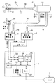
図6に示す第3の実施の形態の超音波診断装置1Cは、生体内に挿入される超音波プローブ2と、この超音波プローブ2が接続され、超音波プローブ2に内蔵された超音波振動子を駆動及び、信号処理等を行う超音波観測装置3と、この超音波観測装置3と接続され、超音波画像の表示を行う観測モニタ4と、超音波観測装置3と接続され、画像処理を行う超音波画像処理装置6と、この超音波画像処理装置6と接続され、超音波画像の表示を行うモニタ7と、超音波プローブ2が接続され、超音波プローブ2の所定位置を検出する位置算出装置8とから構成される。
【0050】
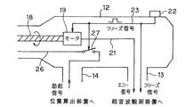
図7に示すように超音波プローブ2の操作部12内のフレキシブルシャフト18の後端が接続されるモータ19の回転軸にはギヤ41が取り付けられ、このギヤ41に噛合するギヤ42はロータリエンコーダ43の回転軸に接続されており、ロータリエンコーダ43はモータ19の回転を検出して、回転信号を出力する。
【0051】
この回転信号は信号線44を介して(図6に示すように)コード13の末端のコネクタ15が接続される超音波観測装置3と、コード14の末端のコネクタ16が接続される位置算出装置8とに伝達される。
【0052】
超音波観測装置3ではこの回転信号に同期して、メモリへの画像データの記憶等の処理を行うと共に、この回転信号を超音波観測装置3からさらに超音波画像処理装置6に伝達する。
【0053】
図8に示すように、位置算出装置8では回転信号により発振器28に接続されたスイッチ27の開閉を制御する。より、具体的には、回転信号により、スイッチ27をOFFからONする。図8の位置算出装置8は図3の位置算出装置8において、スイッチ27がフリーズ信号でなく、回転信号で開閉される構成になっている。
【0054】
また、図6に示すように超音波画像処理装置6では回転信号により超音波観測装置3からの画像データ及び位置算出装置8からの位置データが入力されるバッファ34の入力端に設けたスイッチ38の開閉を制御する。より、具体的には、回転信号により、スイッチ38をOFFからONする。
【0055】
その他の構成は第1の実施の形態と同様の構成であり、同じ構成要素には同じ符号を付け、その説明を省略する。
【0056】
次に本実施の形態の作用を説明する。
超音波振動子17は、モータ19、フレキシブルシャフト18の回転によって生体内のラジアルスキャンを行う。
【0057】
ロータリエンコーダ43の回転軸は、モータ19の回転軸とギヤ42、41を介して連動して回転する。そして、ロータリーエンコーダ43は、例えば、モータの1回転する毎にクロック状の回転信号を位置算出装置8と超音波観測装置3に送信する。
【0058】
位置算出装置8は、回転信号の入力があったときにスイッチ27をONにして励起信号を磁場発生器24に送信する。
そして、磁場発生器24は、位置算出装置8からの交流の励起信号により磁場を発生する。
【0059】
磁場発生器24の発生する磁場は磁場検出器29で検出され、位置信号を生成する。
この位置信号は、位置信号算出装置8内の位置算出回路31で超音波プローブ2の先端の位置と配向を示すデジタルの位置データに変換され、超音波画像処理装置6に送信される。
【0060】
また、超音波振動子17からのエコー信号は、超音波観測装置3で信号処理され、デジタルの画像データに変換され、超音波画像処理装置6に送信される。
【0061】
1画像分、すなわちラジアルスキャン1回分の画像データは、回転信号の入力があったときに、バッファ34に入力し記憶される。
【0062】
超音波画像処理装置6内のCPU32は、バッファ34に記憶された画像データに対応した3Dメモリ35のアドレスに格納する。こうして、ラジアルスキャンを行いながら、使用者が超音波プローブ2の先端の位置や角度を少しずつ変えることで超音波3次元画像データが構成され、3Dメモリ35に記憶される。
【0063】
画像処理回路36は、3Dメモリ35内の超音波3次元画像データより超音波3次元画像を作成し、超音波3次元画像は表示回路37にてD/A変換等の処理を経てモニタ7に表示される。この処理は特願平09−283915号等、公知の方法で行う。
【0064】
本実施の形態は以下の効果を有する。
位置算出装置8は、ロータリエンコーダ43からの回転信号の入力があったときのみ、磁場発生器24を駆動するので、位置検出が不必要なときに、磁気発生器24を駆動することがなく位置検出系の電力供給効率が向上する。
【0065】
また、磁場は磁場発生器24周囲の磁性体や導電体の配置に敏感に変化するため、例えばフレキシブルシャフト18が導電体等を含んで構成されているようなときに、上記のような構成にすると、いつもフレキシブルシャフト18が同じ回転角度になったときに磁場発生器24が磁場を発生するため、磁場のゆらぎが少なく、位置データをいつもほぼ同じ条件で取得することができる。
【0066】
本実施の形態では、回転信号に同期させ、モータ19の一回転につきスイッチ27、38を一回開閉するように構成したが、例えば信号線44の途中でロータリエンコーダ43の出力の直近に、回転信号のクロックを計数し適当なカウント値でクロックを出力するカウンタを設け、スイッチ27、38の開閉をこのクロックに同期させるように構成しても良いことは勿論である。
【0067】
このように構成することによって、スイッチの開閉動作を数回転につき一回行うよう間引くことができる。モータ19の回転は使用者が超音波プローブ2の先端の位置や角度を変える速度より速いため、本当に必要な画像データや位置データを適当な間隔で得ることができる。また、バッファ34や3Dメモリ35の容量の節約にもなる。
【0068】
(変形例)
超音波3次元画像処理を行う場合のみについて説明したが、特開昭62−68442号公報のように、モニタのボディーマーク上にプローブの位置、配向を重畳表示させるような応用例に本実施の形態の構成を適用しても良い。
【0069】
(第4の実施の形態)
次に本発明の第4の実施の形態を図9及び図10を参照して説明する。図9は本発明の第4の実施の形態の超音波診断装置の全体構成を示し、図10は3Dメモリの構造を示す。
【0070】
図9に示す第4の実施の形態の超音波診断装置1Dは図6の超音波診断装置1Cにおいて、さらに周期性体動を検出する手段を設け、この手段により生成されたゲート信号に同期して超音波3次元画像データの構築を行うようにするものである。
【0071】
具体的には、この超音波診断装置1Dでは、周期性体動として例えば心電波形を検出する電極51と、この電極51により検出された体動信号は位相検出装置52に入力され、体動信号における所定の位相を検出するとパルス状のゲート信号を発生し、このゲート信号は超音波画像処理装置6のスイッチ38をOFFからONに開閉制御するようにしている。
【0072】
なお、本実施の形態では、磁場発生器24への励起信号のON/OFFを(図6の超音波診断装置1Cで行っていた)回転信号で制御しないで、常時磁場発生器24へ励起信号を印加している。その他の構成は第3の実施の形態と同様である。
【0073】
次に本実施の形態の作用を説明する。
(a)超音波振動子17からのエコー信号は超音波観測装置3でデジタルの画像データに変換され、超音波画像処理装置6に送信される。
【0074】
(b)磁場発生器24は、位置算出装置8からの励起信号により磁場を発生する。磁場検出器29は、磁場発生器24が発生する磁場を検出し、位置信号を生成する。この位置信号は、位置算出装置8内の位置算出回路31で超音波プローブ2の先端の位置と配向を示すデジタルの位置データに変換され、超音波画像処理装置6に送信される。
【0075】
(c)電極51からの例えば生体の心電等の周期性の信号は、体動信号として、位相検出装置52に入力し、その位相が検出される。
(d)この位相検出装置52は、特定の位相の時にのみ、ゲート信号を超音波画像処理装置6に送信する。
【0076】
超音波画像処理装置6内のスイッチ38はゲート信号が入力したときのみ閉じるため、特定の体動位相の画像データ、位置データがバッファ34に記憶される。
(e)CPU32は、バッファ34に記憶された画像データを、位置データに対応して図10に示すように3次元的にメモリを配置したような構成にした3Dメモリ35のアドレスに格納する。
【0077】
これらの(a)〜(e)の動作を繰り返すことで、超音波3次元画像データが構成され、3Dメモリ35に記憶される。
(f)画像処理回路36は3Dメモリ35内の超音波3次元画像データより超音波3次元画像を作成し、表示回路37にてD/A変換等の処理を経て、モニタ7に表示される。処理は、特願平09−283915号等、公知の方法で行う。
【0078】
本実施の形態では、特定の体動位相のみを選択して、超音波3次元画像データを構成したため、歪みのない正確な超音波3次元画像データを抽出される。従って、歪みの少ない超音波3次元画像を表示できる。
【0079】
なお、上述した各実施の形態等を変形したり、部分的に組み合わせる等して構成される実施の形態等も本発明に属する。
例えば第1の実施の形態と第3の実施の形態とを組み合わせて、フリーズ・レリーズスイッチ22が操作された場合のフリーズ信号と回転信号との論理積(フリーズ信号と回転信号とをアンド回路を通して得る)得るような信号で、スイッチ27、38をOFFからONにするようにしても良い。
【0080】
より具体的に説明すると、通常はスイッチ27、38はOFFとし、フリーズ・レリーズスイッチ22が操作された場合にフリーズ信号を発生し、さらにこのフリーズ信号中における回転信号が出力されるタイミングの信号(以下、タイミング信号という)により、モータ19の回転の停止、フリーズ画の生成(メモリの書き込み一時禁止)、スイッチ27、38のOFFからONを行うようにしても良い。
【0081】
このようにすると、使用者がフリーズ画の表示或いは記録の指示を行った操作時に、その操作時におけるいつも同じ回転状態になったタイミングで磁場を発生するので、磁場の発生条件を揃えることができ、より精度が高い位置検出を行うことができる。また、省電力で位置検出を行うことができる。
【0082】
また、例えば第1の実施の形態と第4の実施の形態とを組み合わせて、フリーズ・レリーズスイッチ22が操作された場合のフリーズ信号と周期性体動信号の位相検出装置52の出力信号との論理積を得るような信号で、スイッチ27、38をOFFからONにするようにしても良い。
【0083】
より具体的に説明すると、通常はスイッチ27、38はOFFとし、フリーズ・レリーズスイッチ22が操作された場合にフリーズ信号を発生し、さらにこのフリーズ信号中における位相検出装置52により心電波形が特定の位相に達したタイミングの信号(以下、タイミング信号という)により、モータ19の回転の停止、フリーズ画の生成(メモリの書き込み一時禁止)、スイッチ27、38のOFFからONを行うようにしても良い。この場合、位相検出装置52により検出する特定の位相は例えば心電波形の変化が小さい位相或いは波形変化がほぼ停止して動き始めるタイミングの位相等を検出する。
【0084】
このようにすると、使用者がフリーズ画の表示或いは記録の指示を行った操作時に、その操作時における体動が小さい時或いは殆ど停止して体動が動く直前に得られた画像をフリーズすると共に、磁場を発生させるので、得られる超音波画像データは体動の影響の少ない画質が良いフリーズ画の表示とか、3次元超音波画像を得ることができる。また、省電力で位置検出系を形成できる。
【0085】
[付記]
1.超音波によるスキャンを行い生体の超音波画像を得る超音波プローブと、空間に磁場を張る磁場発生手段と、該磁場を検出する磁場検出手段と、検出した該磁場から前記超音波プローブの位置を算出し、位置データを得る位置算出手段と、前記磁場発生手段を駆動する駆動手段と、を有する超音波診断装置において、前記駆動手段を超音波画像の静止または記録を指示する指示信号及び前記スキャンに同期したスキャン信号との少なくとも一方に同期して磁場発生手段を駆動することを特徴とする超音波診断装置。
【0086】
2.付記1において、前記駆動手段は前記指示信号及びスキャン信号の論理積の信号で駆動する。
3.付記1において、前記駆動手段は前記指示信号及び生体が行う周期性体動の特定の位相を検出した信号の論理積の信号で駆動する。
【0087】
4.超音波によるスキャンを行い生体の超音波画像を得る超音波プローブと、該超音波画像の静止または記録を指示する入力手段と、空間に磁場を張る磁場発生手段と、該磁場を検出する磁場検出手段と、検出した該磁場から前記超音波プローブの位置を算出し、位置データを得る位置算出手段と、前記磁場発生手段を駆動する駆動手段と、を設けた超音波診断装置において、
前記駆動手段が、前記入力手段の入力に同期して磁場発生手段を駆動したことを特徴とする超音波診断装置。
【0088】
5.超音波によるスキャンを行い生体の超音波画像を得る超音波プローブと、該スキャンを1回行うごとにスキャン信号を生成するスキャン信号生成手段と、空間に磁場を張る磁場発生手段と、該磁場を検出する磁場検出手段と、検出した該磁場から前記超音波プローブの位置を算出し、位置データを得る位置算出手段と、前記磁場発生手段を駆動する駆動手段と、を設けた超音波診断装置において、
前記駆動手段が、該スキャン信号に同期して磁場発生手段を駆動したことを特徴とする超音波診断装置。
【0089】
6.生体に超音波を送受波して生体の連続した複数の超音波画像データを得る超音波プローブと、前記超音波プローブの位置を検出し、位置データを作成する位置検出手段と、該超音波画像データと、該位置データとを記憶し、超音波3次元画像データを構成するデータ構成手段と、を設けた超音波診断装置において、
前記データ構成手段が、生体が行う周期性体動の特定の位相のデータのみから該超音波3次元画像データを構成することを特徴とする超音波診断装置。
7.付記6において、前記周期性体動が心電であること。
【0090】
【発明の効果】
以上説明したように本発明によれば、超音波によるスキャンを行い生体の超音波画像を得る超音波プローブと、空間に磁場を張る磁場発生手段と、該磁場を検出する磁場検出手段と、検出した該磁場から前記超音波プローブの位置を算出し、位置データを得る位置算出手段と、前記磁場発生手段を駆動する駆動手段と、を有する超音波診断装置において、
前記駆動手段を超音波画像の静止または記録を指示する指示信号及び前記スキャンに同期したスキャン信号との少なくとも一方に同期して磁場発生手段を駆動するようにしているので、磁場発生手段を常時駆動する場合よりも電力消費を少なくできる。
【図面の簡単な説明】
【図1】本発明の第1の実施の形態の超音波診断装置の全体構成を示す図。
【図2】超音波プローブの操作部の構成を示す図。
【図3】位置検出装置の構成を示す図。
【図4】本発明の第2の実施の形態における超音波プローブの操作部の構成を示す図。
【図5】位置検出装置の構成を示す図。
【図6】本発明の第3の実施の形態の超音波診断装置の全体構成を示す図。
【図7】超音波プローブの操作部の構成を示す図。
【図8】位置検出装置の構成を示す図。
【図9】本発明の第4の実施の形態の超音波診断装置の全体構成を示す図。
【図10】3Dメモリの構成図。
【符号の説明】
1A…超音波診断装置
2…超音波プローブ
3…超音波観測装置
4…観測モニタ
5…ビデオプリンタ
6…超音波画像処理装置
7…モニタ
8…位置算出装置
11…挿入部
12…操作部
13,14…コード
15,16…コネクタ
17…超音波振動子
18…フレキシブルシャフト
19…モータ
22…フリーズ・レリーズスイッチ
24…磁場発生器
25…コイル
27…スイッチ
28…発振器
29…磁場検出器
30…コイル
31…位置算出回路
32…CPU
34…バッファ
35…3Dメモリ
36…画像処理回路
37…表示回路
38…スイッチ[0001]
BACKGROUND OF THE INVENTION
The present invention relates to an ultrasonic diagnostic apparatus that performs ultrasonic scanning with an ultrasonic probe to obtain an ultrasonic tomographic image.
[0002]
[Prior art]
In recent years, an ultrasonic diagnostic apparatus that obtains an ultrasonic image by scanning an ultrasonic wave on a living body has been widely used for diagnosis of a living body.
In this case, there is one provided with a position detection function so that the position of the obtained ultrasonic image can be understood.
[0003]
For example, Japanese Patent Laid-Open No. 62-68442 discloses an external ultrasonic diagnostic apparatus in which a magnetic coil is excited as a position detector so that the position and orientation of a probe are superimposed on a body mark. Has been.
Japanese Laid-Open Patent Publication No. 6-261900 discloses a technique in which a magnetic coil is continuously excited when performing ultrasonic three-dimensional image processing.
[0004]
[Problems to be solved by the invention]
In the conventional example, since the current for exciting is unnecessarily passed, there is a disadvantage that power is wasted. In addition, there may be noise on the ultrasonic image that degrades the image quality.
[0005]
The present invention has been made in view of the above-described points, and an object thereof is to provide an ultrasonic diagnostic apparatus that enables position detection with power saving.
[0006]
[Means for Solving the Problems]
The ultrasonic diagnostic apparatus according to claim 1 comprises:An ultrasonic probe that performs ultrasonic scanning to obtain an ultrasonic image of a living body, a magnetic field generating unit that applies a magnetic field to space, a magnetic field detecting unit that detects the magnetic field, and a position of the ultrasonic probe from the detected magnetic field Position calculating means for calculating and obtaining position data; driving means for driving the magnetic field generating means;With
The driving means drives the magnetic field generating means in synchronization with at least one of an instruction signal for instructing still image recording or recording and a scan signal synchronized with the scan, so that the magnetic field generating means is always driven. Has also made it possible to reduce power consumption.
The ultrasonic diagnostic apparatus according to
The driving means drives the magnetic field generating means in synchronization with the input of the input means.
The ultrasonic diagnostic apparatus according to claim 3, an ultrasonic probe that performs an ultrasonic scan to obtain an ultrasonic image of a living body, a scan signal generation unit that generates a scan signal each time the scan is performed, and a space A magnetic field generating means for applying a magnetic field to the magnetic field; a magnetic field detecting means for detecting the magnetic field; a position calculating means for calculating a position of the ultrasonic probe from the detected magnetic field and obtaining position data; and driving the magnetic field generating means. Driving means,
The driving means drives the magnetic field generating means in synchronization with the scan signal.
[0007]
DETAILED DESCRIPTION OF THE INVENTION
Embodiments of the present invention will be described below with reference to the drawings.
(First embodiment)
1 to 3 relate to the first embodiment of the present invention, FIG. 1 shows the overall configuration of the ultrasonic diagnostic apparatus of the first embodiment of the present invention, and FIG. 2 shows the operation section of the ultrasonic probe. FIG. 3 shows the configuration of the position detection device.
[0008]
The ultrasonic diagnostic apparatus 1 according to the first embodiment of the present invention shown in FIG. 1 includes an
[0009]
The
[0010]
An
[0011]
Then, by rotating the
[0012]
The
[0013]
The reflected wave of the ultrasonically scanned ultrasonic wave is received by the
[0014]
As shown in FIG. 2, the
[0015]
Further, the ultrasonic observation apparatus 3 prohibits overwriting of image data in the memory by the freeze signal, and outputs a video signal corresponding to the freeze image to the
[0016]
Further, for example, a
[0017]
The
[0018]
Further, the
[0019]
As shown in FIG. 1, the ultrasonic
[0020]
The image data from the ultrasonic observation device 3 and the position data from the
[0021]
Then, the image data stored in the
[0022]
In this embodiment, when a freeze image (still image) is to be obtained or a freeze image record is to be obtained, a freeze signal (video) generated when the freeze /
[0023]
Next, the operation of this embodiment will be described.
First, the operation when there is no input from the freeze /
[0024]
The
[0025]
The ultrasonic wave reflected by the changing portion of the acoustic impedance is received by the
[0026]
Next, the freeze /
[0027]
In addition, the freeze signal (applied to the motor drive circuit) stops the rotation of the
[0028]
Further, this freeze signal is input to the ultrasonic observation apparatus 3, and the internal memory is set in a write-inhibited state, and image data written in the memory immediately before the write-inhibition is repeatedly read. An ultrasonic tomographic image of a still image (one ultrasonic image data obtained by a radial scan before the freeze operation) is displayed.
In the
[0029]
When the
This magnetic field is detected by the
[0030]
The position signal is converted into digital position data indicating the position of the tip of the
[0031]
The ultrasonic
[0032]
Since the
[0033]
The
[0034]
A user such as an operator repeats the ON / OFF operation of the freeze /
[0035]
The
[0036]
The present embodiment has the following effects.
Since the
[0037]
In addition, the ultrasonic image displayed on the
[0038]
In this embodiment, the
[0039]
Further, the
[0040]
In this case, the position data is also necessary, but if it takes time to calculate the position data from the position signal by the magnetic field detection of the
[0041]
(Second Embodiment)
Next, a second embodiment of the present invention will be described with reference to FIGS. FIG. 4 shows the configuration of the operation unit of the ultrasonic probe according to the second embodiment of the present invention, and FIG. 5 shows the configuration of the position calculation device.
[0042]
In the first embodiment, the
[0043]
As shown in FIG. 4, a
[0044]
As shown in FIG. 5, the
The other configuration is the same as that of the first embodiment.
[0045]
The operation of the present embodiment is the same as that of the first embodiment, except that the position (place) where the
In the present embodiment, the number of signal lines inserted through the
[0046]
(Modification)
As an application example, only the case where ultrasonic three-dimensional image processing is performed has been described. The configuration of the embodiment may be applied.
[0047]
(Third embodiment)
Next, a third embodiment of the present invention will be described with reference to FIG. 6, FIG. 7, and FIG. FIG. 6 shows the overall configuration of the ultrasonic diagnostic apparatus according to the third embodiment of the present invention, FIG. 7 shows the configuration of the operation section of the ultrasonic probe, and FIG. 8 shows the configuration of the position detection apparatus.
[0048]
In the ultrasonic diagnostic apparatus 1A shown in FIG. 1, the excitation signal is applied to the
[0049]
An ultrasonic
[0050]
As shown in FIG. 7, a
[0051]
This rotation signal is transmitted via a signal line 44 (as shown in FIG. 6) to the ultrasonic observation device 3 to which the
[0052]
The ultrasonic observation apparatus 3 performs processing such as storing image data in a memory in synchronization with the rotation signal, and transmits the rotation signal from the ultrasonic observation apparatus 3 to the ultrasonic
[0053]
As shown in FIG. 8, the
[0054]
Further, as shown in FIG. 6, in the ultrasonic
[0055]
Other configurations are the same as those in the first embodiment, and the same components are denoted by the same reference numerals and description thereof is omitted.
[0056]
Next, the operation of this embodiment will be described.
The
[0057]
The rotary shaft of the
[0058]
The
The
[0059]
The magnetic field generated by the
The position signal is converted into digital position data indicating the position and orientation of the tip of the
[0060]
The echo signal from the
[0061]
Image data for one image, that is, one radial scan, is input and stored in the
[0062]
The
[0063]
The
[0064]
The present embodiment has the following effects.
Since the
[0065]
Further, since the magnetic field changes sensitively to the arrangement of the magnetic body and conductor around the
[0066]
In the present embodiment, the
[0067]
With this configuration, the switch can be thinned out so as to be opened and closed once every several rotations. Since the rotation of the
[0068]
(Modification)
Although only the case where ultrasonic three-dimensional image processing is performed has been described, the present embodiment is applied to an application example in which the position and orientation of the probe are superimposed and displayed on the body mark of the monitor as disclosed in Japanese Patent Laid-Open No. 62-68442. You may apply the structure of a form.
[0069]
(Fourth embodiment)
Next, a fourth embodiment of the present invention will be described with reference to FIGS. FIG. 9 shows the overall configuration of an ultrasonic diagnostic apparatus according to the fourth embodiment of the present invention, and FIG. 10 shows the structure of a 3D memory.
[0070]
The ultrasonic diagnostic apparatus 1D of the fourth embodiment shown in FIG. 9 is further provided with means for detecting periodic body movements in the ultrasonic
[0071]
Specifically, in this ultrasonic diagnostic apparatus 1D, an
[0072]
In this embodiment, ON / OFF of the excitation signal to the
[0073]
Next, the operation of this embodiment will be described.
(A) The echo signal from the
[0074]
(B) The
[0075]
(C) A periodic signal such as an electrocardiogram of a living body from the
(D) The
[0076]
Since the
(E) The
[0077]
By repeating these operations (a) to (e), ultrasonic three-dimensional image data is constructed and stored in the
(F) The
[0078]
In the present embodiment, since only the specific body motion phase is selected and the ultrasonic three-dimensional image data is configured, accurate ultrasonic three-dimensional image data without distortion is extracted. Therefore, an ultrasonic three-dimensional image with little distortion can be displayed.
[0079]
Note that embodiments and the like configured by modifying or partially combining the above-described embodiments and the like also belong to the present invention.
For example, by combining the first embodiment and the third embodiment, the logical product of the freeze signal and the rotation signal when the freeze /
[0080]
More specifically, normally, the
[0081]
In this way, when the user gives an instruction to display or record a freeze image, the magnetic field is generated at the same rotational state at the time of the operation, so the conditions for generating the magnetic field can be made uniform. Therefore, position detection with higher accuracy can be performed. Further, position detection can be performed with power saving.
[0082]
Further, for example, by combining the first embodiment and the fourth embodiment, the freeze signal when the freeze /
[0083]
More specifically, normally, the
[0084]
In this way, when the user gives an instruction to display or record a freeze image, when the body movement during the operation is small or almost stopped, the image obtained immediately before the body movement is frozen and Since the magnetic field is generated, the obtained ultrasonic image data can be displayed as a freeze image with good image quality with little influence of body movement, or a three-dimensional ultrasonic image can be obtained. Further, the position detection system can be formed with power saving.
[0085]
[Appendix]
1. An ultrasonic probe that performs ultrasonic scanning to obtain an ultrasonic image of a living body, a magnetic field generating unit that applies a magnetic field to space, a magnetic field detecting unit that detects the magnetic field, and a position of the ultrasonic probe from the detected magnetic field In an ultrasonic diagnostic apparatus having position calculation means for calculating and obtaining position data, and drive means for driving the magnetic field generation means, the drive means instructs the stationary signal to record or record an ultrasonic image and the scan An ultrasonic diagnostic apparatus, wherein the magnetic field generating means is driven in synchronism with at least one of the scan signal synchronized with.
[0086]
2. In Supplementary Note 1, the driving means is driven by a logical product of the instruction signal and the scan signal.
3. In Supplementary Note 1, the driving means is driven by a logical product of the instruction signal and a signal obtained by detecting a specific phase of the periodic body movement performed by the living body.
[0087]
4). An ultrasonic probe that scans with an ultrasonic wave to obtain an ultrasonic image of a living body, an input unit that instructs the stationary or recording of the ultrasonic image, a magnetic field generation unit that stretches a magnetic field in space, and a magnetic field detection that detects the magnetic field In the ultrasonic diagnostic apparatus, comprising: a means; a position calculating means for calculating the position of the ultrasonic probe from the detected magnetic field; and obtaining position data; and a driving means for driving the magnetic field generating means.
The ultrasonic diagnostic apparatus, wherein the driving means drives the magnetic field generating means in synchronization with the input of the input means.
[0088]
5). An ultrasonic probe that performs ultrasonic scanning to obtain an ultrasonic image of a living body, a scan signal generation unit that generates a scan signal each time the scan is performed, a magnetic field generation unit that applies a magnetic field to space, and the magnetic field In an ultrasonic diagnostic apparatus provided with a magnetic field detection means for detecting, a position calculation means for calculating the position of the ultrasonic probe from the detected magnetic field and obtaining position data, and a drive means for driving the magnetic field generation means ,
An ultrasonic diagnostic apparatus, wherein the driving means drives a magnetic field generating means in synchronization with the scan signal.
[0089]
6). An ultrasonic probe for transmitting and receiving ultrasonic waves to a living body to obtain a plurality of continuous ultrasonic image data of the living body, a position detecting means for detecting the position of the ultrasonic probe and creating position data, and the ultrasonic image In an ultrasonic diagnostic apparatus provided with data and data configuration means for storing the position data and configuring ultrasonic three-dimensional image data,
The ultrasonic diagnostic apparatus, wherein the data composing means constructs the ultrasonic three-dimensional image data only from data of a specific phase of periodic body movement performed by a living body.
7). In
[0090]
【The invention's effect】
As described above, according to the present invention, an ultrasonic probe that scans with ultrasonic waves to obtain an ultrasonic image of a living body, a magnetic field generation unit that applies a magnetic field to space, a magnetic field detection unit that detects the magnetic field, and a detection In the ultrasonic diagnostic apparatus comprising: a position calculating unit that calculates the position of the ultrasonic probe from the magnetic field and obtaining position data; and a driving unit that drives the magnetic field generating unit.
The drive means is driven in synchronism with at least one of an instruction signal for instructing stationary or recording of an ultrasonic image and a scan signal synchronized with the scan, so that the magnetic field generation means is always driven. The power consumption can be reduced compared to the case of doing so.
[Brief description of the drawings]
FIG. 1 is a diagram showing an overall configuration of an ultrasonic diagnostic apparatus according to a first embodiment of the present invention.
FIG. 2 is a diagram illustrating a configuration of an operation unit of an ultrasonic probe.
FIG. 3 is a diagram illustrating a configuration of a position detection device.
FIG. 4 is a diagram illustrating a configuration of an operation unit of an ultrasonic probe according to a second embodiment of the present invention.
FIG. 5 is a diagram illustrating a configuration of a position detection device.
FIG. 6 is a diagram showing an overall configuration of an ultrasonic diagnostic apparatus according to a third embodiment of the present invention.
FIG. 7 is a diagram illustrating a configuration of an operation unit of the ultrasonic probe.
FIG. 8 is a diagram illustrating a configuration of a position detection device.
FIG. 9 is a diagram showing an overall configuration of an ultrasonic diagnostic apparatus according to a fourth embodiment of the present invention.
FIG. 10 is a configuration diagram of a 3D memory.
[Explanation of symbols]
1A ... Ultrasonic diagnostic equipment
2 ... Ultrasonic probe
3. Ultrasonic observation equipment
4 ... Observation monitor
5 ... Video printer
6 ... Ultrasonic image processing device
7 ... Monitor
8 ... Position calculation device
11 ... Insertion part
12 ... operation part
13, 14 ... code
15, 16 ... Connector
17 ... Ultrasonic transducer
18 ... Flexible shaft
19 ... Motor
22 ... Freeze release switch
24 ... Magnetic field generator
25 ... Coil
27 ... Switch
28 ... Oscillator
29 ... Magnetic field detector
30 ... Coil
31 ... Position calculation circuit
32 ... CPU
34 ... Buffer
35 ... 3D memory
36. Image processing circuit
37 ... Display circuit
38 ... Switch
Claims (3)
前記駆動手段は超音波画像の静止または記録を指示する指示信号及び前記スキャンに同期したスキャン信号との少なくとも一方に同期して磁場発生手段を駆動することを特徴とする超音波診断装置。An ultrasonic probe that performs ultrasonic scanning and obtains an ultrasonic image of a living body, a magnetic field generating means for applying a magnetic field to space, a magnetic field detecting means for detecting the magnetic field, and a position of the ultrasonic probe from the detected magnetic field A position calculating means for calculating and obtaining position data; and a driving means for driving the magnetic field generating means ,
The ultrasonic diagnostic apparatus characterized in that the driving means drives the magnetic field generating means in synchronization with at least one of an instruction signal for instructing still image recording or recording and a scan signal synchronized with the scan.
前記駆動手段が、前記入力手段の入力に同期して磁場発生手段を駆動したことを特徴とする超音波診断装置。The ultrasonic diagnostic apparatus, wherein the driving means drives the magnetic field generating means in synchronization with the input of the input means.
前記駆動手段が、該スキャン信号に同期して磁場発生手段を駆動したことを特徴とする超音波診断装置。An ultrasonic diagnostic apparatus, wherein the driving means drives a magnetic field generating means in synchronization with the scan signal.
Priority Applications (1)
| Application Number | Priority Date | Filing Date | Title |
|---|---|---|---|
| JP19764398A JP3776597B2 (en) | 1998-07-13 | 1998-07-13 | Ultrasonic diagnostic equipment |
Applications Claiming Priority (1)
| Application Number | Priority Date | Filing Date | Title |
|---|---|---|---|
| JP19764398A JP3776597B2 (en) | 1998-07-13 | 1998-07-13 | Ultrasonic diagnostic equipment |
Publications (3)
| Publication Number | Publication Date |
|---|---|
| JP2000023979A JP2000023979A (en) | 2000-01-25 |
| JP2000023979A5 JP2000023979A5 (en) | 2005-05-12 |
| JP3776597B2 true JP3776597B2 (en) | 2006-05-17 |
Family
ID=16377911
Family Applications (1)
| Application Number | Title | Priority Date | Filing Date |
|---|---|---|---|
| JP19764398A Expired - Lifetime JP3776597B2 (en) | 1998-07-13 | 1998-07-13 | Ultrasonic diagnostic equipment |
Country Status (1)
| Country | Link |
|---|---|
| JP (1) | JP3776597B2 (en) |
Families Citing this family (7)
| Publication number | Priority date | Publication date | Assignee | Title |
|---|---|---|---|---|
| JP2004113629A (en) * | 2002-09-27 | 2004-04-15 | Olympus Corp | Ultrasonograph |
| US7775977B2 (en) | 2002-09-27 | 2010-08-17 | Olympus Corporation | Ultrasonic tomographic diagnostic apparatus |
| JP4537756B2 (en) * | 2004-04-30 | 2010-09-08 | オリンパス株式会社 | Ultrasonic diagnostic equipment |
| US20060253024A1 (en) * | 2005-04-26 | 2006-11-09 | Altmann Andres C | Software product for three-dimensional cardiac imaging using ultrasound contour reconstruction |
| US8320711B2 (en) * | 2007-12-05 | 2012-11-27 | Biosense Webster, Inc. | Anatomical modeling from a 3-D image and a surface mapping |
| US11911144B2 (en) | 2017-08-22 | 2024-02-27 | C. R. Bard, Inc. | Ultrasound imaging system and interventional medical device for use therewith |
| WO2019040045A1 (en) * | 2017-08-22 | 2019-02-28 | C.R. Bard, Inc. | Ultrasound imaging probe for use in an ultrasound imaging system |
-
1998
- 1998-07-13 JP JP19764398A patent/JP3776597B2/en not_active Expired - Lifetime
Also Published As
| Publication number | Publication date |
|---|---|
| JP2000023979A (en) | 2000-01-25 |
Similar Documents
| Publication | Publication Date | Title |
|---|---|---|
| JP5281737B2 (en) | Ultrasonic observation device and ultrasonic diagnostic device | |
| JPH0739547A (en) | Apparatus for radial ultrasonic scanning | |
| WO2006062042A1 (en) | Ultrasonic observation apparatus | |
| JPH08510654A (en) | Anterior autopsy imaging catheter | |
| JP2004113629A (en) | Ultrasonograph | |
| JP3776597B2 (en) | Ultrasonic diagnostic equipment | |
| WO2008041323A1 (en) | Ultrasonic image processing device, and ultrasonic diagnosing device | |
| JPS6047848B2 (en) | Endoscopic ultrasound diagnostic equipment | |
| WO2010050555A1 (en) | Ultrasonic wave observation device | |
| EP1040789B1 (en) | Ultrasonic diagnostic apparatus capable of functional addition | |
| JP2001333902A (en) | Ultrasonic diagnostic device | |
| JP2849131B2 (en) | Ultrasound diagnostic medical capsule | |
| JP2004129697A (en) | Ultrasonic search unit | |
| JPH10118070A (en) | Ultrasonograph | |
| JP2007037564A (en) | Ultrasonograph | |
| JP2001198125A (en) | Image diagnostic device | |
| JP3645048B2 (en) | Ultrasonic diagnostic equipment | |
| JP4474608B2 (en) | Ultrasonic diagnostic equipment | |
| JPH07136171A (en) | Ultrasonic diagnostic system | |
| JPH0856948A (en) | Ultrasonic diagnostic system | |
| JP3340500B2 (en) | Ultrasound 3D diagnostic equipment | |
| JPH11113912A (en) | Ultrasonograph | |
| JP2974250B2 (en) | Ultrasonic diagnostic device in body cavity | |
| JP3379297B2 (en) | Ultrasonic inspection equipment | |
| JP2007037844A (en) | Ultrasonic image processor |
Legal Events
| Date | Code | Title | Description |
|---|---|---|---|
| A521 | Written amendment |
Free format text: JAPANESE INTERMEDIATE CODE: A523 Effective date: 20040630 |
|
| A621 | Written request for application examination |
Free format text: JAPANESE INTERMEDIATE CODE: A621 Effective date: 20040630 |
|
| A977 | Report on retrieval |
Free format text: JAPANESE INTERMEDIATE CODE: A971007 Effective date: 20060207 |
|
| TRDD | Decision of grant or rejection written | ||
| A01 | Written decision to grant a patent or to grant a registration (utility model) |
Free format text: JAPANESE INTERMEDIATE CODE: A01 Effective date: 20060221 |
|
| A61 | First payment of annual fees (during grant procedure) |
Free format text: JAPANESE INTERMEDIATE CODE: A61 Effective date: 20060223 |
|
| FPAY | Renewal fee payment (event date is renewal date of database) |
Free format text: PAYMENT UNTIL: 20090303 Year of fee payment: 3 |
|
| FPAY | Renewal fee payment (event date is renewal date of database) |
Free format text: PAYMENT UNTIL: 20100303 Year of fee payment: 4 |
|
| FPAY | Renewal fee payment (event date is renewal date of database) |
Free format text: PAYMENT UNTIL: 20110303 Year of fee payment: 5 |
|
| FPAY | Renewal fee payment (event date is renewal date of database) |
Free format text: PAYMENT UNTIL: 20110303 Year of fee payment: 5 |
|
| FPAY | Renewal fee payment (event date is renewal date of database) |
Free format text: PAYMENT UNTIL: 20120303 Year of fee payment: 6 |
|
| FPAY | Renewal fee payment (event date is renewal date of database) |
Free format text: PAYMENT UNTIL: 20120303 Year of fee payment: 6 |
|
| FPAY | Renewal fee payment (event date is renewal date of database) |
Free format text: PAYMENT UNTIL: 20130303 Year of fee payment: 7 |