EP1543411B1 - Processeur comprenant des donnees explicites sur les informations a sauvegarder en cas de branchements vers un sous-programme - Google Patents
Processeur comprenant des donnees explicites sur les informations a sauvegarder en cas de branchements vers un sous-programme Download PDFInfo
- Publication number
- EP1543411B1 EP1543411B1 EP03808264A EP03808264A EP1543411B1 EP 1543411 B1 EP1543411 B1 EP 1543411B1 EP 03808264 A EP03808264 A EP 03808264A EP 03808264 A EP03808264 A EP 03808264A EP 1543411 B1 EP1543411 B1 EP 1543411B1
- Authority
- EP
- European Patent Office
- Prior art keywords
- program
- command
- sub
- memory locations
- information
- Prior art date
- Legal status (The legal status is an assumption and is not a legal conclusion. Google has not performed a legal analysis and makes no representation as to the accuracy of the status listed.)
- Expired - Fee Related
Links
- 238000000034 method Methods 0.000 claims description 6
- 239000000284 extract Substances 0.000 claims description 4
- 238000004590 computer program Methods 0.000 claims description 3
- 230000004044 response Effects 0.000 claims 2
- 238000000605 extraction Methods 0.000 claims 1
- 230000005540 biological transmission Effects 0.000 description 3
- 230000006870 function Effects 0.000 description 3
- 238000007726 management method Methods 0.000 description 3
- 238000013459 approach Methods 0.000 description 2
- 238000013500 data storage Methods 0.000 description 2
- 238000001514 detection method Methods 0.000 description 2
- 238000010586 diagram Methods 0.000 description 2
- 238000005457 optimization Methods 0.000 description 2
- 230000008520 organization Effects 0.000 description 2
- 230000008569 process Effects 0.000 description 2
- 230000008901 benefit Effects 0.000 description 1
- 238000004364 calculation method Methods 0.000 description 1
- 238000004883 computer application Methods 0.000 description 1
- 238000005516 engineering process Methods 0.000 description 1
- 230000002093 peripheral effect Effects 0.000 description 1
- 230000009467 reduction Effects 0.000 description 1
- 230000003252 repetitive effect Effects 0.000 description 1
Images


Classifications
-
- G—PHYSICS
- G06—COMPUTING; CALCULATING OR COUNTING
- G06F—ELECTRIC DIGITAL DATA PROCESSING
- G06F9/00—Arrangements for program control, e.g. control units
- G06F9/06—Arrangements for program control, e.g. control units using stored programs, i.e. using an internal store of processing equipment to receive or retain programs
- G06F9/30—Arrangements for executing machine instructions, e.g. instruction decode
- G06F9/30003—Arrangements for executing specific machine instructions
- G06F9/3005—Arrangements for executing specific machine instructions to perform operations for flow control
- G06F9/30054—Unconditional branch instructions
-
- G—PHYSICS
- G11—INFORMATION STORAGE
- G11C—STATIC STORES
- G11C8/00—Arrangements for selecting an address in a digital store
-
- G—PHYSICS
- G06—COMPUTING; CALCULATING OR COUNTING
- G06F—ELECTRIC DIGITAL DATA PROCESSING
- G06F9/00—Arrangements for program control, e.g. control units
- G06F9/06—Arrangements for program control, e.g. control units using stored programs, i.e. using an internal store of processing equipment to receive or retain programs
- G06F9/30—Arrangements for executing machine instructions, e.g. instruction decode
- G06F9/30098—Register arrangements
- G06F9/3012—Organisation of register space, e.g. banked or distributed register file
- G06F9/30134—Register stacks; shift registers
-
- G—PHYSICS
- G06—COMPUTING; CALCULATING OR COUNTING
- G06F—ELECTRIC DIGITAL DATA PROCESSING
- G06F9/00—Arrangements for program control, e.g. control units
- G06F9/06—Arrangements for program control, e.g. control units using stored programs, i.e. using an internal store of processing equipment to receive or retain programs
- G06F9/30—Arrangements for executing machine instructions, e.g. instruction decode
- G06F9/30145—Instruction analysis, e.g. decoding, instruction word fields
-
- G—PHYSICS
- G06—COMPUTING; CALCULATING OR COUNTING
- G06F—ELECTRIC DIGITAL DATA PROCESSING
- G06F9/00—Arrangements for program control, e.g. control units
- G06F9/06—Arrangements for program control, e.g. control units using stored programs, i.e. using an internal store of processing equipment to receive or retain programs
- G06F9/30—Arrangements for executing machine instructions, e.g. instruction decode
- G06F9/38—Concurrent instruction execution, e.g. pipeline or look ahead
- G06F9/3802—Instruction prefetching
- G06F9/3804—Instruction prefetching for branches, e.g. hedging, branch folding
- G06F9/3806—Instruction prefetching for branches, e.g. hedging, branch folding using address prediction, e.g. return stack, branch history buffer
-
- G—PHYSICS
- G06—COMPUTING; CALCULATING OR COUNTING
- G06F—ELECTRIC DIGITAL DATA PROCESSING
- G06F9/00—Arrangements for program control, e.g. control units
- G06F9/06—Arrangements for program control, e.g. control units using stored programs, i.e. using an internal store of processing equipment to receive or retain programs
- G06F9/44—Arrangements for executing specific programs
- G06F9/448—Execution paradigms, e.g. implementations of programming paradigms
- G06F9/4482—Procedural
- G06F9/4484—Executing subprograms
Definitions
- the present invention relates to processors in general, and more particularly to the management of intermediate results in leaps into a subroutine.
- processors The operation of processors is controlled by programs consisting of several instructions.
- the processor processes the program linearly from start to finish in accordance with a predetermined execution order without repeatedly executing program parts.
- the program is stored or arranged linearly in the physical memory or, in the case of a virtual memory addressing, in the virtual address space.
- the processor During execution of the program, the processor generates intermediate results which it writes into internal registers of the processor.
- these internal registers are faster writable or readable than those available to the processor
- external storage such as RAM or EEPROM is very limited in its storage capacity because it is expensive. In order to really allow full access to the fast internal memory of the processor during execution of the subroutine, it must be ensured when programming the program that those intermediate results in the internal registers still needed in the parent or main program after the subroutine has been executed , do not get lost by overwriting these internal registers during execution of the subroutine.
- a first and at the same time simplest way of saving intermediate results in the internal registers during the duration of a subprogram is to provide in the program code in execution order before the corresponding program branch instruction or the jump instruction memory instructions, which register the register contents in order, register by register, to save in a safe overwrite memory location, such as into an external RAM.
- An example of such a store instruction is, for example, the instruction MOV ⁇ location address>, Rx, where the usual notation is used for the instruction instructions and the address ⁇ location address> indicates the address of the location in which the register contents of the register Rx are stored should.
- An improved way to secure register contents for the duration of a subroutine is to use specialized instructions for pre-storing the register contents to be backed up, which do not store the register contents to be backed up individually, but in groups or at one time store in a backup storage provided for this purpose.
- An example of such a store instruction is, for example, a multiple-push operation, such as, for example, written in standard notation, Push ⁇ Rx, Ry, Rz ...>, whereby the register contents of the registers Rx, Ry, Rz .. . Are entered in a stack provided for this purpose.
- the overhead of command lines in the program code reduces to a single store command by combining multiple store commands, at least two command lines are required to prepare for the execution of the subroutine, namely the multi store command and the program fork command.
- a last possibility of saving register contents for the duration of a subprogram consists in an automatic recognition of the data to be backed up or register contents by logging those registers which have been described in advance of the jump command with intermediate results. According to this possibility, the register contents of the correspondingly recognized internal registers are automatically calculated "on the data to be preserved" when a branch instruction occurs, ie, saved to a stack or other backup memory that is not so much subject to the size restrictions of the internal registers.
- a return instruction in the subroutine corresponds to the branch instruction in the parent program, upon the occurrence of which processing is continued on the instruction following the subroutine jump instruction in the parent program.
- commands for restoring or restoring the data necessary for further processing of the parent program are required in accordance with the commands of the preliminary data backup in the jump instruction.
- a possibility for data restoration corresponding to the possibility first described above exists in simple loading instructions, such as e.g. MOV Rx, ⁇ backup location address>, which are equivalent to the store instructions.
- a variant corresponding to the second option uses a multiple pop command, such as a multi-drop command.
- Pop ⁇ Rx, Ry, Rz ...> whereupon one of the number of registers Rx, Ry, Rz ... corresponding number of register contents taken from the stack and entered into these registers.
- the register contents to be restored are automatically restored at the occurrence of the return instruction (such as RET) or written to the respective internal registers, the information which registers have been automatically saved and, otherwise in terms of how many register contents are to be taken from the backup memory and into which registers they are to be written, they are already stored in the backup memory together with the register contents to be saved when the "automatic jump instruction" is executed.
- the return instruction such as RET
- the present invention has for its object to provide a concept for data backup in subroutine jump instructions, which is more efficient.
- the present invention is based on the finding that a treatment of subprogram jumps that is more time-consuming and memory-less can be achieved by integrating not only the destination address but also backup information into the subroutine jump instruction as operands, which data is still required after execution of the subprogram in the mother program become. Separate commands in the program, once to save the data to be backed up and the other time for the actual jump to the subroutine, are not required, whereby both the execution time of the program and the program length can be reduced.
- the compiler or programmer can have a specific influence on the selection of the data to be backed up or the memory locations whose contents are to be saved Backing up the data to be backed up must only be “loaded” with those data which are absolutely necessary after execution of the subprogram in the mother program.
- FIG. 1 shows an exemplary embodiment of a processor and its environment according to an exemplary embodiment of the present invention, in which the inventive concept for data backup can be implemented in the case of subroutine jumps.
- the embodiment of Fig. 1 is merely exemplary in nature and is intended to aid clarity. Accordingly, although only the treatment of physical addresses is provided in the embodiment of Fig. 1, the present invention may equally be used in the context of virtual memory addressing.
- Fig. 1 shows a processor 10 with a program memory 12, e.g.
- the processor 10 includes an instruction processor 16, an instruction decoder 18, a program counter 20, and a set of internal registers 22.
- the processor 10 further includes an instruction set 24.
- the instruction decoder 18 is coupled to the program memory 12 is connected to receive therefrom the currently executing command among the instructions of the program 26 to be processed, which is stored in the program memory 12.
- the instruction decoder 18 also has knowledge of the instruction set 24.
- the instruction set 24 includes all possible instruction types or instruction operations which the processor 10 is capable of executing.
- Each instruction of program 26, and thus also the instruction currently being processed corresponds to and differs from one of the instruction operations of instruction set 24 only by the particular values of its operands which are determined in instruction operation for number, size and purpose only.
- each instruction is assigned a unique opcode, by means of which the instruction decoder 18 can distinguish each incoming instruction to be processed according to its instruction type or instruction operation.
- Each instruction operation may be assigned a different number of operands necessary to execute the instruction operation.
- the instruction decoder 18 thus requests, after receipt of the operation code of the instruction to be currently processed, as many operands of the instruction from the memory 12 as belong to the instruction currently being processed on the basis of its instruction type, whereupon the reading of the current instruction is completed.
- the instruction set 24 includes a subroutine jump instruction operation 28, which will be discussed in more detail below.
- the instruction decoder 18 is further connected to the instruction processing means 16 for notifying the instruction type of the instruction currently being processed and the operands thereof necessary for processing the same.
- the instruction decoder 18 is further connected to the program counter 20 to send an incremental signal to the program counter 20 upon receipt of the instruction currently being processed.
- the program counter 20 contains a value which always points to the program 26 or always points to the address of the instruction in the program 26 which is to be executed next according to the execution order. Because the instructions, because of their different structure, i. without or with operands having different lengths and thus occupying different numbers of address positions in the program 26, the increment signal notifies the program counter 20 of the necessary number of address increments to point to the next instruction in the program 26.
- the processing means 16 processes the instructions according to the command type and, if present, with the aid of the operands. During program execution, the processing means 16 writes among other things processor intermediate results or data into a multiple register 22, which in the present example exemplarily consists of 16 registers.
- the command processor 16 also has a bus interface 30 to a bus (not shown) through which the command processor 16 can communicate with peripheral units under the control of the program 26 commands, such as, in the case of a smart card, a crypto-coprocessor, a terminal interface or similar.
- the instruction processing means 16 is also connected to the backup stack 14 for saving the data in the register 22 during the period of execution of a subroutine, as will be explained in more detail below, in order to make available the data after execution of the subroutine to enter (Push), wherein a backup stack memory pointer, which is illustratively shown in Fig. 1 as an arrow 32, always points to the last registered date.
- processor 10 only involved the linear execution of program 26 without the occurrence of jump instructions such as those of subroutine jump instruction operation 28. If the instruction currently being processed is a true jump instruction (JMP) with the aim of continuing the execution of the program 26 by the processor 10 elsewhere, the instruction processing means 16 writes the destination address contained in the jump instruction as an operand directly into the program counter 20 so that the next instruction to be processed is read from this destination address and subsequently supplied to the instruction decoder 18.
- JMP true jump instruction
- the command processor 16 If the command currently being processed is a jump command with return property, such as the subprogram jump instruction 28 described below, with the aim of interrupting the execution of the program 26 by the processor 10 for the execution of a subprogram, the command processor 16 first places the in the program counter 20 registered address in a return address stack and then writes the destination address contained in the jump instruction in the program counter 20 so that the next instruction to be processed is read from this destination address and then supplied to the instruction decoder 18, and later upon the occurrence of a return instruction, the return address from the Stack memory can be read.
- the command processor 16 first places the in the program counter 20 registered address in a return address stack and then writes the destination address contained in the jump instruction in the program counter 20 so that the next instruction to be processed is read from this destination address and then supplied to the instruction decoder 18, and later upon the occurrence of a return instruction, the return address from the Stack memory can be read.
- subroutine jump instruction operation differs from the term "subprogram jump instruction” in that subroutine jump instruction operation indicates more the instruction definition than the other instruction definitions of the instruction operations in the instruction set of the processor, while subroutine jump instruction of an actual embodiment corresponds to the subroutine jump instruction operation in the program to be executed.
- subroutine jump instruction operation indicates more the instruction definition than the other instruction definitions of the instruction operations in the instruction set of the processor, while subroutine jump instruction of an actual embodiment corresponds to the subroutine jump instruction operation in the program to be executed.
- the value (s) of the operands are indefinite, while in an instruction, all operands are determined.
- the subroutine jump instruction indicated generally at 34 in Figure 2
- the subroutine jump instruction consists essentially of two parts, an opcode at the beginning and an operand set following it.
- the operand set again consists of a destination address field and a backup information field.
- the opcode is used to uniquely identify the subroutine jump instruction 34. This is given to the instruction decoder (18 in FIG. 1) of the processor when a instruction 34 is read out first, whereupon the instruction decoder already issues the operand set of the destination address in the destination address field and the save information in the save information field expected.
- the instruction decoder thus requests further bytes from the instruction memory until the complete instruction set of the instruction 34 is also loaded from the instruction memory.
- FIG. 3 shows an exemplary section of a program to be processed.
- the rectangular boxes indicate command lines of the program, each command line containing a command.
- the program to be processed is divided into a first part, i. the mother program, and a second part, i. the subroutine.
- the parent program is arranged linearly according to a processing order, the command lines being numbered exemplarily from i-6 to i + 4.
- the command lines i-6 to i + 4 of the parent program are stored, for example, in succession in the physical memory of the program memory.
- MMU Memory Management Unit
- the commands or command lines of the subroutine are also arranged linearly and are numbered j through j + 4 by way of example.
- the subroutine is stored elsewhere in the physical program memory.
- load load instructions which describe registers R1-R6 with contents from external memory addresses (0x ).
- FIG. 3 further shows that a return instruction (RET) is provided in the command line j + 4 of the subroutine.
- the return instruction comprises only one operation code but not one operand.
- the processor fetches the slave address of the instruction line i + 1 of the parent program following the instruction line of the subroutine jump instruction from a dedicated return stack (not shown in Fig. 1) in which, as is usual, the processor has entered the program counter value at the jump command in the command line i. From then on, execution of the program is resumed within the parent program from command line i + 1.
- register or restore actions are taken to register (R1-R3), which is indicated in the subroutine jump instruction within the backup information the mother program after execution of the subroutine in the parent program are required to secure or restore.
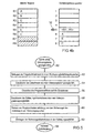
- FIGS. 4a-4d the contents of the internal registers and the save stack memory of the processor executing the program of FIG. 3 are shown by way of example in FIGS. 4a-4d.
- Figs. 4a-4d for the sake of simplicity, it is assumed that there are only eight internal registers R1-R8 and that the backup stack has eight memory locations.
- Fig. 4a exemplifies the state which occurs until the occurrence of the subroutine jump instruction in the command line i of the parent program has resulted.
- the internal registers R1-R6 have been described with contents A, B, C, a, b and c.
- the capitalization is intended to indicate that the contents are still needed after the subroutine has been executed, whereas the lowercase contents are not needed, since they represent, for example, only temporary counter values.
- the backup stack is empty.
- the subprogram jump instruction cycle shown in Fig. 5 takes place in the processor, and in the description of Fig. 5 further reference is made to Fig. 1 as appropriate.
- the subroutine jump instruction from command line i enters the instruction decoder 18 as the instruction currently being processed, it notifies the instruction processor 16 of the occurrence of a subroutine jump instruction 50.
- the instruction decoder 18 also provides the incremental signal to increment the program counter 20 according to the number of address positions. which corresponds to the length of the subprogram jump instruction.
- a step 52 the processor 10 causes the program counter value of the program counter 20 to be written into a return instruction stack (not shown in Figure 1) corresponding to the address of the next instruction to the subroutine jump instruction in the parent program, ie the address of the instruction line i + 1.
- the instruction decoder 18 extracts the destination address from the subroutine jump instruction and forwards it to the instruction processing device 16.
- the command processing device 16 sets the program counter 20 to the destination address in a step 56. This will cause the subsequent execution of the program to continue on the subroutine.
- the command decoder 18 extracts the backup information (R1-R3) from the subroutine jump command.
- R1-R3 backup information
- the backup information indicates that the register contents of the registers R1-R3 are data to be saved.
- the instruction processing means 16 saves the register contents into the register contents of the registers indicated by the backup information in the backup memory by registering the register contents of the displayed registers in the backup stack memory 14 (FIG. 1) in a predetermined order.
- the command processor 16 then enters the backup information into the backup stack. This is to ensure that the return instruction, which need not have an operand, ensures that when the register contents are reconstructed or restored, they are written back to the internal registers from which they originated.
- the backup stack includes, in the lowermost locations 6-8, the register contents of the registers R1, R2, and R3 indicated by the backup information, namely, A, B, and C, the register contents having been registered in the backup stack memory in the order of larger register number to smaller register number.
- the uppermost storage location 5 of the backup stack stores the backup information (R1-R3).
- next instruction cycle 64 which in turn starts decoding the instruction currently being processed, in this case, the instruction which is at the destination address, namely the example of FIG. 3 in the instruction line j of the subroutine.
- Fig. 4c shows the state that has set in the subroutine after execution of the subroutine until occurrence of the return instruction in the command line j + 4.
- the register contents of the internal registers R2 - R4 have been overwritten with the contents of ⁇ , ⁇ and ⁇ .
- the value ⁇ has been entered in register 8.
- the command processing means 16 reads out the last entered value as indicated by the stack memory pointer 32 from the save stack memory, namely the backup information of the last subroutine jump instruction, R1 - R3.
- the backup information is obtained from the backup information this register contents must be written.
- the backup information indicates that three register contents are to be read from the backup stack, namely A, B, and C. Further, the backup information indicates, by the convention of the record order in saving (step 60) the register contents to be backed up into the backup stack, which secure register contents into which internal registers are to be written, namely A in R1, B in R2 and C in R3.
- the resulting state is shown in Fig. 4d.
- the internal registers R1 - R3 in which intermediate results stored after the subroutine call were stored before the subroutine call when executing the parent program should have been restored or restored with respect to their register contents.
- the register contents R4 are different from those before the subroutine call, which is irrelevant since it is not needed for the further execution of the parent program (otherwise R4 would have been included in the backup information).
- the backup stack is empty again.
- Fig. 6 Shown in Fig. 6 is another embodiment of a program to be processed which merely serves to illustrate that subroutine executions may be interleaved, i. that from a called subroutine another subroutine can be called.
- the embodiment of Fig. 6 differs from that of Fig. 3 only in that it is assumed that in the command line j + 2 of the subroutine there is another subroutine jump command.
- the contents of the internal registers R1-R8 and the storage locations of the backup storage which result after execution of the jump instruction in the command line j + 2 are shown in FIG.
- the register contents of the indicated internal register R2 in the backup stack are free to the next one
- the backup information of the second subroutine jump namely R2
- R2 have been entered in the last or uppermost memory location of the backup stack, on which the stack memory pointer 32 points.
- the backup information in the subroutine jump instruction was used to uniquely identify those internal registers whose register contents were to be stored in the backup memory 14.
- the records to be backed up would always be those that did not belong to those specified.
- the backup information is associated with automatically updated logging information to indicate the register contents to be backed up.
- Fig. 8 shows the state of the internal registers R1-R8 and the backup stack as it results from execution of the program of Fig. 3 after execution of the subroutine jump instruction in line i, but using automatic recognition of used internal registers as described in Figs is described below.
- FIG Register 70 in which one flag is provided per register.
- the instruction processing means 16 is arranged to set the flag corresponding to this register each time an intermediate result in one of the internal registers R1-R8 is stored, if not already set. In the present case, as indicated by small crosses, the flags of the thus-used registers R1-R6 are set.
- the backup information of the subprogram jump instruction in the command line i does not explicitly indicate those registers which are to be backed up, but only those which are to be explicitly excluded from the backup, since they will be lost in the further execution of the parent program Processing of the subroutine are not needed, in this case the registers R4 - R8. Accordingly, the subroutine jump instruction cycle is different from that described with reference to Fig. 5 only in that in the step of entry 62, the save information itself is not stored in the save stack which indicates only the non-secure registers R4-R8, but instead the auto-detection or flags set, respectively, of registers R1-R6 minus those explicitly excluded from the backup by the backup information, namely R4-R8. In this case, as in the embodiment of Figs. 4a-4d, the registers R1-R3, i. any registers not excluded from the backup that were used before the subprogram jump command occurred.
- subroutine jump instructions which differ either by the encoding of the backup information in the backup information field (see FIG. 2) or the way they are interpreted in the command processor 16.
- a subprogram jump instruction of this kind could be written in common notation, for example as shown in FIG. 3, as "call ⁇ jumpaddress>, Rx, Ry, ", a subroutine jump instruction indicating the continuation of program execution at the destination address Backup the register contents in the registers Rx, Ry, ... has the consequence.
- the backup information of the subprogram jump command indicate the register contents to be explicitly saved or those registers whose register contents are not to be saved, as was the case with the exemplary embodiment of FIG. 8, for example.
- a possible notation for such a subprogram jump instruction would be, for example, "call ⁇ destination address>, / rx, / ry, ", a subprogram jump instruction which jumps to the destination address and saves all or in the case of automatic recognition used registers, of all internal ones used Register with the exception of the registers marked with "/".
- the backup information can consist of a mask which includes a
- the backup information can consist of a mask which includes a
- the bits associated with a register to be backed up may have a logical high state while the bits associated with the other registers may be in a logical low state.
- the bits associated with a register not to be backed up could, for example, have a logic high state while the bits associated with the other registers have a logic low state.
- the fuse information of the subprogram jump instruction of the embodiment of FIG. 3 could then be indicated, for example, by the mask "11100000” and those of the subprogram jump instruction of the embodiment of FIG. 8 through the mask of "00011111", where the first bit from the left is the register R1, the second bit from the left is assigned to the register R2 and so on.
- the backup information field of the command would be a mask different from the subroutine jump command to the subroutine jump command. This mask could serve to be placed in the backup stack (step 62).
- the backup information only has the specification of a register or of an order rank.
- the instruction processor knows that all of the higher order or higher index registers or, alternatively, all lower order and low index registers, respectively, are to be considered as explicitly indicated along with the register indicated by the backup information to be considered to be secured or not to be secured.
- the backup information indicates the register R3
- An actual encoding of the backup information would then be, for example, a four-bit binary word of "0011", i.
- the command processor excludes from registering, by convention with the specified register, any equal or higher index registers.
- the backup information could be coded by the bit word "0100", i. the binary representation of 4.
- the internal registers may also be preferable depending on the processor's usage and architecture.
- the backup information field (see FIG. 2) could be divided into two subfields, one of which contains backup information for the address registers and in which other backup information for the data registers are included.
- the coding and convention regarding the interpretation of the backup information for the two register types would be possible according to all the embodiments described above. For example, a command of call ⁇ jump_address>, D5, A13, could indicate that all data registers Dx having an index greater than or equal to 5 and all address registers having an index of 13 or greater are saved in the backup stack.
- the instruction set of the processor could either contain only a subprogram jump instruction according to the invention whose encoding and interpretation is adapted to the application of the processor. However, several subroutine jump instruction types could also be present in the instruction set, which then differ by their opcode.
- the command processing device can then decide how to interpret the backup information, that is, first, whether as a bitmask or binary index of a register index, from or to which all registers are explicitly considered specified, second, whether as an explicit indication of the secured (Fig. 4) or the register (FIG. 8) which is not to be saved, and thirdly, whether to be associated with the flags indicating the registers used (FIG. 8) or independent (FIG. 4).
- an optimal use of the backup stack storage capacity can be achieved by, for example, data required after execution of the subroutine, from the lowest index into the registers while data not needed after execution of the subroutine is written to the registers from the highest index register.
- the invention thus enables optimization of the memory requirement for the program code of a processor on the one hand and a simultaneous reduction of the need to data storage for data to be backed up using program branch instructions on the other side.
- memory locations of any type may also be the storage location of the information or data to be secured, if any.
- the backup stack could also be located in the processor itself.
- the backup stack could work differently than after the stack or basement storage principle.
- variable length coding schemes could be used to encode the registers to be explicitly specified as being secure or non-secure, respectively.
Landscapes
- Engineering & Computer Science (AREA)
- Software Systems (AREA)
- Theoretical Computer Science (AREA)
- Physics & Mathematics (AREA)
- General Engineering & Computer Science (AREA)
- General Physics & Mathematics (AREA)
- Microelectronics & Electronic Packaging (AREA)
- Executing Machine-Instructions (AREA)
- Storage Device Security (AREA)
Claims (20)
- Processeur pour exécuter un programme (26) avec des commandes, présentant un programme-mère avec une commande de saut vers un sous-programme et un sous-programme qui doit être exécuté en réponse à la commande de saut vers un sous-programme, avec
un moyen de traitement de commande (16);
un décodeur de commande (18) qui est réalisé, en cas d'occurrence de la commande de saut vers un sous-programme dans le programme-mère, de manière à
extraire de la commande de saut vers un sous-programme des informations de sauvegarde sur les données requises après l'exécution du sous-programme dans le programme-mère;
extraire de la commande de saut vers un sous-programme une adresse cible qui renvoie au sous-programme; et
communiquer au moyen de traitement de commande (16) l'occurrence de la commande de saut vers un sous-programme dans le programme-mère ainsi que les informations de sauvegarde et l'adresse cible,
le moyen de traitement de commande (16) étant réalisé, en cas d'occurrence de la commande de saut vers un sous-programme dans le programme-mère, de manière à
sauvegarder sur base des informations de sauvegarde, les données requises après l'exécution du sous-programme dans le programme-mère; et
provoquer, sur base de l'adresse cible, que l'exécution du programme soit continué par le sous-programme. - Processeur selon la revendication 1, dans lequel le processeur présente un ensemble de commandes (24) composé de plusieurs opérations de commande pouvant être identifiées de manière univoque par des codes d'opération, parmi les opérations de commande se trouvant une opération de commande de saut vers un sous-programme qui est identifiée de manière univoque par un code d'opération de commande de saut vers un sous-programme, et dans lequel chaque commande du programme présente un code d'opération par lequel cette dernière peut être associée à l'une des opérations de commande, le décodeur de commande (18) étant réalisé de manière à décoder une commande du programme-mère actuellement à exécuter, pour obtenir le code d'opération de celle-ci, et à communiquer l'occurrence de la commande de saut vers un sous-programme au moyen de traitement de commande (16) si le code d'opération de celle-ci est identique au code d'opération de commande de saut vers un sous-programme, et la commande de saut vers un sous-programme présentant, comme opérandes, l'adresse cible et les informations de sauvegarde.
- Processeur selon la revendication 2, dans lequel est chaque fois définie, parmi les commandes du programme-mère et du sous-programme, une séquence d'exécution par laquelle le processeur est réalisé de manière à effectuer l'exécution du programme, chaque commande présentant exactement un code d'opération par lequel elle peut être associée à l'une des opérations de commande.
- Processeur selon la revendication 3, dans lequel le processeur est réalisé de manière à exécuter chaque commande du programme dans l'un de cycles de commande successifs, le décodeur de commande (18) et le moyen de traitement de commande (16) étant réalisés de manière à effectuer l'extraction, la sauvegarde et le provocation en un seul cycle de commande.
- Processeur selon l'une des revendications 1 à 4, présentant, par ailleurs, la caractéristique suivante:des emplacements de mémoire (22) destinés à mémoriser des résultats intermédiaires de processeur pendant l'exécution du programme, les données requises après l'exécution du sous-programme dans le programme-mère se composant des résultats intermédiaires de processeur d'une sélection d'emplacements de mémoire, la sélection étant fonction des informations de sauvegarde.
- Processeur selon la revendication 5, dans lequel les informations de sauvegarde indiquent au moins un emplacement de mémoire (22) appartenant à la sélection, aucun autre emplacement de mémoire n'appartenant à la sélection.
- Processeur selon la revendication 5, dans lequel les informations de sauvegarde indiquent au moins un emplacement de mémoire (22) n'appartenant pas à la sélection.
- Processeur selon la revendication 7, dans lequel les autres emplacements de mémoire appartiennent à la sélection.
- Processeur selon la revendication 7, dans lequel la sélection est, en outre, fonction d'informations d'utilisation qui indiquent celui parmi les emplacements de mémoire qui a été utilisé, pendant l'exécution du programme-mère jusqu'à l'occurrence de la commande de saut vers un sous-programme, pour la mémorisation de résultats intermédiaires, de sorte que la sélection comprenne les emplacements de mémoire qui sont indiqués par les informations d'utilisation comme étant utilisés pendant l'exécution du programme-mère jusqu'à l'occurrence de la commande de saut vers un sous-programme et qui, en même temps, n'appartiennent pas aux emplacements de mémoire qui sont indiqués par les informations de sauvegarde.
- Processeur selon l'une des revendications 1 à 9, dans lequel le moyen de traitement de commande (16) est réalisé de manière à entrer, lors de la sauvegarde des données requises après l'exécution du sous-programme dans le programme-mère, les données dans une mémoire à colonne (14).
- Processeur selon la revendication 10, dans lequel le moyen de traitement de commande (16) est réalisé de manière à entreposer, lors de l'entreposage des données dans la mémoire à colonne (14), ensemble avec les données également les informations de sauvegarde.
- Processeur selon l'une des revendications 2 à 11, dans lequel le sous-programme présente une commande de saut en arrière et dans lequel l'ensemble de commandes (24) présente, par ailleurs, une opération de commande de saut en arrière qui peut être identifiée par un code d'opération de commande de saut en arrière univoque, le décodeur de commande (18) étant réalisé de manière à communiquer au moyen de traitement de commande (16), au cas où le code d'opération de la commande actuellement à exécuter coïncide avec le code d'opération de commande de saut en arrière, l'occurrence de la commande de saut en arrière, le moyen de traitement de commande (16) étant réalisé de manière à rétablir, à l'occurrence de la commande de saut en arrière, les données sauvegardées sur base des informations de sauvegarde mémorisées.
- Processeur selon l'une des revendications 1 à 12, dans lequel les informations de sauvegarde comprennent un mot binaire présentant une pluralité de bits qui sont attribués, chacun, à l'un des emplacements de mémoire (22), tous les bits qui sont attribués à des emplacements de mémoire devant être mémorisés, ou tous les bits qui sont attribués à des emplacements de mémoire ne devant pas être mémorisés, présentant un premier état logique, tandis que les autres bits présentent un deuxième état logique opposé aux premiers bits.
- Processeur selon la revendication 14, dans lequel le moyen de traitement de commande (16) est réalisé de manière à sauvegarder, lors de la sauvegarde, les résultats intermédiaires des emplacements de mémoire qui sont associés à des bits présentant le premier état logique, et à ne pas sauvegarder les résultats intermédiaires des emplacements de mémoire qui sont associés à des bits présentant le deuxième état logique ou, inversement, à ne pas sauvegarder les résultats intermédiaires des emplacements de mémoire qui sont associés à des bits présentant le premier état logique, et à sauvegarder les résultats intermédiaires des emplacements de mémoire qui sont associés à des bits présentant le deuxième état logique.
- Processeur selon l'une des revendications 5 à 12, dans lequel est défini parmi les emplacements de mémoire (22) un ordre de rang, les informations de sauvegarde indiquent un emplacement de mémoire d'un rang déterminé, et les emplacements de mémoire qui doivent être sauvegardés ou les emplacements de mémoire qui ne doivent pas être sauvegardés sont les emplacements de mémoire soit d'un rang supérieur, soit d'un rang inférieur au rang déterminé.
- Processeur selon la revendication 15, dans lequel le moyen de traitement de commande (16) est réalisé de manière à mémoriser, lors de la sauvegarde, les résultats intermédiaires des emplacements de mémoire qui sont d'un rang supérieur au rang déterminé, et à ne pas mémoriser les résultats intermédiaires des emplacements de mémoire qui sont d'un rang inférieur au rang déterminé, ou, inversement, à ne pas mémoriser les résultats intermédiaires des emplacements de mémoire qui sont d'un rang supérieur au rang déterminé, et à mémoriser les résultats intermédiaires des emplacements de mémoire qui sont d'un rang inférieur au rang déterminé.
- Processeur selon l'une des revendications 1 à 13 ou 15, présentant la caractéristique suivante:un moyen de protocolisation destiné à placer un repère pour chaque emplacement de mémoire (22), dans lequel une valeur intermédiaire a été mémorisée pendant l'exécution du programme-mère,le moyen de traitement de commande (16) est réalisé de manière à sauvegarder, lors de la sauvegarde, les résultats intermédiaires des emplacements de mémoire pour lesquels est placé un repère, sous déduction des résultats intermédiaires des emplacements de mémoire qui sont indiqués par les informations de sauvegarde.
- Processeur selon la revendication 17, dans lequel le moyen de traitement de commande est réalisé de manière à entreposer, lors de l'entreposage des données dans la mémoire à colonne, ensemble avec les données également les informations de sauvegarde.
- Procédé pour exécuter un programme avec des commandes, qui présente un programme-mère avec une commande de saut vers un sous-programme et un sous-programme devant être exécuté en réponse à la commande de saut vers un sous-programme, le procédé présentant les étapes suivantes consistant à:à l'occurrence de la commande de saut vers un sous-programme dans le programme-mère, par un décodeur de commande,
extraire de la commande de saut vers un sous-programme les informations de sauvegarde sur les données requises après l'exécution du sous-programme dans le programme-mère; et
extraire une adresse cible de la commande de saut vers un sous-programme, l'adresse cible renvoyant au sous-programme, et par un moyen de traitement de commande,
sauvegarder les données requises après l'exécution du sous-programme dans le programme-mère sur base des informations de sauvegarde; et
provoquer, sur base de l'adresse cible, que l'exécution du programme soit continué par le sous-programme. - Programme d'ordinateur avec un code de programme pour exécuter le procédé selon la revendication 19 lorsque le programme d'ordinateur est exécuté sur un ordinateur.
Applications Claiming Priority (3)
| Application Number | Priority Date | Filing Date | Title |
|---|---|---|---|
| DE10245367A DE10245367A1 (de) | 2002-09-27 | 2002-09-27 | Prozessor mit expliziter Angabe über zu sichernde Informationen bei Unterprogrammsprüngen |
| DE10245367 | 2002-09-27 | ||
| PCT/EP2003/010597 WO2004042559A2 (fr) | 2002-09-27 | 2003-09-23 | Processeur comprenant des donnees explicites sur les informations a sauvegarder en cas de branchements vers un sous-programme |
Publications (2)
| Publication Number | Publication Date |
|---|---|
| EP1543411A2 EP1543411A2 (fr) | 2005-06-22 |
| EP1543411B1 true EP1543411B1 (fr) | 2007-11-21 |
Family
ID=32009957
Family Applications (1)
| Application Number | Title | Priority Date | Filing Date |
|---|---|---|---|
| EP03808264A Expired - Fee Related EP1543411B1 (fr) | 2002-09-27 | 2003-09-23 | Processeur comprenant des donnees explicites sur les informations a sauvegarder en cas de branchements vers un sous-programme |
Country Status (6)
| Country | Link |
|---|---|
| US (1) | US7412593B2 (fr) |
| EP (1) | EP1543411B1 (fr) |
| AU (1) | AU2003301890A1 (fr) |
| DE (2) | DE10245367A1 (fr) |
| TW (1) | TWI239477B (fr) |
| WO (1) | WO2004042559A2 (fr) |
Families Citing this family (5)
| Publication number | Priority date | Publication date | Assignee | Title |
|---|---|---|---|---|
| CN102193776B (zh) * | 2010-03-10 | 2014-06-18 | 上海海尔集成电路有限公司 | 跳转指令的处理方法及微控制器 |
| KR101979732B1 (ko) * | 2012-05-04 | 2019-08-28 | 삼성전자 주식회사 | 비휘발성 메모리 컨트롤러 및 비휘발성 메모리 시스템 |
| US9489316B2 (en) * | 2013-03-15 | 2016-11-08 | Freescale Semiconductor, Inc. | Method and device implementing execute-only memory protection |
| WO2015107637A1 (fr) * | 2014-01-15 | 2015-07-23 | 三菱電機株式会社 | Appareil de commande numérique |
| US10019576B1 (en) * | 2015-04-06 | 2018-07-10 | Intelligent Automation, Inc. | Security control system for protection of multi-core processors |
Family Cites Families (9)
| Publication number | Priority date | Publication date | Assignee | Title |
|---|---|---|---|---|
| IT1192334B (it) * | 1977-10-25 | 1988-03-31 | Digital Equipment Corp | Sistema di elaborazione dei dati numerici |
| US4338663A (en) * | 1978-10-25 | 1982-07-06 | Digital Equipment Corporation | Calling instructions for a data processing system |
| US4493027A (en) * | 1981-05-22 | 1985-01-08 | Data General Corporation | Method of performing a call operation in a digital data processing system having microcode call and return operations |
| US4445173A (en) * | 1981-09-11 | 1984-04-24 | Data General Corporation | Improved system for saving and restoring state in call and return operations |
| JPH0353328A (ja) * | 1989-07-20 | 1991-03-07 | Hitachi Ltd | レジスタ退避回復方法ならびに処理装置 |
| US5325494A (en) * | 1991-06-21 | 1994-06-28 | Kabushiki Kaisha Toshiba | Computer |
| US6438740B1 (en) * | 1997-08-21 | 2002-08-20 | Compaq Information Technologies Group, L.P. | System and method for dynamically identifying free registers |
| US6212630B1 (en) * | 1997-12-10 | 2001-04-03 | Matsushita Electric Industrial Co., Ltd. | Microprocessor for overlapping stack frame allocation with saving of subroutine data into stack area |
| US6314510B1 (en) | 1999-04-14 | 2001-11-06 | Sun Microsystems, Inc. | Microprocessor with reduced context switching overhead and corresponding method |
-
2002
- 2002-09-27 DE DE10245367A patent/DE10245367A1/de not_active Ceased
-
2003
- 2003-09-22 TW TW092126123A patent/TWI239477B/zh not_active IP Right Cessation
- 2003-09-23 WO PCT/EP2003/010597 patent/WO2004042559A2/fr active IP Right Grant
- 2003-09-23 AU AU2003301890A patent/AU2003301890A1/en not_active Abandoned
- 2003-09-23 DE DE50308662T patent/DE50308662D1/de not_active Expired - Lifetime
- 2003-09-23 EP EP03808264A patent/EP1543411B1/fr not_active Expired - Fee Related
-
2005
- 2005-03-28 US US11/093,276 patent/US7412593B2/en active Active
Non-Patent Citations (1)
| Title |
|---|
| None * |
Also Published As
| Publication number | Publication date |
|---|---|
| DE10245367A1 (de) | 2004-04-15 |
| DE50308662D1 (de) | 2008-01-03 |
| AU2003301890A1 (en) | 2004-06-07 |
| WO2004042559A2 (fr) | 2004-05-21 |
| TWI239477B (en) | 2005-09-11 |
| US7412593B2 (en) | 2008-08-12 |
| WO2004042559A3 (fr) | 2005-01-13 |
| EP1543411A2 (fr) | 2005-06-22 |
| TW200409025A (en) | 2004-06-01 |
| AU2003301890A8 (en) | 2004-06-07 |
| US20050201195A1 (en) | 2005-09-15 |
Similar Documents
| Publication | Publication Date | Title |
|---|---|---|
| DE69133302T2 (de) | Registerabbildung in einem einzigen Taktzyklus | |
| DE69833008T2 (de) | Prozessor mit instruktionskodierung mittels eines schablonenfeldes | |
| DE2411963C3 (de) | Elektronische Datenverarbeitungsanlage mit einer Prioritätssteuerschaltung mit änderbaren Steuerblöcken | |
| DE2234867C2 (de) | Anordnung in einer Datenverarbeitungsanlage zum Steuern der Verarbeitung zweier voneinander unabhängiger Befehlsfolgen | |
| DE2230102A1 (de) | Rechenwerk fuer variable wortlaengen | |
| DE1499200B2 (de) | Datenverarbeitungsanlage mit vorranggesteuerter programm unterbrechung | |
| DE3131341A1 (de) | "pufferspeicherorganisation" | |
| DE2630323B2 (de) | Datenspeichereinrichtung mit einem Hauptspeicher, einem Hilfsspeicher und einer Vorausschaulogik | |
| DE2714805A1 (de) | Datenverarbeitungssystem | |
| EP1358558B1 (fr) | Circuit de microprocesseur destiné a des supports de données et procedé permettant d'organiser l'accès a des données archivées dans la mémoire | |
| DE1285219B (de) | Steuerwerk zur Ausfuehrung von Unterprogrammen | |
| DE2054830B2 (de) | Informationsverarbeitungsanlage mit mitteln zum zugriff zu speicher-datenfeldern variabler laenge | |
| DE1549531A1 (de) | Digitale Rechenanlage | |
| EP0935214B1 (fr) | Carte à puce avec circuit intégré | |
| DE1909090C3 (de) | Schutzeinrichtung für den Arbeitsspeicher einer Rechenanlage | |
| EP1639475A2 (fr) | Architecture de processeur pour identification exacte d'index | |
| DE102018202446A1 (de) | Verfahren zum Modularisieren einer Softwarearchitektur | |
| DE19824289A1 (de) | Pipelineverarbeitungsmaschine | |
| EP1543411B1 (fr) | Processeur comprenant des donnees explicites sur les informations a sauvegarder en cas de branchements vers un sous-programme | |
| EP1352318B1 (fr) | Circuit integre a microprocesseur pour support de donnees portatif | |
| DE19939764A1 (de) | Verfahren zum Betrieb eines Speichersystems sowie Speichersystem | |
| DE3410497A1 (de) | Rechneranordnung | |
| DE1955797A1 (de) | Verfahren zur Steuerung der Verarbeitung von Eingabedaten und Datenverarbeitungsanlage hierfuer | |
| DE1221037B (de) | Verfahren zur Speicherung hierarchisch geordneter Datenketten und Anordnung zur Durchfuehrung dieses Verfahrens | |
| EP1892639B1 (fr) | Exécution sécurisée d'un code de programme |
Legal Events
| Date | Code | Title | Description |
|---|---|---|---|
| PUAI | Public reference made under article 153(3) epc to a published international application that has entered the european phase |
Free format text: ORIGINAL CODE: 0009012 |
|
| 17P | Request for examination filed |
Effective date: 20050223 |
|
| AK | Designated contracting states |
Kind code of ref document: A2 Designated state(s): AT BE BG CH CY CZ DE DK EE ES FI FR GB GR HU IE IT LI LU MC NL PT RO SE SI SK TR |
|
| AX | Request for extension of the european patent |
Extension state: AL LT LV MK |
|
| DAX | Request for extension of the european patent (deleted) | ||
| RBV | Designated contracting states (corrected) |
Designated state(s): DE FR |
|
| RIN1 | Information on inventor provided before grant (corrected) |
Inventor name: SMOLA, MICHAEL Inventor name: GAMMEL, BERNDT Inventor name: DIRSCHERL, GERD |
|
| GRAP | Despatch of communication of intention to grant a patent |
Free format text: ORIGINAL CODE: EPIDOSNIGR1 |
|
| GRAS | Grant fee paid |
Free format text: ORIGINAL CODE: EPIDOSNIGR3 |
|
| GRAA | (expected) grant |
Free format text: ORIGINAL CODE: 0009210 |
|
| AK | Designated contracting states |
Kind code of ref document: B1 Designated state(s): DE FR |
|
| REF | Corresponds to: |
Ref document number: 50308662 Country of ref document: DE Date of ref document: 20080103 Kind code of ref document: P |
|
| ET | Fr: translation filed | ||
| PLBE | No opposition filed within time limit |
Free format text: ORIGINAL CODE: 0009261 |
|
| STAA | Information on the status of an ep patent application or granted ep patent |
Free format text: STATUS: NO OPPOSITION FILED WITHIN TIME LIMIT |
|
| 26N | No opposition filed |
Effective date: 20080822 |
|
| PGFP | Annual fee paid to national office [announced via postgrant information from national office to epo] |
Ref country code: FR Payment date: 20140919 Year of fee payment: 12 |
|
| PGFP | Annual fee paid to national office [announced via postgrant information from national office to epo] |
Ref country code: DE Payment date: 20141121 Year of fee payment: 12 |
|
| REG | Reference to a national code |
Ref country code: DE Ref legal event code: R119 Ref document number: 50308662 Country of ref document: DE |
|
| REG | Reference to a national code |
Ref country code: FR Ref legal event code: ST Effective date: 20160531 |
|
| PG25 | Lapsed in a contracting state [announced via postgrant information from national office to epo] |
Ref country code: DE Free format text: LAPSE BECAUSE OF NON-PAYMENT OF DUE FEES Effective date: 20160401 |
|
| PG25 | Lapsed in a contracting state [announced via postgrant information from national office to epo] |
Ref country code: FR Free format text: LAPSE BECAUSE OF NON-PAYMENT OF DUE FEES Effective date: 20150930 |