EP1542918B1 - Gripping device comprising means for detecting double feeding and method for the operation thereof - Google Patents
Gripping device comprising means for detecting double feeding and method for the operation thereof Download PDFInfo
- Publication number
- EP1542918B1 EP1542918B1 EP03797971.3A EP03797971A EP1542918B1 EP 1542918 B1 EP1542918 B1 EP 1542918B1 EP 03797971 A EP03797971 A EP 03797971A EP 1542918 B1 EP1542918 B1 EP 1542918B1
- Authority
- EP
- European Patent Office
- Prior art keywords
- gripping
- gripping device
- vibration
- pulse generator
- work part
- Prior art date
- Legal status (The legal status is an assumption and is not a legal conclusion. Google has not performed a legal analysis and makes no representation as to the accuracy of the status listed.)
- Expired - Lifetime
Links
Images


Classifications
-
- B—PERFORMING OPERATIONS; TRANSPORTING
- B65—CONVEYING; PACKING; STORING; HANDLING THIN OR FILAMENTARY MATERIAL
- B65H—HANDLING THIN OR FILAMENTARY MATERIAL, e.g. SHEETS, WEBS, CABLES
- B65H7/00—Controlling article feeding, separating, pile-advancing, or associated apparatus, to take account of incorrect feeding, absence of articles, or presence of faulty articles
- B65H7/02—Controlling article feeding, separating, pile-advancing, or associated apparatus, to take account of incorrect feeding, absence of articles, or presence of faulty articles by feelers or detectors
- B65H7/06—Controlling article feeding, separating, pile-advancing, or associated apparatus, to take account of incorrect feeding, absence of articles, or presence of faulty articles by feelers or detectors responsive to presence of faulty articles or incorrect separation or feed
- B65H7/12—Controlling article feeding, separating, pile-advancing, or associated apparatus, to take account of incorrect feeding, absence of articles, or presence of faulty articles by feelers or detectors responsive to presence of faulty articles or incorrect separation or feed responsive to double feed or separation
-
- B—PERFORMING OPERATIONS; TRANSPORTING
- B21—MECHANICAL METAL-WORKING WITHOUT ESSENTIALLY REMOVING MATERIAL; PUNCHING METAL
- B21D—WORKING OR PROCESSING OF SHEET METAL OR METAL TUBES, RODS OR PROFILES WITHOUT ESSENTIALLY REMOVING MATERIAL; PUNCHING METAL
- B21D43/00—Feeding, positioning or storing devices combined with, or arranged in, or specially adapted for use in connection with, apparatus for working or processing sheet metal, metal tubes or metal profiles; Associations therewith of cutting devices
- B21D43/20—Storage arrangements; Piling or unpiling
- B21D43/24—Devices for removing sheets from a stack
-
- B—PERFORMING OPERATIONS; TRANSPORTING
- B25—HAND TOOLS; PORTABLE POWER-DRIVEN TOOLS; MANIPULATORS
- B25J—MANIPULATORS; CHAMBERS PROVIDED WITH MANIPULATION DEVICES
- B25J9/00—Program-controlled manipulators
- B25J9/16—Program controls
- B25J9/1679—Program controls characterised by the tasks executed
- B25J9/1687—Assembly, peg and hole, palletising, straight line, weaving pattern movement
-
- B—PERFORMING OPERATIONS; TRANSPORTING
- B25—HAND TOOLS; PORTABLE POWER-DRIVEN TOOLS; MANIPULATORS
- B25J—MANIPULATORS; CHAMBERS PROVIDED WITH MANIPULATION DEVICES
- B25J9/00—Program-controlled manipulators
- B25J9/16—Program controls
- B25J9/1694—Program controls characterised by use of sensors other than normal servo-feedback from position, speed or acceleration sensors, perception control, multi-sensor controlled systems, sensor fusion
-
- B—PERFORMING OPERATIONS; TRANSPORTING
- B65—CONVEYING; PACKING; STORING; HANDLING THIN OR FILAMENTARY MATERIAL
- B65H—HANDLING THIN OR FILAMENTARY MATERIAL, e.g. SHEETS, WEBS, CABLES
- B65H2511/00—Dimensions; Position; Numbers; Identification; Occurrences
- B65H2511/30—Numbers, e.g. of windings or rotations
-
- B—PERFORMING OPERATIONS; TRANSPORTING
- B65—CONVEYING; PACKING; STORING; HANDLING THIN OR FILAMENTARY MATERIAL
- B65H—HANDLING THIN OR FILAMENTARY MATERIAL, e.g. SHEETS, WEBS, CABLES
- B65H2513/00—Dynamic entities; Timing aspects
- B65H2513/20—Acceleration or deceleration
-
- B—PERFORMING OPERATIONS; TRANSPORTING
- B65—CONVEYING; PACKING; STORING; HANDLING THIN OR FILAMENTARY MATERIAL
- B65H—HANDLING THIN OR FILAMENTARY MATERIAL, e.g. SHEETS, WEBS, CABLES
- B65H2515/00—Physical entities not provided for in groups B65H2511/00 or B65H2513/00
- B65H2515/50—Vibrations; Oscillations
-
- B—PERFORMING OPERATIONS; TRANSPORTING
- B65—CONVEYING; PACKING; STORING; HANDLING THIN OR FILAMENTARY MATERIAL
- B65H—HANDLING THIN OR FILAMENTARY MATERIAL, e.g. SHEETS, WEBS, CABLES
- B65H2553/00—Sensing or detecting means
- B65H2553/20—Sensing or detecting means using electric elements
- B65H2553/26—Piezoelectric sensors
-
- B—PERFORMING OPERATIONS; TRANSPORTING
- B65—CONVEYING; PACKING; STORING; HANDLING THIN OR FILAMENTARY MATERIAL
- B65H—HANDLING THIN OR FILAMENTARY MATERIAL, e.g. SHEETS, WEBS, CABLES
- B65H2557/00—Means for control not provided for in groups B65H2551/00 - B65H2555/00
- B65H2557/10—Means for control not provided for in groups B65H2551/00 - B65H2555/00 for signal transmission
- B65H2557/11—Means for control not provided for in groups B65H2551/00 - B65H2555/00 for signal transmission wireless
-
- B—PERFORMING OPERATIONS; TRANSPORTING
- B65—CONVEYING; PACKING; STORING; HANDLING THIN OR FILAMENTARY MATERIAL
- B65H—HANDLING THIN OR FILAMENTARY MATERIAL, e.g. SHEETS, WEBS, CABLES
- B65H2701/00—Handled material; Storage means
- B65H2701/10—Handled articles or webs
- B65H2701/17—Nature of material
- B65H2701/173—Metal
-
- G—PHYSICS
- G05—CONTROLLING; REGULATING
- G05B—CONTROL OR REGULATING SYSTEMS IN GENERAL; FUNCTIONAL ELEMENTS OF SUCH SYSTEMS; MONITORING OR TESTING ARRANGEMENTS FOR SUCH SYSTEMS OR ELEMENTS
- G05B2219/00—Program-control systems
- G05B2219/30—Nc systems
- G05B2219/40—Robotics, robotics mapping to robotics vision
- G05B2219/40053—Pick 3-D object from pile of objects
-
- G—PHYSICS
- G05—CONTROLLING; REGULATING
- G05B—CONTROL OR REGULATING SYSTEMS IN GENERAL; FUNCTIONAL ELEMENTS OF SUCH SYSTEMS; MONITORING OR TESTING ARRANGEMENTS FOR SUCH SYSTEMS OR ELEMENTS
- G05B2219/00—Program-control systems
- G05B2219/30—Nc systems
- G05B2219/40—Robotics, robotics mapping to robotics vision
- G05B2219/40537—Detect if robot has picked up more than one piece from bin; interlocked parts
Definitions
- the invention relates to a gripping device, as described in the preamble of claim 1 and a V experienced to operate the gripping device as described in the preamble of claim 8.
- Such a gripping device and such a method are from the document JP 07 053095 A known.
- Another possibility which provides the state of the art, is to make an optical measurement, such as a thickness measurement after gripping the workpiece and determine from the determined amount stored in a computer parameters from the number of parts taken workpieces, if necessary to carry out a partial separation below.
- optical measurement such as a thickness measurement after gripping the workpiece and determine from the determined amount stored in a computer parameters from the number of parts taken workpieces, if necessary to carry out a partial separation below.
- ultrasound, eddy current and magnetic measuring methods are also known by means of which a total thickness is likewise determined and from this, as already explained in the optical measurement, the further procedure is determined.
- the object of the invention is now to provide a gripping device for a handling device, which allows rapid recognition of the number of recorded by the gripping device parts and can be realized with low weight and compact design of the gripping device.
- This object of the invention is achieved by the reproduced in the characterizing part of claim 1 features.
- the control of whether the recorded part of the work is a single part or several parts, and whether it is the right part of the work, is performed directly on the gripper head.
- a comparison with stored characteristic curves is carried out on the gripper head.
- the large amounts of data required for an analysis thus do not additionally burden the communication system for control measures of the handling device and the rapier head, in particular a bus system.
- an embodiment according to claim 2 is also possible because the data relevant for a vibration analysis on the detected part of the work are determined directly from the excitation pulse, whereby disturbing influences can be avoided and a lower oscillation bandwidth can be used for the analysis so that the process safety is greater.
- an embodiment according to claim 4 is advantageous, whereby a simple interference-proof excitation source for generating vibrations in the work part is present.
- the frequency spectra determined by the acceleration sensor are comparable regardless of the frequency response.
- the object of the invention is also achieved by the reproduced in the characterizing part of method claim 8 features.
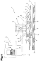
- FIG. 1 is a schematic representation of a gripping device 1 for receiving workpieces 2 of a stack 3 of the workpieces 2, in particular for sheet-metal workpieces 2 shown.
- the gripping device 1 is as shown on an arm 4 of a handling device 5, not shown in detail, for example, robot attached.
- a gripper head 6 is equipped according to the embodiment shown with gripping means 7, for example with a vacuum generator 8, standing in line connection suction cups 9, which of course magnets, pliers etc. can be used.
- the gripping device 1 For lifting the workpiece 2 from the stack 3, the gripping device 1 is positioned with respect to the stack 3, in a predetermined gripping position by means of a control and monitoring device 10 of the handling device 5 and with the suction cups 9 or other gripping means 7 on a surface 11 of the workpiece. 2 set up, which are taken in the case of the application of suction cups 9 by attaching a vacuum from the vacuum generator 8 and lifted from the stack 3 to be a manufacturing process to be performed, eg bending, punching, welding, etc., a manufacturing plant by means of the handling device 5 to be supplied.
- the gripping device 1 on the gripper head. 6 a detection device 12, consisting of a pulse generator 13 and a vibration sensor 15 arranged at a distance 14 thereto.
- the pulse generator 13 is formed in the embodiment shown by an actuated by means of an electromagnet 16 impact plunger 17 which is controlled by the control and / or control device 10 to excite a shock pulse in the workpiece 2 a vibration.
- the vibration sensor 15 for vibration detection provided vibration sensor 15 is, for example, an acceleration sensor 18 which is placed by means of a pressing device 19 with a predetermined force on the surface 11 of the detected by the gripping device 1 workpiece.
- the acceleration sensor 18 is line-connected to a storage and / or analysis module 20 via a bus system 21.
- the storage and / or analysis module 20 is in the illustrated embodiment, an external computer, which is preferably integrated in the control and monitoring device 10. It should be noted that, of course, the data transmission can also be wireless.
- a control of the pulse generator 3, which carries with its impact ram 17 with minimum contact time on the surface 11 of the workpiece 2 is a shock and thus the workpiece 2 oscillates.
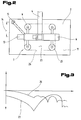
- the oscillation spectrum is recorded and processed in the storage and / or analysis module 20 by means of Fourier transformation and compared with a stored for the workpiece 2 in the storage and / or analysis module 20 oscillation spectrum.
- This reference curve of the waveform is determined in a detection process on a part of the work or determined in a previously performed so-called teach-in process for a number of predetermined parts of the work 2 and the Data of the reference curves stored in the memory and / or analysis module 20.
- a possible arrangement for a example rectangular blank of the workpiece 2 of the gripping means 7 and the pulse generator 13 and the vibration sensor 15 is shown on the gripper head 6 in a simplified representation.
- the pulse generator 13 and the vibration sensor 15 are arranged in the greatest possible distance 14 to each other. Furthermore, these are placed on the workpiece 2 as possible outside of a limited by the gripping means 7, the vibration propagation by a damping effect obstructing surface region 23 of the surface 11 set up.
- an imaginary connecting line 24 between the pulse generator 13 and the vibration sensor 15 should not run through or between contact points 25 of the gripping means 7.
- a pulse pulse applied by the pulse generator 13 to the vibration excitation work piece 2 in order to suppress a damping effect takes place in a contact time of approximately 200 ms.
- the pulse sensor 15 of the, as in Fig. 1 described pressing device 19 be applied to the surface 11 with a uniform, not influenced by the vibrations pad pressure.
- the gripping area, as it is bounded by the gripping means 7, for example, by the contact points 25, is to be positioned within tolerances with respect to the workpiece edges formed, with such a requirement also in view of a positioning accuracy for subsequent processing anyway sought and today usual handling equipment is also achieved.
- the detection device 12 (see Fig. 1 ) with the pulse generator 13, vibration sensor 15 and the memory and / or analysis module 20 (see Fig. 1 )
- An assembly which is on coupling device on the gripper head 6 solvable and thus arranged interchangeable and contacted with the gripper head 6 for supplying further arranged on this components, such as sensors, optical positioning device, etc., bus system for energy and data transmission becomes.
- FIG. 4 Now a further embodiment of the gripping device 1 is shown in a simplified schematic representation.
- the gripping head 6 is mounted on the arm 4 of the handling device 5 not shown further.
- the pulse generator 13 is arranged on the gripper head 6, which communicates with a further transmitting and receiving module 29 of the storage and / or analysis module 20, for example via a transmitting and receiving module 28 in wireless communication connection.
- a further transmitting and receiving module 29 of the storage and / or analysis module 20 for example via a transmitting and receiving module 28 in wireless communication connection.
- the storage and / or analysis module 20 is connected via a line 31 or also wirelessly with the control and monitoring device 10 in connection.
- the pulse generator 13 has the impact plunger 17, which emits a predetermined impact pulse by means of a drive 32 with a predetermined impact energy to the detected by the gripping device 1 workpiece part 2. Furthermore, the vibration exciter 13 is provided with a sensing element 33, e.g. a piezo sensor 34, provided. This sensor element 33 serves to determine the acceleration of the impact ram 17 for impulse application of the workpiece 2 and the determination of the delay after the pulse application.
- a sensing element 33 e.g. a piezo sensor 34
- the determined acceleration and deceleration data are evaluated and compared with stored in a memory module 36 reference data and is to determine after this comparison, whether of the gripping device 1, a single workpiece. 2 or two or more workpieces 2 adhering to each other via an oil film 37 or a cutting burr, etc., have been detected, since a ratio formed from the acceleration and deceleration of the percussion ram 17 forms a clear analysis result.
- FIG. 5 another embodiment of the gripping device 1 according to the invention is shown.
- the suction cups 9 are placed on the surface 11 of the provided on the stack 3 workpiece part 2 and lifted by conditioning the vacuum from the stack 3.
- At least one of the gripping means 7, in the concrete embodiment 2 thereof, are connected via pressure sensors 38 to Determining a caused by the weight of the workpiece 2 force (compressive or tensile force) supported on the gripper head 6.
- measured values recorded by the pressure sensors 38 for the force are conducted via measuring lines 39 to the storage and / or analysis module 20 and compared in this with stored weight data of the workpiece 2 intended for further processing.
- the gripping device 1 is a workpiece 2 or, as shown in dashed lines, by adhesion of e.g. as a result of an oil film 37, two or more of the workpieces 2 have been received.
- the pressure forces measured as a result of the weight of the workpiece 2 - arrow 40 - of at least two gripping means 7 acting on the workpiece 2 have been taken in the correct position with respect to a reference position. This is done via the determined according to the force components position or a distance 41 of the center of gravity 42 of the workpiece 2 with respect to the reference position.
- the storage and / or analysis module 20 is of course, as already described above, via the line 31 to the control and monitoring device 10 and computer 22 line connected and has the memory module 36 on. As already mentioned, wireless communication is also possible.
- a separation of several recorded by adhesion workpieces 2 by the arrangement of a in the surface 11 of the workpiece 2 perpendicular direction according to - double arrow 43 - adjustable gripping means 7 is possible.
- a central gripping means 7 is mounted on the gripper head 6 by means of an adjusting drive 44, for example a pressure cylinder 45 which can be acted upon by a pressure medium.
Landscapes
- Engineering & Computer Science (AREA)
- Mechanical Engineering (AREA)
- Robotics (AREA)
- Manipulator (AREA)
- Bending Of Plates, Rods, And Pipes (AREA)
- Sheets, Magazines, And Separation Thereof (AREA)
Description
Die Erfindung betrifft eine Greifeinrichtung, wie im Oberbegriff des Anspruchs 1 beschrieben sowie ein V erfahren zum Betrieb der Greifeinrichtung wie im Oberbegriff des Anspruchs 8 beschrieben.The invention relates to a gripping device, as described in the preamble of
Eine solche Greifeinrichtung und ein solches Verfahren sind aus dem Dokument
Bei der Werkstückmanipulation mit automatisierten Handhabungseinrichtungen, sogenannter Roboter, bei denen mittels Greifeinrichtung die Werkteile aus einer Bereitstellung ergriffen und zur Bearbeitung an eine Fertigungseinrichtung zuzuführen sind, treten oftmals bei einem Stapel von geschnittenen oder gestanzten flachen Werkteilen, wie Blechen, Störungen bei der Zufuhr dadurch auf, dass die Werkteile, bedingt durch Oberflächenverunreinigungen, z.B. durch einen Ölfilm von Schneid- oder Stanzöl, aneinander haften und anstelle eines Einzelwerkstückes zwei oder mehr der Werkstücke von der Greifeinrichtung, z.B. einem Sauggreifer, Magnetgreifer etc., angehoben werden und damit Störungen im Fertigungsablauf eintreten.In the case of workpiece manipulation with automated handling devices, so-called robots, in which the workpieces are gripped by a gripping device and supplied to a production facility for processing, disturbances in the supply often occur in the case of a stack of cut or stamped flat workpieces such as metal sheets in that the workpieces, due to surface contamination, eg by an oil film of cutting or stamping oil, adhere to each other and instead of a single workpiece two or more of the workpieces from the gripping device, e.g. a suction gripper, magnetic gripper, etc., are raised and thus interfere with the production process.
Aus dem Stand der Technik sind nun Möglichkeiten zur Abhilfe bekannt, wobei eine Möglichkeit darin besteht, die Greifeinrichtung mit einer Gewichtssensorik auszustatten, um anhand des an der Greifeinrichtung ermittelten Gewichts mit im Rechner hinterlegten Parametern auf die ergriffenen Stücke zu schließen und gegebenenfalls eine Werkteiltrennung durchzuführen.Possibilities for remedying the situation are now known from the state of the art, with one possibility being to equip the gripping device with a weight sensor in order to conclude the gripped pieces with parameters determined in the computer by means of the weight determined on the gripping device and, if appropriate, to carry out a workpiece part separation.
Eine weitere Möglichkeit, die der Stand der Technik bietet, besteht darin, nach dem Ergreifen des Werkteils eine optische Vermessung, z.B. eines Dickenmaßes vorzunehmen und aus dem ermittelten Maß nach in einem Rechner hinterlegten Parametern daraus die Anzahl der ergriffenen Werkteile zu ermitteln, um bei Bedarf eine Teiletrennung nachfolgend durchzuführen. Weiters sind auch Ultraschall-, Wirbelstrom- und magnetische Messverfahren bekannt mittels der ebenfalls eine Gesamtdicke ermittelt wird und daraus, wie bereits bei der optischen Vermessung ausgeführt, die weitere Vorgangsweise bestimmt wird.Another possibility, which provides the state of the art, is to make an optical measurement, such as a thickness measurement after gripping the workpiece and determine from the determined amount stored in a computer parameters from the number of parts taken workpieces, if necessary to carry out a partial separation below. Furthermore, ultrasound, eddy current and magnetic measuring methods are also known by means of which a total thickness is likewise determined and from this, as already explained in the optical measurement, the further procedure is determined.
Weiters ist es auch bekannt, vor dem Ergreifen von Werkteilen, bei denen die Möglichkeit eines Aneinanderhaftens besteht, eine Vereinzelungsvorrichtung vorzusehen. Derartige Vorrichtungen erfordern jedoch einen hohen Aufwand an mechanischen Komponenten und ist deren Betrieb mit erhöhten Steuerungs- und Kontrollaufwand verbunden.Furthermore, it is also known to provide a separating device before grasping workpieces where there is a possibility of sticking together. However, such devices require a high cost of mechanical components and their operation is associated with increased control and control effort.
Aufgabe der Erfindung ist es nunmehr eine Greifeinrichtung für eine Handhabungseinrichtung zu schaffen, die ein rasches Erkennen der Anzahl der von der Greifeinrichtung aufgenommenen Werkteilen ermöglicht und bei geringem Gewicht und gedrängter Bauweise der Greifeinrichtung realisierbar ist.The object of the invention is now to provide a gripping device for a handling device, which allows rapid recognition of the number of recorded by the gripping device parts and can be realized with low weight and compact design of the gripping device.
Diese Aufgabe der Erfindung wird durch die im Kennzeichenteil des Anspruches 1 wiedergegebenen Merkmale erreicht. Die Kontrolle, ob es sich bei dem aufgenommenen Werkteil um einen Einzelteil oder um mehrere Teile handelt, und ob es sich um den richtigen Werkteil handelt, wird unmittelbar am Greiferkopf durchgeführt. Durch die Auswertung des Frequenzspektrums der Schwingungen im Werkteil erfolgt ein Vergleich mit hinterlegten Kennlinien umnittelbar am Greiferkopf. Die großen Datenmengen, die für eine Analyse erforderlich sind, belasten damit nicht zusätzlich das für Steuerungsmaßnahmen der Handhabungseinrichtung und des Greiferkopfes bestehende Kommunikationssystem, insbesondere ein Bus-System.This object of the invention is achieved by the reproduced in the characterizing part of
Möglich ist aber auch eine Ausbildung nach Anspruch 2, weil dadurch unmittelbar an der Erregerquelle die für eine Schwingungsanalyse am erfassten Werkteil maßgeblichen Daten aus dem Erregerimpuls ermittelt werden, wodurch störende Einflüsse vermieden werden und für die Analyse eine geringere Schwingungsbandbreite für die Basisdaten herangezogen werden kann und damit die Verfahrenssicherheit größer ist.However, an embodiment according to
Es ist aber auch eine Ausbildung nach Anspruch 3 vorteilhaft wodurch Leitungsverbindungen entfallen.But it is also an embodiment according to claim 3 advantageous which eliminates cable connections.
Weiters ist eine Ausbildung nach Anspruch 4 vorteilhaft, wodurch eine einfache störungssichere Erregerquelle zur Erzeugung von Schwingungen im Werkteil vorliegt.Furthermore, an embodiment according to
Gemäß der im Anspruch 5 gekennzeichneten Ausführung, kann vorteilhaft ein durch die hohe Anwendungshäufigkeit bewährtes Fühlerelement zum Einsatz gelangen.According to the embodiment characterized in
Gemäß der im Anspruch 6 beschriebenen vorteilhaften Lösung, werden die vom Beschleunigungssensor ermittelten Frequenzspektren unabhängig vom Frequenzverlauf vergleichbar.According to the advantageous solution described in
Eine weitere vorteilhafte Ausbildung beschreibt der Anspruch 7, wodurch eine kompakte Bauform erreicht wird und Erregerquelle und Messquelle über einen Kontaktpunkt wirken und damit die Greifergeometrie auf das Analyseergebnis ohne Einfluss bleibt.A further advantageous embodiment of
Die Aufgabe der Erfindung wird auch durch die im Kennzeichenteil des Verfahrensanspruchs 8 wiedergegebenen Merkmale erreicht.The object of the invention is also achieved by the reproduced in the characterizing part of
Zum besseren Verständnis der Erfindung wird diese anhand der in den Fig. dargestellten Ausführungsbeispielen näher erläutert.For a better understanding of the invention, this will be explained in more detail with reference to the embodiments shown in FIGS.
Es zeigen:
- Fig. 1
- eine erfindungsgemäße Greifeinrichtung in schematischer Darstellung;
- Fig. 2
- eine mögliche Anordnung auf einem Greifkopf;
- Fig. 3
- Schwingungs-Impulsdiagramm;
- Fig. 4
- eine weitere Ausbildung der erfindungsgemäßen Greifeinrichtung;
- Fig. 5
- eine andere Ausführung der erfindungsgemäßen Greifeinrichtung.
- Fig. 1
- a gripping device according to the invention in a schematic representation;
- Fig. 2
- a possible arrangement on a gripping head;
- Fig. 3
- Vibration pulse diagram;
- Fig. 4
- a further embodiment of the gripping device according to the invention;
- Fig. 5
- another embodiment of the gripping device according to the invention.
Einführend sei festgehalten, dass in den unterschiedlich beschriebenen Ausführungsformen gleiche Teile mit gleichen Bezugszeichen bzw. gleichen Bauteilbezeichnungen versehen werden, wobei die in der gesamten Beschreibung enthaltenen Offenbarungen sinngemäß auf gleiche Teile mit gleichen Bezugszeichen bzw. gleichen Bauteilbezeichnungen übertragen werden können. Auch sind die in der Beschreibung gewählten Lageangaben, wie z.B. oben, unten, seitlich usw. auf die unmittelbar beschriebene sowie dargestellte Figur bezogen und sind bei einer Lageänderung sinngemäß auf die neue Lage zu übertragen. Weiters können auch Einzelmerkmale oder Merkmalskombinationen aus den gezeigten und beschriebenen unterschiedlichen Ausführungsbeispielen für sich eigenständige erfinderische oder erfindungsgemäße Lösungen darstellen.By way of introduction, it should be noted that in the differently described embodiments, the same parts are provided with the same reference numerals or the same component names, wherein the disclosures contained in the entire description can be mutatis mutandis to the same parts with the same reference numerals or component names. Also, the location information chosen in the description, such as top, bottom, side, etc. related to the immediately described and illustrated figure and are to be transferred to the new situation mutatis mutandis when a change in position. Furthermore, individual features or combinations of features from the different exemplary embodiments shown and described may also represent separate inventive or inventive solutions.
In der
Dabei tritt vielfach das Problem auf, dass durch einen Ölfilm auf der Oberfläche 11 auf den im Stapel 3 gelagerten Werkteilen 2 diese aneinander haften und zwei oder mehr Werkteile 2 gemeinsam abgehoben werden, wie dies in der
Zur Lösung des Problems weist die erfindungsgemäße Greifeinrichtung 1 am Greiferkopf 6 eine Detektiereinrichtung 12, bestehend aus einem Impulsgeber 13 und einen in einem Abstand 14 dazu angeordneten Schwingungsfühler 15 auf. Der Impulsgeber 13 wird im gezeigten Ausführungsbeispiel durch einen mittels einem Elektromagnet 16 betätigten Schlagstößel 17 gebildet, der von der Steuer- und/oder Kontrolleinrichtung 10 angesteuert wird, um durch einen Schlagimpuls im Werkteil 2 eine Schwingung zu erregen. Der Schwingungsfühler 15 zur Schwingungsdetektion vorgesehene Schwingungsfühler 15 ist beispielsweise ein Beschleunigungssensor 18, der mittels einer Andrückvorrichtung 19 mit einer vorgegebenen Kraft auf die Oberfläche 11 des von der Greifeinrichtung 1 erfassten Werkteils aufgesetzt wird. Der Beschleunigungssensor 18 ist mit einem Speicher- und/oder Analysemodul 20 über ein Bus-System 21 leitungsverbunden. Das Speicher- und/oder Analysemodul 20 ist im gezeigten Ausführungsbeispiel ein externer Rechner, der bevorzugt in der Steuer- und Kontrolleinrichtung 10 integriert ist. Es sei erwähnt, dass selbstverständlich die Datenübertragung auch drahtlos erfolgen kann.To solve the problem, the
Erfindungsgemäß ist das Speicher- und Analysemodul 20 unmittelbar am Greiferkopf 6 angeordnet, um damit die vom Beschleunigungssensor 18 ermittelten Daten unmittelbar vor Ort auszuwerten, sodass das Bus-System 21 entlastet wird und die über das Bus-System 21 an die Steuer- und Kontrolleinrichtung 10 übermittelten Daten zur Beurteilung, ob eine Einzel- oder Mehrfachaufnahme von Werkteilen 2 erfolgt ist, auf Informationsimpulse Ja/Nein beschränkt werden.According to the invention, the storage and
Der Vorgang zum Erkennen, ob eine Einzel- oder Mehrfachaufnahme von Werkteilen 2 erfolgt ist, ist nun nachfolgend beschrieben.The process for detecting whether a single or multiple recording of
Nach dem Abheben des Werkteils 2 vom Stapel 3 erfolgt eine Ansteuerung des Impulsgebers 3, der mit seinem Schlagstößel 17 bei minimalster Kontaktzeit auf die Oberfläche 11 des Werkteiles 2 einen Schlag ausführt und damit den Werkteil 2 in Schwingungen versetzt. Mittels des Beschleunigungssensors 18 wird das Schwingungsspektrum aufgenommen und im Speicher- und/oder Analysemodul 20 mittels Fourier-Transformation aufbereitet und mit einem für den Werkteil 2 im Speicher- und/oder Analysemodul 20 hinterlegten Schwingungsspektrum verglichen. Diese Referenzkurve des Schwingungsverlaufes wird in einem Erfassungsprozess an einem Werkteil ermittelt oder in einem im Vorfeld durchgeführtem sogenannter teach-in Verfahren für einen Anzahl vorgegebener Werkteile 2 ermittelt und die Daten der Referenzkurven im Speicher- und/oder Analysemodul 20 hinterlegt. Es braucht nicht besonders ausgeführt werden, dass das Schwingungsverhalten des Werkteils 2 von Material, Dimensionen und Greifpositionen der Greifmittel sowie ganz wesentlich natürlich davon beeinflusst wird, ob ein einzelner Werkteil 2 oder mehrere aneinander haftende Werkteile 2 mit der Greifeinrichtung 1 erfasst wurden.After lifting the
Selbstverständlich ist es möglich, im Speicher- und/oder Analysemodul 20 in Abhängigkeit von der Speicherkapazität für unterschiedliche Werkteile in einer Werkteilmatrix die aufbereiteten Daten des entsprechenden Schwingungsspektrums abzuspeichern und vor Beginn der Verarbeitung des jeweiligen Werkteils 2 über einen Code aufzurufen und für die Analyse auf diese Daten zuzugreifen. Dies ermöglicht eine rasche Umrüstung einer Fertigungsanlage und erhöht damit deren Kapazität und die Wirtschaftlichkeit einer derartigen Anlage.Of course, it is possible to store in memory and / or
In der
Weiters ist von Entscheidung, dass ein vom Impulsgeber 13 auf den Werkteil 2 zur Schwingungserregung aufgebrachter Impulsstoß, um eine Dämpfungswirkung zu unterbinden, in einer Kontaktzeit von etwa 200 ms abläuft. Des weiteren sollte der Impulsfühler 15 von der, wie in der
Erfindungsgemäß bilden die Detektiereinrichtung 12 (siehe
In dem nun in
In der
Der Impulsgeber 13 weist den Schlagstößel 17 auf, der mittels eines Antriebes 32 mit einer vorgegebenen Schlagenergie auf den von der Greifeinrichtung 1 erfassten Werkteil 2 einen vorgegebenen Schlagimpuls abgibt. Weiters ist der Schwingungserreger 13 mit einem Fühlerelement 33, z.B. einem Piezosensor 34, versehen. Dieses Fühlerelement 33 dient der Ermittlung der Beschleunigung des Schlagstößels 17 zur Impulsbeaufschlagung des Werkteils 2 und der Ermittlung der Verzögerung nach der Impulsaufbringung.The
In einem Rechnermodul 35 des Speicher- und/oder Analysemoduls 20, insbesondere einem µController, werden die ermittelten Beschleunigungs- und Verzögerungsdaten ausgewertet und mit in einem Speichermodul 36 hinterlegten Referenzdaten verglichen und ist nach diesem Vergleich festzustellen, ob von der Greifeinrichtung 1 ein einzelnes Werkstück 2 oder zwei oder mehrere über einen Ölfilm 37 oder durch einen Schneidgrat etc. aneinander haftender Werkteile 2 erfasst wurden, da eine aus der Beschleunigung und der Verzögerung des Schlagstößels 17 gebildete Verhältniszahl ein eindeutiges Analyseergebnis bildet.In a
Um die Analyseergebnisse noch weiter zu verfeinern ist es zudem möglich, zusätzlich zu dem mit dem Fühlerelement 33 ausgestattete Impulserreger 13, wie in strichlierten Linien gezeigt, den Greiferkopf 6 mit dem bereits vorhergehenden beschriebenen Schwingungsfühler 15 auszustatten. Dabei wird zur Bewertung ob ein einzelner Werkteil 2 oder mehrere aufgenommen wurden, sowohl das Analysenergebnis aus der Impulsanalyse sowie aus der Schwingungsanalyse herangezogen und damit eine hohe Analysesicherheit erzielt.In order to further refine the analysis results, it is also possible, in addition to the
In der
Beim Anheben des Werkteils 2 vom Stapel 3 werden von den Drucksensoren 38 aufgenommene Messwerte für die Kraft über Messleitungen 39 an das Speicher- und/oder Analysemodul 20 geleitet und in diesem mit hinterlegten Gewichtsdaten des zu einer weiteren Verarbeitung vorgesehenen Werkteils 2 verglichen. Damit ist feststellbar, ob von der Greifeinrichtung 1 ein Werkteil 2 oder, wie in strichlierten Linien gezeigt, durch Anhaftung z.B. infolge eines Ölfilms 37 zwei oder mehrere der Werkteile 2 aufgenommen wurden.When lifting the
Weiters ist durch Vergleich der von den Drucksensoren 38 gelieferten Messdaten der in Folge des Gewichts des Werkteils 2 gemessenen Druckkräfte gemäß - Pfeil 40 - von zumindest zwei am Werkteil 2 anwirkenden Greifmitteln 7 ob der Werkteil 2 in Bezug auf eine Referenzlage lagerichtig ergriffen wurde. Dies erfolgt über die entsprechend den Kraftkomponenten ermittelte Lage bzw. eines Abstandes 41 des Schwerpunktes 42 des Werkteils 2 in Bezug auf die Referenzlage.Furthermore, by comparison of the measured data supplied by the
Das Speicher- und/oder Analysemodul 20 ist selbstverständlich, wie bereits vorhergehend beschrieben, über die Leitung 31 mit der Steuer- und Kontrolleinrichtung 10 und Rechner 22 leitungsverbunden und weist das Speichermodul 36 auf. Wie aber auch bereits erwähnt ist eine drahtlose Kommunikation ebenso möglich.The storage and / or
Wie nun weiters der
Der Ordnung halber sei abschließend darauf hingewiesen, dass zum besseren Verständnis des Aufbaus der Greifeinrichtung diese bzw. deren Bestandteile teilweise unmaßstäblich und/oder vergrößert und/oder verkleinert dargestellt wurden.For the sake of order, it should finally be pointed out that, for a better understanding of the structure of the gripping device, these or their components have been shown partly unevenly and / or enlarged and / or reduced in size.
Es sei noch erwähnt, dass die einzelnen in den
Claims (8)
- A gripping device (1) for a handling device (5), in particular for a robot, for picking up and feeding a work part (2) from a stack (3) of work parts (2) provided to a production facility such as a sheet metal bending machine, punch press, welding equipment etc., the gripping device having a gripping head (6) equipped with gripping means (7) such as suction cups (9), magnets, pincers etc., and with a detection device (12) for the work part (2) picked up by the gripping means (7), the detection device (12) comprising at least one pulse generator (13) as vibration exciter acting upon the work part (2) and with at least one vibration sensor (15), and with a storage and/or analysis module (20) for a vibration analysis, characterised in that the detection device (12) forms a constructional unit with the storage and/or analysis module (20) and is detachably arranged on the gripper head (6) and is contacted via a bus system (21), in particular an ASi bus, with a controlling and/or a monitoring device (10) of the production facility.
- The gripping device according to claim 1, characterised in that the pulse generator (13) is equipped with a sensor element (33), in particular a piezo sensor (34).
- The gripping device according to claim 1 or 2, characterised in that data transmission between the vibration sensor (15) and the storage and/or analysis module (20) and/or the controlling and/or monitoring device (10) is performed wirelessly.
- The gripping device according to one of the preceding claims, characterised in that the pulse generator (13) is formed by an impact ram (17) acted upon by motion energy.
- The gripping device according to one of the preceding claims, characterised in that the vibration sensor (15) is formed by an acceleration sensor (18) placeable upon a surface (11) of the work part (2).
- The gripping device according to claim 5, characterised in that the acceleration sensor (18) is mounted on the gripper head (6) via a pressing-on device (19).
- The gripping device according to one of the preceding claims, characterised in that the pulse generator (13) is equipped with the vibration sensor (15).
- A method for operating a gripping device (1) according to one of claims 1 to 7, for feeding work parts (2) to a production facility, in particular a sheet metal bending machine for reshaping, having a handling device (5), whereby the work parts (2) are picked up from a stack (3) by means of a gripping device (1) of the handling device equipped with gripping means (7), whereupon the work part (2) is set to vibrate by a pulse generator (13) acted upon by a controlling and/or monitoring device (10) arranged on the gripping device (1), and the vibration spectrum is recorded as pulse signals by a vibration sensor (15) arranged on the gripping device (1) and directed to a storage and/or analysis module (20) and compared therein to stored reference data of the vibration spectrum of the work part (2), characterised in that the vibration sensor (15) is placed against a surface (11) of the work part (2) by a pressing-on device (19), whereupon a pulse burst with a contact time of approx. 200 ms is applied to the work part (2) by the pulse generator (13) in order to generate vibrations.
Applications Claiming Priority (3)
| Application Number | Priority Date | Filing Date | Title |
|---|---|---|---|
| AT14562002 | 2002-09-26 | ||
| AT14562002 | 2002-09-26 | ||
| PCT/AT2003/000282 WO2004028939A2 (en) | 2002-09-26 | 2003-09-25 | Gripping device comprising means for detecting double feeding and method for the operation thereof |
Publications (2)
| Publication Number | Publication Date |
|---|---|
| EP1542918A2 EP1542918A2 (en) | 2005-06-22 |
| EP1542918B1 true EP1542918B1 (en) | 2016-11-16 |
Family
ID=32034599
Family Applications (1)
| Application Number | Title | Priority Date | Filing Date |
|---|---|---|---|
| EP03797971.3A Expired - Lifetime EP1542918B1 (en) | 2002-09-26 | 2003-09-25 | Gripping device comprising means for detecting double feeding and method for the operation thereof |
Country Status (4)
| Country | Link |
|---|---|
| US (1) | US7792609B2 (en) |
| EP (1) | EP1542918B1 (en) |
| AU (1) | AU2003265707A1 (en) |
| WO (1) | WO2004028939A2 (en) |
Families Citing this family (32)
| Publication number | Priority date | Publication date | Assignee | Title |
|---|---|---|---|---|
| AT503196B1 (en) * | 2006-01-19 | 2008-06-15 | Trumpf Maschinen Austria Gmbh | BENDING PEG WITH FEEDING DEVICE AND METHOD FOR THE OPERATION THEREOF |
| DE102006025387B3 (en) * | 2006-05-31 | 2007-10-25 | Pepperl + Fuchs Gmbh | Monitoring supply of sheet metal from stack to forming operation, includes arrangement of sensors to register sheet numbers and avoid inadvertent maloperation of handling equipment |
| CH710725B1 (en) * | 2008-04-17 | 2016-08-15 | Soudronic Ag | Hubtischabstapler and Behälterzargenschweissvorrichtung with such. |
| JP4565023B2 (en) * | 2008-07-04 | 2010-10-20 | ファナック株式会社 | Article take-out device |
| EP2331301B1 (en) * | 2008-08-29 | 2018-10-17 | ABB Research Ltd. | Robotic picking of parts from a bin using force feedback |
| EP2470333A2 (en) | 2009-08-27 | 2012-07-04 | ABB Research Ltd. | Robotic picking of parts from a parts holding bin |
| JP5085749B2 (en) * | 2011-02-21 | 2012-11-28 | ファナック株式会社 | Rod-shaped member conveying device |
| JP5717503B2 (en) * | 2011-03-30 | 2015-05-13 | 富士重工業株式会社 | Press product inspection equipment |
| US8826787B2 (en) * | 2012-08-22 | 2014-09-09 | Xerox Corporation | Cutting machine media feeder system with fixed in-feed and out-feed trays |
| SE537072C2 (en) * | 2013-06-05 | 2014-12-30 | Mizelda Ab | Folding device and use of folding device for folding a blank |
| CN103708713A (en) * | 2013-12-26 | 2014-04-09 | 深圳市华星光电技术有限公司 | Clamping mechanism, liquid crystal panel cutting machine and liquid crystal panel cutting process |
| KR101641164B1 (en) * | 2014-11-25 | 2016-07-20 | 유도스타자동화 주식회사 | Milti-joint robot having a weighting apparatus |
| JP6549714B2 (en) * | 2014-12-17 | 2019-07-24 | ノルグレン オートメーション ソーリューションズ エルエルシーNorgren Automation Solutions,Llc. | Device for detecting a workpiece, workpiece evaluation system, manufacturing system, processing method of workpiece |
| CN104972008B (en) * | 2015-06-10 | 2017-03-15 | 南京邮电大学 | A kind of sheet material positioning grasping system for being applied to automatic production line and positioning grasping means |
| JP6616170B2 (en) * | 2015-12-07 | 2019-12-04 | ファナック株式会社 | Machine learning device, laminated core manufacturing apparatus, laminated core manufacturing system, and machine learning method for learning stacking operation of core sheet |
| US9446612B1 (en) | 2015-12-11 | 2016-09-20 | Xerox Corporation | Multiple-gripper architecture for multi-sheet-length digital printing |
| EP3311950A1 (en) * | 2016-10-19 | 2018-04-25 | Bystronic Laser AG | Transport device, method and computer program product for loading and unloading at least one material machining machine |
| EP3311963A1 (en) * | 2016-10-21 | 2018-04-25 | Bystronic Laser AG | Positionable robot cell, production device with a processing unit and with positionable robot cell and method for operating such a robot cell which can be positioned |
| TWI636246B (en) * | 2017-03-21 | 2018-09-21 | 中國鋼鐵股份有限公司 | Measurement system for compatibility of self-bonding electrical steel and punching oil and measurement method thereof |
| WO2019052656A1 (en) | 2017-09-15 | 2019-03-21 | Swiss Transportation Research Institute Ag | Door system for a vacuum train |
| JP7078321B2 (en) * | 2018-03-23 | 2022-05-31 | 株式会社Screenホールディングス | Insertion paper removing device and interleaving paper removal method |
| CA3090600A1 (en) | 2018-04-23 | 2019-10-31 | Dynamic Concept | Robot and automated guided vehicle combination for aluminum furnace operations |
| JP7033753B2 (en) * | 2018-06-28 | 2022-03-11 | パナソニックIpマネジメント株式会社 | Pillar supply method, glass panel unit manufacturing method, and pillar supply device |
| TWI796524B (en) * | 2018-10-19 | 2023-03-21 | 日商Thk股份有限公司 | actuator system |
| US11224975B2 (en) | 2018-10-23 | 2022-01-18 | Ford Global Technologies, Llc | Impulse electrically generated force separation of blanks for the automated destacking of metal sheet |
| CN110034343B (en) * | 2019-05-21 | 2024-07-30 | 博众精工科技股份有限公司 | Press mounting device and press mounting system |
| DE102020116626A1 (en) * | 2020-06-24 | 2021-12-30 | Trumpf Werkzeugmaschinen Gmbh + Co. Kg | Method for removing a workpiece part in a processing machine, data processing program, safety device and processing machine |
| CN112693884A (en) * | 2020-12-14 | 2021-04-23 | 湖南赛智科技有限公司 | Electromagnetic vibration sucker and vacuum adsorption material taking method for battery cell pole piece |
| CN112960386B (en) * | 2021-02-02 | 2023-12-08 | 苏州华亚智能科技股份有限公司 | Board separating mechanism with adhesion recognition function and working method thereof |
| KR20240009220A (en) * | 2022-07-13 | 2024-01-22 | 주식회사 엘지에너지솔루션 | Adsorption device |
| EP4360771A1 (en) * | 2022-10-28 | 2024-05-01 | Talleres Roiri, S.L. | Machine and method for de-stacking metal sheets |
| EP4509273A1 (en) * | 2023-08-18 | 2025-02-19 | AM-Flow Holding B.V. | Object sorting device and method of sorting objects and a disentanglement station |
Family Cites Families (17)
| Publication number | Priority date | Publication date | Assignee | Title |
|---|---|---|---|---|
| JP2770960B2 (en) * | 1988-10-06 | 1998-07-02 | キヤノン株式会社 | SOR-X-ray exposure equipment |
| US5089970A (en) * | 1989-10-05 | 1992-02-18 | Combustion Engineering, Inc. | Integrated manufacturing system |
| US5150288A (en) * | 1989-12-18 | 1992-09-22 | Honda Giken Kogyo Kabushiki Kaisha | Production management system and method of transmitting data |
| DE69125986T2 (en) * | 1990-02-23 | 1997-08-21 | Amada Co., Ltd., Isehara, Kanagawa | METHOD AND DEVICE FOR MEASURING THE ANGLE OF A WORKPIECE |
| DE4222990B4 (en) | 1991-07-12 | 2004-04-08 | Roman Koller | Method and device for evaluating a touch |
| JPH0753095A (en) * | 1993-08-12 | 1995-02-28 | Murata Mach Ltd | Two plate detecting device for plate material |
| JPH07328965A (en) * | 1994-06-03 | 1995-12-19 | Toyota Motor Corp | Damping control method, natural vibration period measuring method, and damping control device |
| US5969973A (en) * | 1994-11-09 | 1999-10-19 | Amada Company, Ltd. | Intelligent system for generating and executing a sheet metal bending plan |
| JP3727657B2 (en) * | 1994-11-09 | 2005-12-14 | 株式会社 アマダ | Finger pad force detection system |
| US5822207A (en) * | 1996-05-06 | 1998-10-13 | Amadasoft America, Inc. | Apparatus and method for integrating intelligent manufacturing system with expert sheet metal planning and bending system |
| US5828575A (en) * | 1996-05-06 | 1998-10-27 | Amadasoft America, Inc. | Apparatus and method for managing and distributing design and manufacturing information throughout a sheet metal production facility |
| US5854994A (en) * | 1996-08-23 | 1998-12-29 | Csi Technology, Inc. | Vibration monitor and transmission system |
| US5799530A (en) * | 1996-12-20 | 1998-09-01 | Amada Company, Limited | Method of bending operations and bending system using the same |
| JP3289633B2 (en) * | 1997-02-26 | 2002-06-10 | 松下電器産業株式会社 | Lead frame transfer method |
| US6102193A (en) * | 1998-06-30 | 2000-08-15 | Rivers, Jr.; Ernest M. | Method and apparatus for providing parts to workpieces |
| DE10023241C2 (en) * | 2000-05-12 | 2003-08-07 | Hermann Hagel | Transfer device and method for controlling a transfer device |
| WO2003004961A2 (en) * | 2001-07-05 | 2003-01-16 | Schenck Rotec Corporation | Self-calibrating machines for balancing work pieces and methods of machine calibration |
-
2003
- 2003-09-25 EP EP03797971.3A patent/EP1542918B1/en not_active Expired - Lifetime
- 2003-09-25 AU AU2003265707A patent/AU2003265707A1/en not_active Abandoned
- 2003-09-25 US US10/529,262 patent/US7792609B2/en not_active Expired - Fee Related
- 2003-09-25 WO PCT/AT2003/000282 patent/WO2004028939A2/en not_active Ceased
Also Published As
| Publication number | Publication date |
|---|---|
| US20060184282A1 (en) | 2006-08-17 |
| AU2003265707A1 (en) | 2004-04-19 |
| AU2003265707A8 (en) | 2004-04-19 |
| WO2004028939A2 (en) | 2004-04-08 |
| WO2004028939A3 (en) | 2004-05-27 |
| EP1542918A2 (en) | 2005-06-22 |
| US7792609B2 (en) | 2010-09-07 |
Similar Documents
| Publication | Publication Date | Title |
|---|---|---|
| EP1542918B1 (en) | Gripping device comprising means for detecting double feeding and method for the operation thereof | |
| EP1973824B1 (en) | Bending press having a loading device and method for operating it | |
| EP2134483B1 (en) | Method for establishing a setup parameter value for a bending press | |
| EP2222419B1 (en) | Device and method for quality testing sheet metal parts | |
| DE10248298A1 (en) | Rivet placing tool with monitoring of parameters of pulling device acting on rivet bolt gripping device for monitoring riveting process | |
| DE102016114378A1 (en) | Handling device and method for monitoring a handling device | |
| EP1469958A1 (en) | Placing tool with means for controlling placing processes | |
| DE102017130873B4 (en) | Device and method for monitoring a wedge drive tool | |
| DE3921653C2 (en) | ||
| EP2508276B1 (en) | Sheet metal removal station | |
| DE102014007554A1 (en) | Method and device for monitoring a joining process | |
| DE102011118419A1 (en) | Diagnosing deterioration state of electrodes of welding gun for connecting components, comprises detecting mechanical vibration of welding gun and analyzing mechanical vibration measuring signal to detect wear condition of electrodes | |
| DE102016224174A1 (en) | Method and device for monitoring a punch riveting device | |
| DE102006032829B3 (en) | Device for arranging or deforming shaft workpieces, comprises a lifting device, which is propelled by impact plunger on work piece, two supports that are supported between the workpiece, and measuring device coupled with a force sensor | |
| EP2928682B1 (en) | Stamping device with a sensor and method for transmitting a sensor signal | |
| DE102011080042A1 (en) | Positioning device and method for positioning | |
| WO2003059550A1 (en) | Setting tool comprising a device for measuring tensile stress | |
| DE10224402A1 (en) | Welding tongs for electrical resistance welding has two electrodes, of which at least one is attached to electrode arm, force sensor arranged on one electrode arm holder | |
| DE102016207697A1 (en) | Method for connecting at least two components by means of a punch riveting device, punch riveting device and manufacturing device | |
| DE102016214534A1 (en) | Punch riveting device and manufacturing device | |
| EP4284587B1 (en) | Method for operating an ultrasonic connecting device | |
| DE20210840U1 (en) | Setting tool, especially a riveting tool has a piezoelectric sensor for measuring the tensile force applied to the rivet shaft so that the force can be accurately measured without a power supply to the sensor | |
| DE4137750C2 (en) | Device for quality monitoring of joining processes for the production of press connections | |
| DE3420839A1 (en) | Automatic feed apparatus for presses for sheet-metal working | |
| EP1992429A1 (en) | Setting tool with means for monitoring setting procedures |
Legal Events
| Date | Code | Title | Description |
|---|---|---|---|
| PUAI | Public reference made under article 153(3) epc to a published international application that has entered the european phase |
Free format text: ORIGINAL CODE: 0009012 |
|
| 17P | Request for examination filed |
Effective date: 20050326 |
|
| AK | Designated contracting states |
Kind code of ref document: A2 Designated state(s): AT BE BG CH CY CZ DE DK EE ES FI FR GB GR HU IE IT LI LU MC NL PT RO SE SI SK TR |
|
| AX | Request for extension of the european patent |
Extension state: AL LT LV MK |
|
| DAX | Request for extension of the european patent (deleted) | ||
| RIN1 | Information on inventor provided before grant (corrected) |
Inventor name: SPERRER, GERHARD Inventor name: STRASSER, HAGEN |
|
| GRAP | Despatch of communication of intention to grant a patent |
Free format text: ORIGINAL CODE: EPIDOSNIGR1 |
|
| INTG | Intention to grant announced |
Effective date: 20160615 |
|
| GRAS | Grant fee paid |
Free format text: ORIGINAL CODE: EPIDOSNIGR3 |
|
| GRAA | (expected) grant |
Free format text: ORIGINAL CODE: 0009210 |
|
| AK | Designated contracting states |
Kind code of ref document: B1 Designated state(s): AT BE BG CH CY CZ DE DK EE ES FI FR GB GR HU IE IT LI LU MC NL PT RO SE SI SK TR |
|
| REG | Reference to a national code |
Ref country code: GB Ref legal event code: FG4D Free format text: NOT ENGLISH |
|
| RIN1 | Information on inventor provided before grant (corrected) |
Inventor name: STRASSER, HAGEN Inventor name: SPERRER, GERHARD |
|
| REG | Reference to a national code |
Ref country code: CH Ref legal event code: EP |
|
| REG | Reference to a national code |
Ref country code: IE Ref legal event code: FG4D Free format text: LANGUAGE OF EP DOCUMENT: GERMAN |
|
| REG | Reference to a national code |
Ref country code: AT Ref legal event code: REF Ref document number: 845695 Country of ref document: AT Kind code of ref document: T Effective date: 20161215 |
|
| REG | Reference to a national code |
Ref country code: DE Ref legal event code: R096 Ref document number: 50315580 Country of ref document: DE |
|
| REG | Reference to a national code |
Ref country code: SE Ref legal event code: TRGR |
|
| REG | Reference to a national code |
Ref country code: NL Ref legal event code: MP Effective date: 20161116 |
|
| PG25 | Lapsed in a contracting state [announced via postgrant information from national office to epo] |
Ref country code: NL Free format text: LAPSE BECAUSE OF FAILURE TO SUBMIT A TRANSLATION OF THE DESCRIPTION OR TO PAY THE FEE WITHIN THE PRESCRIBED TIME-LIMIT Effective date: 20161116 Ref country code: GR Free format text: LAPSE BECAUSE OF FAILURE TO SUBMIT A TRANSLATION OF THE DESCRIPTION OR TO PAY THE FEE WITHIN THE PRESCRIBED TIME-LIMIT Effective date: 20170217 |
|
| PG25 | Lapsed in a contracting state [announced via postgrant information from national office to epo] |
Ref country code: FI Free format text: LAPSE BECAUSE OF FAILURE TO SUBMIT A TRANSLATION OF THE DESCRIPTION OR TO PAY THE FEE WITHIN THE PRESCRIBED TIME-LIMIT Effective date: 20161116 Ref country code: ES Free format text: LAPSE BECAUSE OF FAILURE TO SUBMIT A TRANSLATION OF THE DESCRIPTION OR TO PAY THE FEE WITHIN THE PRESCRIBED TIME-LIMIT Effective date: 20161116 Ref country code: PT Free format text: LAPSE BECAUSE OF FAILURE TO SUBMIT A TRANSLATION OF THE DESCRIPTION OR TO PAY THE FEE WITHIN THE PRESCRIBED TIME-LIMIT Effective date: 20170316 |
|
| PG25 | Lapsed in a contracting state [announced via postgrant information from national office to epo] |
Ref country code: DK Free format text: LAPSE BECAUSE OF FAILURE TO SUBMIT A TRANSLATION OF THE DESCRIPTION OR TO PAY THE FEE WITHIN THE PRESCRIBED TIME-LIMIT Effective date: 20161116 Ref country code: EE Free format text: LAPSE BECAUSE OF FAILURE TO SUBMIT A TRANSLATION OF THE DESCRIPTION OR TO PAY THE FEE WITHIN THE PRESCRIBED TIME-LIMIT Effective date: 20161116 Ref country code: SK Free format text: LAPSE BECAUSE OF FAILURE TO SUBMIT A TRANSLATION OF THE DESCRIPTION OR TO PAY THE FEE WITHIN THE PRESCRIBED TIME-LIMIT Effective date: 20161116 Ref country code: RO Free format text: LAPSE BECAUSE OF FAILURE TO SUBMIT A TRANSLATION OF THE DESCRIPTION OR TO PAY THE FEE WITHIN THE PRESCRIBED TIME-LIMIT Effective date: 20161116 Ref country code: CZ Free format text: LAPSE BECAUSE OF FAILURE TO SUBMIT A TRANSLATION OF THE DESCRIPTION OR TO PAY THE FEE WITHIN THE PRESCRIBED TIME-LIMIT Effective date: 20161116 |
|
| REG | Reference to a national code |
Ref country code: DE Ref legal event code: R097 Ref document number: 50315580 Country of ref document: DE |
|
| PG25 | Lapsed in a contracting state [announced via postgrant information from national office to epo] |
Ref country code: BG Free format text: LAPSE BECAUSE OF FAILURE TO SUBMIT A TRANSLATION OF THE DESCRIPTION OR TO PAY THE FEE WITHIN THE PRESCRIBED TIME-LIMIT Effective date: 20170216 Ref country code: IT Free format text: LAPSE BECAUSE OF FAILURE TO SUBMIT A TRANSLATION OF THE DESCRIPTION OR TO PAY THE FEE WITHIN THE PRESCRIBED TIME-LIMIT Effective date: 20161116 |
|
| REG | Reference to a national code |
Ref country code: FR Ref legal event code: PLFP Year of fee payment: 15 |
|
| PLBE | No opposition filed within time limit |
Free format text: ORIGINAL CODE: 0009261 |
|
| STAA | Information on the status of an ep patent application or granted ep patent |
Free format text: STATUS: NO OPPOSITION FILED WITHIN TIME LIMIT |
|
| 26N | No opposition filed |
Effective date: 20170817 |
|
| PGFP | Annual fee paid to national office [announced via postgrant information from national office to epo] |
Ref country code: DE Payment date: 20170912 Year of fee payment: 15 Ref country code: FR Payment date: 20170915 Year of fee payment: 15 |
|
| PG25 | Lapsed in a contracting state [announced via postgrant information from national office to epo] |
Ref country code: SI Free format text: LAPSE BECAUSE OF FAILURE TO SUBMIT A TRANSLATION OF THE DESCRIPTION OR TO PAY THE FEE WITHIN THE PRESCRIBED TIME-LIMIT Effective date: 20161116 |
|
| PGFP | Annual fee paid to national office [announced via postgrant information from national office to epo] |
Ref country code: SE Payment date: 20170908 Year of fee payment: 15 |
|
| REG | Reference to a national code |
Ref country code: CH Ref legal event code: PL |
|
| GBPC | Gb: european patent ceased through non-payment of renewal fee |
Effective date: 20170925 |
|
| PG25 | Lapsed in a contracting state [announced via postgrant information from national office to epo] |
Ref country code: MC Free format text: LAPSE BECAUSE OF FAILURE TO SUBMIT A TRANSLATION OF THE DESCRIPTION OR TO PAY THE FEE WITHIN THE PRESCRIBED TIME-LIMIT Effective date: 20161116 |
|
| REG | Reference to a national code |
Ref country code: IE Ref legal event code: MM4A |
|
| REG | Reference to a national code |
Ref country code: BE Ref legal event code: MM Effective date: 20170930 |
|
| PG25 | Lapsed in a contracting state [announced via postgrant information from national office to epo] |
Ref country code: LU Free format text: LAPSE BECAUSE OF NON-PAYMENT OF DUE FEES Effective date: 20170925 |
|
| REG | Reference to a national code |
Ref country code: DE Ref legal event code: R082 Ref document number: 50315580 Country of ref document: DE Representative=s name: ABP BURGER RECHTSANWALTSGESELLSCHAFT MBH, DE |
|
| PG25 | Lapsed in a contracting state [announced via postgrant information from national office to epo] |
Ref country code: CH Free format text: LAPSE BECAUSE OF NON-PAYMENT OF DUE FEES Effective date: 20170930 Ref country code: GB Free format text: LAPSE BECAUSE OF NON-PAYMENT OF DUE FEES Effective date: 20170925 Ref country code: IE Free format text: LAPSE BECAUSE OF NON-PAYMENT OF DUE FEES Effective date: 20170925 Ref country code: LI Free format text: LAPSE BECAUSE OF NON-PAYMENT OF DUE FEES Effective date: 20170930 |
|
| PG25 | Lapsed in a contracting state [announced via postgrant information from national office to epo] |
Ref country code: BE Free format text: LAPSE BECAUSE OF NON-PAYMENT OF DUE FEES Effective date: 20170930 |
|
| REG | Reference to a national code |
Ref country code: AT Ref legal event code: MM01 Ref document number: 845695 Country of ref document: AT Kind code of ref document: T Effective date: 20170925 |
|
| PG25 | Lapsed in a contracting state [announced via postgrant information from national office to epo] |
Ref country code: AT Free format text: LAPSE BECAUSE OF NON-PAYMENT OF DUE FEES Effective date: 20170925 |
|
| REG | Reference to a national code |
Ref country code: DE Ref legal event code: R119 Ref document number: 50315580 Country of ref document: DE |
|
| REG | Reference to a national code |
Ref country code: SE Ref legal event code: EUG |
|
| PG25 | Lapsed in a contracting state [announced via postgrant information from national office to epo] |
Ref country code: SE Free format text: LAPSE BECAUSE OF NON-PAYMENT OF DUE FEES Effective date: 20180926 |
|
| PG25 | Lapsed in a contracting state [announced via postgrant information from national office to epo] |
Ref country code: HU Free format text: LAPSE BECAUSE OF FAILURE TO SUBMIT A TRANSLATION OF THE DESCRIPTION OR TO PAY THE FEE WITHIN THE PRESCRIBED TIME-LIMIT; INVALID AB INITIO Effective date: 20030925 |
|
| PG25 | Lapsed in a contracting state [announced via postgrant information from national office to epo] |
Ref country code: DE Free format text: LAPSE BECAUSE OF NON-PAYMENT OF DUE FEES Effective date: 20190402 |
|
| PG25 | Lapsed in a contracting state [announced via postgrant information from national office to epo] |
Ref country code: FR Free format text: LAPSE BECAUSE OF NON-PAYMENT OF DUE FEES Effective date: 20180930 |
|
| PG25 | Lapsed in a contracting state [announced via postgrant information from national office to epo] |
Ref country code: CY Free format text: LAPSE BECAUSE OF NON-PAYMENT OF DUE FEES Effective date: 20161116 |
|
| PG25 | Lapsed in a contracting state [announced via postgrant information from national office to epo] |
Ref country code: TR Free format text: LAPSE BECAUSE OF FAILURE TO SUBMIT A TRANSLATION OF THE DESCRIPTION OR TO PAY THE FEE WITHIN THE PRESCRIBED TIME-LIMIT Effective date: 20161116 |