EP1542339A1 - Motor, method of manufacturing motor, and driving control device for motor - Google Patents
Motor, method of manufacturing motor, and driving control device for motor Download PDFInfo
- Publication number
- EP1542339A1 EP1542339A1 EP03741421A EP03741421A EP1542339A1 EP 1542339 A1 EP1542339 A1 EP 1542339A1 EP 03741421 A EP03741421 A EP 03741421A EP 03741421 A EP03741421 A EP 03741421A EP 1542339 A1 EP1542339 A1 EP 1542339A1
- Authority
- EP
- European Patent Office
- Prior art keywords
- exciting
- phase
- motor
- current
- teeth
- Prior art date
- Legal status (The legal status is an assumption and is not a legal conclusion. Google has not performed a legal analysis and makes no representation as to the accuracy of the status listed.)
- Withdrawn
Links
Images






Classifications
-
- B—PERFORMING OPERATIONS; TRANSPORTING
- B62—LAND VEHICLES FOR TRAVELLING OTHERWISE THAN ON RAILS
- B62D—MOTOR VEHICLES; TRAILERS
- B62D5/00—Power-assisted or power-driven steering
- B62D5/04—Power-assisted or power-driven steering electrical, e.g. using an electric servo-motor connected to, or forming part of, the steering gear
- B62D5/0403—Power-assisted or power-driven steering electrical, e.g. using an electric servo-motor connected to, or forming part of, the steering gear characterised by constructional features, e.g. common housing for motor and gear box
-
- H—ELECTRICITY
- H02—GENERATION; CONVERSION OR DISTRIBUTION OF ELECTRIC POWER
- H02K—DYNAMO-ELECTRIC MACHINES
- H02K3/00—Details of windings
- H02K3/46—Fastening of windings on the stator or rotor structure
- H02K3/52—Fastening salient pole windings or connections thereto
- H02K3/521—Fastening salient pole windings or connections thereto applicable to stators only
- H02K3/522—Fastening salient pole windings or connections thereto applicable to stators only for generally annular cores with salient poles
-
- H—ELECTRICITY
- H02—GENERATION; CONVERSION OR DISTRIBUTION OF ELECTRIC POWER
- H02P—CONTROL OR REGULATION OF ELECTRIC MOTORS, ELECTRIC GENERATORS OR DYNAMO-ELECTRIC CONVERTERS; CONTROLLING TRANSFORMERS, REACTORS OR CHOKE COILS
- H02P6/00—Arrangements for controlling synchronous motors or other dynamo-electric motors using electronic commutation dependent on the rotor position; Electronic commutators therefor
- H02P6/10—Arrangements for controlling torque ripple, e.g. providing reduced torque ripple
-
- H—ELECTRICITY
- H02—GENERATION; CONVERSION OR DISTRIBUTION OF ELECTRIC POWER
- H02K—DYNAMO-ELECTRIC MACHINES
- H02K2203/00—Specific aspects not provided for in the other groups of this subclass relating to the windings
- H02K2203/09—Machines characterised by wiring elements other than wires, e.g. bus rings, for connecting the winding terminations
-
- H—ELECTRICITY
- H02—GENERATION; CONVERSION OR DISTRIBUTION OF ELECTRIC POWER
- H02P—CONTROL OR REGULATION OF ELECTRIC MOTORS, ELECTRIC GENERATORS OR DYNAMO-ELECTRIC CONVERTERS; CONTROLLING TRANSFORMERS, REACTORS OR CHOKE COILS
- H02P2209/00—Indexing scheme relating to controlling arrangements characterised by the waveform of the supplied voltage or current
- H02P2209/07—Trapezoidal waveform
Definitions
- the present invention relates to a motor, a method for manufacturing the motor, and a motor drive controller. More particularly, the invention relates to a motor including a motor-wiring bus bar used for electrically connecting a lead wire wound around a stator core and its manufacturing method, relates to a permanent-magnet motor which requires low cogging torque, low torque ripple, and high output with compact size and which includes a rectangular-wave driven distributed-coil stator, relates to a brushless DC motor used in an electrically driven power steering system having no motor lock and in which size reduction, low torque ripple, and low cost are achieved, and relates to a brushless-motor drive controller in which the toque ripple is reduced with high rpm in a low-torque load range.
- Bus bars have been used to connect lead wires (hereinafter, referred to as coils) wound around motor stator cores in view of assemble efficiency.
- coils lead wires
- JP-A-2001-103700 and JP-A-2001-86695 describe that bus bars are used because of their high connection efficiency and that the bus bars are manufactured by stamping copper plates.
- Fig. 1 shows the mechanical structure of a brushless DC motor.
- Fig. 2 shows the electrical circuit thereof.
- a stator 1000 includes stator cores 51-U, 51-V, 51-W, 52-U, 52-V, and 52-W corresponding to U-phase, V-phase, and W-phase, respectively, and coils 101-U, 101-V, 101-W, 102-U, 102-V, and 102-W wound around the respective cores.
- the connection of the coils will then be described.
- one ends of the coils 101-U and 102-U are connected to a ring-shaped U-phase bus bar 1-U and the other ends are connected to a ring-shaped N-phase bus bar 1-N.
- one ends of the coils 101-V and 102-V are connected to a ring-shaped V-phase bus bar 1-V and the other ends are connected to a ring-shaped N-phase bus bar 1-N.
- the coils of W-phase are also connected similarly.
- the connection between the coils and the bus bars in Fig. 1 shows electrical connection, in which specific connecting means are not generally electrical wires but engagement of bus bars with coils. Accordingly, since the connection with the ring-shaped bus bars is easier than that with electrical wires, it is useful in increasing assembly efficiency.
- a three-phase current is generated by an inverter including a power source DC and switches SU, SV, SW, SX, SY, and SZ, which is fed through power lines YU, YV, and YW to the coils 101-U, 102-U, 101-V, 102-V, 101-W, and 102-W of the stator 1000.
- the coils are in Y-connection, one ends of the coils are connected with the U-, V-, W-phase bus bars 1-U, 1-V, and 1-W in correspondence with the respective phases and all of the other ends of the coils are connected with the neutral-point bus bar 1-N.
- a three-phase current is fed to the coils of the motor by the inverter including the DC power source and the switches.
- the current is fed to the power lines YU, YV, and YW, the bus bars, and the coils, which will be specifically described with the U-phase as an example.
- the U-phase current flows through the power line YU into a terminal 33-U of the U-phase bus bar 1-U, passes through a U-phase ring conductor 2-U and is fed from a terminal 31-U to the coil 101-U or from a terminal 32-U to the coil 102-U.
- the current flowing through the coils 101-U and 102-U flows into the bus bar 1-N and then flows from the terminals of the bus bar 1-N into the V-phase coils 101-V and 102-V and the W-phase coils 101-W and 102-W.
- the currents in the coils 101-V and 102-V join together through terminals 31-V and 32-V of the bus bar 1-V at the bus bar 1-V and returns from a terminal 33-V through the power line YV to the DC power source.
- the W-phase coil current passes through the bus bar 1-W and returns to the DC power source.
- the three-phase current flowing through the U-, V-, and W-phase coils generates a rotary magnetic field to rotate a rotor (not shown), thereby driving the motor.
- the bus bars are very important members to combine the currents.
- the conventional motors using the ring-shaped bus bar have a structural problem in achieving size reduction. Specifically, referring to Fig. 3, since the stack of ring-shaped bus bars 1-U, 1-V, 1-W, and 1-N is used, it is four times as thick as that of the bus bar (four bus bars of U-, V-, W-, and N-phase), having a problem in reducing the size of the motor.
- the method for manufacturing the motor including the ring-shaped bus bars has the following problem:
- the ring conductors have been made by stamping, thus having the problem that the remaining of the stamped member is wasted.
- the present invention has been made in view of the above problems. Accordingly, it is a first object of the invention to provide a motor including a motor-wiring bus bar suitable for size reduction and a method for manufacturing a motor including an economical motor-wiring bus bar which makes good use of the member.
- a permanent-magnet motor which is disclosed in, for example, JP-A-10-126982.
- the permanent-magnet motor achieves the reduction of the cogging torque by arranging the teeth such that the centers of the slot openings of the stator deviate from the positions at equal intervals.
- the permanent-magnet motor includes annular permanent magnets constituting M magnetic poles (M is an even number) to construct a rotor and T teeth facing the permanent magnets arranged at irregular intervals, a winding groove (slot) between the teeth being wound with a coil, and the teeth being joined to a yoke to construct a stator.
- the teeth are arranged such that the centers of the slot openings of the stator deviate from the position of regular intervals T by a deviation of ⁇ N ⁇ 180/ ⁇ C(T/2 + 1) ⁇ , where C is the least common multiple of the number M of the permanent magnets and the number T of the teeth and N is an integer from 1 to T/2.
- the present invention has been made in view of the above problems. Accordingly, it is a second object of the invention to provide a permanent-magnet motor capable of achieving low cogging torque, low torque ripple, and high output with compact size, being driven with a rectangular-wave current, and including a distributed-coil stator.
- a shaft 102 of a steering wheel 101 is joined to tie rods 106 of wheels through a reduction gear 103, universal joints 104a and 104b, and a pinion rack mechanism 105.
- the shaft 102 includes a torque sensor 107 for sensing the steering torque of the steering wheel 101.
- a motor 108 for applying an auxiliary power to the steering wheel 101 is joined to the shaft 102 through the reduction gear 103. It is important here that the motor 108 used for an important safety component such as the electrically driven power steering system is required to have significantly high reliability.
- the motor 108 actually has disadvantages, one of which is that, with a brushless DC motor, foreign matter is caught between the rotor and the stator to lock the motor.
- Fig. 5(A) shows the longitudinal section of the brushless DC motor and Fig. 5(B) shows the cross section thereof.
- the brushless DC motor includes a rotor 9 having a permanent magnet 9-1 mounted to the outer periphery and a stator 10 wound with coils.
- the stator 10 includes a stator core 12 having a plurality of teeth 11 and coils 14 wound around slots 13 between the stator core 12 and the teeth 11. Since the brushless DC motor generally uses sintered permanent magnets for the rotor, the permanent magnets are covered with a nonmagnetic metal plate or the like to prevent locking even when the permanent magnets become chipped by external impact.
- the stator has openings between the adjacent teeth 11 to wind the coils 14 around the stator core 12. If foreign matter 50 such as insulator chips or varnish for hardening the coil enters the space between the rotor 9 and the teeth 11 through the openings, there is a possibility that the rotor is locked.
- An example of the method for preventing the motor lock is adopting a divided core in which the inner peripheries of the adjacent teeth are joined together. The joining of the teeth, however, increases leakage of flux to decrease the torque constant of the brushless DC motor, thus reducing output. Also, it rapidly increases the ripple of the counter electromotive voltage to increase torque ripple, thus decreasing the operability of the electrically driven power steering system.
- Another lock prevention method is molding the stator and the coil and filling the adjacent openings with resin, which has a disadvantage of increasing the cost.
- the invention has been made in view of the above problems. Accordingly, it is a third object of the invention to provide a brushless DC motor in which the motor output does not decrease, the torque ripple is low, the cost is low, and the motor is not locked.
- the brushless motors used as the primary drive of automotive power steering systems generally include three or more exciting phases, which are driven with a rectangular-wave exciting current.
- the motor driving circuit rotates the rotor by exciting five-phase (hereinafter, referred to as an a-phase to e-phase) exciting coils a to e disposed to surround the outer periphery of the rotor of the motor at an interval of 72 electrical degrees with a rectangular-wave current, while switching the coils sequentially phase by phase, by four-phase simultaneous exciting under the control of a control circuit of a microcomputer, etc.
- an a-phase to e-phase five-phase exciting coils a to e disposed to surround the outer periphery of the rotor of the motor at an interval of 72 electrical degrees with a rectangular-wave current, while switching the coils sequentially phase by phase, by four-phase simultaneous exciting under the control of a control circuit of a microcomputer, etc.
- the motor current flows through four phases of the five phases; the circuit is constructed such that the resistances of the exciting coils are equal to feed the current through the phases in good balance.
- the motor driving circuits are generally constructed of ten field effect transistors (FETs).
- FETs field effect transistors
- the ten transistors connect to the coil circuit of the motor such that two corresponding transistors are connected in series to construct five series transistor circuits, each of which is connected between the positive and negative terminals of the power source, and in which the connections of the two transistors of each series transistor circuit are connected to the external ends of the five star (Y)-connected exciting coils a to e.
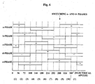
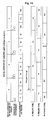
- Fig. 6 The direction and length of the exciting current (rectangular wave) fed from the motor driving circuit to the exciting coils relative to the rotation angle (electrical angle) of the rotor is shown in Fig. 6 by way of example. Specifically, the rotor is continuously rotated by sequentially switching the exciting coils phase by phase every 36 electrical degrees and exciting each phase coil during 144 electrical degrees. Referring to Fig.
- the a-phase current flows in the plus direction in sections (1) and (2), at zero in section (3), in the minus direction in sections (4) to (7), at zero in section (8), passes through sections (9) to (10), and again flows in the plus direction in section (1).
- the b-phase current flows in the plus direction in sections (1) to (4), at zero in section (5), in the minus direction in sections (6) to (9), at zero in section (10), and again flows in the plus direction in section (1).
- the c-phase current flows in the minus direction in section (1), at zero in section (2), in the plus direction in sections (3) to (6), at zero in section (7), passes through sections (8) to (10), and again flows in the minus direction in section (1).
- the d-phase current flows in the minus direction in sections (1) to (3), at zero in section (4), in the plus direction in sections (5) to (8), at zero in section (9) and again flows in the minus direction in section (10).
- the e-phase current flows at zero in section (1), in the minus direction in sections (2) to (5), at zero in section (6), in the plus direction in sections (7) to (10), and again becomes zero in section (1).
- two of the five exciting coils are switched in the opposite direction at the boundaries (at the switching at every 36 electrical degrees) of the sections (1) to (10).
- a brushless DC motor (BLDCM) and a permanent-magnet synchronous motor (PMSM) are known as the brushless motor.
- Examples of the former are disclosed in JP-A-11-356083 and JP-A-2002-269569 which adopt commutation control.
- An example of the latter is disclosed in JP-A-2000-201461.
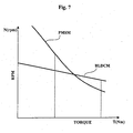
- the brushless DC motor is lower in rpm in a low-torque load range than the permanent-magnet synchronous motor.
- this disadvantageously increases the torque ripple with an increased rpm to cause a noise due to the torque ripple.
- the weakening field control facilitates the increase in rpm in the low-torque load range; however, decreases the rpm in a rated load range, being inferior to the brushless DC motor in terms of size reduction and high output of the motor in the rated load range.
- the electrically driven power steering system requires a compact, high-output, low-torque-ripple, low-noise motor and controller and also high rpm during low torque loading (for example, in emergency).
- the invention has been made in view of the above problems. Accordingly, it is a fourth object of the invention to provide a brushless-motor drive controller for a brushless DC motor in which high rpm is achieved and torque ripple is reduced during low torque loading.
- the present invention relates to a motor including a motor-wiring bus bar, comprising: a plurality of annular ring conductors connecting lead wires of said motor or connecting said lead wires and a power line together; and a plurality of terminals attached to said ring conductors.
- the first object of the invention is achieved by setting said ring conductors different in diameter and arranging said ring conductors concentrically in a same plane, wherein: said motor includes a stator in which a plurality of stator cores wound with said lead wires is arranged in a circle.
- said ring conductor from part of a annulus ring, or covering said ring conductors with insulating coating, or making that a current to said lead wires of said motor has multiple phases and color of said lead wire is the same as color of said ring conductor which is equal in phase with said lead wire.
- the invention relates to a method for manufacturing a motor including a motor-wiring bus bar, characterized in that said motor comprising: a plurality of annular ring conductors connecting lead wires of said motor or connecting said lead wires and a power line together; and a plurality of terminals attached to said ring conductors.
- the first object of the invention is achieved by making that said motor includes a stator in which a plurality of stator cores wound with said lead wires is arranged in a circle; and said ring conductor is formed by transforming a rectangular plate into annular shape or slicing a cylinder.
- the present invention relates to a permanent-magnet motor capable of achieving low cogging torque, low torque ripple, and high output with compact size and including a distributed-coil stator driven with a rectangular-wave current.
- the second object of the invention is advantageously achieved by making that in one of said cycle of angle width of teeth, when p is an even number, kind of angle width of teeth is set to three and, when p is an odd number, said kind of angle width of teeth is set to four; and for combination, angle widths of odd teeth are set to be equal and angle widths of even teeth are set to be different, or making that in one of said cycle of angle widths of teeth, when p is an even number, kind of angle width of teeth is set to three and, when p is an odd number, said kind of angle width of teeth is set to four; and for combination, angle widths of even teeth are set to be equal and angle widths of odd teeth are set to be different, or adopting every other pole winding (one coil for one slot) as method of winding so that voltages induced in coils are equal in phase, or making that when ⁇ is equally spaced angle width and ⁇ is available said angle width of teeth, range of ⁇ is expressed as a ⁇ ⁇ ⁇ ⁇ ⁇ b
- the present invention relates to a brushless DC motor.
- the third object of the invention is achieved by a brushless DC motor, comprising: a rotatable rotor in which permanent magnet is fixed around outer periphery; and a stator core formed by a plurality of teeth holding coil around cylindrical inner periphery, wherein: S ⁇ G holds, where S is slot opening width between teeth and G is space length between said rotor and said stator core.
- the present invention relates to a brushless-motor drive controller in which high rpm is achieved and torque ripple is reduced in a low torque load range.
- the fourth object of the invention is achieved by a brushless-motor drive controller having a plurality of exciting phases, comprising: a exciting-phase-current-instruction-signal generating means for generating exciting-phase-current instruction signal for each exciting phase; and a exciting-current control means for controlling exciting current for each exciting phase by current feedback control in accordance with said exciting-phase-current instruction signal generated by said exciting-phase-current-instruction-signal generating means, wherein: said exciting-phase-current-instruction-signal generating means advances electrical angle of said exciting-phase-current instruction signal having shape other than a rectangular wave by a predetermined angle, so that comparing to driving speed range during drive control of rectangular-wave exciting current, driving speed range of said brushless-motor is expanded.
- a brushless-motor drive controller having a plurality of exciting phases, comprising: a exciting-phase-current-instruction-signal generating means for generating exciting-phase-current instruction signal for each exciting phase; and a exciting-current control means for controlling exciting current for each exciting phase by current feedback control in accordance with said exciting-phase-current instruction signal generated by said exciting-phase-current-instruction-signal generating means, wherein: said exciting-phase-current-instruction-signal generating means advances electrical angle of said exciting-phase-current instruction signal in which rates of change in exciting current of two commutation phases agree with each other during commutation by a predetermined angle to achieve weakening field.
- a brushless-motor drive controller having a plurality of exciting phases, comprising: a exciting-phase-current-instruction-signal generating means for generating exciting-phase-current instruction signal for each exciting phase; and a exciting-current control means for controlling exciting current for each exciting phase by current feedback control in accordance with said exciting-phase-current instruction signal generated by said exciting-phase-current-instruction-signal generating means, wherein: said exciting-phase-current-instruction-signal generating means advances electrical angle of said exciting-phase-current instruction signal which is a trapezoidal-wave or a sine-wave by a predetermined angle to achieve weakening field.
- a brushless-motor drive controller having a plurality of exciting phases, comprising: a exciting-phase-current-instruction-signal generating means for generating exciting-phase-current instruction signal for each exciting phase; and a exciting-current control means for controlling exciting current for each exciting phase by current feedback control in accordance with said exciting-phase-current instruction signal generated by said exciting-phase-current-instruction-signal generating means, wherein: said exciting-phase-current-instruction-signal generating means generates said exciting-phase-current instruction signal including phase-angle advancing from a induced electromotive force, a output torque, and a rotation speed of said brushless motor.
- the fourth object of the invention is advantageously achieved by a brushless-motor drive controller, wherein a rotation angle of rotor of said brushless motor is given by an angle estimation signal estimated from a rotor-position signal detected by a rotor-position detector, motor current, etc. or a brushless-motor drive controller, characterized in that when rotation speed of said motor exceeds a predetermined value, said controller shifts to weakening field control by phase-angle advancing.
- the ring conductors 2-U, 2-V, 2-W, and 2-N are manufactured with different diameters, for example, with the ring diameter decreased in order of, e.g., U-phase, V-phase, W-phase, and N-phase, to which projecting terminals 31-U, 31-V, 31-W, 31-N and so on are mounted to the peripheries thereof; thus, the phase bus bars 1-U, 1-V, 1-W, and 1-N are completed.
- the bus bars 1-U, 1-V, 1-W, and 1-N are then concentrically assembled in one plane of the ring conductors.
- the extracting ends of the coils are extracted in correspondence with the terminal positions of the bus bars, which are connected together as shown in Figs. 1 and 2 of the description of the background art.
- the electrical connection is exactly the same as that of the background art, so that the motor can maintain the same performance as that of the background art.
- bus bars of this embodiment eliminates the necessity of stacking the bus bars, thus remarkably reducing the height.
- the height is only a quarter of that of the conventional stacked bus bars as shown in Fig. 3, remarkably reducing the height to achieve a compact motor.
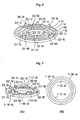
- Fig. 9(A) shows an assembly of bus bars according to the second embodiment in perspective view.
- Fig. 9(B) shows the assembled bus bars in plan view.
- the bus bars do not necessarily require to have a perfect ring (annular) shape as electrically connecting member, even a part of ring shape functions as electrically connecting member.
- the bus bar is hereinafter referred to as a ring-piece bus bar.
- ring-piece bus bars 1-U-A, 1-V-A, 1-W-A, and 1-N-A are manufactured with different diameters and concentrically assembled in one plane, as in the first embodiment.
- the coil extracting positions of the coils are limited because the ring conductors are smaller than those of the embodiment of Fig. 8.
- the ring-piece bus bars are therefore suitable for motors having small number of coils.
- the height of the assembled ring-piece bus bars can be smaller than that of the conventional stacked one, offering an advantage in reducing the size of motors and a great economical effect of decreasing the number of components.
- the bus bar is not generally single but multiple, which are generally arranged in close vicinity, so that they may come in contact with one another. The contact would cause electrical shortage to damage the motor function. It is thus considered that an insulation space is provided or an insulator is placed therebetween, which will decrease working efficiency. Accordingly, applying an insulator to the ring conductors in advance will prevent electrical shortage even if the bas bars come in contact with one another, improving assembly efficiency and eliminating useless space to reduce the size of the motor.
- An increase in the number of the stator cores increases the number of phase coils connected to the ring conductors.
- the increase in the number of the connected wires raises the possibility of miswiring.
- the color of the coil of individual phase and the ring conductor of the same phase as that of the coil are colored in the same color.
- the bus bars 1-U, 1-V, 1-W, and 1-N of the U-phase, V-phase, W-phase, and N-phase are colored in red, blue, white, and green, respectively, the coils with the same phase can be connected together at a glance.
- the lead wire of the red coil 101-U adjacent to the power source connects to the red bus bar 1-U, that of the blue coil 101-V connects to the blue bus bar 1-V, and that of the white coil 101-W connects to the white bus bar 1-W.
- the lead wires of the coils of all the phases adjacent to the neutral point connect to the green bus bar 1-N.
- the method will be described for manufacturing the motor including the motor-wiring bus bars according to the invention.
- Fig. 10(A) shows a copper rectangular plate 500 serving as the material of the ring conductors, which is transformed into annular shape to form a ring conductor 2.
- the ring conductor 2 includes projecting terminals 31, 32, and 33 for electrically connecting to the coils 100-U and 101-U and the power line YU around the periphery to form a bus bar 1 constructed of a ring conductor and terminals, shown in Fig. 10(B).
- the ring conductor 2 can also be manufactured without using the rectangular plate.
- a copper cylinder 600 is sliced into the ring conductor 2, to which the projecting terminals 31, 32, and 33 are attached for connecting coils to the ring conductor, the bus bar 1 is completed. Also in this case, the member is not wasted, different from stamping manufacture.
- the thickness of the rectangular plate and the sliced cylinder is determined depending on the capacity of the current flowing through the ring conductor 2.
- the angle widths of the teeth mean an angle between the centers of adjacent slot openings. Specifically, they are T1 to T12 in Figs. 12, 13, 15 and 16 and T1 to T18 in Figs. 17 and 14.
- Fig. 15 shows a conventional permanent-magnet motor including four-pole 12-slot distributed coils in sectional view.
- a ring-shaped permanent magnet 201 includes four magnetic poles at regular intervals of 90 degrees to construct a rotor 200. Twelve teeth 203 facing the permanent magnet 201 are arranged at regular intervals, winding grooves (slots) between the adjacent teeth 203 are wound with coils and the teeth 203 are held by a yoke 204 to construct a stator 202.
- the rotor 200 rotates around a shaft (not shown) by a rotating magnetic field generated from the current flowing through the coils of the stator 202.
- Fig. 16 shows the development of the magnetic poles and the teeth 203 of the conventional permanent-magnet motor of Fig. 15. As shown in Fig. 16, the four magnetic poles of the permanent-magnet motor are developed in order of N, S, N, and S. The 12 teeth 203 are also developed, in which the angles widths T1 to T12 for the 12 teeth 203 are equal.
- the positions where the pitch of the magnetic poles (the switching between the N-pole and the S-pole) and the pitch of the teeth 203 (the angle widths of the teeth) agree with each other are four positions, A, B, C, and D, surrounded by a rectangular frame.
- the pitch of the magnetic poles is expressed in mechanical angle
- four positions, 0 degree, 90 degrees, 180 degrees, and 270 degrees are given.
- the pitch of the teeth 203 is expressed as 12 positions of 0 degree, 30 degrees, 60 degrees, 90 degrees, 120 degrees, 150 degrees, 180 degrees, 210 degrees, 240 degrees, 270 degrees, 300 degrees, and 330 degrees.
- all the four positions in the pitch of the magnetic poles agree with the pitch of the teeth 203 in angle.
- the conventional permanent-magnet motor of Fig. 15 adopts adjacent-pole wiring in which two coils are wound for one slot, it includes four coils for each phase.
- the U-phase winding is constructed of four coils, U1, U2, U3, and U4
- the V-phase winding is constructed of four coils, V1, V2, V3, and V4
- the W-phase winding is constructed of four coils, W1, W2, W3, and W4.
- Fig. 15 clearly shows that two coils are wound for one slot.
- Cogging torque generates by the change in magnetic energy.
- the conventional permanent-magnet motor shown in Figs. 15 and 16 has as many as four positions where the pitch of the magnetic poles and the pitch of the teeth agree to each other, posing the problem of increasing the cogging torque.
- Fig. 12 shows a sectional view of the permanent-magnet motor including four-pole 12-slot distributed coils (a first embodiment), according to the invention.
- a ring-shaped permanent magnet 201 includes four magnetic poles at regular intervals of 90 degrees to construct a rotor 200. Twelve teeth 203 facing the permanent magnet 201 are held in a yoke 204 to construct a stator 202, winding grooves (slots) between the adjacent teeth 203 are wound with coils.
- the rotor 200 rotates around a shaft (not shown) by a rotating magnetic field generated from the current flowing through the coils of the stator 202.
- Fig. 13 shows the development of the magnetic poles and the teeth 203 of the permanent-magnet motor of Fig. 12.
- the permanent-magnet motor of the invention includes four magnetic poles, which are developed in order of N, S, N, and S.
- the 12 teeth 203 are also developed.
- the angle widths of the 12 teeth 203 have a cycle.
- this embodiment has a total of three cycles: the angle widths of the teeth, T1, T2, T3, and T4, construct one cycle, the angle widths of the teeth, T5, T6, T7, and T8, construct another cycle, and the angle widths of the teeth, T9, T10, T11, and T12, construct still another cycle.
- the permanent-magnet motor including four-pole 12-slot distributed coils (the first embodiment) according to the invention, since the cycle of the angle widths of the teeth is 120 degrees, the phase deviates from the pitch of the magnetic poles, 90 degrees. This allows the cogging frequency higher to thereby reducing the cogging torque.
- the kind of the angle widths of the teeth is set to three when p is an even number, while it is set to four when p is an odd number in the cycle of the angle width of one tooth (the kind of the angle widths of the teeth is three in this embodiment).
- the angle widths of the odd teeth are set to be equal and the angle widths of the even teeth are set to be different.
- T9 T11 and T10 ⁇ T12 hold in the cycle of teeth angle widths, T9, T10, T11, and T12.
- the permanent-magnet motor including four-pole 12-slot distributed coils according to the invention adopts every-other-pole wiring in which one coil is wound for one slot, it includes two coils for each phase.
- the U-phase winding is constructed of two coils, U1 and U2
- the V-phase winding is constructed of two coils, V1 and V2
- the W-phase winding is constructed of two coils, W1 and W2.
- Fig. 12 clearly shows that one coil is wound for one slot.
- the permanent-magnet motor including distributed coils according to the invention adopts the combination of the angle widths of the teeth and the every-other-pole distributed winding (one coil for one slot), the phases of the voltage induced in the coils do not deviate, thus not increasing torque ripple.
- the range of the available angle width ⁇ of the tooth is expressed in terms of the angle width ⁇ at equal intervals as the expression (5) a ⁇ ⁇ ⁇ ⁇ ⁇ b ⁇ ⁇ where a and b are coefficients determined depending on the torque constant or the reduction ratio of the cogging-torque.
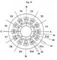
- Fig. 17 shows the development of the magnetic poles and the teeth of a conventional permanent-magnet motor including six-pole 18-slot distributed coils.
- the six magnetic poles of the conventional permanent-magnet motor are developed in order of N, S, N, S, N, and S.
- Eighteen teeth are also developed, in which all the angle widths T1 to T18 for the 18 teeth are equal.
- the positions where the pitch of the magnetic poles (the switching between the N-pole and the S-pole) and the pitch of the teeth (the angle widths of the teeth) agree with each other are six positions, A, B, C, D, E, and F, surrounded by a rectangular frame.
- the pitch of the magnetic poles is expressed in mechanical angle
- six positions of 0 degree, 60 degrees, 120 degrees, 180 degrees, 240 degrees, and 300 degrees are given.
- the pitch of the teeth is expressed as 18 positions of 0 degree, 20 degrees, 40 degrees, 60 degrees, 80 degrees, 100 degrees, 120 degrees, 140 degrees, 160 degrees, 180 degrees, 200 degrees, 220 degrees, 240 degrees, 260 degrees, 280 degrees, 300 degrees, 320 degrees, and 340 degrees.
- the conventional permanent-magnet motor including six-pole 18-slot distributed coils, all the six positions of the pitch of the magnetic poles and the pitch of the teeth agree with each other in angle.
- the conventional permanent-magnet motor including six-pole 18-slot distributed coils adopts adjacent-pole wiring in which two coils are wound for one slot, it includes six coils for each phase.
- the U-phase winding is constructed of six coils, U1, U2, U3, U4, U5, and U6
- the V-phase winding is constructed of six coils, V1, V2, V3, V4, V5, and V6
- the W-phase winding is constructed of six coils, W1, W2, W3, W4, W5, and W6.
- the phase difference between the coils U1 and U2 is 60 degM (mechanical angle), i.e. 180 degE (electrical angle)
- reversing the winding direction brings that the voltages induced in the coils become equal in phase.
- Fig. 14 shows the development of the magnetic poles and the teeth of the permanent-magnet motor including six-pole 18-slot distributed coils according to the invention.
- the number S of slots is 18 and the number 2p of poles is 6, p becomes 3.
- the six magnetic poles of the permanent-magnet motor are developed in order of N, S, N, S, N, and S.
- the 18 teeth are also developed.
- the cycle of the angle widths of the 18 teeth is expressed as equations (6) and (7).
- 360/18 x 6 120 holds, so that the cycle of the angle widths of the teeth is 120 degrees.
- this embodiment has a total of three cycles: the angle widths of the teeth, T1, T2, T3, T4, T5, and T6 construct one cycle, the angle widths of the teeth, T7, T8, T9, T10, T11, and T12 construct another cycle, and the angle widths of the teeth, T13, T14, T15, T16, T17, and T18 construct still another cycle.
- the permanent-magnet motor including six-pole 18-slot distributed coils according to the invention, since the cycle of the angle width of the teeth is 120 degrees, the phase deviates from the pitch of the magnetic poles, 60 degrees. This allows the cogging frequency higher, thereby reducing cogging torque.
- the kind of the angle width of the teeth is set to three, while when p is an odd number, it is set to four (the kind of the angle widths of the teeth is four in this embodiment); for the combination, the angle widths of odd teeth are set to be equal and the angle widths of even teeth are set to be different.
- the positions where the pitch of the magnetic poles (the switching between the N-pole and the S-pole) and the pitch of the teeth (the angle widths of the teeth) agree with each other are three positions, A, B, and C, surrounded by a rectangular frame.
- the permanent-magnet motor including six-pole 18-slot distributed coils adopts every-other-pole wiring in which one coil is wound for one slot, it includes three coils for each phase.
- the U-phase winding is constructed of three coils, U1, U2, and U3
- the V-phase winding is constructed of three coils, V1, V2, and V3
- the W-phase winding is constructed of three coils, W1, W2, and W3.
- the angle widths of even teeth may be set to be equal and the angle widths of odd teeth may be set to be different.
- Fig. 18 shows the brushless DC motor of the invention in cross section, which includes the same components as those of the known art of Fig. 5(B).
- An important point in Fig. 18 is not the components but their dimensional relationship. Specifically, the opening width S of the slot 13 i.e. the opening width S between the teeth 11, is smaller than the space length G between the rotor 9 and the stator core 10. Briefly, it is that the relationship S ⁇ G holds.
- the foreign matter 50 such as varnish for hardening the coils 14 does not enter from the slots 13 through the openings between the teeth 11 (the opening width S) into the space between the rotor 9 (the permanent magnet 9-1 in the strict sense) and the teeth 11 to lock the rotation of the rotor 9.
- the size of the foreign matter 50 passing through the openings between the teeth 11 (the opening width S) is, of course, smaller than the opening width S, whereas the space length G between the rotor 9 and the teeth 11 is larger than the opening width S, so that the size of the foreign matter 50 is naturally smaller than the space length G.
- the foreign matter 50 is not caught in the space to lock the rotation of the rotor 9.
- the space length G of motors the more effective magnetic flux is. From this point of view, the smaller the space length G the better; but actually, the space length G is of the order of one to three percent of the outside diameter of the rotor because of the mechanical structure limitation. Assuming a brushless DC motor with an output of 200 W to 800 W by way of specific example, the rotor has an outside diameter of approximately 30 to 60 mm and a space length G of 0.3 to 1.8 mm.
- the space length G is desirably 0.6 mm or more in consideration of the reinforcement of the field magnet from the point of view of reliability.
- the space length G takes on the above value; however, when the opening width S is smaller than the space length G (S ⁇ G), the rotor is not locked with the foreign matter discharged from the slot. Accordingly, this offers the advantages of preventing the brushless DC motor of an electrically driven power steering system from being suddenly locked not to ensure safety.
- Too small slot opening width S decreases the torque constant of the brushless DC motor in relation to leakage flux to reduce the output and rapidly increases the ripple of the counter electromotive voltage to lower the operability of the steering.
- lower limit of slot opening width S must be determined.
- Fig. 19 shows a graph of the change in torque constant (expressed as Kt in Fig. 19) of the brushless DC motor and the ripple of the counter electromotive voltage generated in the coils (expressed as emf ripple in Fig. 19) by computer simulation when the slot opening width S in certain shape is varied from zero to the space length G.
- the means for determining the coefficient ⁇ is determined by electromagnetic field simulation in consideration of the structure. This is because the ratio of the quantity of the magnetic flux passing through the magnetic path A to the quantities of the magnetic flux passing through the magnetic path B has a correlation. Specifically, the ratio of the amounts of magnetic flux passing through the magnetic paths A and B is determined depending on complicated factors including the ratio of the magnetic permeability determined depending on the material of the stator core 12 to the magnetic permeability of air, the shape, namely, the shape of the stator core 12 and the shape of the teeth 11, and the degrees of the projections of the corners of the teeth 11.
- the invention has the advantages of eliminating a decrease in output due to a decrease in torque constant and also the problem of decreasing the operability of the steering because of increased torque ripple and preventing the motor lock of the brushless DC motor, different from the method of the known art in which a divided core is adopted, and in which the inner peripheries of the adjacent teeth are joined together. Since molding is not adopted in the invention, the motor lock of the brushless DC motor can be prevented at low cost.
- a preferred embodiment of a brushless-motor drive controller according to the invention will now be specifically described. Although the embodiment is described with an application to a three-phase brushless DC motor by way of example, the invention is not limited to that but may be applied to another multiple-exciting-phase (for example, five-phase) brushless motor.
- An exciting-phase-current instruction signal may be produced by either hardware or software. In this embodiment, the exciting-phase-current instruction signal is produced by software.
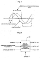
- a brushless-motor drive controller 400 includes a phase-current-instruction-signal generator 401, a phase-current controller 402, a motor driving circuit 403, and a rotor-position detector 404 as shown in Fig. 20.
- the phase-current-instruction-signal generator 401 corresponds to an exciting-phase-current instruction-signal generating means and the phase-current controller 402 and the motor driving circuit 403 correspond to an exciting-current control means.
- phase-current-instruction-signal generator 401 To the phase-current-instruction-signal generator 401, a motor-current instruction signal Iref from an external circuit (not shown) and a rotor-position signal RP from the rotor-position detector 404 are inputted.
- the phase-current-instruction-signal generator 401 generates respective exciting-phase-current instruction signals (iaref, ibref, and icref) of the exciting phases a, b, and c in accordance with the inputted signals.
- the phase-current controller 402 controls the detection of the respective exciting currents (ia, ib, and ic) of the exciting phases such that it detects also the two-phase current using a three-phase-current detection signal through the motor driving circuit 403 by current feedback control in accordance with the exciting-phase-current instruction signals (iaref, ibref, and icref) generated by the phase-current-instruction-signal generator 401.
- the motor driving circuit 403 is constructed of a total of six transistors (field effect transistors: FETs) T 1 to T 6 , three of which are arranged adjacent to the power source (upper stage) and three of which are arranged adjacent to the ground (lower stage).
- the six transistors are arranged such that corresponding upper and lower transistors are connected in series and the connections of the series transistor pairs (T 1 -T 2 , T 3 -T 4 , and T 5 -T 6 ) are connected to the external ends of the exciting coils of a three-phase brushless DC motor 410.
- Gate driving signals GT 1 to GT 6 of the transistors T 1 to T 6 are produced by the phase-current controller 402 through the phase-current-instruction-signal generator 401 in accordance with the rotor-position signal RP detected from the rotor-position detector 404.
- Commutation timing is generated from the rotor-position signal RP.
- the rotor-position signal RP is detected by the rotor-position detector 404 and is then sent to the phase-current-instruction-signal generator 401.
- the rotor-position detector 404 may be constructed of any of a hall element, a resolver, and an encoder.
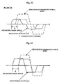
- Fig. 21 is a wave-form chart of an example of the motor-current instruction signal (Iref) and the exciting-phase-current instruction signals (iaref, ibref, and icref) in the exciting phases.
- the amplitudes of the energized exciting-phase-current instruction signals of the exciting phases are the same as that of the motor-current instruction signal, whose sign is opposite from that of the motor-current instruction signal and the amplitude of the nonenergized exciting-phase-current instruction signal of the exciting phase is zero.
- the nonenergized exciting-phase-current instruction signal iaref of a-phase as commutation phase rises from zero at, for example, an electrical angle of 30 degrees.
- the energized exciting-phase-current instruction signal icref of c-phase as commutation phase falls to zero.
- While the invention has been made to increase the rpm and to reduce the torque ripple in a high rpm range (low-torque load range), it is more efficient in a rated load range (normal rpm range) to use the motor current to generate torque than to advance the phase angle.
- control means from normal commutation control to any of the control means described in above paragraph 1. to 4. with shifting from the normal rpm range to a high rpm range.
- control means such that a reference angular speed is stored in the phase-current-instruction-signal generator 401 so that the control means is switched when the motor rotation speed (angular speed) exceeds a predetermined value and, when the actual angular speed exceeds the reference value, the control means is switched to any of the control means described in above paragraph 1. to 4. with a switching means (not shown).
- the use of the motor-wiring bus bars suitable for reducing the size of a motor, according to the invention offers the advantage of providing a compact motor.
- the use of the method for manufacturing the motor-wiring bus bars according to the invention offers the advantage of manufacturing a motor including economical motor-wiring bus bars in which the material is not wasted.
- the permanent magnet motor according to the invention for a permanent-magnet motor including a distributed-coil stator driven with a rectangular-wave current (120-degree energization), which requires low torque ripple, the combination of the angle widths of the teeth and the every other pole distributed winding (one coil for one slot) are adopted so that the phases of the voltage induced in the coils become equal in phase. This allows the torque ripple not to be increased, the torque constant not to be reduced, and the cogging torque to be significantly decreased. This offers a remarkable advantage of providing a permanent-magnet motor with low vibration and low noise.
- the slot opening width S between the teeth is set smaller than the space length G between the rotor and the stator core and larger than ⁇ G.
Landscapes
- Engineering & Computer Science (AREA)
- Power Engineering (AREA)
- Chemical & Material Sciences (AREA)
- Combustion & Propulsion (AREA)
- Transportation (AREA)
- Mechanical Engineering (AREA)
- Permanent Magnet Type Synchronous Machine (AREA)
- Windings For Motors And Generators (AREA)
- Manufacture Of Motors, Generators (AREA)
Abstract
A motor comprising a motor-wiring bus bar including a
plurality of annular ring conductors connecting lead wires
of the motor including a stator in which a plurality of stator
cores having the lead wires is arranged in a circle or
connecting the lead wires and a power line together and a
plurality of terminals attached to the ring conductors. The
ring conductors are different in diameter and arranged
concentrically on a same plane.
Description
The present invention relates to a motor, a method for
manufacturing the motor, and a motor drive controller. More
particularly, the invention relates to a motor including a
motor-wiring bus bar used for electrically connecting a lead
wire wound around a stator core and its manufacturing method,
relates to a permanent-magnet motor which requires low
cogging torque, low torque ripple, and high output with
compact size and which includes a rectangular-wave driven
distributed-coil stator, relates to a brushless DC motor used
in an electrically driven power steering system having no
motor lock and in which size reduction, low torque ripple,
and low cost are achieved, and relates to a brushless-motor
drive controller in which the toque ripple is reduced with
high rpm in a low-torque load range.
Bus bars have been used to connect lead wires
(hereinafter, referred to as coils) wound around motor stator
cores in view of assemble efficiency. For example, JP-A-2001-103700
and JP-A-2001-86695 describe that bus bars are
used because of their high connection efficiency and that the
bus bars are manufactured by stamping copper plates.
Referring to Figs. 1 and 2, the conventional motor-wiring
bus bar (hereinafter, simply referred to as a bus bar)
will be briefly described. Fig. 1 shows the mechanical
structure of a brushless DC motor. Fig. 2 shows the electrical
circuit thereof.
The mechanical structure will first be described.
Referring to Fig. 1, a stator 1000 includes stator cores 51-U,
51-V, 51-W, 52-U, 52-V, and 52-W corresponding to U-phase,
V-phase, and W-phase, respectively, and coils 101-U, 101-V,
101-W, 102-U, 102-V, and 102-W wound around the respective
cores. The connection of the coils will then be described.
For example, for the U-phase, one ends of the coils 101-U and
102-U are connected to a ring-shaped U-phase bus bar 1-U and
the other ends are connected to a ring-shaped N-phase bus bar
1-N. For the V-phase, one ends of the coils 101-V and 102-V
are connected to a ring-shaped V-phase bus bar 1-V and the
other ends are connected to a ring-shaped N-phase bus bar 1-N.
The coils of W-phase are also connected similarly. The
connection between the coils and the bus bars in Fig. 1 shows
electrical connection, in which specific connecting means are
not generally electrical wires but engagement of bus bars with
coils. Accordingly, since the connection with the ring-shaped
bus bars is easier than that with electrical wires,
it is useful in increasing assembly efficiency.
Referring now to Fig. 2, the electrical connection will
be described. A three-phase current is generated by an
inverter including a power source DC and switches SU, SV, SW,
SX, SY, and SZ, which is fed through power lines YU, YV, and
YW to the coils 101-U, 102-U, 101-V, 102-V, 101-W, and 102-W
of the stator 1000. In this example, since the coils are in
Y-connection, one ends of the coils are connected with the
U-, V-, W-phase bus bars 1-U, 1-V, and 1-W in correspondence
with the respective phases and all of the other ends of the
coils are connected with the neutral-point bus bar 1-N.
The operation of a motor with the mechanical and
electrical structure will be briefly described. A three-phase
current is fed to the coils of the motor by the inverter
including the DC power source and the switches. The current
is fed to the power lines YU, YV, and YW, the bus bars, and
the coils, which will be specifically described with the
U-phase as an example. The U-phase current flows through the
power line YU into a terminal 33-U of the U-phase bus bar 1-U,
passes through a U-phase ring conductor 2-U and is fed from
a terminal 31-U to the coil 101-U or from a terminal 32-U to
the coil 102-U. The current flowing through the coils 101-U
and 102-U flows into the bus bar 1-N and then flows from the
terminals of the bus bar 1-N into the V-phase coils 101-V and
102-V and the W-phase coils 101-W and 102-W. The currents
in the coils 101-V and 102-V join together through terminals
31-V and 32-V of the bus bar 1-V at the bus bar 1-V and returns
from a terminal 33-V through the power line YV to the DC power
source. Also the W-phase coil current passes through the bus
bar 1-W and returns to the DC power source. The three-phase
current flowing through the U-, V-, and W-phase coils
generates a rotary magnetic field to rotate a rotor (not
shown), thereby driving the motor.
As will be understood from the fact that the coil
currents flow into the bus bars to join together and flow out
therefrom, the bus bars are very important members to combine
the currents.
The conventional motors using the ring-shaped bus bar,
however, have a structural problem in achieving size
reduction. Specifically, referring to Fig. 3, since the stack
of ring-shaped bus bars 1-U, 1-V, 1-W, and 1-N is used, it
is four times as thick as that of the bus bar (four bus bars
of U-, V-, W-, and N-phase), having a problem in reducing the
size of the motor.
Also the method for manufacturing the motor including
the ring-shaped bus bars has the following problem: The ring
conductors have been made by stamping, thus having the problem
that the remaining of the stamped member is wasted.
The present invention has been made in view of the above
problems. Accordingly, it is a first object of the invention
to provide a motor including a motor-wiring bus bar suitable
for size reduction and a method for manufacturing a motor
including an economical motor-wiring bus bar which makes good
use of the member.
When low torque ripple is required for permanent-magnet
motors with conventional rectangular wave drive (120-degree
energization system), distributed winding has been adopted
for coils. In this case, the equation (1) holds from the
relationship between a possible number of poles, 2p, of the
motor including the distributed coils and the number of slots,
S
S/2 pm = integer
where m is the number of phases of the motor.
Since a cogging torque is in inverse proportion to the
least common multiple of the number of poles, 2p, and the
number of slots, S, it produces the problem of significantly
increasing the cogging torque.
In order to solve the above problems, a permanent-magnet
motor is provided which is disclosed in, for example, JP-A-10-126982.
The permanent-magnet motor achieves the
reduction of the cogging torque by arranging the teeth such
that the centers of the slot openings of the stator deviate
from the positions at equal intervals. More specifically,
the permanent-magnet motor includes annular permanent
magnets constituting M magnetic poles (M is an even number)
to construct a rotor and T teeth facing the permanent magnets
arranged at irregular intervals, a winding groove (slot)
between the teeth being wound with a coil, and the teeth being
joined to a yoke to construct a stator. The teeth are arranged
such that the centers of the slot openings of the stator
deviate from the position of regular intervals T by a
deviation of ±N × 180/{C(T/2 + 1)}, where C is the least common
multiple of the number M of the permanent magnets and the
number T of the teeth and N is an integer from 1 to T/2.
However, with the permanent-magnet motor disclosed in
the above-described JP-A-10-126982, the phases of voltage
induced by the coils deviate, so that harmonic component of
the voltage waveform induced between the coils are eliminated.
In other words, it has the problem of increasing the torque
ripple when the permanent magnetic motor is driven with a
rectangular-wave current.
The present invention has been made in view of the above
problems. Accordingly, it is a second object of the invention
to provide a permanent-magnet motor capable of achieving low
cogging torque, low torque ripple, and high output with
compact size, being driven with a rectangular-wave current,
and including a distributed-coil stator.
In an electrically driven power steering system that
energizes an automotive steering system with motor torque as
auxiliary, the driving force of the motor is applied to the
steering shaft or the rack shaft through a decelerator and
a transfer mechanism such as a gear and a belt to energize
it with an auxiliary load. Referring to Fig. 4, the simple
structure of the electrically driven power steering system
will be described. A shaft 102 of a steering wheel 101 is
joined to tie rods 106 of wheels through a reduction gear 103,
universal joints 104a and 104b, and a pinion rack mechanism
105. The shaft 102 includes a torque sensor 107 for sensing
the steering torque of the steering wheel 101. A motor 108
for applying an auxiliary power to the steering wheel 101 is
joined to the shaft 102 through the reduction gear 103. It
is important here that the motor 108 used for an important
safety component such as the electrically driven power
steering system is required to have significantly high
reliability.
However, the motor 108 actually has disadvantages, one
of which is that, with a brushless DC motor, foreign matter
is caught between the rotor and the stator to lock the motor.
Referring now to Fig. 5, the mechanism of the motor lock
will be described. Fig. 5(A) shows the longitudinal section
of the brushless DC motor and Fig. 5(B) shows the cross section
thereof. The brushless DC motor includes a rotor 9 having
a permanent magnet 9-1 mounted to the outer periphery and a
stator 10 wound with coils. The stator 10 includes a stator
core 12 having a plurality of teeth 11 and coils 14 wound
around slots 13 between the stator core 12 and the teeth 11.
Since the brushless DC motor generally uses sintered
permanent magnets for the rotor, the permanent magnets are
covered with a nonmagnetic metal plate or the like to prevent
locking even when the permanent magnets become chipped by
external impact. The stator has openings between the adjacent
teeth 11 to wind the coils 14 around the stator core 12. If
foreign matter 50 such as insulator chips or varnish for
hardening the coil enters the space between the rotor 9 and
the teeth 11 through the openings, there is a possibility that
the rotor is locked. An example of the method for preventing
the motor lock is adopting a divided core in which the inner
peripheries of the adjacent teeth are joined together. The
joining of the teeth, however, increases leakage of flux to
decrease the torque constant of the brushless DC motor, thus
reducing output. Also, it rapidly increases the ripple of
the counter electromotive voltage to increase torque ripple,
thus decreasing the operability of the electrically driven
power steering system. Another lock prevention method is
molding the stator and the coil and filling the adjacent
openings with resin, which has a disadvantage of increasing
the cost.
As described above, the sudden locking of the brushless
DC motor used as an important safety component such as the
electrically driven power steering system causes dangerous
car driving operation.
The invention has been made in view of the above problems.
Accordingly, it is a third object of the invention to provide
a brushless DC motor in which the motor output does not
decrease, the torque ripple is low, the cost is low, and the
motor is not locked.
The brushless motors used as the primary drive of
automotive power steering systems generally include three or
more exciting phases, which are driven with a
rectangular-wave exciting current.
For example, with a five-phase brushless motor, the
motor driving circuit rotates the rotor by exciting five-phase
(hereinafter, referred to as an a-phase to e-phase)
exciting coils a to e disposed to surround the outer periphery
of the rotor of the motor at an interval of 72 electrical
degrees with a rectangular-wave current, while switching the
coils sequentially phase by phase, by four-phase simultaneous
exciting under the control of a control circuit of a
microcomputer, etc. With the four-phase simultaneous
exciting, the motor current flows through four phases of the
five phases; the circuit is constructed such that the
resistances of the exciting coils are equal to feed the
current through the phases in good balance.
The motor driving circuits are generally constructed of
ten field effect transistors (FETs). The ten transistors
connect to the coil circuit of the motor such that two
corresponding transistors are connected in series to
construct five series transistor circuits, each of which is
connected between the positive and negative terminals of the
power source, and in which the connections of the two
transistors of each series transistor circuit are connected
to the external ends of the five star (Y)-connected exciting
coils a to e.
The direction and length of the exciting current
(rectangular wave) fed from the motor driving circuit to the
exciting coils relative to the rotation angle (electrical
angle) of the rotor is shown in Fig. 6 by way of example.
Specifically, the rotor is continuously rotated by
sequentially switching the exciting coils phase by phase
every 36 electrical degrees and exciting each phase coil
during 144 electrical degrees. Referring to Fig. 6, the
sections 0° ≤ < 36°, 36° ≤ < 72°, 72° ≤ < 108°, 108° ≤
< 144°, 144° ≤ < 180°, 180° ≤ < 216°, 216° ≤ < 252°, 252°
≤ < 288°, 288° ≤ < 324°, and 324° ≤ < 360° are indicated
by (1) to (10), respectively, where is the electrical angle.
In this example, the a-phase current flows in the plus
direction in sections (1) and (2), at zero in section (3),
in the minus direction in sections (4) to (7), at zero in
section (8), passes through sections (9) to (10), and again
flows in the plus direction in section (1). The b-phase
current flows in the plus direction in sections (1) to (4),
at zero in section (5), in the minus direction in sections
(6) to (9), at zero in section (10), and again flows in the
plus direction in section (1). The c-phase current flows in
the minus direction in section (1), at zero in section (2),
in the plus direction in sections (3) to (6), at zero in
section (7), passes through sections (8) to (10), and again
flows in the minus direction in section (1). The d-phase
current flows in the minus direction in sections (1) to (3),
at zero in section (4), in the plus direction in sections (5)
to (8), at zero in section (9) and again flows in the minus
direction in section (10). The e-phase current flows at zero
in section (1), in the minus direction in sections (2) to (5),
at zero in section (6), in the plus direction in sections (7)
to (10), and again becomes zero in section (1). Briefly, two
of the five exciting coils are switched in the opposite
direction at the boundaries (at the switching at every 36
electrical degrees) of the sections (1) to (10).
A brushless DC motor (BLDCM) and a permanent-magnet
synchronous motor (PMSM) are known as the brushless motor.
Examples of the former are disclosed in JP-A-11-356083 and
JP-A-2002-269569 which adopt commutation control. An example
of the latter is disclosed in JP-A-2000-201461.
Referring to Fig. 7, the brushless DC motor is lower in
rpm in a low-torque load range than the permanent-magnet
synchronous motor. However, it is possible to increase the
rpm by weakening field control in the low-torque load range.
However, this disadvantageously increases the torque ripple
with an increased rpm to cause a noise due to the torque
ripple.
With the permanent-magnet synchronous motor, the
weakening field control facilitates the increase in rpm in
the low-torque load range; however, decreases the rpm in a
rated load range, being inferior to the brushless DC motor
in terms of size reduction and high output of the motor in
the rated load range.
The electrically driven power steering system requires
a compact, high-output, low-torque-ripple, low-noise motor
and controller and also high rpm during low torque loading
(for example, in emergency).
The invention has been made in view of the above problems.
Accordingly, it is a fourth object of the invention to provide
a brushless-motor drive controller for a brushless DC motor
in which high rpm is achieved and torque ripple is reduced
during low torque loading.
The present invention relates to a motor including a
motor-wiring bus bar, comprising: a plurality of annular ring
conductors connecting lead wires of said motor or connecting
said lead wires and a power line together; and a plurality
of terminals attached to said ring conductors. The first
object of the invention is achieved by setting said ring
conductors different in diameter and arranging said ring
conductors concentrically in a same plane, wherein: said
motor includes a stator in which a plurality of stator cores
wound with said lead wires is arranged in a circle.
It is also achieved by constructing said ring conductor
from part of a annulus ring, or covering said ring conductors
with insulating coating, or making that a current to said lead
wires of said motor has multiple phases and color of said lead
wire is the same as color of said ring conductor which is equal
in phase with said lead wire.
The invention relates to a method for manufacturing a
motor including a motor-wiring bus bar, characterized in that
said motor comprising: a plurality of annular ring conductors
connecting lead wires of said motor or connecting said lead
wires and a power line together; and a plurality of terminals
attached to said ring conductors. The first object of the
invention is achieved by making that said motor includes a
stator in which a plurality of stator cores wound with said
lead wires is arranged in a circle; and said ring conductor
is formed by transforming a rectangular plate into annular
shape or slicing a cylinder.
The present invention relates to a permanent-magnet
motor capable of achieving low cogging torque, low torque
ripple, and high output with compact size and including a
distributed-coil stator driven with a rectangular-wave
current. The second object of the invention is achieved by
a three-phase permanent-magnet motor, comprising: a
distributed-coil stator, wherein: said motor is driven with
a rectangular-wave current; S/2 mp = 1 holds (where S is number
of slots, m is number of phases of said motor, and 2p (p ≥
2) is number of poles); and when p is an even number, a cycle
of angle width of teeth is expressed as 360/S × 4 and, when
p is an odd number, said cycle of angle width of teeth is
expressed as 360/S × 6.
The second object of the invention is advantageously
achieved by making that in one of said cycle of angle width
of teeth, when p is an even number, kind of angle width of
teeth is set to three and, when p is an odd number, said kind
of angle width of teeth is set to four; and for combination,
angle widths of odd teeth are set to be equal and angle widths
of even teeth are set to be different, or making that in one
of said cycle of angle widths of teeth, when p is an even number,
kind of angle width of teeth is set to three and, when p is
an odd number, said kind of angle width of teeth is set to
four; and for combination, angle widths of even teeth are set
to be equal and angle widths of odd teeth are set to be
different, or adopting every other pole winding (one coil for
one slot) as method of winding so that voltages induced in
coils are equal in phase, or making that when is equally
spaced angle width and α is available said angle width of teeth,
range of α is expressed as a · ≤ α ≤ b · , where coefficients
a and b are determined by torque constant or reduction ratio
of cogging-torque.
The present invention relates to a brushless DC motor.
The third object of the invention is achieved by a brushless
DC motor, comprising: a rotatable rotor in which permanent
magnet is fixed around outer periphery; and a stator core
formed by a plurality of teeth holding coil around cylindrical
inner periphery, wherein: S < G holds, where S is slot opening
width between teeth and G is space length between said rotor
and said stator core.
It is also achieved by limiting relationship between
said slot opening width S and said space length G to αG < S,
where α is determined from torque constant of said brushless
DC motor or content of ripple of counter electromotive voltage
(0 < α < 1).
The present invention relates to a brushless-motor
drive controller in which high rpm is achieved and torque
ripple is reduced in a low torque load range. The fourth
object of the invention is achieved by a brushless-motor drive
controller having a plurality of exciting phases, comprising:
a exciting-phase-current-instruction-signal generating
means for generating exciting-phase-current instruction
signal for each exciting phase; and a exciting-current
control means for controlling exciting current for each
exciting phase by current feedback control in accordance with
said exciting-phase-current instruction signal generated by
said exciting-phase-current-instruction-signal generating
means, wherein: said exciting-phase-current-instruction-signal
generating means advances electrical angle of said
exciting-phase-current instruction signal having shape other
than a rectangular wave by a predetermined angle, so that
comparing to driving speed range during drive control of
rectangular-wave exciting current, driving speed range of
said brushless-motor is expanded.
The fourth object of the invention is advantageously
achieved by a brushless-motor drive controller having a
plurality of exciting phases, comprising: a exciting-phase-current-instruction-signal
generating means for
generating exciting-phase-current instruction signal for
each exciting phase; and a exciting-current control means for
controlling exciting current for each exciting phase by
current feedback control in accordance with said
exciting-phase-current instruction signal generated by said
exciting-phase-current-instruction-signal generating means,
wherein: said exciting-phase-current-instruction-signal
generating means advances electrical angle of said
exciting-phase-current instruction signal in which rates of
change in exciting current of two commutation phases agree
with each other during commutation by a predetermined angle
to achieve weakening field.
The fourth object of the invention is advantageously
achieved by a brushless-motor drive controller having a
plurality of exciting phases, comprising: a exciting-phase-current-instruction-signal
generating means for
generating exciting-phase-current instruction signal for
each exciting phase; and a exciting-current control means for
controlling exciting current for each exciting phase by
current feedback control in accordance with said
exciting-phase-current instruction signal generated by said
exciting-phase-current-instruction-signal generating means,
wherein: said exciting-phase-current-instruction-signal
generating means advances electrical angle of said
exciting-phase-current instruction signal which is a
trapezoidal-wave or a sine-wave by a predetermined angle to
achieve weakening field.
The fourth object of the invention is advantageously
achieved by a brushless-motor drive controller having a
plurality of exciting phases, comprising: a exciting-phase-current-instruction-signal
generating means for
generating exciting-phase-current instruction signal for
each exciting phase; and a exciting-current control means for
controlling exciting current for each exciting phase by
current feedback control in accordance with said
exciting-phase-current instruction signal generated by said
exciting-phase-current-instruction-signal generating means,
wherein: said exciting-phase-current-instruction-signal
generating means generates said exciting-phase-current
instruction signal including phase-angle advancing from a
induced electromotive force, a output torque, and a rotation
speed of said brushless motor.
The fourth object of the invention is advantageously
achieved by a brushless-motor drive controller, wherein a
rotation angle of rotor of said brushless motor is given by
an angle estimation signal estimated from a rotor-position
signal detected by a rotor-position detector, motor current,
etc. or a brushless-motor drive controller, characterized in
that when rotation speed of said motor exceeds a predetermined
value, said controller shifts to weakening field control by
phase-angle advancing.
Preferred embodiments of the present invention will be
described hereinafter with reference to the drawings.
Referring to Fig. 8, a first embodiment of a motor
according to the invention will be described. The ring
conductors 2-U, 2-V, 2-W, and 2-N are manufactured with
different diameters, for example, with the ring diameter
decreased in order of, e.g., U-phase, V-phase, W-phase, and
N-phase, to which projecting terminals 31-U, 31-V, 31-W, 31-N
and so on are mounted to the peripheries thereof; thus, the
phase bus bars 1-U, 1-V, 1-W, and 1-N are completed. The bus
bars 1-U, 1-V, 1-W, and 1-N are then concentrically assembled
in one plane of the ring conductors. The extracting ends of
the coils are extracted in correspondence with the terminal
positions of the bus bars, which are connected together as
shown in Figs. 1 and 2 of the description of the background
art. With the connection, the electrical connection is
exactly the same as that of the background art, so that the
motor can maintain the same performance as that of the
background art.
The use of the bus bars of this embodiment eliminates
the necessity of stacking the bus bars, thus remarkably
reducing the height. In this embodiment, the height is only
a quarter of that of the conventional stacked bus bars as shown
in Fig. 3, remarkably reducing the height to achieve a compact
motor.
Referring now to Fig. 9, a second embodiment of a motor
will be described. Fig. 9(A) shows an assembly of bus bars
according to the second embodiment in perspective view. Fig.
9(B) shows the assembled bus bars in plan view. The bus bars
do not necessarily require to have a perfect ring (annular)
shape as electrically connecting member, even a part of ring
shape functions as electrically connecting member. The bus
bar is hereinafter referred to as a ring-piece bus bar. Also
in this case, ring-piece bus bars 1-U-A, 1-V-A, 1-W-A, and
1-N-A are manufactured with different diameters and
concentrically assembled in one plane, as in the first
embodiment. With this embodiment, the coil extracting
positions of the coils are limited because the ring conductors
are smaller than those of the embodiment of Fig. 8. The
ring-piece bus bars are therefore suitable for motors having
small number of coils.
Also with this embodiment, the height of the assembled
ring-piece bus bars can be smaller than that of the
conventional stacked one, offering an advantage in reducing
the size of motors and a great economical effect of decreasing
the number of components.
The bus bar is not generally single but multiple, which
are generally arranged in close vicinity, so that they may
come in contact with one another. The contact would cause
electrical shortage to damage the motor function. It is thus
considered that an insulation space is provided or an
insulator is placed therebetween, which will decrease working
efficiency. Accordingly, applying an insulator to the ring
conductors in advance will prevent electrical shortage even
if the bas bars come in contact with one another, improving
assembly efficiency and eliminating useless space to reduce
the size of the motor.
An increase in the number of the stator cores increases
the number of phase coils connected to the ring conductors.
The increase in the number of the connected wires raises the
possibility of miswiring. Thus, the color of the coil of
individual phase and the ring conductor of the same phase as
that of the coil are colored in the same color. For example,
when the respective coils 101-U, 101-V, and 101-W of U-phase,
V-phase, and W-phase are colored in red, blue, and white,
respectively, and the bus bars 1-U, 1-V, 1-W, and 1-N of the
U-phase, V-phase, W-phase, and N-phase are colored in red,
blue, white, and green, respectively, the coils with the same
phase can be connected together at a glance. More
specifically, the lead wire of the red coil 101-U adjacent
to the power source connects to the red bus bar 1-U, that of
the blue coil 101-V connects to the blue bus bar 1-V, and that
of the white coil 101-W connects to the white bus bar 1-W.
The lead wires of the coils of all the phases adjacent to the
neutral point connect to the green bus bar 1-N.
Accordingly, since they can be assembled without
caution to miswiring, which offers advantages of increasing
working efficiency and the quality of the motor because no
miswired motor is manufactured. For coloring, it is
sufficient to color only part of the coils and bus bars if
the phases can be discriminated to prevent miswiring. When
the entire ring conductors are colored, providing insulating
function to the paint for coloring eliminates the possibility
of electrical shortage and miswiring, thus greatly improving
assembly efficiency.
The method will be described for manufacturing the motor
including the motor-wiring bus bars according to the
invention.
Fig. 10(A) shows a copper rectangular plate 500 serving
as the material of the ring conductors, which is transformed
into annular shape to form a ring conductor 2. The ring
conductor 2 includes projecting terminals 31, 32, and 33 for
electrically connecting to the coils 100-U and 101-U and the
power line YU around the periphery to form a bus bar 1
constructed of a ring conductor and terminals, shown in Fig.
10(B). The ring conductor 2 can also be manufactured without
using the rectangular plate. Referring to Fig. 11, when a
copper cylinder 600 is sliced into the ring conductor 2, to
which the projecting terminals 31, 32, and 33 are attached
for connecting coils to the ring conductor, the bus bar 1 is
completed. Also in this case, the member is not wasted,
different from stamping manufacture. The thickness of the
rectangular plate and the sliced cylinder is determined
depending on the capacity of the current flowing through the
ring conductor 2.
As described above, by the method of manufacturing the
motor including the bus bar using the ring conductor made of
the rectangular plate or the cylinder, according to the
invention, less member is wasted, offering an economical
advantage of increasing yields different from the
conventional stamping manufacture of motor including the bus
bar using the ring conductor.
A preferred embodiment of a permanent-magnet motor
according to the invention will now be described with
reference to the drawings. In this description, the angle
widths of the teeth mean an angle between the centers of
adjacent slot openings. Specifically, they are T1 to T12 in
Figs. 12, 13, 15 and 16 and T1 to T18 in Figs. 17 and 14.
This invention will first be described for an embodiment
applied to a permanent-magnet motor including four-pole
12-slot distributed coils. In this embodiment, since the
number S of slots is 12 and the number 2p of poles is 4, p
becomes 2.
Fig. 15 shows a conventional permanent-magnet motor
including four-pole 12-slot distributed coils in sectional
view. As shown in Fig. 15, a ring-shaped permanent magnet
201 includes four magnetic poles at regular intervals of 90
degrees to construct a rotor 200. Twelve teeth 203 facing
the permanent magnet 201 are arranged at regular intervals,
winding grooves (slots) between the adjacent teeth 203 are
wound with coils and the teeth 203 are held by a yoke 204 to
construct a stator 202. The rotor 200 rotates around a shaft
(not shown) by a rotating magnetic field generated from the
current flowing through the coils of the stator 202.
Fig. 16 shows the development of the magnetic poles and
the teeth 203 of the conventional permanent-magnet motor of
Fig. 15. As shown in Fig. 16, the four magnetic poles of the
permanent-magnet motor are developed in order of N, S, N, and
S. The 12 teeth 203 are also developed, in which the angles
widths T1 to T12 for the 12 teeth 203 are equal.
As shown in Figs. 15 and 16, the positions where the
pitch of the magnetic poles (the switching between the N-pole
and the S-pole) and the pitch of the teeth 203 (the angle
widths of the teeth) agree with each other are four positions,
A, B, C, and D, surrounded by a rectangular frame. Briefly,
when the pitch of the magnetic poles is expressed in
mechanical angle, four positions, 0 degree, 90 degrees, 180
degrees, and 270 degrees are given. The pitch of the teeth
203 is expressed as 12 positions of 0 degree, 30 degrees, 60
degrees, 90 degrees, 120 degrees, 150 degrees, 180 degrees,
210 degrees, 240 degrees, 270 degrees, 300 degrees, and 330
degrees. In other words, for the conventional permanent-magnet
motor shown in Fig. 15, all the four positions in the
pitch of the magnetic poles agree with the pitch of the teeth
203 in angle.
Since the conventional permanent-magnet motor of Fig.
15 adopts adjacent-pole wiring in which two coils are wound
for one slot, it includes four coils for each phase.
Specifically, the U-phase winding is constructed of four
coils, U1, U2, U3, and U4, the V-phase winding is constructed
of four coils, V1, V2, V3, and V4, and the W-phase winding
is constructed of four coils, W1, W2, W3, and W4. Fig. 15
clearly shows that two coils are wound for one slot.
Cogging torque generates by the change in magnetic
energy. In other words, the more the positions where the pitch
of the magnetic poles and the pitch of the teeth agree to each
other, the more the phases of the change in magnetic energy
agree to each other, so that the change in magnetic energy
increases, thus increasing the cogging torque. Thus, the
conventional permanent-magnet motor shown in Figs. 15 and 16
has as many as four positions where the pitch of the magnetic
poles and the pitch of the teeth agree to each other, posing
the problem of increasing the cogging torque.
Fig. 12 shows a sectional view of the permanent-magnet
motor including four-pole 12-slot distributed coils (a first
embodiment), according to the invention. As shown in Fig.
12, a ring-shaped permanent magnet 201 includes four magnetic
poles at regular intervals of 90 degrees to construct a rotor
200. Twelve teeth 203 facing the permanent magnet 201 are
held in a yoke 204 to construct a stator 202, winding grooves
(slots) between the adjacent teeth 203 are wound with coils.
The rotor 200 rotates around a shaft (not shown) by a rotating
magnetic field generated from the current flowing through the
coils of the stator 202.
Fig. 13 shows the development of the magnetic poles and
the teeth 203 of the permanent-magnet motor of Fig. 12. As
shown in Fig. 13, the permanent-magnet motor of the invention
includes four magnetic poles, which are developed in order
of N, S, N, and S. The 12 teeth 203 are also developed. The
angle widths of the 12 teeth 203 have a cycle. The cycle of
the angle widths of the teeth 203 is expressed as equations
(2) and (3).
when p is an even number,the cycle of the angle width of the teeth = 360/S × 4
and when p is an odd number,
the cycle of the angle width of the teeth = 360/S × 6
where S is the number of slots and 2p is the number of poles.
when p is an even number,
Accordingly, in this embodiment, 360/12 × 4 = 120 holds,
so that the cycle of the angle widths of the teeth 203 is 120
degrees. Specifically, this embodiment has a total of three
cycles: the angle widths of the teeth, T1, T2, T3, and T4,
construct one cycle, the angle widths of the teeth, T5, T6,
T7, and T8, construct another cycle, and the angle widths of
the teeth, T9, T10, T11, and T12, construct still another
cycle.
In short, with the permanent-magnet motor including
four-pole 12-slot distributed coils (the first embodiment)
according to the invention, since the cycle of the angle
widths of the teeth is 120 degrees, the phase deviates from
the pitch of the magnetic poles, 90 degrees. This allows the
cogging frequency higher to thereby reducing the cogging
torque.
In the permanent-magnet motor including four-pole
12-slot distributed coils according to the invention, shown
in Fig. 12, the kind of the angle widths of the teeth is set
to three when p is an even number, while it is set to four
when p is an odd number in the cycle of the angle width of
one tooth (the kind of the angle widths of the teeth is three
in this embodiment). For the combination, the angle widths
of the odd teeth are set to be equal and the angle widths of
the even teeth are set to be different.
Specifically, referring to the development plan of Fig.
13, T1 = T3 and T2 ≠ T4 hold in the cycle of teeth angle widths,
T1, T2, T3, and T4, while T5 = T7 and T6 ≠ T8 hold in the cycle
of teeth angle widths, T5, T6, T7, and T8. Also T9 = T11 and
T10 ≠ T12 hold in the cycle of teeth angle widths, T9, T10,
T11, and T12. Of course, T1 = T3 = T5 = T7 = T9 = T11, T2
= T6 = T10, and T4 = T8 = T12 hold.
As shown in the development plan of Fig. 13, for example,
the phase difference between the coils U1 and U2 is expressed
as equation (4)
phase difference (U1, U2)
= T2/2 + T3 + T4 + T5 + T6 + T7 + T8/2
= 3/2 × (2 × T1 + T2 + T4) = 180 degrees
Since a phase difference of 360 electrical degrees is
given from the equation (4), the voltages induced in the coils
U1 and U2 are equal in phase.
In the permanent-magnet motor including four-pole
12-slot distributed coils according to the invention, shown
in Fig. 12, setting T1 > T2 and T1 > T4 increases the flux
linkage of the coils, thus offering the advantage of
increasing the torque constant. As shown in the development
plan of Fig. 13, the position where the pitch of the magnetic
poles (the switching of N-pole and S-pole) and the pitch of
the teeth (angle widths of the teeth) agree with each other
is only one, point A surrounded by the rectangular frame.
Since the permanent-magnet motor including four-pole
12-slot distributed coils according to the invention, shown
in Fig. 12, adopts every-other-pole wiring in which one coil
is wound for one slot, it includes two coils for each phase.
Specifically, the U-phase winding is constructed of two coils,
U1 and U2, the V-phase winding is constructed of two coils,
V1 and V2, and the W-phase winding is constructed of two coils,
W1 and W2. Fig. 12 clearly shows that one coil is wound for
one slot.
As described above, since the permanent-magnet motor
including distributed coils according to the invention adopts
the combination of the angle widths of the teeth and the
every-other-pole distributed winding (one coil for one slot),
the phases of the voltage induced in the coils do not deviate,
thus not increasing torque ripple. In the permanent-magnet
motor including distributed coils according to the invention,
the range of the available angle width α of the tooth is
expressed in terms of the angle width at equal intervals as
the expression (5)
a · ≤ α ≤ b ·
where a and b are coefficients determined depending on the
torque constant or the reduction ratio of the cogging-torque.
While the permanent-magnet motor including four-pole
12-slot distributed coils (the first embodiment) has been
described in the above description, a permanent-magnet motor
including six-pole 18-slot distributed coils (a second
embodiment) will now be described.
Fig. 17 shows the development of the magnetic poles and
the teeth of a conventional permanent-magnet motor including
six-pole 18-slot distributed coils. As shown in Fig. 17, the
six magnetic poles of the conventional permanent-magnet motor
are developed in order of N, S, N, S, N, and S. Eighteen teeth
are also developed, in which all the angle widths T1 to T18
for the 18 teeth are equal.
As shown in Fig. 17, the positions where the pitch of
the magnetic poles (the switching between the N-pole and the
S-pole) and the pitch of the teeth (the angle widths of the
teeth) agree with each other are six positions, A, B, C, D,
E, and F, surrounded by a rectangular frame. Briefly, when
the pitch of the magnetic poles is expressed in mechanical
angle, six positions of 0 degree, 60 degrees, 120 degrees,
180 degrees, 240 degrees, and 300 degrees are given. The pitch
of the teeth is expressed as 18 positions of 0 degree, 20
degrees, 40 degrees, 60 degrees, 80 degrees, 100 degrees, 120
degrees, 140 degrees, 160 degrees, 180 degrees, 200 degrees,
220 degrees, 240 degrees, 260 degrees, 280 degrees, 300
degrees, 320 degrees, and 340 degrees. In other words, with
the conventional permanent-magnet motor including six-pole
18-slot distributed coils, all the six positions of the pitch
of the magnetic poles and the pitch of the teeth agree with
each other in angle.
Since the conventional permanent-magnet motor
including six-pole 18-slot distributed coils adopts
adjacent-pole wiring in which two coils are wound for one slot,
it includes six coils for each phase. Specifically, the
U-phase winding is constructed of six coils, U1, U2, U3, U4,
U5, and U6, the V-phase winding is constructed of six coils,
V1, V2, V3, V4, V5, and V6, and the W-phase winding is
constructed of six coils, W1, W2, W3, W4, W5, and W6. For
example, since the phase difference between the coils U1 and
U2 is 60 degM (mechanical angle), i.e. 180 degE (electrical
angle), reversing the winding direction brings that the
voltages induced in the coils become equal in phase.
Fig. 14 shows the development of the magnetic poles and
the teeth of the permanent-magnet motor including six-pole
18-slot distributed coils according to the invention. In this
embodiment, since the number S of slots is 18 and the number
2p of poles is 6, p becomes 3. As shown in Fig. 14, the six
magnetic poles of the permanent-magnet motor are developed
in order of N, S, N, S, N, and S. The 18 teeth are also
developed. In the invention, the cycle of the angle widths
of the 18 teeth is expressed as equations (6) and (7).
when p is an even number,the cycle of the angle width of the teeth = 360/S × 4
and when p is an odd number,
the cycle of the angle width of the teeth = 360/S × 6
where S is the number of slots and 2p is the number of poles.
when p is an even number,
Accordingly, in this embodiment, 360/18 x 6 = 120 holds,
so that the cycle of the angle widths of the teeth is 120
degrees. Specifically, this embodiment has a total of three
cycles: the angle widths of the teeth, T1, T2, T3, T4, T5,
and T6 construct one cycle, the angle widths of the teeth,
T7, T8, T9, T10, T11, and T12 construct another cycle, and
the angle widths of the teeth, T13, T14, T15, T16, T17, and
T18 construct still another cycle. In short, with the
permanent-magnet motor including six-pole 18-slot
distributed coils according to the invention, since the cycle
of the angle width of the teeth is 120 degrees, the phase
deviates from the pitch of the magnetic poles, 60 degrees.
This allows the cogging frequency higher, thereby reducing
cogging torque.
In the permanent-magnet motor including six-pole 18-slot
distributed coils according to the invention, in the
cycle of the angle width of one tooth, when p is an even number,
the kind of the angle width of the teeth is set to three, while
when p is an odd number, it is set to four (the kind of the
angle widths of the teeth is four in this embodiment); for
the combination, the angle widths of odd teeth are set to be
equal and the angle widths of even teeth are set to be
different.
Specifically, as shown in Fig. 14, T1 = T3 = T5 and T2
≠ T4 ≠ T6 hold in the cycle of teeth angle widths, T1, T2, T3,
T4, T5, and T6, while T7 = T9 = T11 and T8 ≠ T10 ≠ T12 hold
in the cycle of teeth angle widths, T7, T8, T9, T10, T11, and
T12. Also T13 = T15 = T17 and T14 ≠ T16 ≠ T18 hold in the cycle
of teeth angle widths, T13, T14, T15, T16, T17, and T18. Of
course, T1 = T3 = T5 = T7 = T9 = T11 = T13 = T15 = T17, T2
= T8 = T14, T4 = T10 = T16, and T6 = T12 = T18 hold.
The positions where the pitch of the magnetic poles (the
switching between the N-pole and the S-pole) and the pitch
of the teeth (the angle widths of the teeth) agree with each
other are three positions, A, B, and C, surrounded by a
rectangular frame.
As shown in the development plan of Fig. 14, for example,
the phase difference between the coils U1 and U2 is expressed
as equation (8).
phase difference (U1, U2)
= T2/2 + T3 + T4 + T5 + T6 + T7 + T8/2
= 3 × T1 + T2 + T4 + T6 = 120 degM (mechanical angle)
= 360 degE (electrical angle)
From the equation (8), the voltages induced in the coils are
equal in phase.
Since the permanent-magnet motor including six-pole
18-slot distributed coils according to the invention adopts
every-other-pole wiring in which one coil is wound for one
slot, it includes three coils for each phase. Specifically,
the U-phase winding is constructed of three coils, U1, U2,
and U3, the V-phase winding is constructed of three coils,
V1, V2, and V3, and the W-phase winding is constructed of three
coils, W1, W2, and W3.
While the permanent-magnet motor including four-pole
12-slot distributed coils (the first embodiment) and the
permanent-magnet motor including six-pole 18-slot
distributed coils (the second embodiment) have been described
in the above, the invention is not limited to those but may
be applied to a three-phase permanent-magnet motor driven
with a rectangular-wave current and including a
distributed-coil stator, in which the equation S/2 mp = 1 (p
≥ 2) holds. For the combination of the kinds of the angle
widths of the teeth (three kinds when p is an even number and
four kinds when p is an odd number), the angle widths of even
teeth may be set to be equal and the angle widths of odd teeth
may be set to be different.
A brushless DC motor according to the invention will now
be specifically described with reference to the drawings.
A first embodiment of the brushless DC motor will be
described. Fig. 18 shows the brushless DC motor of the
invention in cross section, which includes the same
components as those of the known art of Fig. 5(B). An
important point in Fig. 18 is not the components but their
dimensional relationship. Specifically, the opening width
S of the slot 13 i.e. the opening width S between the teeth
11, is smaller than the space length G between the rotor 9
and the stator core 10. Briefly, it is that the relationship
S < G holds. When the relationship holds, the foreign matter
50, such as varnish for hardening the coils 14, does not enter
from the slots 13 through the openings between the teeth 11
(the opening width S) into the space between the rotor 9 (the
permanent magnet 9-1 in the strict sense) and the teeth 11
to lock the rotation of the rotor 9. This is because the size
of the foreign matter 50 passing through the openings between
the teeth 11 (the opening width S) is, of course, smaller than
the opening width S, whereas the space length G between the
rotor 9 and the teeth 11 is larger than the opening width S,
so that the size of the foreign matter 50 is naturally smaller
than the space length G. Thus, the foreign matter 50 is not
caught in the space to lock the rotation of the rotor 9.
In general, the smaller the space length G of motors,
the more effective magnetic flux is. From this point of view,
the smaller the space length G the better; but actually, the
space length G is of the order of one to three percent of the
outside diameter of the rotor because of the mechanical
structure limitation. Assuming a brushless DC motor with an
output of 200 W to 800 W by way of specific example, the rotor
has an outside diameter of approximately 30 to 60 mm and a
space length G of 0.3 to 1.8 mm. The space length G, however,
is desirably 0.6 mm or more in consideration of the
reinforcement of the field magnet from the point of view of
reliability. Specifically, the space length G takes on the
above value; however, when the opening width S is smaller than
the space length G (S < G), the rotor is not locked with the
foreign matter discharged from the slot. Accordingly, this
offers the advantages of preventing the brushless DC motor
of an electrically driven power steering system from being
suddenly locked not to ensure safety.
A second embodiment of the brushless DC motor will then
be described. Too small slot opening width S decreases the
torque constant of the brushless DC motor in relation to
leakage flux to reduce the output and rapidly increases the
ripple of the counter electromotive voltage to lower the
operability of the steering. Thus, lower limit of slot
opening width S must be determined. Fig. 19 shows a graph
of the change in torque constant (expressed as Kt in Fig. 19)
of the brushless DC motor and the ripple of the counter
electromotive voltage generated in the coils (expressed as
emf ripple in Fig. 19) by computer simulation when the slot
opening width S in certain shape is varied from zero to the
space length G. When the slot opening width S is decreased,
i.e. the space between the teeth 11 is decreased, an
inflection point at which the torque constant rapidly
decreases, or the content of the ripple rapidly increases
appears near the point at which the opening width S is 20
percent of the space length G. This is because, referring
to Fig. 18, although the magnetic flux normally passes through
the magnetic path indicated by A, a leakage flux circuit where
the magnetic flux passes through the magnetic path indicated
by B generates with a reduced opening width between the teeth
11, so that the effective magnetic flux in the magnetic path
A decreases. The leakage flux passing through the magnetic
path B also becomes a contributing factor that decreases the
torque constant and increases the ripple of the counter
electromotive voltage. When the opening width S becomes
smaller than αG, where α is the coefficient and G is the space
length, the ripple of the counter electromotive voltage
rapidly increases.
The means for determining the coefficient α is
determined by electromagnetic field simulation in
consideration of the structure. This is because the ratio
of the quantity of the magnetic flux passing through the
magnetic path A to the quantities of the magnetic flux passing
through the magnetic path B has a correlation. Specifically,
the ratio of the amounts of magnetic flux passing through the
magnetic paths A and B is determined depending on complicated
factors including the ratio of the magnetic permeability
determined depending on the material of the stator core 12
to the magnetic permeability of air, the shape, namely, the
shape of the stator core 12 and the shape of the teeth 11,
and the degrees of the projections of the corners of the teeth
11. It is therefore impossible to determine the ratio of the
quantities of magnetic flux in the magnetic paths by a simple
expression; in practice, it is determined by computer
simulation in consideration of the material and structure of
the stator core 12 and magnetic flux density. The value of
the coefficient α is thus determined by computer simulation.
One example of the actual simulation is shown in Fig. 19,
described above. In this case, when the opening width S
becomes approximately 20 percent of the space length G, the
ripple of the counter electromotive voltage rapidly increases
to significantly lower the operability of the electrically
driven steering. With this embodiment, therefore, when the
opening width S is set to 20 percent or more of the space length
G, the torque constant does not decrease, the ripple of the
counter electromotive voltage is brought within the allowable
range, so that it is expected that the operability of the
electrically driven steering is not lowered.
The invention has the advantages of eliminating a
decrease in output due to a decrease in torque constant and
also the problem of decreasing the operability of the steering
because of increased torque ripple and preventing the motor
lock of the brushless DC motor, different from the method of
the known art in which a divided core is adopted, and in which
the inner peripheries of the adjacent teeth are joined
together. Since molding is not adopted in the invention, the
motor lock of the brushless DC motor can be prevented at low
cost.
A preferred embodiment of a brushless-motor drive
controller according to the invention will now be
specifically described. Although the embodiment is described
with an application to a three-phase brushless DC motor by
way of example, the invention is not limited to that but may
be applied to another multiple-exciting-phase (for example,
five-phase) brushless motor. An exciting-phase-current
instruction signal may be produced by either hardware or
software. In this embodiment, the exciting-phase-current
instruction signal is produced by software.
A brushless-motor drive controller 400 according to the
invention includes a phase-current-instruction-signal
generator 401, a phase-current controller 402, a motor
driving circuit 403, and a rotor-position detector 404 as
shown in Fig. 20. The phase-current-instruction-signal
generator 401 corresponds to an exciting-phase-current
instruction-signal generating means and the phase-current
controller 402 and the motor driving circuit 403 correspond
to an exciting-current control means.
To the phase-current-instruction-signal
generator 401, a motor-current instruction signal Iref from
an external circuit (not shown) and a rotor-position signal
RP from the rotor-position detector 404 are inputted. The
phase-current-instruction-signal generator 401 generates
respective exciting-phase-current instruction signals
(iaref, ibref, and icref) of the exciting phases a, b, and
c in accordance with the inputted signals. The phase-current
controller 402 controls the detection of the respective
exciting currents (ia, ib, and ic) of the exciting phases such
that it detects also the two-phase current using a three-phase-current
detection signal through the motor driving
circuit 403 by current feedback control in accordance with
the exciting-phase-current instruction signals (iaref, ibref,
and icref) generated by the phase-current-instruction-signal
generator 401.
The motor driving circuit 403 is constructed of a total
of six transistors (field effect transistors: FETs) T1 to T6,
three of which are arranged adjacent to the power source
(upper stage) and three of which are arranged adjacent to the
ground (lower stage). The six transistors are arranged such
that corresponding upper and lower transistors are connected
in series and the connections of the series transistor pairs
(T1-T2, T3-T4, and T5-T6) are connected to the external ends of
the exciting coils of a three-phase brushless DC motor 410.
Gate driving signals GT1 to GT6 of the transistors T1 to T6 are
produced by the phase-current controller 402 through the
phase-current-instruction-signal generator 401 in
accordance with the rotor-position signal RP detected from
the rotor-position detector 404.
Commutation timing is generated from the rotor-position
signal RP. The rotor-position signal RP is detected by the
rotor-position detector 404 and is then sent to the
phase-current-instruction-signal generator 401. The
rotor-position detector 404 may be constructed of any of a
hall element, a resolver, and an encoder.
Fig. 21 is a wave-form chart of an example of the
motor-current instruction signal (Iref) and the exciting-phase-current
instruction signals (iaref, ibref, and icref)
in the exciting phases. As shown in the drawing, during no
commutating period, the amplitudes of the energized
exciting-phase-current instruction signals of the exciting
phases are the same as that of the motor-current instruction
signal, whose sign is opposite from that of the motor-current
instruction signal and the amplitude of the nonenergized
exciting-phase-current instruction signal of the exciting
phase is zero.
As shown in Fig. 21, upon commutation, the nonenergized
exciting-phase-current instruction signal iaref of a-phase
as commutation phase rises from zero at, for example, an
electrical angle of 30 degrees. The energized exciting-phase-current
instruction signal icref of c-phase as
commutation phase falls to zero.
With the above structure, a method will be described
hereinafter for achieving high rpm of the brushless DC motor
in a low-torque load range and reducing an increase in torque
ripple therewith.
While the invention has been made to increase the rpm
and to reduce the torque ripple in a high rpm range (low-torque
load range), it is more efficient in a rated load range
(normal rpm range) to use the motor current to generate torque
than to advance the phase angle.
Accordingly, it is preferable to switch the control
means from normal commutation control to any of the control
means described in above paragraph 1. to 4. with shifting from
the normal rpm range to a high rpm range.
It is also preferable to switch the control means such
that a reference angular speed is stored in the phase-current-instruction-signal
generator 401 so that the control
means is switched when the motor rotation speed (angular
speed) exceeds a predetermined value and, when the actual
angular speed exceeds the reference value, the control means
is switched to any of the control means described in above
paragraph 1. to 4. with a switching means (not shown).
As set forth hereinabove, the use of the motor-wiring
bus bars suitable for reducing the size of a motor, according
to the invention, offers the advantage of providing a compact
motor. The use of the method for manufacturing the
motor-wiring bus bars according to the invention offers the
advantage of manufacturing a motor including economical
motor-wiring bus bars in which the material is not wasted.
With the permanent magnet motor according to the
invention, for a permanent-magnet motor including a
distributed-coil stator driven with a rectangular-wave
current (120-degree energization), which requires low torque
ripple, the combination of the angle widths of the teeth and
the every other pole distributed winding (one coil for one
slot) are adopted so that the phases of the voltage induced
in the coils become equal in phase. This allows the torque
ripple not to be increased, the torque constant not to be
reduced, and the cogging torque to be significantly decreased.
This offers a remarkable advantage of providing a
permanent-magnet motor with low vibration and low noise.
According to the brushless DC motor of the invention,
the slot opening width S between the teeth is set smaller than
the space length G between the rotor and the stator core and
larger than αG. This offers the advantages that the
operability of the steering of an electrically driven power
steering system is not lowered, output is not reduced, and
the motor lock of the brushless DC motor is prevented at low
cost.
With the brushless-motor drive controller according to
the invention, a compact brushless motor with high output and
low torque ripple can be achieved, so that high rpm with low
noise can be achieved in a low-torque load range.
Claims (19)
- A motor including a motor-wiring bus bar, comprising:a plurality of annular ring conductors connecting lead wires of said motor or connecting said lead wires and a power line together;
anda plurality of terminals attached to said ring conductors,
wherein:said motor includes a stator in which a plurality of stator cores wound with said lead wires is arranged in a circle;
andsaid ring conductors are different in diameter and is arranged concentrically in a same plane. - A motor including a motor-wiring bus bar according to Claim 1, wherein said ring conductor is constructed from part of a annulus ring.
- A motor including a motor-wiring bus bar according to Claim 1 or 2, wherein said ring conductors are covered with insulating coating.
- A motor including a motor-wiring bus bar according to any one of Claims 1 - 3, wherein a current to said lead wires of said motor has multiple phases
and
color of said lead wire is the same as color of said ring conductor which is equal in phase with said lead wire. - A method for manufacturing a motor including a motor-wiring bus bar, characterized in that
said motor comprising:a plurality of annular ring conductors connecting lead wires of said motor or connecting said lead wires and a power line together;
anda plurality of terminals attached to said ring conductors,
wherein:said motor includes a stator in which a plurality of stator cores wound with said lead wires is arranged in a circle;
andsaid ring conductor is formed by transforming a rectangular plate into annular shape or slicing a cylinder. - A three-phase permanent-magnet motor, comprising:wherein:a distributed-coil stator,said motor is driven with a rectangular-wave current;S/2 mp = 1 holds (where S is number of slots, m is number of phases of said motor, and 2p (p ≥ 2) is number of poles);
andwhen p is an even number, a cycle of angle width of teeth is expressed as 360/S × 4 and, when p is an odd number, said cycle of angle width of teeth is expressed as 360/S × 6. - A permanent-magnet motor according to Claim 6,
wherein:in one of said cycle of angle width of teeth, when p is an even number, kind of angle width of teeth is set to three and, when p is an odd number, said kind of angle width of teeth is set to four;
andfor combination, angle widths of odd teeth are set to be equal and angle widths of even teeth are set to be different. - A permanent-magnet motor according to Claim 6,
wherein:in one of said cycle of angle widths of teeth, when p is an even number, kind of angle width of teeth is set to three and, when p is an odd number, said kind of angle width of teeth is set to four;
andfor combination, angle widths of even teeth are set to be equal and angle widths of odd teeth are set to be different. - A permanent-magnet motor according to Claim 6, wherein, method of winding is every other pole winding (one coil for one slot) so that voltages induced in coils are equal in phase.
- A permanent-magnet motor according to Claim 7 or 8, wherein, when is equally spaced angle width and α is available said angle width of teeth, range of α is expressed as a · ≤ α ≤ b · , where coefficients a and b are determined by torque constant or reduction ratio of cogging-torque.
- A brushless DC motor, comprising:wherein:a rotatable rotor in which permanent magnet is fixed around outer periphery;
anda stator core formed by a plurality of teeth holding coil around cylindrical inner periphery,S < G holds, where S is slot opening width between teeth and G is space length between said rotor and said stator core. - A brushless DC motor according to Claim 11, wherein relationship between said slot opening width S and said space length G is limited to αG < S, where α is determined from torque constant of said brushless DC motor or content of ripple of counter electromotive voltage (0 < α < 1).
- A brushless-motor drive controller having a plurality of exciting phases, comprising:wherein:a exciting-phase-current-instruction-signal generating means for generating exciting-phase-current instruction signal for each exciting phase;
anda exciting-current control means for controlling exciting current for each exciting phase by current feedback control in accordance with said exciting-phase-current instruction signal generated by said exciting-phase-current-instruction-signal generating means,said exciting-phase-current-instruction-signal generating means advances electrical angle of said exciting-phase-current instruction signal having shape other than a rectangular wave by a predetermined angle, so that comparing to driving speed range during drive control of rectangular-wave exciting current, driving speed range of said brushless-motor is expanded. - A brushless-motor drive controller having a plurality of exciting phases, comprising:wherein:a exciting-phase-current-instruction-signal generating means for generating exciting-phase-current instruction signal for each exciting phase;
anda exciting-current control means for controlling exciting current for each exciting phase by current feedback control in accordance with said exciting-phase-current instruction signal generated by said exciting-phase-current-instruction-signal generating means,said exciting-phase-current-instruction-signal generating means advances electrical angle of said exciting-phase-current instruction signal in which rates of change in exciting current of two commutation phases agree with each other during commutation by a predetermined angle to achieve weakening field. - A brushless-motor drive controller having a plurality of exciting phases, comprising:wherein:a exciting-phase-current-instruction-signal generating means for generating exciting-phase-current instruction signal for each exciting phase;
anda exciting-current control means for controlling exciting current for each exciting phase by current feedback control in accordance with said exciting-phase-current instruction signal generated by said exciting-phase-current-instruction-signal generating means,said exciting-phase-current-instruction-signal generating means advances electrical angle of said exciting-phase-current instruction signal which is a trapezoidal-wave by a predetermined angle to achieve weakening field. - A brushless-motor drive controller having a plurality of exciting phases, comprising:wherein:a exciting-phase-current-instruction-signal generating means for generating exciting-phase-current instruction signal for each exciting phase;
anda exciting-current control means for controlling exciting current for each exciting phase by current feedback control in accordance with said exciting-phase-current instruction signal generated by said exciting-phase-current-instruction-signal generating means,said exciting-phase-current-instruction-signal generating means advances electrical angle of said exciting-phase-current instruction signal which is a sine-wave by a predetermined angle to achieve weakening field. - A brushless-motor drive controller having a plurality of exciting phases, comprising:wherein:a exciting-phase-current-instruction-signal generating means for generating exciting-phase-current instruction signal for each exciting phase;
anda exciting-current control means for controlling exciting current for each exciting phase by current feedback control in accordance with said exciting-phase-current instruction signal generated by said exciting-phase-current-instruction-signal generating means,said exciting-phase-current-instruction-signal generating means generates said exciting-phase-current instruction signal including phase-angle advancing from a induced electromotive force, a output torque, and a rotation speed of said brushless motor. - A brushless-motor drive controller according to Claim 17, wherein a rotation angle of rotor of said brushless motor is given by an angle estimation signal estimated from a rotor-position signal detected by a rotor-position detector, motor current, etc..
- A brushless-motor drive controller, characterized in that when rotation speed of said motor exceeds a predetermined value, said controller shifts to weakening field control by phase-angle advancing according to any one of Claims 13 - 18.
Applications Claiming Priority (9)
| Application Number | Priority Date | Filing Date | Title |
|---|---|---|---|
| JP2002212381 | 2002-07-22 | ||
| JP2002212381 | 2002-07-22 | ||
| JP2002229989 | 2002-08-07 | ||
| JP2002229989 | 2002-08-07 | ||
| JP2002260726 | 2002-09-06 | ||
| JP2002260726 | 2002-09-06 | ||
| JP2002290692 | 2002-10-03 | ||
| JP2002290692 | 2002-10-03 | ||
| PCT/JP2003/009018 WO2004010562A1 (en) | 2002-07-22 | 2003-07-16 | Motor, method of manufacturing motor, and driving control device for motor |
Publications (2)
| Publication Number | Publication Date |
|---|---|
| EP1542339A1 true EP1542339A1 (en) | 2005-06-15 |
| EP1542339A4 EP1542339A4 (en) | 2008-07-02 |
Family
ID=30773598
Family Applications (1)
| Application Number | Title | Priority Date | Filing Date |
|---|---|---|---|
| EP03741421A Withdrawn EP1542339A4 (en) | 2002-07-22 | 2003-07-16 | Motor, method of manufacturing motor, and driving control device for motor |
Country Status (6)
| Country | Link |
|---|---|
| US (1) | US7180217B2 (en) |
| EP (1) | EP1542339A4 (en) |
| JP (1) | JPWO2004010562A1 (en) |
| CN (1) | CN100411279C (en) |
| AU (1) | AU2003281557A1 (en) |
| WO (1) | WO2004010562A1 (en) |
Cited By (2)
| Publication number | Priority date | Publication date | Assignee | Title |
|---|---|---|---|---|
| EP1648074A3 (en) * | 2004-10-15 | 2006-06-07 | Minebea Co., Ltd. | Electrical machine, in particular a DC motor |
| EP1985522A1 (en) * | 2007-04-24 | 2008-10-29 | ZF-Lenksysteme GmbH | Protective device for a power steering mechanism |
Families Citing this family (51)
| Publication number | Priority date | Publication date | Assignee | Title |
|---|---|---|---|---|
| EP1505711B1 (en) * | 2003-08-02 | 2010-05-19 | ebm-papst St. Georgen GmbH & Co. KG | Electric motor |
| JP4287418B2 (en) * | 2005-09-02 | 2009-07-01 | 本田技研工業株式会社 | Motor connection structure |
| WO2007052385A1 (en) * | 2005-11-01 | 2007-05-10 | Matsushita Electric Industrial Co., Ltd. | Motor and method of producing stator used for the motor |
| JP5176283B2 (en) * | 2006-03-30 | 2013-04-03 | 日産自動車株式会社 | Rotating electrical machine bus bar insulation structure |
| DE102006021898A1 (en) * | 2006-05-11 | 2007-11-22 | Zf Friedrichshafen Ag | Stator for an electric machine |
| CN101694954B (en) * | 2006-07-04 | 2012-07-25 | 本田技研工业株式会社 | Motor stator structure |
| JP4138823B2 (en) * | 2006-07-04 | 2008-08-27 | 本田技研工業株式会社 | Motor stator structure |
| US8164289B2 (en) * | 2006-10-16 | 2012-04-24 | Mitsuba Corporation | Brushless motor and control method of brushless motor |
| JP4936117B2 (en) * | 2006-12-12 | 2012-05-23 | 日本電産株式会社 | motor |
| JP4586034B2 (en) * | 2007-03-16 | 2010-11-24 | 株式会社日立製作所 | Motor driving semiconductor device, three-phase motor having the same, motor driving device and fan motor |
| CN100568670C (en) * | 2007-03-28 | 2009-12-09 | 上海电气集团上海电机厂有限公司 | The structure and method of connecting the conductive ring at the end of the stator of the high-power variable-frequency AC motor |
| JP4743167B2 (en) | 2007-05-29 | 2011-08-10 | トヨタ自動車株式会社 | Terminal module for rotating electric machine and rotating electric machine |
| DE102007025971B4 (en) * | 2007-06-04 | 2018-06-07 | Seg Automotive Germany Gmbh | Electric machine with hybrid-excited rotor |
| CN100521501C (en) * | 2007-09-30 | 2009-07-29 | 奇瑞汽车股份有限公司 | Torsion management method of mixed power electric motor |
| DE102007055754B4 (en) * | 2007-12-11 | 2021-05-12 | Robert Bosch Gmbh | Electric servo motor |
| JP5335265B2 (en) * | 2008-03-28 | 2013-11-06 | 三洋電機株式会社 | Electric motor |
| JP5311103B2 (en) * | 2008-06-17 | 2013-10-09 | 株式会社ジェイテクト | Vehicle steering system |
| KR101015053B1 (en) * | 2009-02-16 | 2011-02-16 | 현담산업 주식회사 | Connecting Molding for Three-Phase Motor Winding Automation |
| JP2010200400A (en) * | 2009-02-23 | 2010-09-09 | Nippon Densan Corp | Stator, bus bar unit, motor, and power steering device |
| WO2011031686A1 (en) * | 2009-09-08 | 2011-03-17 | Green Ray Technologies Llc | Electric machines including stator modules |
| JP2011062000A (en) * | 2009-09-11 | 2011-03-24 | Denso Corp | Controller of ac motor |
| JP5477091B2 (en) * | 2010-03-18 | 2014-04-23 | 株式会社Ihi | Rotating machine |
| CN101780811A (en) * | 2010-03-22 | 2010-07-21 | 苏州萨克汽车科技有限公司 | Automobile assisted power steering system |
| JP5842361B2 (en) * | 2010-10-29 | 2016-01-13 | 日本電産株式会社 | Motor and motor manufacturing method |
| KR101268589B1 (en) * | 2011-12-26 | 2013-05-28 | 전자부품연구원 | Apparatus for motor using a variable connecting wire |
| KR101342290B1 (en) * | 2012-06-28 | 2013-12-16 | 엘지이노텍 주식회사 | Motor |
| KR101992687B1 (en) | 2012-06-28 | 2019-06-25 | 엘지이노텍 주식회사 | Motor |
| US10277099B2 (en) * | 2013-09-02 | 2019-04-30 | Mitsubishi Electric Corporation | Synchronous motor |
| FR3018964B1 (en) * | 2014-03-24 | 2016-03-04 | Valeo Equip Electr Moteur | INTERCONNECTION ELEMENT FOR CONNECTING STATOR COILS |
| DE102014113489A1 (en) * | 2014-09-18 | 2016-03-24 | Feaam Gmbh | Electric machine |
| DE102014221188A1 (en) * | 2014-10-20 | 2016-04-21 | Bayerische Motoren Werke Aktiengesellschaft | Switching ring arrangement for an electrical machine |
| US9698642B1 (en) * | 2015-09-02 | 2017-07-04 | X Development Llc | Motor with multi-phase windings and series-stacked inverter |
| US10404124B2 (en) * | 2015-10-28 | 2019-09-03 | Mitsubishi Electric Corporation | Rotary electric machine |
| JP6472570B2 (en) * | 2016-03-14 | 2019-02-20 | 三菱電機株式会社 | Electric motor control system and electric power steering apparatus provided with the same |
| EP3431365B1 (en) * | 2016-03-14 | 2019-11-27 | Mitsubishi Electric Corporation | Three-phase redundant motor device for electric power steering devices |
| CN106329852A (en) * | 2016-10-21 | 2017-01-11 | 珠海格力节能环保制冷技术研究中心有限公司 | Stator punching sheet design method, stator punching sheet, stator iron core and motor |
| DE102017211168A1 (en) * | 2017-06-30 | 2019-01-03 | Zf Friedrichshafen Ag | Stator interconnection device for a rotating electrical machine |
| WO2019028048A1 (en) | 2017-07-31 | 2019-02-07 | Pentair Flow Technologies, Llc | Ring-style terminal block and submersible pump with ring-style terminal block |
| CN208571864U (en) * | 2017-07-31 | 2019-03-01 | 日本电产东测有限公司 | Motor |
| US10618423B2 (en) * | 2017-09-15 | 2020-04-14 | Ford Global Technologies, Llc | Isolated dual bus hybrid vehicle drivetrain |
| DE102018200995A1 (en) * | 2018-01-23 | 2019-07-25 | Robert Bosch Gmbh | A method of operating a steering system with a compensation device for reducing a torque ripple of a three-phase machine |
| DE102018202408A1 (en) * | 2018-02-16 | 2019-08-22 | Bühler Motor GmbH | STATOR WITH A WINDING SWITCHING |
| FR3086814B1 (en) * | 2018-09-28 | 2020-10-30 | Sonceboz Mechatronics Boncourt Sa | ELECTRIC ACTUATOR |
| JP6611892B1 (en) * | 2018-10-30 | 2019-11-27 | 三菱電機株式会社 | Electric braking device |
| CN111130293A (en) * | 2018-11-01 | 2020-05-08 | 长鹰信质科技股份有限公司 | Brushless single-wire motor winding structure for electric vehicle |
| JP7270783B2 (en) * | 2019-08-20 | 2023-05-10 | 安徽威▲靈▼汽▲車▼部件有限公司 | Busbars, busbar bodies, motors, electric power steering systems and vehicles |
| JP7441072B2 (en) * | 2020-02-25 | 2024-02-29 | 株式会社Subaru | stator |
| TWI778515B (en) * | 2021-02-05 | 2022-09-21 | 姚立和 | Wiring frame, motor stator, and motor applying them |
| CN117856499A (en) * | 2022-09-30 | 2024-04-09 | 日本电产株式会社 | Motor |
| KR102961627B1 (en) * | 2022-10-26 | 2026-05-07 | 효성전기주식회사 | Brushless motor manufacturing method for air compressor of hydrogen car applying multi-winding of 2 poles and 6 slot |
| JP2025023736A (en) * | 2023-08-04 | 2025-02-17 | 株式会社ミツバ | Motor |
Family Cites Families (22)
| Publication number | Priority date | Publication date | Assignee | Title |
|---|---|---|---|---|
| JPS6048374U (en) * | 1983-09-05 | 1985-04-05 | 株式会社東芝 | Motor with slot iron core |
| US5097166A (en) * | 1990-09-24 | 1992-03-17 | Reuland Electric | Rotor lamination for an AC permanent magnet synchronous motor |
| JPH0622486A (en) * | 1992-07-03 | 1994-01-28 | Kokusan Denki Co Ltd | Armature for rotating electric machine |
| JP3372068B2 (en) * | 1992-11-10 | 2003-01-27 | 株式会社東芝 | Rotating electric machine |
| JPH06233483A (en) * | 1993-01-29 | 1994-08-19 | Honda Motor Co Ltd | Connection structure of coil winding in stator |
| ES2111917T3 (en) * | 1993-03-19 | 1998-03-16 | Daikin Ind Ltd | DIRECT CURRENT MOTOR WITHOUT SUPER HIGH SPEED BRUSHES. |
| JPH0767306A (en) * | 1993-08-24 | 1995-03-10 | Canon Electron Inc | Electromagnetic rotating machine |
| JP3236198B2 (en) * | 1995-08-23 | 2001-12-10 | 日本サーボ株式会社 | Control device for brushless motor |
| WO1997031422A1 (en) * | 1996-02-23 | 1997-08-28 | Matsushita Electric Industrial Co., Ltd. | Motor |
| JPH10126982A (en) * | 1996-10-24 | 1998-05-15 | Matsushita Electric Ind Co Ltd | Permanent magnet motor |
| JP3430839B2 (en) * | 1997-03-03 | 2003-07-28 | 松下電器産業株式会社 | Stator connection structure |
| JP3844577B2 (en) * | 1997-12-05 | 2006-11-15 | 日産自動車株式会社 | Rotating machine |
| JPH11178298A (en) * | 1997-12-15 | 1999-07-02 | Toshiba Corp | Stator core of permanent magnet type motor and permanent magnet type motor |
| JP3298508B2 (en) | 1998-06-09 | 2002-07-02 | 日本精工株式会社 | Motor drive control device |
| JP4306851B2 (en) | 1999-01-06 | 2009-08-05 | 本田技研工業株式会社 | Lead angle correction method for magnet type brushless motor |
| DE19920127C2 (en) * | 1999-05-03 | 2001-05-31 | Mannesmann Sachs Ag | Stator for an electrical machine and method for producing a stator |
| JP2001086695A (en) * | 1999-09-16 | 2001-03-30 | Toyoda Mach Works Ltd | motor |
| JP2001103700A (en) | 1999-09-30 | 2001-04-13 | Toyota Motor Corp | Motor stator |
| WO2001029953A1 (en) * | 1999-10-21 | 2001-04-26 | Emerson Electric Co. | Shroud for covering a stator winding head |
| EP1107429A3 (en) * | 1999-12-01 | 2005-06-15 | Kabushiki Kaisha MORIC | Stator winding connections of a rotating electrical machine |
| JP3574046B2 (en) * | 2000-06-08 | 2004-10-06 | 三洋電機株式会社 | Drive device for brushless motor |
| JP4779233B2 (en) | 2001-06-04 | 2011-09-28 | 日本精工株式会社 | Brushless motor drive control device |
-
2003
- 2003-07-16 EP EP03741421A patent/EP1542339A4/en not_active Withdrawn
- 2003-07-16 JP JP2005505165A patent/JPWO2004010562A1/en active Pending
- 2003-07-16 WO PCT/JP2003/009018 patent/WO2004010562A1/en not_active Ceased
- 2003-07-16 AU AU2003281557A patent/AU2003281557A1/en not_active Abandoned
- 2003-07-16 CN CNB038174618A patent/CN100411279C/en not_active Expired - Fee Related
-
2005
- 2005-01-24 US US11/039,914 patent/US7180217B2/en not_active Expired - Lifetime
Cited By (3)
| Publication number | Priority date | Publication date | Assignee | Title |
|---|---|---|---|---|
| EP1648074A3 (en) * | 2004-10-15 | 2006-06-07 | Minebea Co., Ltd. | Electrical machine, in particular a DC motor |
| EP1985522A1 (en) * | 2007-04-24 | 2008-10-29 | ZF-Lenksysteme GmbH | Protective device for a power steering mechanism |
| JP2008265740A (en) * | 2007-04-24 | 2008-11-06 | Zf Lenksysteme Gmbh | Protection device for power steering |
Also Published As
| Publication number | Publication date |
|---|---|
| US20050189828A1 (en) | 2005-09-01 |
| US7180217B2 (en) | 2007-02-20 |
| EP1542339A4 (en) | 2008-07-02 |
| JPWO2004010562A1 (en) | 2005-11-17 |
| CN100411279C (en) | 2008-08-13 |
| AU2003281557A1 (en) | 2004-02-09 |
| CN1672308A (en) | 2005-09-21 |
| WO2004010562A1 (en) | 2004-01-29 |
Similar Documents
| Publication | Publication Date | Title |
|---|---|---|
| US7180217B2 (en) | Motor, method for manufacturing motor, and motor drive controller | |
| KR101015916B1 (en) | Electric motor | |
| US9564779B2 (en) | Permanent magnet motor | |
| EP2412091B1 (en) | Electric motor system | |
| EP0295718B1 (en) | Method for winding a motor with armature teeths and field magnet | |
| JP3748387B2 (en) | Permanent magnet type rotating electrical machine and power generation system and drive system using the same | |
| EP3576293B1 (en) | Electric drive device and electric power steering device | |
| WO2007123107A1 (en) | Motor | |
| EP1968081A1 (en) | Brushless motor and electric power steering device having brushless motor | |
| CN108778895B (en) | Three-phase dual motor device for electric power steering | |
| JP6227712B2 (en) | Rotating electric machine and vehicle equipped with the rotating electric machine | |
| JP2008301652A (en) | Permanent magnet type rotating electric machine and electric power steering apparatus using the same | |
| JP2001268879A (en) | Brushless motor and drive control device therefor | |
| WO2003047072A1 (en) | Brushless dc motor and circuit for controlling the same | |
| JPWO2017168574A1 (en) | Electric motor | |
| JPH04289759A (en) | Brushless motor | |
| JP2003088078A (en) | Brushless DC motor | |
| JP3117164B2 (en) | Permanent magnet rotating electric machine, control method and control device thereof, and electric vehicle using the same | |
| CN101780811A (en) | Automobile assisted power steering system | |
| JP3457076B2 (en) | Electric motor | |
| CN120226232A (en) | Rotating electric machines | |
| CN119137840A (en) | Permanent magnet synchronous motor | |
| JP4147826B2 (en) | Brushless motor drive control device | |
| CN201863884U (en) | Automobile power-assisted steering system | |
| US20230198452A1 (en) | Power conversion apparatus, motor, and electric power steering apparatus |
Legal Events
| Date | Code | Title | Description |
|---|---|---|---|
| PUAI | Public reference made under article 153(3) epc to a published international application that has entered the european phase |
Free format text: ORIGINAL CODE: 0009012 |
|
| 17P | Request for examination filed |
Effective date: 20050204 |
|
| AK | Designated contracting states |
Kind code of ref document: A1 Designated state(s): AT BE BG CH CY CZ DE DK EE ES FI FR GB GR HU IE IT LI LU MC NL PT RO SE SI SK TR |
|
| AX | Request for extension of the european patent |
Extension state: AL LT LV MK |
|
| DAX | Request for extension of the european patent (deleted) | ||
| A4 | Supplementary search report drawn up and despatched |
Effective date: 20080529 |
|
| STAA | Information on the status of an ep patent application or granted ep patent |
Free format text: STATUS: THE APPLICATION IS DEEMED TO BE WITHDRAWN |
|
| 18D | Application deemed to be withdrawn |
Effective date: 20080827 |