EP1542089A2 - Image forming apparatus and toner supply method - Google Patents
Image forming apparatus and toner supply method Download PDFInfo
- Publication number
- EP1542089A2 EP1542089A2 EP04027758A EP04027758A EP1542089A2 EP 1542089 A2 EP1542089 A2 EP 1542089A2 EP 04027758 A EP04027758 A EP 04027758A EP 04027758 A EP04027758 A EP 04027758A EP 1542089 A2 EP1542089 A2 EP 1542089A2
- Authority
- EP
- European Patent Office
- Prior art keywords
- developing
- developing device
- toner density
- color
- developer
- Prior art date
- Legal status (The legal status is an assumption and is not a legal conclusion. Google has not performed a legal analysis and makes no representation as to the accuracy of the status listed.)
- Granted
Links
Images


Classifications
-
- G—PHYSICS
- G03—PHOTOGRAPHY; CINEMATOGRAPHY; ANALOGOUS TECHNIQUES USING WAVES OTHER THAN OPTICAL WAVES; ELECTROGRAPHY; HOLOGRAPHY
- G03G—ELECTROGRAPHY; ELECTROPHOTOGRAPHY; MAGNETOGRAPHY
- G03G15/00—Apparatus for electrographic processes using a charge pattern
- G03G15/01—Apparatus for electrographic processes using a charge pattern for producing multicoloured copies
- G03G15/0105—Details of unit
- G03G15/0121—Details of unit for developing
-
- G—PHYSICS
- G03—PHOTOGRAPHY; CINEMATOGRAPHY; ANALOGOUS TECHNIQUES USING WAVES OTHER THAN OPTICAL WAVES; ELECTROGRAPHY; HOLOGRAPHY
- G03G—ELECTROGRAPHY; ELECTROPHOTOGRAPHY; MAGNETOGRAPHY
- G03G15/00—Apparatus for electrographic processes using a charge pattern
- G03G15/06—Apparatus for electrographic processes using a charge pattern for developing
- G03G15/08—Apparatus for electrographic processes using a charge pattern for developing using a solid developer, e.g. powder developer
- G03G15/0822—Arrangements for preparing, mixing, supplying or dispensing developer
- G03G15/0848—Arrangements for testing or measuring developer properties or quality, e.g. charge, size, flowability
- G03G15/0849—Detection or control means for the developer concentration
- G03G15/0853—Detection or control means for the developer concentration the concentration being measured by magnetic means
-
- G—PHYSICS
- G03—PHOTOGRAPHY; CINEMATOGRAPHY; ANALOGOUS TECHNIQUES USING WAVES OTHER THAN OPTICAL WAVES; ELECTROGRAPHY; HOLOGRAPHY
- G03G—ELECTROGRAPHY; ELECTROPHOTOGRAPHY; MAGNETOGRAPHY
- G03G15/00—Apparatus for electrographic processes using a charge pattern
- G03G15/06—Apparatus for electrographic processes using a charge pattern for developing
- G03G15/08—Apparatus for electrographic processes using a charge pattern for developing using a solid developer, e.g. powder developer
- G03G15/0822—Arrangements for preparing, mixing, supplying or dispensing developer
- G03G15/0848—Arrangements for testing or measuring developer properties or quality, e.g. charge, size, flowability
- G03G15/0849—Detection or control means for the developer concentration
- G03G15/0855—Detection or control means for the developer concentration the concentration being measured by optical means
-
- G—PHYSICS
- G03—PHOTOGRAPHY; CINEMATOGRAPHY; ANALOGOUS TECHNIQUES USING WAVES OTHER THAN OPTICAL WAVES; ELECTROGRAPHY; HOLOGRAPHY
- G03G—ELECTROGRAPHY; ELECTROPHOTOGRAPHY; MAGNETOGRAPHY
- G03G2215/00—Apparatus for electrophotographic processes
- G03G2215/01—Apparatus for electrophotographic processes for producing multicoloured copies
- G03G2215/0167—Apparatus for electrophotographic processes for producing multicoloured copies single electrographic recording member
- G03G2215/0174—Apparatus for electrophotographic processes for producing multicoloured copies single electrographic recording member plural rotations of recording member to produce multicoloured copy
- G03G2215/0177—Rotating set of developing units
Definitions
- the present invention relates to an image forming apparatus such as a color printer, a color copier, etc. to form color images on sheets of paper and a toner supply method.
- a color laser printer is known as an image forming apparatus to form a color image on a sheet of paper as disclosed in the Japanese Patent Application Publication No. 11-84801.
- This color laser printer has an image carrier on which latent images are formed by the exposure, plural developing devices to develop this latent images by supply specified color developers, a intermediate transfer belt to transfer color developer images formed on the image carrier by overlapping each other, a transferring device to transfer the color developer images transferred by superposing each other on the intermediate transfer belt, and a transfer unit to transfer color developer images formed on a intermediate transfer belt en block on paper, and a cassette housing a number of sheets of paper.
- a yellow, magenta and cyan developing devices are set in a developing device rotary arranged rotatably at the side of the image carrier, and a black developing device is a separate unit from the developing device rotary and arranged opposite to the rotary from above the image carrier.
- the developing device rotary houses 3 developing devices side by side in its peripheral direction and opposes a specific color developing device to the image carrier by rotating.
- the intermediate transfer belt is brought to contact the image carrier from below.
- An image receiving medium (paper) taken out of the cassette is conveyed on a conveying path extending nearly in the horizontal direction under the intermediate transfer belt and passes the intermediate transfer belt. At this time, color developer images transferred on the intermediate transfer belt in the overlapped state are transferred on the image receiving medium (paper) in a lump.
- a black developing device As a black developing device is arranged above the image carrier, a developer undesirably scattering from this developing device drops on the image carrier. When a developer falls on the image carrier, this developer is transferred on a sheet by way of a intermediate transfer belt and an image becomes worse (dirty).
- the developing devices disclosed here use single-component developers, respectively and it is not necessary to check toner density of a developer in respective developing device.
- 2-component developing system has merits in the image quality such as wider expression of gradation and in particular, excellent reproduction of bright halftone.
- a 2-component developing system is higher than a single-component developer and scattering of toners around characters, very small dots and thin lines is less than a single-component developing system.
- consumables of 2-component developing system are usable for longer than a single-component developing system; for example, developing devices can be used up to the service life of the main body and a running cost per sheet of paper is cheaper than that of a single-component developing system.
- many image forming apparatus in the 2-component developing system are provided in the market.
- the image forming apparatus in this example has black, cyan, magenta and yellow developing devices. These devices are in the rotatable structure and supported by the main body. Each of the color developing devices is movable to a position to visualize a latent image formed on the photosensitive drum according to need. Developers retained in these developing devices are two-compoent developer and it is necessary to detect density of each toner and control to supply to maintain toners always at specified densities.
- the image forming apparatus has the black, cyan, magenta and yellow developing portions, which are supported rotatably by the main body and therefore, it is difficult to use magnetic sensors that are normally used for detecting toner density of two-compoent developer. This is because it is difficult to install a means to transmit an output signal from a sensor to the main body.
- a density sensor is arranged at the downstream side in the peripheral direction of the photosensitive drum of the developing device to detect density of an image developed on the photosensitive drum.
- the supply of a toner to the developing device, change of developing conditions, etc. are executed according to the density signal from the density sensor, and the toner density of 2-component developer is controlled to maintain always at a specified toner density.
- An object of the present invention is to provide an image forming apparatus using a two-component developer and a toner supply and control method to prevent defective images generated by adhesion of developers without lowering the print speed performance for detecting toner density and undesirably consuming toner.
- an image forming apparatus which comprises an image carrier on which plural latent images are formed repeatedly; a color developing device which has plural first developing units containing specified color developers arranged side by side in a rotating direction and are able to rotate the plural first developing units to oppose to the image carrier selectively and develop the latent images by supplying specified color developers; a second developing device arranged along the outer surface of the image carrier at a position differing from the position where the first developing units of the color developing device is opposed to the image carrier, and opposes to the image carrier and develops the latent image by supplying a specified color developer; a first toner density detecting measns for detecting a toner density of the developers contained in the first developing units, wherein the developers are two-compoent developer comprising at least non-magnetic toner and magnetic carrier; and a second toner density detecting means for detecting the toner densitiy of the developers contained in the second developing device of which detecting method differs from the first toner
- a toner supply method of an image forming apparatus which has an image carrier on which plural latent images are formed repeatedly, plural first developing units containing specified color developers arranged in the rotating direction, color developing units provided to arrange the plural first developing units selectively to oppose to the image carrier and develop the latent images by specific color developers, and a second developing unit arranged at a position opposing to the image carrier at a position differing from the position the first developing units of the color developing device are opposed to the image carrier and supply a specific color developer to develop the latent images
- the method comprising: detecting toner density of two-component developer contained in the first developing units arranged opposing to next to the applicable first developing unit when the color developing device is rotated and the first developing unit is opposed to the image carrier; storing the toner density detected value of the first developing units; and controlling the toner supply to the applicable first developing units based on the stored toner density detected value of the first developing unit when-the color developing device is rotated and the next first developing unit is
- FIG. 1 schematically shows the inner internal structure of a color copier 1 as an image forming apparatus involved in the embodiment of the present invention.
- the color copier 1 has a scanner unit 2, an image forming unit 4, and a paper supply unit 6.
- the scanner unit 2 illuminates an original set on a document table (not shown), leads the reflecting light from the original to a light receiving element through plural optical members, and outputs image data by the photoelectric transfer.
- the image forming unit 4 outputs an image based on image data region from the original by the scanner unit 2 or input from an external device (not shown) on a paper P (an image receiving medium).
- the paper supply unit 6 supplied a paper P to the image forming unit 4.
- the color copier 1 has a housing 3 containing the above-mentioned units. On the right side surface of the housing 3, a paper reversing unit 8 and a manual paper supply unit 9 are installed detachably.
- the paper reversing unit 8 reverses a paper P with an image formed on which one side and supplies to the image forming unit 4 again.
- the manual paper supply unit 9 supplies a paper manually to the image forming unit 4.
- the image forming unit 4 includes a photosensitive drum 11 (an image carrier) which has a rotary shaft extending in the front and rear direction (a paper direction) of the color copier 1.
- a photosensitive drum 11 an image carrier
- the photosensitive drum 11 is needed in a diameter at least 50 mm so that the above-mentioned plural devices can be arranged around it.
- the main charger 12 charges the outer surface 11a of the photosensitive drum 11 (hereinafter, referred to a drum surface 11a) to a specified potential.
- the exposure unit 13 is arranged near to the lower edge of the image forming unit 4 and forms an electrostatic latent image based on image data by exposing the drum surface 11a charged to a specified potential.
- the exposure unit 13 forms electrostatic latent images in respective colors by exposing the drum surface 11a based on color separated image data.
- the black developing device 14 is arranged between the photosensitive drum 11 and the exposure unit 13 to oppose to the photosensitive drum 11 from almost in the gravity direction.
- the black developing device 14 supplies a black developer to an electrostatic latent image formed on the drum surface 11a by the exposure unit 13 to develop and form a black developer image on the drum surface 11a.
- the black developing device 14 has a mixer to stir and supply a developer and a developing roller arranged to oppose to the drum surface 11a through a specified developing gap. Further, the black developing device 14 is provided movably to detach the developing roller to the drum surface 11a. Further, the black developing device 14 is supplied with a developer from a toner cartridge 14a.
- the black developing device 14 is provided with a magnetic sensor 101.
- the developer type color developing device 15 is provided adjacent to the photosensitive drum 11 nearly at the left side in FIG. 1.
- the developer type color developing device 15 has a yellow developing device 15Y (a first developing device), a magenta developing device 15M (a first developing device), and a cyan developing device 15C (a first developing device) which are basically in the almost same structure as the black developing device 14.
- These developing devices (15Y, 15 and 15C) are housed in the revolver type color developing device 15 detachably side by side in its rotating direction.
- Each of the developing devices has a toner cartridge 15y, 15m and 15c containing developers in respective colors, and a developing roller 15YR, 15MR and 15CR, respectively.
- a toner density detector 100 to sense toner density in each developing device (15Y, 15M and 15C) is provided near the revolver type color developing device 15.
- the toner density detector 100 is provided at a position opposite to a developing roller (15YR, 15MR and 15CR) of applicable developing unit where a developing device (15Y, 15M and 15C to form a developer image in next color of the revolver type color developing device 15 is waiting.
- the toner density detector 100 is a sensor to sense toner density of 2-component developer comprising an infrared light emitting element and a light receiving element to receive the infrared light reflecting from a developer on a developing roller (15YR, 15MR and 15CR).
- the black developing device 14 is provided separately from the revolver type color developing device 15 because its using frequency is higher than other color developing devices. As a result, it becomes possible to make the black developing device and the volume of developer in a toner cartridge larger and the number of maintenance such as exchange of developer, toner supply, etc. can be reduced.
- the black developing device 14 and the revolver type color developing device 15 in this embodiment are provided at positions outside the upper region in the gravity direction from the photosensitive drum 11 and therefore, it is able to prevent the undesirable scattering of developers from the developing devices 14, 15Y, 15M and 15C on the photosensitive drum 11.
- the intermediate transfer belt 16 is arranged at a position where it contacts the photosensitive drum 11 from almost above in the gravity direction.
- the intermediate transfer belt 16 is stretched around a driving roller 16a, a pre-transferring roller 16b, a transferring roller 16c, and a tension roller 16d each of which has a rotary shaft extending in the front/rear direction.
- the driving roller 16a is provided statically to the housing 3 above the revolver type color developing device.
- the pre-transferring roller 16b is provided statically to the housing 3 above the photosensitive drum 11.
- the transferring roller 16c is provided statically at a position to contact the vertical transfer path that will be described later.
- the tension roller 16d is energized to the outside from the inside of the intermediate transfer belt 16 to give a specified tensile force to the intermediate transfer belt 16.
- a primary transferring roller 21 is provided in the inside of the intermediate transfer belt 16 to bring the intermediate transfer belt 16 to contact the drum surface 11a and transfer a developer image formed on the drum surface 11a to the intermediate transfer belt 16.
- the primary transfer roller 21 is energized in the direction of the photosensitive drum 11 so as to press the intermediate transfer belt 16 to the drum surface 11a at a specified pressure.
- the intermediate transfer belt 16 is set in a length nearly integral multiple of the outer circumferential length of the photosensitive drum 11. In other words, the intermediate transfer belt 16 is set in a length so that the same portion of the drum surface 11a always contacts the same position.
- the intermediate transfer belt 16 is needed at least in a length more than the length of the longest paper P (431.8 mm) and the photosensitive drum 11 is also needed in a diameter more than at least 50 mm. Therefore, in this embodiment, the intermediate transfer belt 16 is set in the minimum required length at 3 times of the outer circumferential length of the photosensitive drum 11.
- a belt cleaner 22 (a cleaning device) and a secondary transfer roller 24 (a transfer device) are provided in the state able to contact/separate to/from the belt surface.
- the belt cleaner 22 is provided on the outer surface of the driving roller 16a through the intermediate transfer belt 16 above the revolver type color developing device 15. In other words, the belt cleaner 22 is provided at a position outside the above region in the gravity direction from the photosensitive drum 11.
- the second transfer roller 24 is provided at a position clamping the vertical conveying path 26 which is described later between the transfer roller 16c through the intermediate transfer belt 16.
- the drum cleaner 17 is arranged in contact with the photosensitive drum 11 from the right side in FIG. 1. In other words, the drum cleaner 17 is provided at a position outside the region above the photosensitive drum 11.
- the black developing device 14, the revolver type color developing device 15, the drum cleaner 17, and the belt cleaner 22 are provided at positions outside the region above the photosensitive drum 11. Further, in this embodiment, the intermediate transfer belt 16 is arranged above the photosensitive drum 11. Therefore, according to this embodiment, developers undesirably scattered or leaked from the black developing device 14, the revolver type color developing device 15, the drum cleaner 17, and the belt cleaner 22 do not fall on the drum surface 11a and the intermediate transfer belt 16 and therefore, defective images resulting from adherence of developers can be prevented.
- the paper supply unit 6 has two paper supply cassettes 27 and 28 in layers. At the right upper end of the paper supply cassettes 27 and 28 in FIG. 1, a pick-up roller 31 is provided to take out the top paper P housed in the cassettes, respectively. At the position adjacent to the downstream side in the paper take-out direction by the pick-up roller 31, a forwarding roller 32 and a separation roller 33 region kept in contact with each other.
- a vertical direction conveying path 26 extending almost in the vertical upper direction passing through the secondary transfer region in contact with the above-mentioned intermediate transfer belt 16 and the second transfer roller 24 is provided.
- a conveying roller pair 34 which rotates by holding a paper P, an aligning sensor to sense the arrival of a paper P, and a aligning roller pair 36 to supply a paper P to the secondary transferring region at a specified paper supply timing region arranged toward the second transferring region from the lower part.
- a fixing device 38 is provided to fix a developer image transferred on a paper P by heating and pressing.
- the fixing device 38 has a heat roller 38b having a built-in heater and a pressure roller 38a arranged to the heat roller 38b by pressing.
- the vertical conveying path 26 is extended by passing the position separated from the revolver type color developing device 15, that is, to the right side of the photosensitive drum 11 in FIG. 1.
- the vertical conveying path 26 is extended by passing a position outside the lower region in the gravity direction from the black developing device 14, the revolver type color developing device 15, and the belt cleaner 22.
- the entire structure of the color copier 1 could be downsized and it becomes easy to make the paper jam processing. That is, the size of the entire apparatus could be made small as the devices in the vertical direction were made small by arranging the relatively large revolver type color developing device 15 at the left side of the photosensitive drum 11 as shown in FIG. 1 and the paper P conveying path was made short by adopting the vertical conveying path 26. Further, the vertical conveying path 26 in the vicinity of the secondary transferring region could be exposed easily to the outside of the housing 3 by opening the paper reversing unit 8 and a secondary transferring unit 60. As a result, even when the paper jam is caused in the vicinity of the secondary transferring region, the jam processing can be made easily.
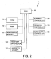
- FIG. 2 shows a schematic structure of the control system of the color copier 1. That is, the color copier 1 is composed of: a CPU 50 to control the entire apparatus; a ROM 51 storing a control program and others; a RAM 52 for staring data; a non-volatile memory 53 to once store sensed values of toner density; which will be described later; a scanner controller 54 to control the scanner unit 2; a process controller 55 to control the image forming unit 4; and a paper supply controller 56 to control the paper supply unit 6.
- the CPU 50 is connected with a toner density detector 100 to detect toner density in the yellow developing device 15Y, the magenta developing device 15M and the cyan developing device 15C, and a magnetic sensor 101 provided in the black developing device 14.
- the black developing device 14 is moved downward and separated from the drum surface 11a and the revolver type color developing device 15 is rotated clockwise and the yellow developing device 15Y is opposed to the drum surface 11a. Further, the belt cleaner 22 is rotated counterclockwise centering around the shaft 22a and separated from the intermediate transfer belt 16. The secondary transfer roller 24 is moved in the direction to separate from the vertical conveying path 26 (the right direction in FIG. 1) and separated from the intermediate transfer belt 16 (ST1).
- image data are read from a document (not shown) through the scanner 2 or image data are input from an external device (not shown) (ST2). Further, the photosensitive drum 11 is rotated clockwise and the drum surface 11a is uniformly charged to a specified potential by the main charger 12. At this time, the intermediate transfer belt 16 is also rotated counterclockwise.
- the exposure unit 13 is operated based on color separated yellow image data and a yellow electrostatic latent image is formed on the drum surface 11a.
- the exposure timing at this time is acquired by sensing a sensing mark (not shown) pasted on the inside of the intermediate transfer belt 16 by a sensor (not shown).
- the yellow developer is supplied to an electrostatic latent image formed on the drum surface 11a through the yellow developing device 15Y, the yellow electrostatic latent image is developed and formed on the drum surface 11a (ST3). Further, when a yellow toner density value sensed previously was stored in the non-volatile memory 53, the toner supply to the yellow developing device 15Y from the toner cartridge 15y is controlled based on the sensed value.
- the yellow developer image thus formed on the drum surface 11a is moved by the rotation of the photosensitive drum 11 and passes through the primary transfer region adjacent to the intermediate transfer belt 16.
- the residual yellow developer left on the drum surface 11a without transferred is removed by the drum cleaner 17. At this time, the residual charge on the drum surface 11a is also eliminated.
- the yellow developing device 15Y is opposed to the drum surface 11a and forming the yellow developer image thereon, the developer toner density of the magenta developing device 15M is detected. The detected value of this magenta toner density is once stored in the non-volatile memory 53 (ST4).
- the drum surface 11a is uniformly charged by the main charger 12. Then, the revolver type color developing device 15 is rotated and the magenta developing device 15 is opposed to the drum surface 11a and a magenta developer image is formed on the drum surface 11a. At the same time, based on a magenta toner density sensed value stored in the non-volatile memory 53, the toner supply into the magenta developing device 15M from the toner cartridge 14m is controlled (ST5).
- the toner density of the developer of the cyan developing device 15C to form a next color developer image is detected.
- This detected value of the cyan toner density is once stored in the non-volatile memory 53 (ST6).
- the revolver type color developing device 15 is rotated and the cyan developing device is opposed to the drum surface 11a and a cyan developer image is formed on the drum surface 11a.
- the toner supply into the magenta developing device 15M from the toner cartridge 15m is controlled (ST5).
- the toner density of the developer of the cyan developing device 15C to form a next color developer image is detected by the toner density detector 100.
- This cyan toner density sensed value is once stored in the non-volatile memory 53 (ST6).
- the revolver type color developing device 15 is rotated to oppose the cyan developing device 15C to the drum surface 11a, and a cyan developer image is formed on the drum surface 11a.
- the toner supply into the cyan developing device 15C from the toner cartridge 15c is controlled (ST7).
- a series of operations described above; that is, the exposure ⁇ development ⁇ transfer to the intermediate transfer belt 16 are executed and a magenta developer image is transferred over a yellow developer image on the intermediate transfer belt 16.
- the magenta developer image was transferred, the cyan developer image is transferred over the magenta developer image on the intermediate transfer belt 16.
- the revolver type color developing device 15 is rotated and the cyan developing device 15C is opposed to the drum surface, and while a cyan developer image is being formed, the developer toner density of the yellow developing device 15Y is sensed. This sensed yellow toner density value is once stored in the non-volatile memory 53 (ST8).
- the supply of a toner into the yellow developing device 15Y from the toner cartridge 15y is prepared based on the yellow toner density sensed value stored in the non-volatile memory 53.
- the revolver type color developing device 15 is rotated to a home position of each developing device 15Y, 15M and 15C not opposite to the drum surface 11a and the black developing device 14 is raised to oppose to the drum surface 11a and a black developer image is formed.
- the toner supply into the black developing device 14 from the toner cartridge 14a is controlled based on the black toner sensed value stored in the non-volatile memory 53 (ST9). Under this state, the same process as that described above is executed and a black developer image is transferred to the intermediate transfer belt 16 over the yellow, magenta and cyan developer images.
- a 2-component black developer is contained in the black developing device 14 and the toner density is sensed. This sensed value of the black toner density is also once stored in the non-volatile memory 53 (ST10). The toner supply into the black developing device 14 from the toner cartridge 14a is controlled based on this stored density value. Further, the black developing device 14 is composed separately from the rotating revolver type color developing device 15 and is so arranged as to move to a position separate from a position opposite to the drum surface by a cam (not shown).
- the paper P with the color developer images transferred in a lump passes through a fixing device 38 wherein it is heated and pressurized and the color developer images are fixed on the paper P and a color image is formed.
- the paper P with a color image thus formed is discharged on a discharged document receiving tray 44 by the discharging roller 42 provided at the downstream side of the fixing device 38 (ST12).
- the discharge tray 44 is provided inside of the housing 3.
- the 2-component developer toner density detector 100 comprising an infrared light emission element and a light receiving element to receive the infrared light reflecting from developers on the developing rollers will be explained.
- a light emitting diode (LED) of waveform 880 nm is used as an infrared light emitting element.
- emission wavelength any wavelength above 780 nm is usable. It depends upon spectral reflection coefficient of toner.
- non-magnetic toner for 2-component developer is composed of resin, wax, charge control agent, pigment, additive, etc. and yellow, magenta and cyan toners have a characteristic to reflect the light in the infrared region.
- the magnetic carrier used in this embodiment is a general carrier used in a color copier available in the market at present and is ferrite carrier thinly coated with resin. This carrier has a feature to absorb infrared light and when toner density becomes thick, a toner amount covering the carrier surface increase and therefore, the reflecting light from toner increases, accordingly.
- the black toner has a feature to absorb the light ranging from the visible light to the infrared light region and therefore, the toner density detector 100 is not able to sense its toner density. That is, the carrier surface and the toner infrared light reflection feature are almost same and it is difficult to sense toner density.
- FIG. 4 is a graph showing these results.
- Y yellow
- M magenta
- C cyan
- FIG. 4 is a graph showing these results.
- Y yellow
- M magenta
- C cyan
- the toner density detector 100 is installed at a position opposite to the developing roller.
- the toner density sensor was opposed to the developing roller at the position of the main pole (a magnet pole to form a developer image at a position opposite to the photosensitive drum 11)
- a developer is in the erected state and the toner density detector 100 is largely affected by the reflecting light from the developer roller itself and cannot be used.
- the toner density detector 100 is arranged between the developing rollers so as to oppose to the portion where the developer on the developer roller is not in the erected state.
- the place to install the toner density detector 100 is desired to be such a place where another developing device is waiting when a certain color developing device is at the position in opposite to the photosensitive drum.
- the toner density sensor is installed at a position turned by 120 degree counterclockwise from a developing device opposing to the photosensitive drum 11 almost above the developing devices and therefore, is hardly affected by toners scattering from the developing devices. It is not impossible to look a developer on a developing roller of a developing device at the position opposite to the photosensitive drum 11 but the apparatus becomes a large size and may have a large defect as a product.
- the revolver type color developing device 15 when the revolver type color developing device 15 is rotated by at least one turn, it becomes possible to sense all developer toner density in the revolver type color developing device 15.
- the toner density can be sensed in the single sheet printing or the continuous printing without interrupting the print job and undesirably wasting toners by forming a toner density sensing patch between sheets of paper.
- the toner density detector 100 is installed at a place where another developing device is waiting when a certain color developing device is at a position opposite to the photosensitive drum 11 even if a sensor or a carrier capable of sensing a black toner density was developed by a technology in the future. Therefore, in the continuous black printing job, the toner density of black developer cannot be sensed by the toner density detector 100.
- the continuous printing job in order to sense the toner density, the continuous printing job must be interrupted and the density of black developer toner must be sensed by rotating the revolver type color developing device 15 with the toner density detector 100 or the black toner density must be sensed according to adhered toner amount using another density sensor by forming a black developer image patch.
- the printing speed performance drop, undesirable toner waste and a large defect will result.
- a black developing device that is used exclusively in the color image forming into the revolver type color developing device 15.
- the single black color printing developing device must be absolutely a secondary developing device. This is for sensing toner density without problems in single sheet printing as well as continuous printing of colors and black images.
- the incorporation of a 4 color first developing devices of yellow, magenta, cyan and black into the revolver type color developing devices and arrangement of a second developing device for exclusive use for black printing are also included in the present invention.
- the rotating operation of the revolver type color developing device is associated in the color image forming and therefore, toner density of developers of all developing devices can be sensed and regardless of the continuous print or a single sheet printing, toner density of developers can be sensed without forming a patch for toner density sensing on the developing rollers. Accordingly, it is possible to form images without lowering the continuous print speed performance and undesirably wasting toners by forming patches.
- the black developing device 14 is moved downward and separated from the drum surface 11a and the developing devices (15Y, 15M and 15C) of the revolver type color developing device are at the positions not opposing to the drum surface 11a. Further, the belt cleaner 22 is energized in the direction to rotate the shaft 22a clockwise and is in contact with the intermediate transfer belt 16, and the secondary transferring roller 24 is moved in the direction (the rightward in FIG. 1) to get away from the vertical direction conveying path 26 and is at the position away from the intermediate transfer belt 16.
- image data are read from a document (not shown) by the scanner unit 2 or image data are input from an external device (not shown). Further, the photosensitive drum 11 is rotated clockwise and the drum surface 11a is uniformly charged to a specified potential by the main charger 12. At this time, the intermediate transfer belt 16 is also rotated counterclockwise.
- the exposure unit 13 is operated based on the black image data and a black electrostatic latent image is formed on the drum surface 11a.
- the exposing timing at this time is not required to comply with a sensing mark (not shown) pasted inside the intermediate transfer belt 16 but the exposure is started by another signal.
- the black developing device 14 is opposed to the drum surface 11a, a black developer is supplied to an electrostatic latent image, the black electrostatic latent image is developed and the black developer image is formed on the drum surface 11a.
- the black developer image thus formed on the drum surface 11a is moved with the rotation of the photosensitive drum 11 and passes through the primary transfer region contacting the intermediate transfer belt 16.
- the black developer image is conveyed to the secondary transfer region and contacted to the intermediate transfer belt 16. Then, the black developer image is transferred on a paper P likewise the color image forming, fixed in the fixing device 38 and discharged on the discharged document receiving tray 44.
- the revolver type color developing device 15 is not rotated and therefore, in both the single sheet and continuous sheet printing, the black image printing can be made in the same manner as described above likewise an ordinary exclusive black image forming apparatus.
- toner density control 2-component developer for black printing is contained in the black developing device 14 as explained in the color image forming and toner density is sensed by the magnetic sensor 101 in order to sense this toner density.
- the sensed toner density is once stored in the non-volatile memory 53 and based on this sensed toner density value, toner supply to the black developing device 14 from the toner cartridge 14a is controlled.
- the toner supply can be made during the same single printing job or based on the sensed value stored in the previous printing job.
- This toner density sensing and toner supply operation can be made in the single sheet printing and the continuous printing without problems and the stable toner density can be controlled. Further, it is not required to make the undesirable patch printing for the toner density sensing and the continuous printing speed performance is not lowered and toner is not wasted undesirably.
- the black developing device 14 is provided separately from the revolver type color developing device 15 containing other color developing devices.
- the amount of black developer contained in the black developing device and the toner cartridge can be made large differing from other color developing units and as a result, the number of maintenance such as Exchange of developers, toner supply, etc. can be reduced largely.
- the image forming apparatus of the present invention uses 2-component developer and is capable of preventing defective images resulting from adherence of developer, and reducing the number of maintenance without lowering continuous printing speed performance and undesirable wasting of toner by patch forming.
- the toner density detector 100 is composed of an infrared light emitting element and a receiving element to receive infrared light reflecting from developers and the sensing position can be any position not opposing to the developing roller.
- a transparent window may be provided at a part of a developing unit to sense toner density of developer inside the unit through the window.
Landscapes
- Physics & Mathematics (AREA)
- General Physics & Mathematics (AREA)
- Color Electrophotography (AREA)
- Dry Development In Electrophotography (AREA)
Abstract
Description
- This application is based upon and claims the benefit of priority from the prior Japanese Patent Application No. 2003-411811, filed on December 10, 2003; the entire contents of which are incorporated herein by reference.
- The present invention relates to an image forming apparatus such as a color printer, a color copier, etc. to form color images on sheets of paper and a toner supply method.
- A color laser printer is known as an image forming apparatus to form a color image on a sheet of paper as disclosed in the Japanese Patent Application Publication No. 11-84801.
- This color laser printer has an image carrier on which latent images are formed by the exposure, plural developing devices to develop this latent images by supply specified color developers, a intermediate transfer belt to transfer color developer images formed on the image carrier by overlapping each other, a transferring device to transfer the color developer images transferred by superposing each other on the intermediate transfer belt, and a transfer unit to transfer color developer images formed on a intermediate transfer belt en block on paper, and a cassette housing a number of sheets of paper.
- A yellow, magenta and cyan developing devices are set in a developing device rotary arranged rotatably at the side of the image carrier, and a black developing device is a separate unit from the developing device rotary and arranged opposite to the rotary from above the image carrier. The developing device rotary houses 3 developing devices side by side in its peripheral direction and opposes a specific color developing device to the image carrier by rotating.
- The intermediate transfer belt is brought to contact the image carrier from below.
- An image receiving medium (paper) taken out of the cassette is conveyed on a conveying path extending nearly in the horizontal direction under the intermediate transfer belt and passes the intermediate transfer belt. At this time, color developer images transferred on the intermediate transfer belt in the overlapped state are transferred on the image receiving medium (paper) in a lump.
- However, a conventional printer in the structure as described above has such problems as shown below.
- First, as a black developing device is arranged above the image carrier, a developer undesirably scattering from this developing device drops on the image carrier. When a developer falls on the image carrier, this developer is transferred on a sheet by way of a intermediate transfer belt and an image becomes worse (dirty).
- Second, because a paper is conveyed on the conveying path under the intermediate transfer belt, color developers undesirably scattered from respective color developing devices set in the developing device rotary and a black developer scattered from the black developing device fall on the paper conveyed on the conveying path. Thus, when developers fall on a paper, an image becomes defective.
- The developing devices disclosed here use single-component developers, respectively and it is not necessary to check toner density of a developer in respective developing device.
- In general, 2-component developing system has merits in the image quality such as wider expression of gradation and in particular, excellent reproduction of bright halftone. Further, regarding a toner charging amount, a 2-component developing system is higher than a single-component developer and scattering of toners around characters, very small dots and thin lines is less than a single-component developing system. Furthermore, consumables of 2-component developing system are usable for longer than a single-component developing system; for example, developing devices can be used up to the service life of the main body and a running cost per sheet of paper is cheaper than that of a single-component developing system. In recent years, many image forming apparatus in the 2-component developing system are provided in the market.
- An example of the 2-component developing system image forming apparatus is disclosed in, for example, the Japanese Patent Application Publication No. 9-218589.
- The image forming apparatus in this example has black, cyan, magenta and yellow developing devices. These devices are in the rotatable structure and supported by the main body. Each of the color developing devices is movable to a position to visualize a latent image formed on the photosensitive drum according to need. Developers retained in these developing devices are two-compoent developer and it is necessary to detect density of each toner and control to supply to maintain toners always at specified densities.
- In this example, the image forming apparatus has the black, cyan, magenta and yellow developing portions, which are supported rotatably by the main body and therefore, it is difficult to use magnetic sensors that are normally used for detecting toner density of two-compoent developer. This is because it is difficult to install a means to transmit an output signal from a sensor to the main body.
- For this reason, in this example, a density sensor is arranged at the downstream side in the peripheral direction of the photosensitive drum of the developing device to detect density of an image developed on the photosensitive drum. The supply of a toner to the developing device, change of developing conditions, etc. are executed according to the density signal from the density sensor, and the toner density of 2-component developer is controlled to maintain always at a specified toner density.
- However, in order to detect a toner density according to this toner density supply and control method, it is necessary to form a patch for the density detection by interrupting a print job for every specified number of sheets during the continuous printing. Further, it is also necessary to form a patch for density according to a timing between a sheet and a sheet conveyed. In this case, there were such defects that the printing speed was dropped and toners were consumed undesirably.
- An object of the present invention is to provide an image forming apparatus using a two-component developer and a toner supply and control method to prevent defective images generated by adhesion of developers without lowering the print speed performance for detecting toner density and undesirably consuming toner.
- According to embodiments of the present invention, an image forming apparatus is provided, which comprises an image carrier on which plural latent images are formed repeatedly; a color developing device which has plural first developing units containing specified color developers arranged side by side in a rotating direction and are able to rotate the plural first developing units to oppose to the image carrier selectively and develop the latent images by supplying specified color developers; a second developing device arranged along the outer surface of the image carrier at a position differing from the position where the first developing units of the color developing device is opposed to the image carrier, and opposes to the image carrier and develops the latent image by supplying a specified color developer; a first toner density detecting measns for detecting a toner density of the developers contained in the first developing units, wherein the developers are two-compoent developer comprising at least non-magnetic toner and magnetic carrier; and a second toner density detecting means for detecting the toner densitiy of the developers contained in the second developing device of which detecting method differs from the first toner density detecting means, wherein the developer is a two-component developer comprising at least non-magnetic toner and magnetic carrier.
- Further, according to embodiments of the present invention, there is provided a toner supply method of an image forming apparatus which has an image carrier on which plural latent images are formed repeatedly, plural first developing units containing specified color developers arranged in the rotating direction, color developing units provided to arrange the plural first developing units selectively to oppose to the image carrier and develop the latent images by specific color developers, and a second developing unit arranged at a position opposing to the image carrier at a position differing from the position the first developing units of the color developing device are opposed to the image carrier and supply a specific color developer to develop the latent images, the method comprising: detecting toner density of two-component developer contained in the first developing units arranged opposing to next to the applicable first developing unit when the color developing device is rotated and the first developing unit is opposed to the image carrier; storing the toner density detected value of the first developing units; and controlling the toner supply to the applicable first developing units based on the stored toner density detected value of the first developing unit when-the color developing device is rotated and the next first developing unit is arranged to oppose to the image carrier.
-
- FIG. 1 is a cross-sectional view schematically showing the internal structure of a color copier involved in the embodiment of the present invention;
- FIG. 2 is a block diagram schematically showing the structure of the control system of the color copier shown in FIG. 1;
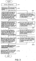
- FIG. 3 is a flowchart for explaining the color image forming operation of the color copier shown in FIG. 1; and
- FIG. 4 is a graph for explaining the infrared light reflection coefficient characteristic of each color toner.
-
- The embodiment of the present invention will be explained below in detail referring to the attached drawings.
- FIG. 1 schematically shows the inner internal structure of a
color copier 1 as an image forming apparatus involved in the embodiment of the present invention. - The
color copier 1 has ascanner unit 2, animage forming unit 4, and apaper supply unit 6. Thescanner unit 2 illuminates an original set on a document table (not shown), leads the reflecting light from the original to a light receiving element through plural optical members, and outputs image data by the photoelectric transfer. Theimage forming unit 4 outputs an image based on image data region from the original by thescanner unit 2 or input from an external device (not shown) on a paper P (an image receiving medium). Thepaper supply unit 6 supplied a paper P to theimage forming unit 4. - The
color copier 1 has ahousing 3 containing the above-mentioned units. On the right side surface of thehousing 3, apaper reversing unit 8 and a manualpaper supply unit 9 are installed detachably. Thepaper reversing unit 8 reverses a paper P with an image formed on which one side and supplies to theimage forming unit 4 again. The manualpaper supply unit 9 supplies a paper manually to theimage forming unit 4. - The
image forming unit 4 includes a photosensitive drum 11 (an image carrier) which has a rotary shaft extending in the front and rear direction (a paper direction) of thecolor copier 1. Around thephotosensitive drum 11, amain charger 12, anexposure unit 13, a black developing device 14 (the second developing device), a revolver type color developing device 15 (a developing unit), an intermediate transfer belt 16 (an intermediate transfer means), and a drum cleaner 17 (a cleaning device) are provided along the rotating direction (the arrow direction in FIG. 1) of thephotosensitive drum 11. Thephotosensitive drum 11 is needed in a diameter at least 50 mm so that the above-mentioned plural devices can be arranged around it. - The
main charger 12 charges the outer surface 11a of the photosensitive drum 11 (hereinafter, referred to a drum surface 11a) to a specified potential. Theexposure unit 13 is arranged near to the lower edge of theimage forming unit 4 and forms an electrostatic latent image based on image data by exposing the drum surface 11a charged to a specified potential. When forming a color image, theexposure unit 13 forms electrostatic latent images in respective colors by exposing the drum surface 11a based on color separated image data. - The black developing
device 14 is arranged between thephotosensitive drum 11 and theexposure unit 13 to oppose to thephotosensitive drum 11 from almost in the gravity direction. The black developingdevice 14 supplies a black developer to an electrostatic latent image formed on the drum surface 11a by theexposure unit 13 to develop and form a black developer image on the drum surface 11a. The black developingdevice 14 has a mixer to stir and supply a developer and a developing roller arranged to oppose to the drum surface 11a through a specified developing gap. Further, the black developingdevice 14 is provided movably to detach the developing roller to the drum surface 11a. Further, the black developingdevice 14 is supplied with a developer from atoner cartridge 14a. - The black developing
device 14 is provided with amagnetic sensor 101. - The developer type
color developing device 15 is provided adjacent to thephotosensitive drum 11 nearly at the left side in FIG. 1. The developer typecolor developing device 15 has a yellow developingdevice 15Y (a first developing device), amagenta developing device 15M (a first developing device), and a cyan developing device 15C (a first developing device) which are basically in the almost same structure as the black developingdevice 14. These developing devices (15Y, 15 and 15C) are housed in the revolver typecolor developing device 15 detachably side by side in its rotating direction. Each of the developing devices has atoner cartridge - Further, a
toner density detector 100 to sense toner density in each developing device (15Y, 15M and 15C) is provided near the revolver typecolor developing device 15. Thetoner density detector 100 is provided at a position opposite to a developing roller (15YR, 15MR and 15CR) of applicable developing unit where a developing device (15Y, 15M and 15C to form a developer image in next color of the revolver typecolor developing device 15 is waiting. Thetoner density detector 100 is a sensor to sense toner density of 2-component developer comprising an infrared light emitting element and a light receiving element to receive the infrared light reflecting from a developer on a developing roller (15YR, 15MR and 15CR). - The developing units in
respective colors photosensitive drum 11 by rotating the revolver type developing device clockwise. - The black developing
device 14 is provided separately from the revolver typecolor developing device 15 because its using frequency is higher than other color developing devices. As a result, it becomes possible to make the black developing device and the volume of developer in a toner cartridge larger and the number of maintenance such as exchange of developer, toner supply, etc. can be reduced. - Further, the black developing
device 14 and the revolver typecolor developing device 15 in this embodiment are provided at positions outside the upper region in the gravity direction from thephotosensitive drum 11 and therefore, it is able to prevent the undesirable scattering of developers from the developingdevices photosensitive drum 11. - The
intermediate transfer belt 16 is arranged at a position where it contacts thephotosensitive drum 11 from almost above in the gravity direction. Theintermediate transfer belt 16 is stretched around a driving roller 16a, apre-transferring roller 16b, a transferring roller 16c, and atension roller 16d each of which has a rotary shaft extending in the front/rear direction. The driving roller 16a is provided statically to thehousing 3 above the revolver type color developing device. Thepre-transferring roller 16b is provided statically to thehousing 3 above thephotosensitive drum 11. The transferring roller 16c is provided statically at a position to contact the vertical transfer path that will be described later. Thetension roller 16d is energized to the outside from the inside of theintermediate transfer belt 16 to give a specified tensile force to theintermediate transfer belt 16. - In addition, a
primary transferring roller 21 is provided in the inside of theintermediate transfer belt 16 to bring theintermediate transfer belt 16 to contact the drum surface 11a and transfer a developer image formed on the drum surface 11a to theintermediate transfer belt 16. Theprimary transfer roller 21 is energized in the direction of thephotosensitive drum 11 so as to press theintermediate transfer belt 16 to the drum surface 11a at a specified pressure. - Further, the
intermediate transfer belt 16 is set in a length nearly integral multiple of the outer circumferential length of thephotosensitive drum 11. In other words, theintermediate transfer belt 16 is set in a length so that the same portion of the drum surface 11a always contacts the same position. Theintermediate transfer belt 16 is needed at least in a length more than the length of the longest paper P (431.8 mm) and thephotosensitive drum 11 is also needed in a diameter more than at least 50 mm. Therefore, in this embodiment, theintermediate transfer belt 16 is set in the minimum required length at 3 times of the outer circumferential length of thephotosensitive drum 11. - Around the
intermediate transfer belt 16, a belt cleaner 22 (a cleaning device) and a secondary transfer roller 24 (a transfer device) are provided in the state able to contact/separate to/from the belt surface. Thebelt cleaner 22 is provided on the outer surface of the driving roller 16a through theintermediate transfer belt 16 above the revolver typecolor developing device 15. In other words, thebelt cleaner 22 is provided at a position outside the above region in the gravity direction from thephotosensitive drum 11. Thesecond transfer roller 24 is provided at a position clamping the vertical conveyingpath 26 which is described later between the transfer roller 16c through theintermediate transfer belt 16. - The
drum cleaner 17 is arranged in contact with thephotosensitive drum 11 from the right side in FIG. 1. In other words, thedrum cleaner 17 is provided at a position outside the region above thephotosensitive drum 11. - That is, in this embodiment, the black developing
device 14, the revolver typecolor developing device 15, thedrum cleaner 17, and thebelt cleaner 22 are provided at positions outside the region above thephotosensitive drum 11. Further, in this embodiment, theintermediate transfer belt 16 is arranged above thephotosensitive drum 11. Therefore, according to this embodiment, developers undesirably scattered or leaked from the black developingdevice 14, the revolver typecolor developing device 15, thedrum cleaner 17, and thebelt cleaner 22 do not fall on the drum surface 11a and theintermediate transfer belt 16 and therefore, defective images resulting from adherence of developers can be prevented. - The
paper supply unit 6 has twopaper supply cassettes paper supply cassettes roller 31 is provided to take out the top paper P housed in the cassettes, respectively. At the position adjacent to the downstream side in the paper take-out direction by the pick-uproller 31, a forwardingroller 32 and aseparation roller 33 region kept in contact with each other. - Further, at the positions adjacent to the right side of the
paper supply cassettes direction conveying path 26 extending almost in the vertical upper direction passing through the secondary transfer region in contact with the above-mentionedintermediate transfer belt 16 and thesecond transfer roller 24 is provided. On the vertical conveyingpath 26, a conveyingroller pair 34 which rotates by holding a paper P, an aligning sensor to sense the arrival of a paper P, and a aligningroller pair 36 to supply a paper P to the secondary transferring region at a specified paper supply timing region arranged toward the second transferring region from the lower part. - On the vertical conveying
path 26 extending upward by passing the secondary transferring region, a fixingdevice 38 is provided to fix a developer image transferred on a paper P by heating and pressing. The fixingdevice 38 has aheat roller 38b having a built-in heater and apressure roller 38a arranged to theheat roller 38b by pressing. - That is, in this embodiment, the vertical conveying
path 26 is extended by passing the position separated from the revolver typecolor developing device 15, that is, to the right side of thephotosensitive drum 11 in FIG. 1. In other words, the vertical conveyingpath 26 is extended by passing a position outside the lower region in the gravity direction from the black developingdevice 14, the revolver typecolor developing device 15, and thebelt cleaner 22. Thus, the adhesion of developers undesirably scattering from the black developingdevice 14 and the developingdevices color developing device 15 to paper P conveyed through the secondary transferring region can be prevented. Accordingly, it is also possible to prevent that developers leaked undesirably from thedrum cleaner 17 and thebelt cleaner 22 falls on paper P. - Further, as the above-mentioned vertical conveying
path 26 was adopted, the entire structure of thecolor copier 1 could be downsized and it becomes easy to make the paper jam processing. That is, the size of the entire apparatus could be made small as the devices in the vertical direction were made small by arranging the relatively large revolver typecolor developing device 15 at the left side of thephotosensitive drum 11 as shown in FIG. 1 and the paper P conveying path was made short by adopting the vertical conveyingpath 26. Further, the vertical conveyingpath 26 in the vicinity of the secondary transferring region could be exposed easily to the outside of thehousing 3 by opening thepaper reversing unit 8 and asecondary transferring unit 60. As a result, even when the paper jam is caused in the vicinity of the secondary transferring region, the jam processing can be made easily. - FIG. 2 shows a schematic structure of the control system of the
color copier 1. That is, thecolor copier 1 is composed of: aCPU 50 to control the entire apparatus; aROM 51 storing a control program and others; aRAM 52 for staring data; anon-volatile memory 53 to once store sensed values of toner density; which will be described later; ascanner controller 54 to control thescanner unit 2; aprocess controller 55 to control theimage forming unit 4; and apaper supply controller 56 to control thepaper supply unit 6. - Further, the
CPU 50 is connected with atoner density detector 100 to detect toner density in the yellow developingdevice 15Y, themagenta developing device 15M and the cyan developing device 15C, and amagnetic sensor 101 provided in the black developingdevice 14. - Next, the color image forming operation of the
color copier 1 in this structure will be explained referring to the flowchart shown in FIG. 3. Further, the operations described below are controlled by theCPU 50. - As the initial operation, the black developing
device 14 is moved downward and separated from the drum surface 11a and the revolver typecolor developing device 15 is rotated clockwise and the yellow developingdevice 15Y is opposed to the drum surface 11a. Further, thebelt cleaner 22 is rotated counterclockwise centering around theshaft 22a and separated from theintermediate transfer belt 16. Thesecondary transfer roller 24 is moved in the direction to separate from the vertical conveying path 26 (the right direction in FIG. 1) and separated from the intermediate transfer belt 16 (ST1). - Then, image data are read from a document (not shown) through the
scanner 2 or image data are input from an external device (not shown) (ST2). Further, thephotosensitive drum 11 is rotated clockwise and the drum surface 11a is uniformly charged to a specified potential by themain charger 12. At this time, theintermediate transfer belt 16 is also rotated counterclockwise. - Further, the
exposure unit 13 is operated based on color separated yellow image data and a yellow electrostatic latent image is formed on the drum surface 11a. The exposure timing at this time is acquired by sensing a sensing mark (not shown) pasted on the inside of theintermediate transfer belt 16 by a sensor (not shown). - In succession, the yellow developer is supplied to an electrostatic latent image formed on the drum surface 11a through the yellow developing
device 15Y, the yellow electrostatic latent image is developed and formed on the drum surface 11a (ST3). Further, when a yellow toner density value sensed previously was stored in thenon-volatile memory 53, the toner supply to the yellow developingdevice 15Y from thetoner cartridge 15y is controlled based on the sensed value. - The yellow developer image thus formed on the drum surface 11a is moved by the rotation of the
photosensitive drum 11 and passes through the primary transfer region adjacent to theintermediate transfer belt 16. - At this time, bias of reverse polarity to the potential of the yellow developer image is given to the yellow developer image formed on the drum surface 11a by the
primary transfer roller 21 and the yellow developer image is transferred on theintermediate transfer belt 16. As theintermediate transfer belt 16 is set in the length integral multiple of that of the outer circumference of thephotosensitive drum 11, the developer image is transferred to the same position on theintermediate transfer belt 16 from the drum surface 11a. - After the yellow developer image was transferred on the
intermediate transfer belt 16, the residual yellow developer left on the drum surface 11a without transferred is removed by thedrum cleaner 17. At this time, the residual charge on the drum surface 11a is also eliminated. While the yellow developingdevice 15Y is opposed to the drum surface 11a and forming the yellow developer image thereon, the developer toner density of the magenta developingdevice 15M is detected. The detected value of this magenta toner density is once stored in the non-volatile memory 53 (ST4). - Then, as the preparation to form a next magenta electrostatic latent image on the drum surface 11a, the drum surface 11a is uniformly charged by the
main charger 12. Then, the revolver typecolor developing device 15 is rotated and themagenta developing device 15 is opposed to the drum surface 11a and a magenta developer image is formed on the drum surface 11a. At the same time, based on a magenta toner density sensed value stored in thenon-volatile memory 53, the toner supply into themagenta developing device 15M from the toner cartridge 14m is controlled (ST5). - Further, at the same time, the toner density of the developer of the cyan developing device 15C to form a next color developer image is detected. This detected value of the cyan toner density is once stored in the non-volatile memory 53 (ST6).
- In succession, the revolver type
color developing device 15 is rotated and the cyan developing device is opposed to the drum surface 11a and a cyan developer image is formed on the drum surface 11a. At the same time, based on a magenta toner density sensed value stored in thenon-volatile memory 53, the toner supply into themagenta developing device 15M from thetoner cartridge 15m is controlled (ST5). - Further, at the same time, the toner density of the developer of the cyan developing device 15C to form a next color developer image is detected by the
toner density detector 100. This cyan toner density sensed value is once stored in the non-volatile memory 53 (ST6). - In succession, the revolver type
color developing device 15 is rotated to oppose the cyan developing device 15C to the drum surface 11a, and a cyan developer image is formed on the drum surface 11a. At the same time, based on a magenta toner density sensed value stored in thenon-volatile memory 53, the toner supply into the cyan developing device 15C from thetoner cartridge 15c is controlled (ST7). - A series of operations described above; that is, the exposure→ development→transfer to the
intermediate transfer belt 16 are executed and a magenta developer image is transferred over a yellow developer image on theintermediate transfer belt 16. Thus, after the magenta developer image was transferred, the cyan developer image is transferred over the magenta developer image on theintermediate transfer belt 16. - In succession, the revolver type
color developing device 15 is rotated and the cyan developing device 15C is opposed to the drum surface, and while a cyan developer image is being formed, the developer toner density of the yellow developingdevice 15Y is sensed. This sensed yellow toner density value is once stored in the non-volatile memory 53 (ST8). - At the next time, when the yellow developing
device 15Y is rotated and moved to the position opposite to the drum surface 11a in the print operation, the supply of a toner into the yellow developingdevice 15Y from thetoner cartridge 15y is prepared based on the yellow toner density sensed value stored in thenon-volatile memory 53. - Then, the revolver type
color developing device 15 is rotated to a home position of each developingdevice device 14 is raised to oppose to the drum surface 11a and a black developer image is formed. At the same time, the toner supply into the black developingdevice 14 from thetoner cartridge 14a is controlled based on the black toner sensed value stored in the non-volatile memory 53 (ST9). Under this state, the same process as that described above is executed and a black developer image is transferred to theintermediate transfer belt 16 over the yellow, magenta and cyan developer images. - Further, a 2-component black developer is contained in the black developing
device 14 and the toner density is sensed. This sensed value of the black toner density is also once stored in the non-volatile memory 53 (ST10).
The toner supply into the black developingdevice 14 from thetoner cartridge 14a is controlled based on this stored density value. Further, the black developingdevice 14 is composed separately from the rotating revolver typecolor developing device 15 and is so arranged as to move to a position separate from a position opposite to the drum surface by a cam (not shown). - Thus, when all color developer images are superposed each other on the
intermediate transfer belt 16, thesecondary transfer roller 24 is moved leftward in FIG. 1 and comes in contacted with theintermediate transfer belt 16. Under this state, all color developer images superposed on theintermediate transfer belt 16 are moved with the rotation of theintermediate transfer belt 16 and passes the secondary transfer region between thebelt 16 and thesecondary transfer roller 24. Thereafter, when the top portion of the secondary transfer completed region comes to the belt cleaner position, thebelt cleaner 22 also comes in contact with theintermediate transfer belt 16. - At this time, papers P taken out from the
cassettes path 26 by the conveyingroller pair 34 and after aligned once by the aligningroller pair 36, conveyed into the secondary transfer region at a specified timing. - Then, a bias in reverse polar to the potential of the color developer images is applied by the
secondary transfer roller 24 and the color developer images on theintermediate transfer belt 16 are transferred on papers P (ST11). After the developer images are transferred on a paper P, developers remained on theintermediate transfer belt 16 are removed by thebelt cleaner 22. - Thereafter, the paper P with the color developer images transferred in a lump passes through a fixing
device 38 wherein it is heated and pressurized and the color developer images are fixed on the paper P and a color image is formed. The paper P with a color image thus formed is discharged on a dischargeddocument receiving tray 44 by the dischargingroller 42 provided at the downstream side of the fixing device 38 (ST12). In this embodiment, thedischarge tray 44 is provided inside of thehousing 3. - Next, the 2-component developer
toner density detector 100 comprising an infrared light emission element and a light receiving element to receive the infrared light reflecting from developers on the developing rollers will be explained. - In this embodiment, a light emitting diode (LED) of waveform 880 nm is used as an infrared light emitting element. Regarding emission wavelength, any wavelength above 780 nm is usable. It depends upon spectral reflection coefficient of toner.
- In general, non-magnetic toner for 2-component developer is composed of resin, wax, charge control agent, pigment, additive, etc. and yellow, magenta and cyan toners have a characteristic to reflect the light in the infrared region. The magnetic carrier used in this embodiment is a general carrier used in a color copier available in the market at present and is ferrite carrier thinly coated with resin. This carrier has a feature to absorb infrared light and when toner density becomes thick, a toner amount covering the carrier surface increase and therefore, the reflecting light from toner increases, accordingly.
- The black toner has a feature to absorb the light ranging from the visible light to the infrared light region and therefore, the
toner density detector 100 is not able to sense its toner density. That is, the carrier surface and the toner infrared light reflection feature are almost same and it is difficult to sense toner density. - FIG. 4 is a graph showing these results. Regarding the yellow (Y), magenta (M) and cyan (C) toners, largely inclined linear outputs are obtained for toner density. However, as to the black toner, the output is flat and not usable for the sensing of toner density (the sensing was not attained by the present technology but there is the possibility for developing a sensor and/or carrier capable of sensing black toner density in the future).
- It is described above that the
toner density detector 100 is installed at a position opposite to the developing roller. When explaining more in detail, if the toner density sensor was opposed to the developing roller at the position of the main pole (a magnet pole to form a developer image at a position opposite to the photosensitive drum 11), a developer is in the erected state and thetoner density detector 100 is largely affected by the reflecting light from the developer roller itself and cannot be used. - So, in this embodiment, the
toner density detector 100 is arranged between the developing rollers so as to oppose to the portion where the developer on the developer roller is not in the erected state. - The place to install the
toner density detector 100 is desired to be such a place where another developing device is waiting when a certain color developing device is at the position in opposite to the photosensitive drum. In this embodiment, the toner density sensor is installed at a position turned by 120 degree counterclockwise from a developing device opposing to thephotosensitive drum 11 almost above the developing devices and therefore, is hardly affected by toners scattering from the developing devices. It is not impossible to look a developer on a developing roller of a developing device at the position opposite to thephotosensitive drum 11 but the apparatus becomes a large size and may have a large defect as a product. - Accordingly, when the revolver type
color developing device 15 is rotated by at least one turn, it becomes possible to sense all developer toner density in the revolver typecolor developing device 15. In the color image forming, the toner density can be sensed in the single sheet printing or the continuous printing without interrupting the print job and undesirably wasting toners by forming a toner density sensing patch between sheets of paper. - Further, when the black developing device containing black developer is housed in the revolving type color developing device, the
toner density detector 100 is installed at a place where another developing device is waiting when a certain color developing device is at a position opposite to thephotosensitive drum 11 even if a sensor or a carrier capable of sensing a black toner density was developed by a technology in the future. Therefore, in the continuous black printing job, the toner density of black developer cannot be sensed by thetoner density detector 100. So, in order to sense the toner density, the continuous printing job must be interrupted and the density of black developer toner must be sensed by rotating the revolver typecolor developing device 15 with thetoner density detector 100 or the black toner density must be sensed according to adhered toner amount using another density sensor by forming a black developer image patch. - In any case, the printing speed performance drop, undesirable toner waste and a large defect will result. However, it is possible to incorporate a black developing device that is used exclusively in the color image forming into the revolver type
color developing device 15. In this case, the single black color printing developing device must be absolutely a secondary developing device. This is for sensing toner density without problems in single sheet printing as well as continuous printing of colors and black images. The incorporation of a 4 color first developing devices of yellow, magenta, cyan and black into the revolver type color developing devices and arrangement of a second developing device for exclusive use for black printing are also included in the present invention. - The rotating operation of the revolver type color developing device is associated in the color image forming and therefore, toner density of developers of all developing devices can be sensed and regardless of the continuous print or a single sheet printing, toner density of developers can be sensed without forming a patch for toner density sensing on the developing rollers. Accordingly, it is possible to form images without lowering the continuous print speed performance and undesirably wasting toners by forming patches.
- Next, the black image forming operation by the
color copier 1 will be explained. - As the initial state, the black developing
device 14 is moved downward and separated from the drum surface 11a and the developing devices (15Y, 15M and 15C) of the revolver type color developing device are at the positions not opposing to the drum surface 11a. Further, thebelt cleaner 22 is energized in the direction to rotate theshaft 22a clockwise and is in contact with theintermediate transfer belt 16, and thesecondary transferring roller 24 is moved in the direction (the rightward in FIG. 1) to get away from the verticaldirection conveying path 26 and is at the position away from theintermediate transfer belt 16. - Then, image data are read from a document (not shown) by the
scanner unit 2 or image data are input from an external device (not shown). Further, thephotosensitive drum 11 is rotated clockwise and the drum surface 11a is uniformly charged to a specified potential by themain charger 12. At this time, theintermediate transfer belt 16 is also rotated counterclockwise. - Further, the
exposure unit 13 is operated based on the black image data and a black electrostatic latent image is formed on the drum surface 11a. The exposing timing at this time is not required to comply with a sensing mark (not shown) pasted inside theintermediate transfer belt 16 but the exposure is started by another signal. - This is because it is not necessary to superpose colors on the
intermediate transfer belt 16 and also, a first print time can be made short. - In succession, the black developing
device 14 is opposed to the drum surface 11a, a black developer is supplied to an electrostatic latent image, the black electrostatic latent image is developed and the black developer image is formed on the drum surface 11a. The black developer image thus formed on the drum surface 11a is moved with the rotation of thephotosensitive drum 11 and passes through the primary transfer region contacting theintermediate transfer belt 16. - At this time, bias of polarity reverse to the potential of the black developer image is given through the primary transferring roller and the black developer image on the drum surface 11a is transferred on the
intermediate transfer belt 16. - Thereafter, the black developer image is conveyed to the secondary transfer region and contacted to the
intermediate transfer belt 16. Then, the black developer image is transferred on a paper P likewise the color image forming, fixed in the fixingdevice 38 and discharged on the dischargeddocument receiving tray 44. - In case of the black printing, the revolver type
color developing device 15 is not rotated and therefore, in both the single sheet and continuous sheet printing, the black image printing can be made in the same manner as described above likewise an ordinary exclusive black image forming apparatus. - As to the toner density control, 2-component developer for black printing is contained in the black developing
device 14 as explained in the color image forming and toner density is sensed by themagnetic sensor 101 in order to sense this toner density. The sensed toner density is once stored in thenon-volatile memory 53 and based on this sensed toner density value, toner supply to the black developingdevice 14 from thetoner cartridge 14a is controlled. - The toner supply can be made during the same single printing job or based on the sensed value stored in the previous printing job.
- This toner density sensing and toner supply operation can be made in the single sheet printing and the continuous printing without problems and the stable toner density can be controlled. Further, it is not required to make the undesirable patch printing for the toner density sensing and the continuous printing speed performance is not lowered and toner is not wasted undesirably.
- As described above, the black developing
device 14 is provided separately from the revolver typecolor developing device 15 containing other color developing devices. Thus, the amount of black developer contained in the black developing device and the toner cartridge can be made large differing from other color developing units and as a result, the number of maintenance such as Exchange of developers, toner supply, etc. can be reduced largely. - The image forming apparatus of the present invention uses 2-component developer and is capable of preventing defective images resulting from adherence of developer, and reducing the number of maintenance without lowering continuous printing speed performance and undesirable wasting of toner by patch forming.
- Further, the present invention is not limited to the embodiment described above but modified variously within the scope thereof.
- For example, the
toner density detector 100 is composed of an infrared light emitting element and a receiving element to receive infrared light reflecting from developers and the sensing position can be any position not opposing to the developing roller. A transparent window may be provided at a part of a developing unit to sense toner density of developer inside the unit through the window. - Further, needless to say, various publicly known 2-component color developer toner density sensor are usable.
- In addition, for the toner density detecting method of the black developing device, publicly known toner density sensors other than magnetic sensors are usable according to the black developing device described above.
- It is explicitly stated that all features disclosed in the description and/or the claims are intended to be disclosed separately and independently from each other for the purpose of original disclosure as well as for the purpose of restricting the claimed invention independent of the composition of the features in the embodiments and/or the claims. It is explicitly stated that all value ranges or indications of groups of entities disclose every possible intermediate value or intermediate entity for the purpose of original disclosure as well as for the purpose of restricting the claimed invention, in particular as limits of value ranges.
Claims (15)
- An image forming apparatus comprising:an image carrier (11) on which plural latent images are formed repeatedly;a color developing device (15) which has plural first developing units (15Y, 15M, 15C) containing specified color developers arranged side by side in a rotating direction and are able to rotate the plural first developing units to oppose to the image carrier selectively and develop the latent images by supplying specified color developers;a second developing device (14) arranged along the outer surface of the image carrier at a position differing from the position where the first developing units of the color developing device is opposed to the image carrier, and opposes to the image carrier and develops the latent image by supplying a specified color developer;a first toner density detecting means (100) for detecting a toner density of the developers contained in the first developing units, wherein the developers are two-component developers comprising at least non-magnetic toner and magnetic carrier; anda second toner density detecting means (101) for detecting the toner density of the developers contained in the second developing device of which detecting method differs from the first toner density detecting means, wherein the developer is a two-component developer comprising at least non-magnetic toner and magnetic carrier.
- The image forming apparatus as claimed in Claim 1 further comprising:memory means (53) for storing toner density values detected by the first and the second toner density detecting means.
- The image forming apparatus as claimed in Claim 2 further comprising:control means (50, 55) for controlling the toner supply to the applicable first developing unit based on the toner density detected value stored in the memory means when the color developing device is rotated and a next first developing unit is arranged to oppose to the image carrier.
- The image forming apparatus as claimed in Claim 2 or 3 further comprising:control means (50, 55) for controlling the toner supply to the second developing unit based on the toner density detected value stored in the memory means.
- The image forming apparatus as claimed in one of Claims 1 to 4, wherein the color developing device (15) is opposed to the image carrier (11) from about the side and the second developing unit (14) is opposed to the image carrier (11) from about the lower side.
- The image forming apparatus as claimed in one of Claims 1 to 5, wherein the first toner density detecting means (100) includes a sensor to detect amount of reflecting light of infrared light irradiated to the developer.
- The image forming apparatus as claimed in one of Claims 1 to 6, wherein the first toner density detecting means detects the developer toner density in the first developing unit at the waiting position when the plural first developing units are selectively arranged to oppose to the image carrier.
- The image forming apparatus as claimed in one of Claims 1 to 7, wherein the second toner density detecting means includes a magnetic sensor (101).
- The image forming apparatus as claimed in one of Claims 1 to 8, wherein the color of developers contained in the plural first developing units are at least yellow, magenta and cyan.
- The image forming apparatus as claimed in one of Claims 1 to 9, wherein the developer color contained in the second developing unit is black.
- The image forming apparatus as claimed in one of Claims 1 to 10, wherein the amount of developer contained in the second developing unit is much more than the amount of developers contained in the first developing units in the color developing device.
- An image forming apparatus comprising:an image carrier (11) on which plural latent images are formed repeatedly;a color developing device (15) which has plural first developing units containing specified color developers except black, respectively and arranged side by side in the rotating direction, and is able to rotate the plural first developing units to oppose to the image carrier selectively and develops the latent images by supplying specified color developers; anda detector (100) irradiates the infrared light to the developer in the developing unit which is at the waiting position when the plural developing units are selectively arranged to oppose to the image carrier and detects the amount of its reflecting light.
- The image forming apparatus as claimed in Claim 12 further comprising:a black developing device (14) arranged at a position along the image carrier opposing to it and at a position differing from the position where the developing units of the color developing device is opposing to the image carrier, supplies a black developer to the latent images and develops a black image, wherein the black developing unit is opposed to the image carrier from the lower side; anda magnetic sensor (101) to detect the density of the developer in the black developing device.
- A toner supply method of an image forming apparatus which has an image carrier (11) on which plural latent images are formed repeatedly, plural first developing units (15M, 15Y, 15C) containing specified color developers arranged in the rotating direction, color developing units provided to arrange the plural first developing units selectively to oppose to the image carrier and develop the latent images by specific color developers, and a second developing unit (14) arranged at a position opposing to the image carrier at a position differing from the position the first developing units of the color developing device are opposed to the image carrier and supply a specific color developer to develop the latent images, the method comprising:detecting toner density of two-component developer contained in the first developing units arranged opposing to next to the applicable first developing unit when the color developing device is rotated and the first developing unit is opposed to the image carrier;storing the toner density detected value of the first developing units; andcontrolling the toner supply to the applicable first developing units based on the stored toner density detected value of the first developing unit when the color developing device is rotated and the next first developing unit is arranged to oppose to the image carrier.
- The toner supply method as claimed in Claim 14 further comprising:detecting toner density of two-component developer contained in the second developing unit;storing the detected toner density value of the second developing unit; andcontrolling the toner supply to the second developing unit based on the stored detected toner density value of the second developing unit.
Applications Claiming Priority (2)
| Application Number | Priority Date | Filing Date | Title |
|---|---|---|---|
| JP2003411811A JP4392234B2 (en) | 2003-12-10 | 2003-12-10 | Image forming apparatus and toner supply method |
| JP2003411811 | 2003-12-10 |
Publications (3)
| Publication Number | Publication Date |
|---|---|
| EP1542089A2 true EP1542089A2 (en) | 2005-06-15 |
| EP1542089A3 EP1542089A3 (en) | 2007-03-14 |
| EP1542089B1 EP1542089B1 (en) | 2012-02-29 |
Family
ID=34510520
Family Applications (1)
| Application Number | Title | Priority Date | Filing Date |
|---|---|---|---|
| EP04027758A Expired - Fee Related EP1542089B1 (en) | 2003-12-10 | 2004-11-23 | Image forming apparatus and toner supply method |
Country Status (4)
| Country | Link |
|---|---|
| US (1) | US20050129418A1 (en) |
| EP (1) | EP1542089B1 (en) |
| JP (1) | JP4392234B2 (en) |
| CN (1) | CN100414449C (en) |
Cited By (1)
| Publication number | Priority date | Publication date | Assignee | Title |
|---|---|---|---|---|
| CN101178568B (en) * | 2006-11-06 | 2011-11-09 | 村田机械株式会社 | Image forming device |
Families Citing this family (9)
| Publication number | Priority date | Publication date | Assignee | Title |
|---|---|---|---|---|
| JP4635733B2 (en) * | 2005-06-23 | 2011-02-23 | 富士ゼロックス株式会社 | Image forming apparatus |
| US7389059B2 (en) * | 2005-06-27 | 2008-06-17 | Fuji Xerox Co., Ltd. | Image forming apparatus having a toner concentration sensor |
| CN101206431B (en) * | 2006-12-21 | 2011-11-02 | 富士施乐株式会社 | Image forming apparatus |
| CN101206441B (en) * | 2006-12-22 | 2010-05-19 | 富士施乐株式会社 | Image forming apparatus |
| CN101206440B (en) * | 2006-12-22 | 2010-05-19 | 富士施乐株式会社 | Image forming apparatus |
| JP5267219B2 (en) * | 2008-06-30 | 2013-08-21 | 株式会社リコー | Deceleration device, rotating body driving device, image carrier driving device, and image forming apparatus |
| JP2010139869A (en) * | 2008-12-12 | 2010-06-24 | Canon Inc | Image forming apparatus |
| CN102880026B (en) * | 2012-10-30 | 2014-12-31 | 富美科技集团有限公司 | Novel laser toner cartridge |
| KR20200143110A (en) * | 2019-06-14 | 2020-12-23 | 휴렛-팩커드 디벨롭먼트 컴퍼니, 엘.피. | Toner supply by changing driving speed of developing apparatus |
Citations (5)
| Publication number | Priority date | Publication date | Assignee | Title |
|---|---|---|---|---|
| JPH04349480A (en) * | 1991-05-27 | 1992-12-03 | Canon Inc | Image forming device |
| US5634174A (en) * | 1995-03-07 | 1997-05-27 | Mita Industrial Company, Ltd. | Developer apparatus having toner concentration control |
| US5708918A (en) * | 1995-10-11 | 1998-01-13 | Minolta Co., Ltd. | Image formation apparatus that can maintain appropriately toner density in developing device |
| EP0889373A2 (en) * | 1997-06-30 | 1999-01-07 | Canon Kabushiki Kaisha | Electrophotographic image forming apparatus |
| US20020051142A1 (en) * | 2000-05-02 | 2002-05-02 | Takao Ogata | Developing method and developing apparatus |
Family Cites Families (9)
| Publication number | Priority date | Publication date | Assignee | Title |
|---|---|---|---|---|
| US5365319A (en) * | 1992-03-05 | 1994-11-15 | Canon Kabushiki Kaisha | Image forming apparatus replenishing toner by detecting the ratio of toner and carrier and the density of the developer |
| JPH0784426A (en) * | 1993-09-13 | 1995-03-31 | Canon Inc | Image forming device |
| KR100297977B1 (en) * | 1996-04-23 | 2001-10-26 | 모리시타 요이찌 | Color Electrophotographic Device |
| DE10030005A1 (en) * | 2000-06-17 | 2001-12-20 | Zeiss Carl | Objective, in particular a projection objective in semiconductor lithography |
| JP2003035979A (en) * | 2001-07-23 | 2003-02-07 | Canon Inc | Image forming apparatus and developing device |
| JP2003186281A (en) * | 2001-12-14 | 2003-07-03 | Hitachi Printing Solutions Ltd | Electrophotographic device |
| CN1299053C (en) * | 2001-12-25 | 2007-02-07 | 乐金电子(天津)电器有限公司 | Heating device of lower portion of microwave oven |
| US6661987B2 (en) * | 2002-01-25 | 2003-12-09 | Kabushiki Kaisha Toshiba | Image forming apparatus for forming color images |
| US6731884B2 (en) * | 2002-08-07 | 2004-05-04 | Kabushiki Kaisha Toshiba | Image forming apparatus and toner supply device and method used in image forming apparatus |
-
2003
- 2003-12-10 JP JP2003411811A patent/JP4392234B2/en not_active Expired - Fee Related
-
2004
- 2004-11-23 EP EP04027758A patent/EP1542089B1/en not_active Expired - Fee Related
- 2004-12-01 US US10/999,930 patent/US20050129418A1/en not_active Abandoned
- 2004-12-09 CN CNB2004101003747A patent/CN100414449C/en not_active Expired - Fee Related
Patent Citations (5)
| Publication number | Priority date | Publication date | Assignee | Title |
|---|---|---|---|---|
| JPH04349480A (en) * | 1991-05-27 | 1992-12-03 | Canon Inc | Image forming device |
| US5634174A (en) * | 1995-03-07 | 1997-05-27 | Mita Industrial Company, Ltd. | Developer apparatus having toner concentration control |
| US5708918A (en) * | 1995-10-11 | 1998-01-13 | Minolta Co., Ltd. | Image formation apparatus that can maintain appropriately toner density in developing device |
| EP0889373A2 (en) * | 1997-06-30 | 1999-01-07 | Canon Kabushiki Kaisha | Electrophotographic image forming apparatus |
| US20020051142A1 (en) * | 2000-05-02 | 2002-05-02 | Takao Ogata | Developing method and developing apparatus |
Cited By (1)
| Publication number | Priority date | Publication date | Assignee | Title |
|---|---|---|---|---|
| CN101178568B (en) * | 2006-11-06 | 2011-11-09 | 村田机械株式会社 | Image forming device |
Also Published As
| Publication number | Publication date |
|---|---|
| US20050129418A1 (en) | 2005-06-16 |
| EP1542089B1 (en) | 2012-02-29 |
| CN100414449C (en) | 2008-08-27 |
| JP4392234B2 (en) | 2009-12-24 |
| JP2005173102A (en) | 2005-06-30 |
| EP1542089A3 (en) | 2007-03-14 |
| CN1627199A (en) | 2005-06-15 |
Similar Documents
| Publication | Publication Date | Title |
|---|---|---|
| KR100673494B1 (en) | Image forming apparatus | |
| US8086117B2 (en) | Image forming apparatus and developer replenishing method | |
| US8731419B2 (en) | Image forming apparatus and image density control method | |
| JPH11161042A (en) | Image forming device | |
| JP4962761B2 (en) | Image forming apparatus | |
| EP1542089B1 (en) | Image forming apparatus and toner supply method | |
| JP2006235391A (en) | Image forming apparatus | |
| US20190049889A1 (en) | Image forming apparatus | |
| JP4347208B2 (en) | Image forming apparatus and control value setting method thereof | |
| JP2010164757A (en) | Image forming apparatus | |
| JP7027976B2 (en) | Image forming device | |
| US7433616B2 (en) | Image forming apparatus including a controlling section | |
| JP3728152B2 (en) | Image forming apparatus | |
| KR101075869B1 (en) | Image forming apparatus | |
| JP5074869B2 (en) | Development device | |
| JP2004354933A (en) | Image forming apparatus | |
| JP2007010744A (en) | Image forming apparatus and resist adjustment method for the device | |
| JP2006308664A (en) | Image forming apparatus | |
| JPH10115954A (en) | Image forming device | |
| JP7087914B2 (en) | Image forming device | |
| JP5253076B2 (en) | Image forming apparatus | |
| JP2007127951A (en) | Image forming apparatus | |
| JP2024044845A (en) | Image forming device | |
| JP2006113284A (en) | Color image forming apparatus | |
| JP2001056586A (en) | Image forming device |
Legal Events
| Date | Code | Title | Description |
|---|---|---|---|
| PUAI | Public reference made under article 153(3) epc to a published international application that has entered the european phase |
Free format text: ORIGINAL CODE: 0009012 |
|
| 17P | Request for examination filed |
Effective date: 20041123 |
|
| AK | Designated contracting states |
Kind code of ref document: A2 Designated state(s): AT BE BG CH CY CZ DE DK EE ES FI FR GB GR HU IE IS IT LI LU MC NL PL PT RO SE SI SK TR |
|
| AX | Request for extension of the european patent |
Extension state: AL HR LT LV MK YU |
|
| PUAL | Search report despatched |
Free format text: ORIGINAL CODE: 0009013 |
|
| AK | Designated contracting states |
Kind code of ref document: A3 Designated state(s): AT BE BG CH CY CZ DE DK EE ES FI FR GB GR HU IE IS IT LI LU MC NL PL PT RO SE SI SK TR |
|
| AX | Request for extension of the european patent |
Extension state: AL HR LT LV MK YU |
|
| RAP1 | Party data changed (applicant data changed or rights of an application transferred) |
Owner name: KABUSHIKI KAISHA TOSHIBA Owner name: TOSHIBA TEC KABUSHIKI KAISHA |
|
| RIN1 | Information on inventor provided before grant (corrected) |
Inventor name: MITAMURA, HIROMICHITOSHIBA TEC KABUSHIKI KAISHA Inventor name: IMAMIYA, KOJITOSHIBA TEC KABUSHIKI KAISHA |
|
| AKX | Designation fees paid |
Designated state(s): DE FR GB |
|
| 17Q | First examination report despatched |
Effective date: 20090406 |
|
| REG | Reference to a national code |
Ref country code: DE Ref legal event code: R079 Ref document number: 602004036684 Country of ref document: DE Free format text: PREVIOUS MAIN CLASS: G03G0015080000 Ipc: G03G0015010000 |
|
| RIC1 | Information provided on ipc code assigned before grant |
Ipc: G03G 15/08 20060101ALI20110809BHEP Ipc: G03G 15/01 20060101AFI20110809BHEP |
|
| GRAP | Despatch of communication of intention to grant a patent |
Free format text: ORIGINAL CODE: EPIDOSNIGR1 |
|
| RIN1 | Information on inventor provided before grant (corrected) |
Inventor name: MITAMURA, HIROMICHITOSHIBA TEC KABUSHIKI KAISHA Inventor name: IMAMIYA, KOJITOSHIBA TEC KABUSHIKI KAISHA |
|
| GRAS | Grant fee paid |
Free format text: ORIGINAL CODE: EPIDOSNIGR3 |
|
| GRAA | (expected) grant |
Free format text: ORIGINAL CODE: 0009210 |
|
| AK | Designated contracting states |
Kind code of ref document: B1 Designated state(s): DE FR GB |
|
| REG | Reference to a national code |
Ref country code: GB Ref legal event code: FG4D |
|
| REG | Reference to a national code |
Ref country code: DE Ref legal event code: R096 Ref document number: 602004036684 Country of ref document: DE Effective date: 20120426 |
|
| PLBE | No opposition filed within time limit |
Free format text: ORIGINAL CODE: 0009261 |
|
| STAA | Information on the status of an ep patent application or granted ep patent |
Free format text: STATUS: NO OPPOSITION FILED WITHIN TIME LIMIT |
|
| 26N | No opposition filed |
Effective date: 20121130 |
|
| REG | Reference to a national code |
Ref country code: DE Ref legal event code: R097 Ref document number: 602004036684 Country of ref document: DE Effective date: 20121130 |
|
| PGFP | Annual fee paid to national office [announced via postgrant information from national office to epo] |
Ref country code: GB Payment date: 20141119 Year of fee payment: 11 Ref country code: DE Payment date: 20141118 Year of fee payment: 11 Ref country code: FR Payment date: 20141110 Year of fee payment: 11 |
|
| REG | Reference to a national code |
Ref country code: DE Ref legal event code: R119 Ref document number: 602004036684 Country of ref document: DE |
|
| GBPC | Gb: european patent ceased through non-payment of renewal fee |
Effective date: 20151123 |
|
| REG | Reference to a national code |
Ref country code: FR Ref legal event code: ST Effective date: 20160729 |
|
| PG25 | Lapsed in a contracting state [announced via postgrant information from national office to epo] |
Ref country code: GB Free format text: LAPSE BECAUSE OF NON-PAYMENT OF DUE FEES Effective date: 20151123 Ref country code: DE Free format text: LAPSE BECAUSE OF NON-PAYMENT OF DUE FEES Effective date: 20160601 |
|
| PG25 | Lapsed in a contracting state [announced via postgrant information from national office to epo] |
Ref country code: FR Free format text: LAPSE BECAUSE OF NON-PAYMENT OF DUE FEES Effective date: 20151130 |