JP7087914B2 - Image forming device - Google Patents
Image forming device Download PDFInfo
- Publication number
- JP7087914B2 JP7087914B2 JP2018203169A JP2018203169A JP7087914B2 JP 7087914 B2 JP7087914 B2 JP 7087914B2 JP 2018203169 A JP2018203169 A JP 2018203169A JP 2018203169 A JP2018203169 A JP 2018203169A JP 7087914 B2 JP7087914 B2 JP 7087914B2
- Authority
- JP
- Japan
- Prior art keywords
- image
- image forming
- developer
- density
- unit
- Prior art date
- Legal status (The legal status is an assumption and is not a legal conclusion. Google has not performed a legal analysis and makes no representation as to the accuracy of the status listed.)
- Active
Links
Images


Description
本発明は、画像形成装置に関するものである。 The present invention relates to an image forming apparatus.
従来、電子写真式のプリンタ、複写機、ファクシミリ、複合機等の画像形成装置、例えば、カラーのプリンタにおいては、各色の画像形成ユニットが並べて配設され、該各画像形成ユニットに感光体ドラム、帯電ローラ、現像器等が配設される。そして、各画像形成ユニットにおいて、帯電ローラによって一様に帯電させられた感光体ドラムの表面がLEDヘッドによって露光されて静電潜像が形成され、該静電潜像が現像器によって現像されてトナー像が形成され、各色のトナー像が、転写ローラによって用紙に重ねて転写され、定着器において定着させられることにより、カラー画像が形成される(例えば、特許文献1参照。)。 Conventionally, in an image forming apparatus such as an electrophotographic printer, a copying machine, a facsimile, or a compound machine, for example, in a color printer, image forming units of each color are arranged side by side, and a photoconductor drum is attached to each image forming unit. A charging roller, a developer, etc. are arranged. Then, in each image forming unit, the surface of the photoconductor drum uniformly charged by the charging roller is exposed by the LED head to form an electrostatic latent image, and the electrostatic latent image is developed by the developer. A toner image is formed, and a toner image of each color is transferred onto paper by a transfer roller and fixed in a fuser to form a color image (see, for example, Patent Document 1).
また、各色のトナー像を用紙に直接転写するのではなく、一旦中間転写ベルトに転写するようにしたプリンタにおいては、一次転写部において、各感光体ドラム上のトナー像が中間転写ベルトに重ねて転写されてカラーのトナー像が形成され、二次転写部において、中間転写ベルト上のカラーのトナー像が用紙に転写される。 Further, in a printer in which the toner image of each color is not directly transferred to the paper but is once transferred to the intermediate transfer belt, the toner image on each photoconductor drum is superimposed on the intermediate transfer belt in the primary transfer unit. The color toner image is transferred to form a color toner image, and the color toner image on the intermediate transfer belt is transferred to the paper in the secondary transfer unit.
この種のプリンタにおいては、各画像形成ユニットのトナーカートリッジから画像形成ユニットの本体部内に供給されたトナーのうち、一次転写部においてトナー像として中間転写ユニットに転写されることなく感光体ドラム上に残留したトナーが感光体ドラムから除去され、廃棄トナーとして、各トナーカートリッジに形成された廃棄トナー収容室に送られる。一方、二次転写部においてカラーのトナー像として用紙に転写されることなく中間転写ベルトに残留したトナーは、中間転写ベルトから除去され、廃棄トナーとして、中間転写ベルトに隣接させて配設された廃棄トナータンクに送られる。 In this type of printer, of the toner supplied from the toner cartridge of each image forming unit into the main body of the image forming unit, the toner image is not transferred to the intermediate transfer unit as a toner image in the primary transfer part, but is placed on the photoconductor drum. The residual toner is removed from the photoconductor drum and sent as waste toner to the waste toner storage chamber formed in each toner cartridge. On the other hand, the toner remaining on the intermediate transfer belt without being transferred to the paper as a color toner image in the secondary transfer portion was removed from the intermediate transfer belt and disposed adjacent to the intermediate transfer belt as waste toner. It is sent to the waste toner tank.
この場合、廃棄トナータンクに送られる廃棄トナーの量が、一次転写部における一次転写効率、及び二次転写部における二次転写効率に基づいて算出され、算出された廃棄トナーの量に基づいて、廃棄トナータンクにおける廃棄トナーの収容可能な量、すなわち、残容積が算出される。 In this case, the amount of waste toner sent to the waste toner tank is calculated based on the primary transfer efficiency in the primary transfer unit and the secondary transfer efficiency in the secondary transfer unit, and is based on the calculated amount of waste toner. The amount of waste toner that can be accommodated in the waste toner tank, that is, the remaining volume is calculated.
そして、廃棄トナータンクの残容積が閾値以下になると、プリンタの操作者に、残容積が小さくなったことが通知され、廃棄トナータンクを交換するように促される。 Then, when the remaining volume of the waste toner tank becomes equal to or less than the threshold value, the printer operator is notified that the remaining volume has become small and is urged to replace the waste toner tank.
しかしながら、従来のプリンタにおいては、廃棄トナータンクの残容積を正確に算出することができない。 However, in a conventional printer, the remaining volume of the waste toner tank cannot be calculated accurately.
例えば、ホワイトのトナー、光輝性を有するトナー等の特色トナーを使用して印刷を行うことができるようにしたプリンタにおいては、特色トナーの使用目的に応じて、特色トナーの画像形成ユニットを中間転写ベルトの走行方向における最も上流側に配置したり、最も下流側に配置したりする必要があるので、各画像形成ユニットがプリンタの本体、すなわち、装置本体に対して着脱自在に配設され、各画像形成ユニットの位置を自由に設定することができるようになっている。 For example, in a printer capable of printing using a special color toner such as a white toner or a brilliant toner, an image forming unit of the special color toner is intermediately transferred according to the purpose of use of the special color toner. Since it is necessary to arrange the image forming unit on the most upstream side or the most downstream side in the traveling direction of the belt, each image forming unit is detachably arranged with respect to the printer main body, that is, the device main body, and each is arranged. The position of the image forming unit can be freely set.
また、各画像形成ユニットが装置本体に対して着脱自在に配設されるプリンタにおいては、各トナーの消費量を抑制したり、画像形成ユニットの各部材の劣化を抑制したりする目的で、画像形成ユニットを上下方向に移動させ、アップ状態に置いたり、ダウン状態に置いたりするための昇降機構が配設され、印刷を行う際に使用されない画像形成ユニットがアップ状態に置かれ、感光体ドラムが中間転写ベルトから離間させられるようになっている。 Further, in a printer in which each image forming unit is detachably arranged with respect to the main body of the apparatus, an image is used for the purpose of suppressing the consumption of each toner and suppressing the deterioration of each member of the image forming unit. An elevating mechanism for moving the forming unit in the vertical direction and placing it in the up state or down state is provided, and the image forming unit that is not used for printing is placed in the up state, and the photoconductor drum is provided. Is designed to be separated from the intermediate transfer belt.
したがって、前記プリンタにおいては、所定の画像形成ユニットの一次転写部においてトナー像が中間転写ベルトに転写された場合に、その後、中間転写ベルト上のトナー像が前記所定の画像形成ユニットより下流側の画像形成ユニットの一次転写部を通過する回数が、前記所定の画像形成ユニットの位置、及び下流側の画像形成ユニットがアップ状態に置かれているかどうかによって異なるので、中間転写ベルト上のトナー像のトナーの帯電分布は、下流側の画像形成ユニットの一次転写部を通過するたびに変化する。 Therefore, in the printer, when the toner image is transferred to the intermediate transfer belt in the primary transfer unit of the predetermined image forming unit, the toner image on the intermediate transfer belt is subsequently downstream from the predetermined image forming unit. Since the number of times of passing through the primary transfer unit of the image forming unit depends on the position of the predetermined image forming unit and whether or not the image forming unit on the downstream side is placed in the up state, the toner image on the intermediate transfer belt is displayed. The charge distribution of the toner changes each time it passes through the primary transfer section of the image forming unit on the downstream side.
さらに、トナー像を中間転写ベルトに転写するために必要な一次転写電圧の高さはトナーの色によって異なるので、下流側の画像形成ユニットの一次転写部で何色のトナー像が転写されるかによっても、中間転写ベルトに転写されたトナー像のトナーの帯電分布が変化する。 Further, since the height of the primary transfer voltage required to transfer the toner image to the intermediate transfer belt differs depending on the color of the toner, how many colors of the toner image are transferred by the primary transfer unit of the image forming unit on the downstream side. Also, the charge distribution of the toner in the toner image transferred to the intermediate transfer belt changes.
したがって、二次転写部において、中間転写ベルト上のトナー像が用紙に転写される際の二次転写効率が変化するので、廃棄トナーの量が変化し、廃棄トナータンクの残容積を正確に算出することができない。 Therefore, in the secondary transfer unit, the secondary transfer efficiency when the toner image on the intermediate transfer belt is transferred to the paper changes, so that the amount of waste toner changes and the remaining volume of the waste toner tank is calculated accurately. Can not do it.
この場合、実際には残容積が十分に大きいにもかかわらず、操作者に廃棄トナータンクの交換が促されたり、残容積が小さいにもかかわらず、操作者に廃棄トナータンクの交換が促されなかったりしてしまう。 In this case, the operator is urged to replace the waste toner tank even though the remaining volume is actually sufficiently large, or the operator is urged to replace the waste toner tank even though the remaining volume is small. I don't have it.
本発明は、前記従来のプリンタの問題点を解決して、廃棄トナータンクの残容積を正確に算出することができ、操作者に廃棄トナータンクの交換が適正に促される画像形成装置を提供することを目的とする。 The present invention provides an image forming apparatus that can solve the problems of the conventional printer, accurately calculate the remaining volume of the waste toner tank, and properly prompt the operator to replace the waste toner tank. The purpose is.
そのために、本発明の画像形成装置においては、像担持体、及び該像担持体に形成された静電潜像を現像して現像剤像を形成する現像剤担持体を備え、装置本体に対して移動自在に配設された複数の画像形成ユニットと、該各画像形成ユニットの像担持体と対向させて配設され、画像信号に従って一つ以上の駆動素子を駆動し、像担持体の表面を露光して前記静電潜像を形成する露光装置と、各像担持体上に形成された現像剤像を中間転写部材に転写し、一次転写を行う第1の転写部材と、中間転写部材上の現像剤像を媒体に転写し、二次転写を行う第2の転写部材と、二次転写が行われた後に中間転写部材上に残留した現像剤像を除去し、廃棄現像剤収容部に収容するクリーニング装置と、中間転写部材上に形成された濃度検出パターンを検出するパターン検出部と、前記各画像形成ユニットの位置及び前記各画像形成ユニットの前記中間転写部材に対する離接状態、並びに前記パターン検出部のセンサ出力の出力電圧に基づいて算出された前記濃度検出パターンの濃度に基づいて、媒体に形成される画像の濃度を補正する濃度補正処理部と、前記出力電圧及び前記濃度検出パターンの濃度に基づいて、印刷に伴って生じる廃棄現像剤の量を算出し、該廃棄現像剤の量に基づいて廃棄現像剤収容部における廃棄現像剤の収容状態を算出し、操作者に通知する廃棄現像剤量算出処理部とを有する。 Therefore, the image forming apparatus of the present invention includes an image carrier and a developer carrier that develops an electrostatic latent image formed on the image carrier to form a developer image, and is provided with respect to the main body of the apparatus. A plurality of image forming units movably arranged and arranged so as to face the image carrier of each image forming unit, and one or more driving elements are driven according to an image signal to drive the surface of the image carrier. An exposure device that forms the electrostatic latent image by exposing the image, a first transfer member that transfers the developer image formed on each image carrier to the intermediate transfer member and performs primary transfer, and an intermediate transfer member. The second transfer member that transfers the above developer image to a medium and performs secondary transfer, and the developer image that remains on the intermediate transfer member after the secondary transfer is removed, and the waste developer storage unit A cleaning device housed in, a pattern detection unit that detects a density detection pattern formed on an intermediate transfer member, a position of each image forming unit, a state of detachment of each image forming unit with respect to the intermediate transfer member, and a state of contact with the intermediate transfer member. A density correction processing unit that corrects the density of an image formed on a medium based on the density of the density detection pattern calculated based on the output voltage of the sensor output of the pattern detection unit, the output voltage, and the density detection. Based on the density of the pattern, the amount of waste developing agent generated by printing is calculated, and based on the amount of the waste developing agent, the storage state of the waste developing agent in the waste developing agent storage unit is calculated, and the operator is notified. It has a waste developer amount calculation processing unit.
本発明によれば、画像形成装置においては、像担持体、及び該像担持体に形成された静電潜像を現像して現像剤像を形成する現像剤担持体を備え、装置本体に対して移動自在に配設された複数の画像形成ユニットと、該各画像形成ユニットの像担持体と対向させて配設され、画像信号に従って一つ以上の駆動素子を駆動し、像担持体の表面を露光して前記静電潜像を形成する露光装置と、各像担持体上に形成された現像剤像を中間転写部材に転写し、一次転写を行う第1の転写部材と、中間転写部材上の現像剤像を媒体に転写し、二次転写を行う第2の転写部材と、二次転写が行われた後に中間転写部材上に残留した現像剤像を除去し、廃棄現像剤収容部に収容するクリーニング装置と、中間転写部材上に形成された濃度検出パターンを検出するパターン検出部と、前記各画像形成ユニットの位置及び前記各画像形成ユニットの前記中間転写部材に対する離接状態、並びに前記パターン検出部のセンサ出力の出力電圧に基づいて算出された前記濃度検出パターンの濃度に基づいて、媒体に形成される画像の濃度を補正する濃度補正処理部と、前記出力電圧及び前記濃度検出パターンの濃度に基づいて、印刷に伴って生じる廃棄現像剤の量を算出し、該廃棄現像剤の量に基づいて廃棄現像剤収容部における廃棄現像剤の収容状態を算出し、操作者に通知する廃棄現像剤量算出処理部とを有する。 According to the present invention, the image forming apparatus includes an image carrier and a developer carrier that develops an electrostatic latent image formed on the image carrier to form a developer image, and the apparatus main body thereof is provided with a developer carrier. A plurality of image forming units movably arranged and arranged so as to face the image carrier of each image forming unit, and one or more driving elements are driven according to an image signal to drive the surface of the image carrier. An exposure device that forms the electrostatic latent image by exposing the image, a first transfer member that transfers the developer image formed on each image carrier to the intermediate transfer member and performs primary transfer, and an intermediate transfer member. The second transfer member that transfers the above developer image to a medium and performs secondary transfer, and the developer image that remains on the intermediate transfer member after the secondary transfer is removed, and the waste developer storage unit A cleaning device housed in, a pattern detection unit that detects a density detection pattern formed on an intermediate transfer member, a position of each image forming unit, a state of detachment of each image forming unit with respect to the intermediate transfer member, and a state of contact with the intermediate transfer member. A density correction processing unit that corrects the density of an image formed on a medium based on the density of the density detection pattern calculated based on the output voltage of the sensor output of the pattern detection unit, the output voltage, and the density detection. Based on the density of the pattern, the amount of waste developing agent generated by printing is calculated, and based on the amount of the waste developing agent, the storage state of the waste developing agent in the waste developing agent storage unit is calculated, and the operator is notified. It has a waste developer amount calculation processing unit.
この場合、各画像形成ユニットの位置及び前記各画像形成ユニットの前記中間転写部材に対する離接状態、並びにパターン検出部のセンサ出力の出力電圧に基づいて算出された濃度検出パターン濃度に基づいて、媒体に形成される画像の濃度が補正され、前記出力電圧及び濃度検出パターンの濃度に基づいて、印刷に伴って生じる廃棄現像剤の量が算出されるので、二次転写が行われるときの二次転写効率が変化しても、廃棄現像剤の量を正確に算出することができる。 In this case, the medium is based on the position of each image forming unit, the detached state of each image forming unit with respect to the intermediate transfer member , and the density detection pattern density calculated based on the output voltage of the sensor output of the pattern detection unit. Since the density of the image formed in the image is corrected and the amount of the waste developer generated by printing is calculated based on the output voltage and the density of the density detection pattern, the secondary transfer is performed. Even if the transfer efficiency changes, the amount of the waste developer can be calculated accurately.
したがって、廃棄現像剤収容部の残容積が正確に算出され、操作者に廃棄現像剤収容部の交換が適正に促される。 Therefore, the remaining volume of the waste developer accommodating portion is accurately calculated, and the operator is properly urged to replace the waste developer accommodating portion.
以下、本発明の実施の形態について図面を参照しながら詳細に説明する。この場合、画像形成装置としてのカラーのプリンタについて説明する。 Hereinafter, embodiments of the present invention will be described in detail with reference to the drawings. In this case, a color printer as an image forming apparatus will be described.
図2は本発明の実施の形態におけるプリンタの概念図である。 FIG. 2 is a conceptual diagram of a printer according to an embodiment of the present invention.
図において、10はプリンタ、Csは該プリンタ10の筐体、Bdはプリンタ10の本体、すなわち、装置本体である。筐体Csは前壁Wf、背壁Wr及び頂壁Wtを備え、該頂壁Wtに媒体積載部としてのスタッカ18が形成される。また、頂壁Wtの所定の部分は装置カバーとして開閉自在に形成され、操作者は装置カバーを開くことによって装置本体Bdにアクセスすることができる。また、装置本体Bdにおける前壁Wf及び頂壁Wtの近傍に表示部19が配設される。
In the figure, 10 is a printer, Cs is a housing of the
前記装置本体Bdの下部に給紙機構M1が、装置本体Bdの上部に画像形成部Qが、給紙機構M1と画像形成部Qとの間に転写ユニットu1が配設される。 A paper feeding mechanism M1 is arranged at the lower part of the apparatus main body Bd, an image forming unit Q is arranged at the upper part of the apparatus main body Bd, and a transfer unit u1 is arranged between the feeding mechanism M1 and the image forming unit Q.
前記給紙機構M1は、媒体としての用紙Pを収容する媒体収容部としての用紙カセット11、該用紙カセット11の前端において用紙Pと当接させて回転自在に配設され、回転に伴って用紙Pを媒体搬送路としての用紙搬送路Rt1に繰り出す繰出部材としてのホッピングローラ12、用紙搬送路Rt1において回転自在に配設されたピンチローラ14、該ピンチローラ14と対向させて回転自在に配設されたレジストローラ15、並びに用紙搬送路Rt1におけるピンチローラ14及びレジストローラ15より下流側に配設された第1の案内部材としてのガイド16を備え、該ガイド16によって用紙Pが、後述される二次転写部に案内される。そして、前記ピンチローラ14及びレジストローラ15によって、用紙搬送路Rt1を搬送される用紙Pの斜行(スキュー)が矯正される。
The paper feeding mechanism M1 is rotatably arranged in contact with the
前記画像形成部Qには、複数(二つ以上)の色、本実施の形態においては、イエロー、マゼンタ、シアン、ブラック、及び特色としてのホワイトの5色の画像形成ユニット(イメージドラムユニット、印刷機構)20Y、20M、20C、20Bk、20Wが、装置本体Bdに対して着脱自在に、かつ、上下方向(矢印U、D方向)に移動自在に、水平方向に並べて配設される。前記画像形成ユニット20Y、20M、20C、20Bk、20Wを、各色のトナーの使用目的に応じて任意の位置に配設したり、各画像形成ユニット20Y、20M、20C、20Bk、20Wの位置を交換したりすることができる。また、前記各画像形成ユニット20Y、20M、20C、20Bk、20Wは、図示されない昇降機構によって上下方向に移動させられ、矢印U方向に移動させられてアップ状態に置かれ、中間転写ベルト35から離間させられ、矢印D方向に移動させられてダウン状態に置かれ、中間転写ベルト35に接触させられる。
The image forming unit Q has a plurality of (two or more) colors, and in the present embodiment, five color image forming units (image drum unit, printing mechanism) of yellow, magenta, cyan, black, and white as a spot color. ) 20Y, 20M, 20C, 20Bk, 20W are arranged side by side in the horizontal direction so as to be detachably attached to and detachable from the apparatus main body Bd and movable in the vertical direction (arrows U and D directions). The
さらに、各画像形成ユニット20Y、20M、20C、20Bk、20Wには、像担持体としての各感光体ドラム21が回転自在に配設され、装置本体Bdにおける各感光体ドラム21より上方に、該感光体ドラム21と対向させて、露光装置(露光部)としてのLEDヘッド24が配設される。
Further, each
該各LEDヘッド24には、各色の画像信号が送られ、画像信号が送られると、各LEDヘッド24は、画像信号に対応するパターンの光を発生させ、感光体ドラム21の表面に照射することによって感光体ドラム21を露光し、潜像としての静電潜像を形成する。そのために、LEDヘッド24は、図示されないホルダ内に、駆動素子アレイとしてのLEDアレイ、該LEDアレイの一つ以上の、本実施の形態においては、複数の駆動素子(発光素子)としてのLEDを駆動し(点灯させ)、前記光を発生させるドライブIC、前記画像信号を構成するデータを前記LEDに送るレジスタ群等が搭載された基板、及びレンズアレイを備え、各LEDによって発生させられた光が前記レンズアレイによって集束され、感光体ドラム21の表面に照射される。
An image signal of each color is sent to each of the LED heads 24, and when the image signal is sent, each
また、前記各画像形成ユニット20Y、20M、20C、20Bk、20Wは、前記感光体ドラム21の他に、現像剤としてのトナーを収容する現像剤収容部としてのトナーカートリッジ25、感光体ドラム21と当接させて回転自在に配設された帯電装置としての帯電ローラ26、感光体ドラム21と当接させて回転自在に配設され、感光体ドラム21との間に現像部を形成する現像剤担持体としての現像ローラ27、該現像ローラ27と当接させて回転自在に配設された現像剤供給部材としての供給ローラ28、現像ローラ27上にトナーの薄層を形成する現像ブレード29、感光体ドラム21と対向させて配設され、感光体ドラム21に除電光を照射して感光体ドラム21の表面の除電を行う除電装置30、図示されない第1のクリーニング装置等を備える。前記トナーカートリッジ25に、各色の、本実施の形態においては、イエロー、マゼンタ、シアン、ブラック及びホワイトのトナーが収容される。前記第1のクリーニング装置は、後述される一次転写部において、各色の現像剤像としてのトナー像が中間転写ベルト35に転写された後に感光体ドラム21上に残留したトナーを除去する。
In addition to the
感光体ドラム21の表面が、帯電ローラ26によって一様に帯電させられ、LEDヘッド24によって露光されて、感光体ドラム21の表面に前記静電潜像が形成される。そして、トナーカートリッジ25から前記供給ローラ28に供給されたトナーが、前記現像ローラ27に供給され、現像ローラ27によって感光体ドラム21上の静電潜像に付着させられて、トナー像が形成される。なお、前記トナーは、供給ローラ28から現像ローラ27に供給される際、及び現像ブレード29によって薄層化される際に摩擦帯電させられ、静電気力によって感光体ドラム21に付着させられる。また、前記現像ブレード29は、現像ローラ27上にトナーの薄層を形成するためにトナーの量を規制する。
The surface of the
前記転写ユニットu1は、画像形成ユニット20Yの近傍において回転自在に配設された第1のローラとしての駆動ローラ31、画像形成ユニット20Wの近傍において回転自在に配設され、前記駆動ローラ31の回転に伴って連れ回りで回転させられる第2のローラとしての従動ローラ32、駆動ローラ31及び従動ローラ32より下方において回転自在に配設され、駆動ローラ31及び従動ローラ32の回転に伴って連れ回りで回転させられる第3のローラとしての、かつ、二次転写対向ローラとしてのバックアップローラ33、前記駆動ローラ31、従動ローラ32及びバックアップローラ33間に走行自在に所定のテンションで張設され、駆動ローラ31、従動ローラ32及びバックアップローラ33の回転に伴って画像形成ユニット20Y、20M、20C、20Bk、20Wに沿って矢印C方向に走行させられる転写媒体としての前記中間転写ベルト35、該中間転写ベルト35を介して各画像形成ユニット20Y、20M、20C、20Bk、20Wの感光体ドラム21とそれぞれ対向させて配設された第1の転写部材としての転写ローラ41、中間転写ベルト35を介して前記バックアップローラ33と対向させて配設された第2の転写部材としての転写ローラ43、前記中間転写ベルト35の走行方向における従動ローラ32とバックアップローラ33との間において、中間転写ベルト35と対向させて配設され、中間転写ベルト35上に形成された濃度検出用のパターン、すなわち、後述される濃度検出パターンPt1(図4)を検出するパターン検出部(濃度検出部)としての濃度センサ44、前記中間転写ベルト35の走行方向におけるバックアップローラ33と駆動ローラ31との間において、中間転写ベルト35と対向させて配設された第2のクリーニング装置45等を備える。なお、中間転写ベルト35における濃度センサ44と対向する面に光沢を付与する処理がされる。
The transfer unit u1 is rotatably arranged in the vicinity of the
さらに、前記濃度センサ44と中間転写ベルト35との間に、被覆部材としてのカバー49が図示されない開閉機構によって移動自在に、かつ、開閉自在に配設される。
Further, a
なお、前記画像形成ユニット20Y、20M、20C、20Bk、20Wは、用紙Pの搬送方向における下流側から上流側にかけて、かつ、中間転写ベルト35の走行方向における上流側から下流側にかけて並べて配設される。したがって、図に示されるように、画像形成ユニット20Yが中間転写ベルト35の走行方向における最も上流側に、画像形成ユニット20Wが中間転写ベルト35の走行方向における最も下流側に位置させられる。
The
前記各転写ローラ41は、各感光体ドラム21上の各色のトナー像を順次重ねて中間転写ベルト35に転写することによって一次転写を行い、中間転写ベルト35上にカラーのトナー像を形成する。各転写ローラ41と各感光体ドラム21との間に一次転写部が形成され、該一次転写部において、中間転写ベルト35が転写ローラ41によって感光体ドラム21に押し当てられて、一次転写ニップが形成される。
Each
前記転写ローラ43は、中間転写ベルト35上に形成されたカラーのトナー像を用紙Pに転写することによって二次転写を行い、用紙Pにカラーのトナー像を形成する。バックアップローラ33と転写ローラ43との間に二次転写部が形成され、該二次転写部において、前記中間転写ベルト35がバックアップローラ33によって転写ローラ43に押し当てられて、二次転写ニップが形成される。
The
前記バックアップローラ33は、図示されない金属製のシャフト、及び該シャフトを包囲する図示されない金属製のローラによって形成される。また、前記転写ローラ43は、図示されない金属製のシャフト、及び該シャフトを包囲し、体積抵抗率が107 〔Ω・cm〕~109 〔Ω・cm〕程度であり、導電性を有する発泡ウレタンによって形成される。
The
前記第2のクリーニング装置45は、可僥性を有するゴム材料又は樹脂材料から成り、二次転写部においてカラーのトナー像が用紙Pに転写された後に中間転写ベルト35上に残留したトナーを掻き取ることによって除去するクリーニング部材としてのクリーニングブレード47、及び除去したトナー、すなわち、廃棄現像剤としての廃棄トナーを収容する廃棄現像剤収容部としての廃棄トナータンク48を備える。
The
そして、前記用紙搬送路Rt1における二次転写部より下流側に定着装置(定着ユニット)としての定着器50が配設される。該定着器50は、内部にハロゲンランプ等の加熱体としてのヒータhtを備え、回転自在に配設された第1の定着部材としての加熱ローラ51、該加熱ローラ51に当接させて回転自在に配設され、加熱ローラ51の回転に伴って連れ回りで回転させられる第2の定着部材としての加圧ローラ52を備え、前記二次転写部から送られた用紙P上のカラーのトナー像を加熱し、加圧することによって用紙Pに定着させ、カラー画像を形成する。前記加熱ローラ51の近傍には温度検出器としてのサーミスタ53が配設され、該サーミスタ53によって加熱ローラ51の温度が検出される。
Then, a fixing
また、前記用紙搬送路Rt1におけるピンチローラ14及びレジストローラ15より上流側に、ピンチローラ14及びレジストローラ15に隣接させて第1の媒体検出部としての給紙センサs1が配設される。該給紙センサs1は、ピンチローラ14及びレジストローラ15に到達した用紙Pを検出する。そして、前記用紙搬送路Rt1における二次転写部と定着器50との間に、二次転写部に隣接させて第2の媒体検出部としての転写部排出センサs2が配設される。該転写部排出センサs2は、中間転写ベルト35から分離した用紙Pを検出し、これにより、転写ローラ43への用紙Pの巻付き、中間転写ベルト35からの用紙Pの分離の失敗等が監視される。
Further, on the upstream side of the
また、前記用紙搬送路Rt1における転写部排出センサs2より下流側に、第2の案内部材としてのガイド55が用紙搬送路Rt1に沿って配設され、該ガイド55によって、中間転写ベルト35から分離した用紙Pが下方から支持され、定着器50に案内される。
Further, a
そして、前記用紙搬送路Rt1における定着器50より下流側において定着器50に近接させて、第3の媒体検出部としての定着部排出センサs3が配設される。該定着部排出センサs3は、定着器50から排出された用紙Pを検出し、これにより、定着器50における用紙Pのジャム、用紙Pの加熱ローラ51への巻付き等が監視される。
Then, the fixing unit discharge sensor s3 as the third medium detection unit is arranged close to the fixing
さらに、前記用紙搬送路Rt1における定着部排出センサs3より下流側に、第3の案内部材としてのガイド56が配設され、該ガイド56によって用紙Pがスタッカ18に案内される。前記ガイド56に沿って、用紙搬送路Rt1における上流側から下流側にかけて、第1の搬送部材としての搬送ローラ対m1、第2の搬送部材としての搬送ローラ対m2及び第3の搬送部材としての排出ローラ対m3が配設され、定着器50から排出された、カラー画像が形成された用紙Pは、搬送ローラ対m1、m2によって搬送され、排出ローラ対m3によって、排出口h1から装置本体Bd外に排出され、スタッカ18に積載される。
Further, a
前記排出口h1の近傍には図示されない排出センサが配設される。該排出センサは、排出口h1から排出される用紙Pの後端を検出する。 An discharge sensor (not shown) is arranged in the vicinity of the discharge port h1. The discharge sensor detects the rear end of the paper P discharged from the discharge port h1.
次に、濃度センサ44について説明する。
Next, the
図3は本発明の実施の形態における濃度センサの動作を説明するための第1の図、図4は本発明の実施の形態における濃度センサの動作を説明するための第2の図、図5は本発明の実施の形態における濃度センサの動作を説明するための第3の図である。 FIG. 3 is a first diagram for explaining the operation of the concentration sensor according to the embodiment of the present invention, and FIG. 4 is a second diagram and FIG. 5 for explaining the operation of the concentration sensor according to the embodiment of the present invention. FIG. 3 is a third diagram for explaining the operation of the concentration sensor according to the embodiment of the present invention.
図において、35は中間転写ベルト、44は濃度センサである。 In the figure, 35 is an intermediate transfer belt and 44 is a concentration sensor.
該濃度センサ44は、発光1系統・受光2系統の反射型光センサであり、中間転写ベルト35上に、後述される濃度補正処理部Pr1(図1)によって形成された濃度検出パターンPt1における、イエロー、マゼンタ、シアン及びホワイトの色で形成された検出部位、並びにブラックの色で形成された検出部位を検出する。そのために、濃度センサ44は、濃度検出用の光emを発生させ、中間転写ベルト35に向けて照射する発光部としての赤外LED57、該赤外LED57によって発生させられた光emの拡散反射光re1を受ける第1の受光部としてのフォトトランジスタ58、及び赤外LED57によって発生させられた光emの鏡面反射光re2を受ける第2の受光部としてのフォトトランジスタ59を備える。
The
中間転写ベルト35上に形成された濃度検出パターンPt1におけるイエロー、マゼンタ、シアン及びホワイトの色で形成された検出部位を検出する場合、図4に示されるように、赤外LED57によって発生させられた光emが濃度検出パターンPt1に照射されると、フォトトランジスタ58は、拡散反射光re1を受け、拡散反射光re1の光量に応じた電圧のセンサ出力を生成する。濃度検出パターンPt1におけるイエロー、マゼンタ、シアン及びホワイトの色で形成された検出部位のトナーが多く、濃度が高い場合、拡散反射光re1の光量が多くなり、フォトトランジスタ58のセンサ出力の電圧、すなわち、出力電圧が高くなる。
When detecting the detection site formed by the colors of yellow, magenta, cyan and white in the concentration detection pattern Pt1 formed on the
また、中間転写ベルト35上に形成された濃度検出パターンPt1におけるブラックの色で形成された検出部位を検出する場合、図5に示されるように、赤外LED57によって発生させられた光emが濃度検出パターンPt1に照射されると、フォトトランジスタ59は、鏡面反射光re2を受け、鏡面反射光re2の光量に応じた出力電圧のセンサ出力を生成する。濃度検出パターンPt1におけるブラックの色で形成された検出部位のトナーは光emを吸収するので、ブラックの色で形成された部分のトナーが少なく、濃度が低い場合、鏡面反射光re2の光量が多くなり、フォトトランジスタ59のセンサ出力の出力電圧が高くなる。一方、ブラックの色で形成された部分のトナーが多く、濃度が高い場合、鏡面反射光re2の光量が少なくなり、フォトトランジスタ59のセンサ出力の出力電圧が低くなる。したがって、フォトトランジスタ59による濃度検出パターンPt1の濃度の検出精度を高くするために、前述されたように、中間転写ベルト35における前記濃度センサ44と対向する面に光沢を付与する処理がされ、中間転写ベルト35の鏡面反射率が均一に、かつ、高くされる。
Further, when the detection portion formed by the black color in the density detection pattern Pt1 formed on the
前記赤外LED57及びフォトトランジスタ59は、中間転写ベルト35における光emの放射面Saの法線に対する光emの入射角と鏡面反射光re2の反射角とが等しくなるように配設され、赤外LED57及びフォトトランジスタ58は光emと拡散反射光re1とが干渉しない程度に隣接させて配設される。
The
なお、前述されたように、濃度センサ44と中間転写ベルト35との間には、カバー49が前記開閉機構によって移動自在に、かつ、開閉自在に配設される。カバー49は、後述される濃度補正処理が行われている間は、濃度センサ44と中間転写ベルト35とが対向するように退避させられ、濃度補正処理が行われていない間は、トナー、紙粉等によって濃度センサ44が汚れないように濃度センサ44を覆う。
As described above, the
また、カバー49は、前記赤外LED57において光emが発生させられるときの発光電流を調整するための基準反射物として使用される。したがって、カバー49の表面は、あらかじめ設定された基準となる拡散反射率を有するように形成される。
Further, the
次に、プリンタ10の制御装置について説明する。
Next, the control device of the
図1は本発明の実施の形態におけるプリンタの制御ブロック図である。 FIG. 1 is a control block diagram of a printer according to an embodiment of the present invention.
図において、60は第1の制御部としての、かつ、印刷情報処理部としてのコマンド/画像処理部、61は第2の制御部としての機構制御部、If1は第1のインタフェースとしてのホストインタフェース部、If2は第2のインタフェースとしてのLEDヘッドインタフェース部、64は機構制御用の記憶部、65はプリンタ10の図示されない電源装置に接続された高圧制御部である。
In the figure, 60 is a command / image processing unit as a first control unit and a print information processing unit, 61 is a mechanism control unit as a second control unit, and If 1 is a host interface as a first interface. Unit, If2 is an LED head interface unit as a second interface, 64 is a storage unit for mechanism control, and 65 is a high-voltage control unit connected to a power supply device (not shown) of the
前記ホストインタフェース部If1は、コネクタ及び通信用のチップから成り、上位装置(外部装置)としての図示されないホストコンピュータとの間の物理的階層のインタフェースとして機能し、ホストコンピュータから送られたコマンド及び印刷データを受信する。 The host interface unit If1 consists of a connector and a chip for communication, functions as a physical hierarchical interface with a host computer (not shown) as a higher-level device (external device), and commands and prints sent from the host computer. Receive data.
前記コマンド/画像処理部60は、図示されないマイクロプロセッサ(CPU)、情報処理用の第1の記憶部としての図示されないRAM、及び図示されない特別なハードウェアから成り、プリンタ10の全体の制御を行うとともに、ホストコンピュータから送られた印刷データをコマンドに従って解釈し、ビットマップに展開し、画像データとしてのビットマップデータを生成し、前記RAMに記録する。
The command /
前記LEDヘッドインタフェース部If2は、情報処理用の第2の記憶部としての図示されないRAM及びセミカスタムLSIから成り、コマンド/画像処理部60において生成されたビットマップデータを各LEDヘッド24に対応させて加工し、各色の画像信号を生成し、各LEDヘッド24に送る。
The LED head interface unit If2 is composed of a RAM (not shown) as a second storage unit for information processing and a semi-custom LSI, and the bit map data generated by the command /
前記機構制御部61は、図示されないマイクロプロセッサ(CPU)、機構制御用の第1の記憶部としての図示されないRAM、機構制御用の第2の記憶部としての図示されないROM等から成り、コマンド/画像処理部60の指令に従って、給紙センサs1、転写部排出センサs2、定着部排出センサs3、濃度センサ44、サーミスタ53等からのセンサ出力を受け、繰出用の駆動部としてのホッピングモータMt1をドライバを介して駆動し、ホッピングローラ12を回転させたり、給紙用の駆動部としてのレジストモータMt2をドライバを介して駆動し、レジストローラ15を回転させたり、ベルト走行用の駆動部としてのベルトモータMt3をドライバを介して駆動し、駆動ローラ31を回転させることによって中間転写ベルト35を走行させたり、定着用の駆動部としての定着モータMt4をドライバを介して駆動し、加熱ローラ51を回転させたり、画像形成用の駆動部としてのドラムモータMt5をドライバを介して駆動し、各感光体ドラム21を回転させたり、搬送用の駆動部としての搬送モータMt6をドライバを介して駆動し、搬送ローラ対m1、m2及び排出ローラ対m3を回転させたり、濃度検出パターンPt1の濃度を検出したり、ヒータhtをオン・オフさせたりする。
The mechanism control unit 61 includes a microprocessor (CPU) (not shown), a RAM (not shown) as a first storage unit for mechanism control, a ROM (not shown) as a second storage unit for mechanism control, and the like. According to the command of the
また、前記機構制御部61は、濃度補正処理部Pr1、及び廃棄現像剤量算出処理部としての廃棄トナー量算出処理部Pr2を有する。 Further, the mechanism control unit 61 has a concentration correction processing unit Pr1 and a waste toner amount calculation processing unit Pr2 as a waste developer amount calculation processing unit.
前記濃度補正処理部Pr1は、中間転写ベルト35に濃度検出パターンPt1(図4)を形成し、該濃度検出パターンPt1の濃度を濃度センサ44によって算出し、算出された濃度検出パターンPt1の濃度に基づいて、現像電圧、及び各LEDヘッド24のLEDの駆動時間を補正することによって、用紙Pに形成されるカラー画像の濃度を補正する。
The concentration correction processing unit Pr1 forms a concentration detection pattern Pt1 (FIG. 4) on the
前記廃棄トナー量算出処理部Pr2は、前記第2のクリーニング装置45(図2)における廃棄トナーの量を算出し、該廃棄トナーの量に基づいて前記廃棄トナータンク48の残容積を算出し、該残容積を表示部19に表示する。
The waste toner amount calculation processing unit Pr2 calculates the amount of waste toner in the second cleaning device 45 (FIG. 2), and calculates the remaining volume of the
前記記憶部64には、各種の制御パラメータ、設定値、前記濃度検出パターンPt1のデータ等が記録される。また、記憶部64の記憶エリアには、後述される第1の画像形成ユニット組合せテーブルTb1(図7)、現像電圧調整値テーブルTb2(図8)、濃度算出用係数テーブルTb3(図10)、目標印刷濃度テーブルTb4(図11)、駆動時間調整値テーブルTb5(図12)、二次転写効率算出用係数テーブルTb6(図13)等が形成される。
Various control parameters, set values, data of the concentration detection pattern Pt1 and the like are recorded in the
前記高圧制御部65は、図示されないマイクロプロセッサ又はカスタムLSIから成り、帯電電圧発生部Pw1、現像電圧発生部Pw2、供給電圧発生部Pw3、一次転写電圧発生部Pw4及び二次転写電圧発生部Pw5に接続される。
The high-
そして、高圧制御部65は、機構制御部61の指示を受けて、帯電電圧発生部Pw1によって発生させた帯電電圧を帯電ローラ26に、現像電圧発生部Pw2によって発生させた現像電圧を現像ローラ27に、供給電圧発生部Pw3によって発生させた供給電圧を供給ローラ28に、一次転写電圧発生部Pw4によって発生させた一次転写電圧を転写ローラ41に、二次転写電圧発生部Pw5によって発生させた二次転写電圧をバックアップローラ33に印加する。
Then, in response to the instruction from the mechanism control unit 61, the high
本実施の形態において、各画像形成ユニット20Y、20M、20C、20Bk、20Wは、前述されたように、昇降機構によって上下方向(矢印U、D方向)に移動させられ、矢印U方向に移動させられてアップ状態に置かれ、中間転写ベルト35から離間させられ、矢印D方向に移動させられてダウン状態に置かれ、中間転写ベルト35に接触させられる。なお、本実施の形態においては、各画像形成ユニット20Y、20M、20C、20Bk、20Wを装置本体Bdから取り外した状態で印刷を行うことができるので、プリンタ10の動作の説明上、装置本体Bdから取り外された状態もアップ状態とされる。
In the present embodiment, each
各画像形成ユニット20Y、20M、20C、20Bk、20Wがアップ状態に置かれると、各感光体ドラム21が中間転写ベルト35から離間させられ、このとき、帯電電圧、現像電圧、供給電圧及び一次転写電圧は、帯電ローラ26、現像ローラ27、供給ローラ28及び転写ローラ41に印加されない。
When the
次に、プリンタ10の動作について説明する。
Next, the operation of the
まず、プリンタ10の通常の印刷動作について説明する。
First, a normal printing operation of the
ホストインタフェース部If1がホストコンピュータから送られたコマンド及び印字データを受信すると、コマンド/画像処理部60は、機構制御部61に、ヒータhtをオンにし、加熱ローラ51の加熱を開始(ウォームアップ)するよう指示するとともに、印字データをコマンドに従って解釈し、ビットマップに展開し、ビットマップデータを生成し、前記RAMに記録する。
When the host interface unit If1 receives the command and print data sent from the host computer, the command /
続いて、機構制御部61は、定着モータMt4を駆動し、加熱ローラ51を回転させるとともに、サーミスタ53によって検出された加熱ローラ51の温度に基づいてヒータhtのオン・オフを制御し、加熱ローラ51の温度が設定温度になるようにする。
Subsequently, the mechanism control unit 61 drives the fixing motor Mt4 to rotate the
前記RAMに、用紙Pに印刷される1ページ分の各色のビットマップデータが記録され、加熱ローラ51の定着温度が設定温度に到達することによって印刷可能条件が成立すると、コマンド/画像処理部60は、機構制御部61に印刷開始の指令を送る。
Bitmap data for each color printed on the paper P is recorded in the RAM, and when the printable condition is satisfied when the fixing temperature of the
これにより、機構制御部61は、ドラムモータMt5を駆動し、各感光体ドラム21、現像ローラ27及び供給ローラ28を回転させるとともに、ベルトモータMt3を駆動し、駆動ローラ31を回転させて中間転写ベルト35を走行させ、定着モータMt4を駆動し、加熱ローラ51を回転させる。
As a result, the mechanism control unit 61 drives the drum motor Mt5 to rotate each
さらに、機構制御部61は、帯電電圧発生部Pw1によって発生させられた帯電電圧を帯電ローラ26に印加し、現像電圧発生部Pw2によって発生させられた現像電圧を現像ローラ27に印加し、供給電圧発生部Pw3によって発生させられた供給電圧を供給ローラ28に印加する。
Further, the mechanism control unit 61 applies the charging voltage generated by the charging voltage generating unit Pw1 to the charging
これにより、感光体ドラム21の表面が帯電ローラ26によって一様に負の極性に帯電させられる。また、供給ローラ28に供給されたトナーは、現像ローラ27及び現像ブレード29との摩擦によって負の極性に帯電させられ、現像ローラ27と供給ローラ28との電位差によって現像ローラ27に供給され、現像ローラ27において、現像ブレード29によって均一な厚さに薄層化される。
As a result, the surface of the
また、コマンド/画像処理部60は、ビットマップデータが記録されているRAMから1ライン分のビットマップデータを読み出し、LEDヘッドインタフェース部If2を介して各LEDヘッド24に送る。該LEDヘッド24において、ビットマップデータに対応するLEDが駆動されて発生させられた光が感光体ドラム21の表面に照射され、感光体ドラム21上にビットマップデータに応じた1ライン分の静電潜像が形成される。そして、コマンド/画像処理部60によって1ライン分のビットマップデータが読み出され、1ライン分の静電潜像が繰り返し形成され、1ページ分の静電潜像が形成される。
Further, the command /
続いて、静電潜像が形成されている間に、感光体ドラム21における静電潜像が形成された部分が感光体ドラム21の回転に伴って現像ローラ27と感光体ドラム21との間の現像部に到達すると、感光体ドラム21における静電潜像が形成された部分から現像ローラ27の方向に電界が形成され、これにより、現像ローラ27上のトナーが静電潜像に付着し、トナー像が形成される。
Subsequently, while the electrostatic latent image is formed, the portion of the
なお、このとき、画像形成ユニット20Y、20M、20C、20Bk、20Wのうちの、アップ状態に置かれている画像形成ユニットにおいては、感光体ドラム21にトナー像の形成は行われない。
At this time, in the image forming unit of the
また、感光体ドラム21上にトナー像が形成されている間、機構制御部61は、一次転写電圧発生部Pw4によって一次転写電圧を発生させ、転写ローラ41に印加するとともに、二次転写電圧発生部Pw5によって二次転写電圧を発生させ、バックアップローラ33に印加する。
Further, while the toner image is formed on the
これにより、各感光体ドラム21上のトナー像が、転写ローラ41によって静電気的に中間転写ベルト35に順次重ねて転写され、1ページ分のカラーのトナー像が形成される。
As a result, the toner image on each
そして、中間転写ベルト35の走行に伴ってカラーのトナー像が二次転写部に近づくと、機構制御部61は、ホッピングモータMt1、レジストモータMt2及び搬送モータMt6を駆動してホッピングローラ12を回転させ、用紙カセット11から用紙Pを繰り出す。用紙Pの前端がピンチローラ14とレジストローラ15との間に到達すると、ホッピングモータMt1は停止させられ、ホッピングローラ12は空転させられる。
Then, when the color toner image approaches the secondary transfer unit as the
その後、ピンチローラ14及びレジストローラ15が回転させられ、用紙Pが二次転写部に送られ、中間転写ベルト35上のカラーのトナー像が用紙Pに転写される。
After that, the
続いて、用紙Pはガイド55によって定着器50に案内される。
Subsequently, the paper P is guided to the
用紙Pが定着器50に到達すると、用紙P上のカラーのトナー像は、設定温度に維持されている加熱ローラ51によって加熱され、加圧ローラ52によって加圧されて用紙Pに定着させられる。これにより、用紙Pにカラー画像が形成される。
When the paper P reaches the
画像が形成されるた用紙Pは、前述されたように、搬送ローラ対m1、m2によってガイド56に沿って搬送され、排出ローラ対m3によって排出口h1から装置本体Bd外に排出され、スタッカ18に積載される。
As described above, the paper P on which the image is formed is conveyed along the
排出口h1の近傍に配設された前記排出センサが用紙Pの後端を検出し、センサ出力を機構制御部61に供給すると、機構制御部61は、用紙Pが、排出口h1から装置本体Bd外に排出され、スタッカ18に積載されたことを検出し、レジストモータMt2、ベルトモータMt3、定着モータMt4、ドラムモータMt5及び搬送モータMt6の各モータを停止させる。なお、トナー像が中間転写ベルト35に転写されると、各画像形成ユニット20Y、20M、20C、20Bk、20Wにおいて、帯電電圧発生部Pw1による帯電電圧の発生、現像電圧発生部Pw2による現像電圧の発生、供給電圧発生部Pw3による供給電圧の発生、及び一次転写電圧発生部Pw4による一次転写電圧の発生が停止させられる。
When the discharge sensor arranged in the vicinity of the discharge port h1 detects the rear end of the paper P and supplies the sensor output to the mechanism control unit 61, the mechanism control unit 61 allows the paper P to move from the discharge port h1 to the device main body. It is detected that the motors are discharged to the outside of the Bd and loaded on the
ところで、前記各画像形成ユニット20Y、20M、20C、20Bk、20Wのうちの所定の画像形成ユニット、例えば、画像形成ユニット20Cの一次転写部において、トナー像が中間転写ベルト35に転写された場合、その後、トナー像が画像形成ユニット20Cより下流側の画像形成ユニット20Bk、20Wの一次転写部を通過する回数が、前記所定の画像形成ユニット20Cの位置、及び画像形成ユニット20Bk、20Wがアップ状態に置かれているかどうかによって異なるので、中間転写ベルト35に転写されたトナー像のトナーの帯電分布は、下流側の画像形成ユニット20Bk、20Wの一次転写部を通過するたびに変化する。
By the way, when the toner image is transferred to the
また、トナー像を中間転写ベルト35に転写するために必要な一次転写電圧の高さはトナーの色によって異なるので、下流側の画像形成ユニット20Bk、20Wの一次転写部で何色のトナー像が重ねて転写されるかによっても、中間転写ベルト35に転写されたトナー像のトナーの帯電分布が変化する。
Further, since the height of the primary transfer voltage required to transfer the toner image to the
したがって、用紙Pに形成されるカラーの画像の濃度が変化し、画像品位が低下してしまう。 Therefore, the density of the color image formed on the paper P changes, and the image quality deteriorates.
そこで、本実施の形態においては、機構制御部61の濃度補正処理部Pr1が、各画像形成ユニット20Y、20M、20C、20Bk、20Wの位置(配列)、及び画像形成ユニット20Y、20M、20C、20Bk、20Wがアップ状態に置かれ、中間転写ベルト35から離間させられているか、ダウン状態に置かれ、中間転写ベルト35と接触させられているかを表す離接状態としてのアップダウン状態に基づいて、各現像ローラ27に印加される現像電圧、及び各LEDヘッド24においてLEDの駆動時間を補正し、用紙Pに形成されるカラーの画像の濃度を補正する。
Therefore, in the present embodiment, the density correction processing unit Pr1 of the mechanism control unit 61 determines the positions (arrangements) of the
なお、所定の印刷ジョブについて印刷が開始される直前に、各画像形成ユニット20Y、20M、20C、20Bk、20Wの位置及びアップダウン状態が変更されることがあるので、機構制御部61は、各画像形成ユニット20Y、20M、20C、20Bk、20Wの位置及びアップダウン状態が変更されたどうかを判断し、各画像形成ユニット20Y、20M、20C、20Bk、20Wの位置及びアップダウン状態が変更された場合、濃度補正処理部Pr1が、変更後の各画像形成ユニット20Y、20M、20C、20Bk、20Wの位置及びアップダウン状態に基づいて現像電圧及びLEDの駆動時間を補正する。
Immediately before printing is started for a predetermined print job, the positions and up / down states of the
次に、前記機構制御部61の動作について説明する。 Next, the operation of the mechanism control unit 61 will be described.
図6は本発明の実施の形態における機構制御部の動作を示すフローチャート、図7は本発明の実施の形態における第1の画像形成ユニット組合せテーブルの例を示す図、図8は本発明の実施の形態における現像電圧調整値テーブルの例を示す図、図9は本発明の実施の形態における濃度検出パターンの例を示す図、図10は本発明の実施の形態における濃度算出用係数テーブルの例を示す図、図11は本発明の実施の形態における目標印刷濃度テーブルの例を示す図、図12は本発明の実施の形態における駆動時間調整値テーブルの例を示す図である。 6 is a flowchart showing the operation of the mechanism control unit according to the embodiment of the present invention, FIG. 7 is a diagram showing an example of a first image forming unit combination table according to the embodiment of the present invention, and FIG. 8 is an embodiment of the present invention. FIG. 9 is a diagram showing an example of a development voltage adjustment value table in the embodiment of the present invention, FIG. 9 is a diagram showing an example of a concentration detection pattern in the embodiment of the present invention, and FIG. 10 is an example of a coefficient table for calculating concentration in the embodiment of the present invention. 11 is a diagram showing an example of a target print density table in the embodiment of the present invention, and FIG. 12 is a diagram showing an example of a drive time adjustment value table in the embodiment of the present invention.
まず、機構制御部61は、現像電圧の調整値及びLEDの駆動時間の調整値を初期値にする。 First, the mechanism control unit 61 sets the adjustment value of the developing voltage and the adjustment value of the LED drive time to the initial values.
次に、機構制御部61は、各画像形成ユニット20Y、20M、20C、20Bk、20Wの位置及びアップダウン状態が変更されたどうかを判断する。
Next, the mechanism control unit 61 determines whether the positions and up / down states of the
そのために、機構制御部61は、操作者によってプリンタ10の電源が投入されたかどうかによって、第1の変更確認条件が成立したかどうかを判断する。プリンタ10の電源が投入されず、第1の変更確認条件が成立しなかった場合、機構制御部61は、装置カバーが閉じられたかどうかによって、第2の変更確認条件が成立したかどうかを判断する。
Therefore, the mechanism control unit 61 determines whether or not the first change confirmation condition is satisfied depending on whether or not the power of the
そして、プリンタ10の電源が投入された場合、又は装置カバーが閉じられた場合、すなわち、前記第1、第2の変更確認条件のうちの一方が成立した場合、濃度補正処理部Pr1は、装置本体Bdに取り付けられた各画像形成ユニット20Y、20M、20C、20Bk、20Wの位置を判断する。
Then, when the power of the
また、濃度補正処理部Pr1は、各画像形成ユニット20Y、20M、20C、20Bk、20Wのアップダウン状態を判断する。
Further, the density correction processing unit Pr1 determines the up / down state of each
そのために、各画像形成ユニット20Y、20M、20C、20Bk、20Wに、画像形成ユニットを識別する記憶素子としての図示されないタグが取り付けられ、該各タグに、各トナーカートリッジ25に収容されているトナーの種類、色、残量等の画像形成ユニット20Y、20M、20C、20Bk、20Wの情報が記録される。そして、装置本体Bdに、画像形成ユニット20Y、20M、20C、20Bk、20Wの情報を読み取る図示されない読取部が配設され、該読取部によって、画像形成ユニット20Y、20M、20C、20Bk、20Wの情報が読み取られる。したがって、濃度補正処理部Pr1は、各画像形成ユニット20Y、20M、20C、20Bk、20Wの位置を判断することができ、各画像形成ユニット20Y、20M、20C、20Bk、20Wがアップ状態に置かれているか、ダウン状態に置かれているかを判断することができる。なお、装置本体Bdに、各画像形成ユニット20Y、20M、20C、20Bk、20Wが取り付けられているかどうかを機械的に検出するセンサを配設することができる。
Therefore, a tag (not shown) as a storage element for identifying the image forming unit is attached to each
さらに、濃度補正処理部Pr1は、各画像形成ユニット20Y、20M、20C、20Bk、20Wの位置及びアップダウン状態に基づいて、図7に示される第1の画像形成ユニット組合せテーブルTb1を作成し、記憶部64記録する。
Further, the density correction processing unit Pr1 creates a first image forming unit combination table Tb1 shown in FIG. 7 based on the positions and up / down states of the
なお、前記第1の画像形成ユニット組合せテーブルTb1におけるST1~ST5は、中間転写ベルトの走行方向における上流側から下流側にかけて画像形成ユニットが取り付けられる位置を、Y、M、C、K、Wは、画像形成ユニット20Y、20M、20C、20Bk、20Wを表し、Y、M、C、K、Wに付されている4、3、2、1、0は、中間転写ベルト35の走行方向における下流側においてダウン状態に置かれている画像形成ユニットの数である。また、-は画像形成ユニットがアップ状態に置かれていることを表す。
In ST1 to ST5 in the first image forming unit combination table Tb1, the positions where the image forming unit is attached are set as Y, M, C, K, W from the upstream side to the downstream side in the traveling direction of the intermediate transfer belt. , Representing the
例えば、第1の画像形成ユニット組合せテーブルTb1におけるトナーの色順のYMCKWは、中間転写ベルト35の走行方向における上流側から下流側にかけて画像形成ユニット20Y、20M、20C、20Bk、20Wの順で位置させられていることを表し、Y4、M3、C2、K1、W0は、位置ST1に画像形成ユニット20Yが、位置ST2に画像形成ユニット20Mが、位置ST3に画像形成ユニット20Cが、位置ST4に画像形成ユニット20Bkが、位置ST5に画像形成ユニット20Wが配設されていることを表す。
For example, the YMCKW in the color order of the toners in the first image forming unit combination table Tb1 is located in the order of the
また、第1の画像形成ユニット組合せテーブルTb1におけるトナーの色順のWYMCKは、中間転写ベルト35の走行方向における上流側から下流側にかけて画像形成ユニット20W、20Y、20M、20C、20Bkの順で位置させられていることを表し、-、Y3、M2、C1、K0は、位置ST1で画像形成ユニットがアップ状態に置かれていて、位置ST2に画像形成ユニット20Yが、位置ST3に画像形成ユニット20Mが、位置ST4に画像形成ユニット20Cが、位置ST5に画像形成ユニット20Bkが配設されていることを表す。
Further, the WYMCK in the color order of the toners in the first image forming unit combination table Tb1 is located in the order of the
続いて、濃度補正処理部Pr1は、図8に示される現像電圧調整値テーブルTb2を参照し、各画像形成ユニット20Y、20M、20C、20Bk、20Wごとに、また、中間転写ベルト35に濃度検出パターンPt1を形成する際の印刷デューティごとに設定された現像電圧の調整値を読み出す。
Subsequently, the density correction processing unit Pr1 refers to the development voltage adjustment value table Tb2 shown in FIG. 8, and detects the density of each
現像電圧調整値テーブルTb2におけるW、K、Y、M、Cは画像形成ユニット20W、20Bk、20Y、20M、20Cを表す。また、ΔWDB、ΔKDB、ΔYDB、ΔMDB、ΔCDBは、画像形成ユニット20W、20Bk、20Y、20M、20Cの現像ローラ27に印加される現像電圧の調整値であり、調整値ΔWDB、ΔKDB、ΔYDB、ΔMDB、ΔCDBに付された下添字の30、70、100は印刷デューティを、上添字の4、3、2、1、0は、現像電圧を補正しようとする画像形成ユニットより下流側においてダウン状態に置かれた画像形成ユニットの数を表す。
W, K, Y, M, and C in the development voltage adjustment value table Tb2 represent the
すなわち、現像電圧調整値テーブルTb2におけるΔWDB30
4 、ΔKDB30
4 、ΔYDB30
4 、ΔMDB30
4 、ΔCDB30
4 は、画像形成ユニット20W、20Bk、20Y、20M、20Cのうちの現像電圧を補正しようとする画像形成ユニットより下流側においてダウン状態に置かれた画像形成ユニットの数が4である場合に、30〔%〕の印刷デューティで用紙Pにカラーの画像を形成する際の現像電圧の調整値ΔDBである。
That is, ΔWDB 30 4 , ΔKDB 30 4 , ΔYDB 30 4 , ΔMDB 30 4 , and ΔCDB 30 4 in the development voltage adjustment value table Tb2 will correct the development voltage among the
続いて、濃度補正処理部Pr1は、読み出した調整値ΔWDB、ΔKDB、ΔYDB、ΔMDB、ΔCDBを高圧制御部65に送り、該高圧制御部65に、現像電圧発生部Pw2によって発生させられる現像電圧に調整値ΔWDB、ΔKDB、ΔYDB、ΔMDB、ΔCDBを加算するよう指示する。
Subsequently, the density correction processing unit Pr1 sends the read adjustment values ΔWDB, ΔKDB, ΔYDB, ΔMDB, and ΔCDB to the high
これにより、現像電圧が補正され、現像ローラ27に形成されるトナーの薄層の厚さが変化するので、用紙Pに形成されるカラーの画像の濃度が補正される。
As a result, the development voltage is corrected and the thickness of the thin layer of toner formed on the developing
一方、プリンタ10の電源が投入されず、また、装置カバーが閉じられず、第1、第2の変更確認条件成立しなかった場合は、各画像形成ユニット20Y、20M、20C、20Bk、20Wの位置が変更されておらず、アップダウン状態も変更されていないので、濃度補正処理部Pr1は前述されたように現像電圧を補正する。
On the other hand, if the power of the
次に、濃度補正処理部Pr1は、機構制御部61から濃度検出パターンPt1の濃度を算出するように指示されると、図9に示される濃度検出パターンPt1を中間転写ベルト35に形成する。
Next, when the concentration correction processing unit Pr1 is instructed by the mechanism control unit 61 to calculate the concentration of the concentration detection pattern Pt1, the concentration detection pattern Pt1 shown in FIG. 9 is formed on the
濃度検出パターンPt1は、中間転写ベルト35の走行方向(矢印C方向)に延在させて形成され、Lp〔mm〕の長さを有する15個の検出部位から成る。
The concentration detection pattern Pt1 is formed so as to extend in the traveling direction (arrow C direction) of the
該各検出部位におけるK、C、M、Y、Wはブラック、シアン、マゼンタ、イエロー及びホワイトの色を表し、30%、70%、100%は印刷デューティを表す。 K, C, M, Y, and W at each of the detection sites represent black, cyan, magenta, yellow, and white colors, and 30%, 70%, and 100% represent print duty.
続いて、濃度補正処理部Pr1は、中間転写ベルト35に形成された濃度検出パターンPt1の濃度を濃度センサ44によって算出する。
Subsequently, the concentration correction processing unit Pr1 calculates the concentration of the concentration detection pattern Pt1 formed on the
次に、濃度補正処理部Pr1は、濃度センサ44のセンサ出力に基づいてLEDの駆動時間を補正する。
Next, the density correction processing unit Pr1 corrects the LED drive time based on the sensor output of the
そのために、濃度補正処理部Pr1は、濃度センサ44のセンサ出力を読み込み、図10に示される濃度算出用係数テーブルTb3を参照して濃度算出用の係数を読み出す。
Therefore, the concentration correction processing unit Pr1 reads the sensor output of the
濃度算出用係数テーブルTb3におけるW、K、Y、M、Cは画像形成ユニット20W、20Bk、20Y、20M、20Cを表す。また、W(A)、K(A)、Y(A)、M(A)、C(A)は、濃度センサ44のセンサ出力の出力電圧に基づいて濃度検出パターンPt1の濃度を算出する際の係数であり、W(B)、K(B)、Y(B)、M(B)、C(B)は、濃度センサ44のセンサ出力の出力電圧に基づいて濃度検出パターンPt1の濃度を算出する際の係数であり、係数W(A)、K(A)、Y(A)、M(A)、C(A)、W(B)、K(B)、Y(B)、M(B)、C(B)に付された上添字のXは、LEDの駆動時間を補正しようとする画像形成ユニットより下流側においてダウン状態に置かれた画像形成ユニットの数を表す。
W, K, Y, M, and C in the density calculation coefficient table Tb3 represent the
例えば、LEDの駆動時間を補正しようとする画像形成ユニットが画像形成ユニット20Cであり、画像形成ユニット20Cより下流側においてダウン状態に置かれた画像形成ユニットの数が4である場合に、30〔%〕、70〔%〕、100〔%〕の印刷デューティで形成された濃度検出パターンPt1の濃度が算出されると、濃度算出用係数テーブルTb3から読み出される濃度算出用の係数は、C30
4 (A)、C70
4 (A)、C100
4 (A)、C30
4 (B)、C70
4 (B)、C100
4 (B)となる。
For example, when the image forming unit for which the LED drive time is to be corrected is the
そして、濃度センサ44のセンサ出力の出力電圧がCV30
4 、CV70
4 、CV100
4 である場合、濃度検出パターンPt1の濃度COD30
4 、COD70
4 、COD100
4 は、以下の式(1)~(3)で算出される。
When the output voltages of the sensor outputs of the
COD30
4 =C30
4 (A)×CV30
4 +C30
4 (B) ……(1)
COD70
4 =C70
4 (A)×CV70
4 +C70
4 (B) ……(2)
COD100
4 =C100
4 (A)×CV100
4 +C100
4 (B) ……(3)
続いて、濃度補正処理部Pr1は、図11に示される目標印刷濃度テーブルTb4を参照し、濃度検出パターンPt1の目標濃度CODT30 、CODT70 CODT100を読み出し、目標濃度CODT30 、CODT70 CODT100と濃度COD30
4 、COD70
4 、COD100
4 との差分ΔCODT30 、ΔCODT70 、ΔCODT100を算出する。
COD 30 4 = C 30 4 (A) x CV 30 4 + C 30 4 (B) …… (1)
COD 70 4 = C 70 4 (A) x CV 70 4 + C 70 4 (B) …… (2)
COD 100 4 = C 100 4 (A) x CV 100 4 + C 100 4 (B) …… (3)
Subsequently, the density correction processing unit Pr1 reads the target density COD T30 and COD T70 COD T100 of the density detection pattern Pt1 with reference to the target print density table Tb4 shown in FIG. 11, and reads the target density COD T30 and COD T70 COD T100 . And the differences between the concentrations COD 30 4 ,
前記目標印刷濃度テーブルTb4におけるW、K、Y、M、Cは画像形成ユニット20W、20Bk、Y20、20M、20Cを表す。また、WODT 、KODT 、YODT 、MODT 、CODT は濃度検出パターンPt1の目標濃度であり、該目標濃度WODT 、KODT 、YODT 、MODT 、CODT に付された下添字の30、70、100は印刷デューティを表す。
W, K, Y, M, and C in the target print density table Tb4 represent
例えば、WODT30 、KODT30 、YODT30 、MODT30 、CODT30 は、LEDの駆動時間を補正しようとする各画像形成ユニット20W、20Bk、20Y、20M、20Cにおいて30〔%〕の印刷デューティで濃度検出パターンPt1を形成する際の目標濃度である。
For example, WOD T30 , KOD T30 , YOD T30 , MOD T30 , and COD T30 have a density of 30 [%] in each
ところで、画像の濃度とLEDの駆動時間とは比例するので、濃度補正処理部Pr1は、前記差分ΔCODT30 、ΔCODT70 、ΔCODT100に基づいて、図12に示されるような駆動時間調整値テーブルTb5を記憶部64に取得することができる。
By the way, since the density of the image is proportional to the drive time of the LED, the density correction processing unit Pr1 has a drive time adjustment value table Tb5 as shown in FIG. 12 based on the differences ΔCOD T30 , ΔCOD T70 , and ΔCOD T100 . Can be acquired in the
また、前記駆動時間調整値テーブルTb5におけるW、K、Y、M、Cは画像形成ユニット20W、20Bk、20Y、20M、20Cを表す。そして、ΔWDK、ΔKDK、ΔYDK、ΔMDK、ΔCDKは、各画像形成ユニット20W、20Bk、20Y、20M、20Cにおいて、LEDの駆動時間を補正するための調整値である。各調整値ΔWDK、ΔKDK、ΔYDK、ΔMDK、ΔCDKに付された下添字の30、70、100は印刷デューティを、上添字の4、3、2、1、0は、駆動時間を補正しようとする画像形成ユニットより下流側においてダウン状態に置かれた画像形成ユニットの数を表す。
Further, W, K, Y, M, and C in the drive time adjustment value table Tb5 represent
すなわち、駆動時間調整値テーブルTb5におけるΔWDK30
4 、ΔKDK30
4 、ΔYDK30
4 、ΔMDK30
4 、ΔCDK30
4 は、駆動時間を補正しようとする各画像形成ユニット20W、20Bk、20Y、20M、20Cの画像形成ユニットより下流側においてダウン状態に置かれた画像形成ユニットの数が4である場合において、30〔%〕の印刷デューティで用紙Pにカラーの画像を形成する際の調整値である。
That is, ΔWDK 30 4 , ΔKDK 30 4 , ΔYDK 30 4 , ΔMDK 30 4 , and ΔCDK 30 4 in the drive time adjustment value table Tb 5 are the
続いて、濃度補正処理部Pr1は、用紙Pに画像を形成する際に、駆動時間調整値テーブルTb5を参照し、LEDの駆動時間の調整値ΔWDK、ΔKDK、ΔYDK、ΔMDK、ΔCDKを読み出し、読み出した調整値ΔWDK、ΔKDK、ΔYDK、ΔMDK、ΔCDKをLEDヘッドインタフェース部If2に送り、LEDヘッドインタフェース部If2に、LEDの駆動時間に調整値ΔWDK、ΔKDK、ΔYDK、ΔMDK、ΔCDKを加算するよう指示する。 Subsequently, the density correction processing unit Pr1 refers to the drive time adjustment value table Tb5 when forming an image on the paper P, and reads and reads the LED drive time adjustment values ΔWDK, ΔKDK, ΔYDK, ΔMDK, and ΔCDK. The adjusted values ΔWDK, ΔKDK, ΔYDK, ΔMDK, and ΔCDK are sent to the LED head interface unit If2, and the LED head interface unit If2 is instructed to add the adjustment values ΔWDK, ΔKDK, ΔYDK, ΔMDK, and ΔCDK to the LED drive time. ..
これにより、各LEDヘッド24においてLEDの駆動時間が変化するので、用紙Pに形成されるカラーの画像の濃度が補正される。
As a result, the driving time of the LED changes in each
このようにして、濃度補正処理が終了すると、機構制御部61は、コマンド/画像処理部60に印刷ジョブの印刷を開始するように指示する。
In this way, when the density correction process is completed, the mechanism control unit 61 instructs the command /
次に、フローチャートについて説明する。
ステップS1 機構制御部61は現像電圧の調整値及びLEDの駆動時間の調整値を初期値にする。
ステップS2 機構制御部61はプリンタ10の電源が投入されたかどうかを判断する。プリンタ10の電源が投入された場合はステップS4に進み、プリンタ10の電源が投入されなかった場合はステップS3に進む。
ステップS3 機構制御部61は装置カバーが閉じられたかどうかを判断する。装置カバーが閉じられた場合はステップS4に進み、装置カバーが閉じられなかった場合はステップS6に進む。
ステップS4 濃度補正処理部Pr1は各画像形成ユニット20Y、20M、20C、20Bk、20Wの位置を判断する。
ステップS5 濃度補正処理部Pr1は各画像形成ユニット20Y、20M、20C、20Bk、20Wのアップダウン状態を判断する。
ステップS6 濃度補正処理部Pr1は現像電圧を補正する。
ステップS7 濃度補正処理部Pr1は濃度検出パターンPt1を中間転写ベルト35に形成し、濃度検出パターンPt1の濃度を濃度センサ44によって算出する。
ステップS8 濃度補正処理部Pr1は、濃度センサ44のセンサ出力に基づいてLEDの駆動時間を補正する。
ステップS9 機構制御部61はコマンド/画像処理部60に印刷ジョブの印刷を開始するよう指示し、処理を終了する。
Next, the flowchart will be described.
Step S1 The mechanism control unit 61 sets the adjustment value of the developing voltage and the adjustment value of the LED drive time to the initial values.
Step S2 The mechanism control unit 61 determines whether or not the power of the
Step S3 The mechanism control unit 61 determines whether or not the device cover is closed. If the device cover is closed, the process proceeds to step S4, and if the device cover is not closed, the process proceeds to step S6.
Step S4 The density correction processing unit Pr1 determines the positions of the
Step S5 The density correction processing unit Pr1 determines the up / down state of each
Step S6 The density correction processing unit Pr1 corrects the development voltage.
Step S7 The concentration correction processing unit Pr1 forms the concentration detection pattern Pt1 on the
Step S8 The density correction processing unit Pr1 corrects the LED drive time based on the sensor output of the
Step S9 The mechanism control unit 61 instructs the command /
このようにして、所定の印刷ジョブについて印刷が終了すると、廃棄トナー量算出処理部Pr2は、廃棄トナー量算出処理を行い、印刷に伴って生じる廃棄トナーの量を算出し、表示部19に表示する。
In this way, when printing is completed for the predetermined print job, the waste toner amount calculation processing unit Pr2 performs the waste toner amount calculation processing, calculates the amount of waste toner generated by printing, and displays it on the
次に、廃棄トナー量算出処理部Pr2の動作について説明する。 Next, the operation of the waste toner amount calculation processing unit Pr2 will be described.
図13は本発明の実施の形態における二次転写効率算出用係数テーブルの例を示す図、図14は本発明の実施の形態における各画像形成ユニットの位置の例を説明する図、図15は本発明の実施の形態における一次転写部において転写されるトナー像のトナーの色の例を示す図、図16は本発明の実施の形態における濃度検出パターンの濃度を算出しようとする画像形成ユニットより下流側の画像形成ユニットの数が異なる場合の出力電圧と濃度検出パターンの濃度との関係図、図17は本発明の実施の形態における濃度検出パターンの濃度を算出しようとする画像形成ユニットより下流側の画像形成ユニットにおけるトナー像のトナーの色が異なる場合の出力電圧と濃度検出パターンの濃度との関係図である。図16において、横軸に出力電圧CVを、縦軸に濃度検出パターンPt1の濃度CODを、図17において、横軸に出力電圧YVを、縦軸に濃度検出パターンPt1の濃度YODを採ってある。 13 is a diagram showing an example of a coefficient table for calculating secondary transfer efficiency in the embodiment of the present invention, FIG. 14 is a diagram illustrating an example of the position of each image forming unit in the embodiment of the present invention, and FIG. 15 is a diagram illustrating an example of the position of each image forming unit. A figure showing an example of the toner color of the toner image transferred in the primary transfer unit in the embodiment of the present invention, FIG. 16 is from an image forming unit for calculating the density of the density detection pattern in the embodiment of the present invention. The relationship diagram between the output voltage and the density of the density detection pattern when the number of image forming units on the downstream side is different, FIG. 17 is downstream from the image forming unit for calculating the density of the density detection pattern in the embodiment of the present invention. It is a relationship diagram of the output voltage and the density | density of the density detection pattern when the toner color of the toner image in the side image forming unit is different. In FIG. 16, the horizontal axis represents the output voltage CV, the vertical axis represents the concentration COD of the concentration detection pattern Pt1, the horizontal axis represents the output voltage YV, and the vertical axis represents the concentration YOD of the concentration detection pattern Pt1. ..
本実施の形態において、廃棄トナー量算出処理部Pr2(図1)は、LEDヘッドインタフェース部If2に、所定の数の印刷ジョブについて印刷が行われるたびにLEDの駆動回数をカウントするように指示し、駆動回数のカウント値を読み込み、ドットカウント値に変換する。したがって、廃棄トナー量算出処理部Pr2は、ドットカウント値に基づいて、所定の数の印刷ジョブについて印刷が行われた際に使用されたトナーの量δWを算出する。 In the present embodiment, the waste toner amount calculation processing unit Pr2 (FIG. 1) instructs the LED head interface unit If2 to count the number of times the LED is driven every time printing is performed for a predetermined number of print jobs. , Reads the count value of the number of drives and converts it to the dot count value. Therefore, the waste toner amount calculation processing unit Pr2 calculates the amount of toner δW used when printing is performed for a predetermined number of print jobs based on the dot count value.
ところで、一次転写部における一次転写効率をη1とし、二次転写部における二次転写効率をη2としたときの、所定の数の印刷ジョブについて印刷が行われるのに伴って第2のクリーニング装置45(図2)によって廃棄される廃棄トナーの量δDは、以下の式(4)で算出される。
By the way, when the primary transfer efficiency in the primary transfer unit is η1 and the secondary transfer efficiency in the secondary transfer unit is η2, a
δD=δW×η1×(100-η2) ……(4) ところが、前記濃度補正処理部Pr1による濃度補正処理において現像電圧及び駆動時間が補正されると、中間転写ベルト35に形成されるトナー像のトナーの量が変化するので、二次転写効率η2は変動してしまい、廃棄トナーの量δDを正確に算出することができない。
δD = δW × η1 × (100-η2) …… (4) However, when the development voltage and the drive time are corrected in the density correction process by the density correction processing unit Pr1, the toner image formed on the
すなわち、所定の画像形成ユニットの一次転写部においてトナー像が中間転写ベルト35に転写された場合に、その後、中間転写ベルト35上のトナー像が所定の画像形成ユニットより下流側の画像形成ユニットの一次転写部を通過する回数は、前記所定の画像形成ユニットの位置によって異なるので、前記中間転写ベルト35に転写されたトナー像のトナー像のトナーの帯電分布は、下流側の画像形成ユニットの一次転写部を通過するたびに変化する。
That is, when the toner image is transferred to the
また、トナー像を中間転写ベルト35に転写するために必要な一次転写電圧の高さはトナーの色によって異なるので、下流側の画像形成ユニットの一次転写部において何色のトナー像が転写されるかによっても、帯電分布が変化する。
Further, since the height of the primary transfer voltage required to transfer the toner image to the
したがって、中間転写ベルト35上のトナー像のトナーの帯電分布が変化するのに伴って二次転写部における二次転写効率η2が変化するので、前記式(4)によって廃棄トナーの量δDを正確に算出することができないことがある。
Therefore, since the secondary transfer efficiency η2 in the secondary transfer section changes as the toner charge distribution of the toner image on the
ところで、例えば、画像形成ユニット20Cより下流側においてダウン状態に置かれている画像形成ユニットの数がnであるときの、一次転写部において中間転写ベルト35に転写されたシアンの画像が二次転写部において用紙Pに転写される場合の二次転写効率をCKn とすると、二次転写効率CKn とは、中間転写ベルト35上のトナー像がどの程度用紙Pに転写されたを質量の比で表したものであるので、中間転写ベルト35上のトナー像の質量をGbとし、用紙P上のトナー像の質量をGpとすると、二次転写効率CKn は、以下の式(5)によって算出される。
By the way, for example, when the number of image forming units placed in the down state on the downstream side of the
CKn =100×Gp/Gb ……(5)
なお、二次転写効率CKn を算出するためには、中間転写ベルト35上のトナー像の質量Gb及び用紙P上のトナー像の質量Gpが必要になるが、用紙P上のトナー像の質量Gbと用紙P上のトナー像の濃度とが比例すること、及び濃度センサ44によるセンサ出力の出力電圧と、中間転写ベルト35上のトナー像の質量Gbとが比例することが実験によって知られている。
CK n = 100 × Gp / Gb …… (5)
In order to calculate the secondary transfer efficiency CK n , the mass Gb of the toner image on the
そこで、廃棄トナー量算出処理部Pr2は、前記式(1)~(3)における出力電圧CV30
4 、CV70
4 、CV100
4に基づいて中間転写ベルト35上のトナー像の質量Gbを算出し、前記式(1)~(3)によって算出された濃度COD30
4 、COD70
4 、COD100
4 に基づいて用紙P上のトナー像の質量Gpを算出する。
Therefore, the waste toner amount calculation processing unit Pr2 calculates the mass Gb of the toner image on the
そのために、廃棄トナー量算出処理部Pr2は、図13に示される二次転写効率算出用係数テーブルTb6を参照し、出力電圧CV30
4 、CV70
4 、CV100
4に基づいて中間転写ベルト35上のトナー像の質量Gbを算出するための係数1、2としてα、βを、濃度COD30
4 、COD70
4 、COD100
4 に基づいて用紙P上のトナー像の質量Gpを算出するための係数1、2としてγ、εを読み出し、質量Gb、Gpを以下の式(6)、(7)によって算出する。
Therefore, the waste toner amount calculation processing unit Pr2 refers to the coefficient table Tb6 for calculating the secondary transfer efficiency shown in FIG. 13, and the
Gb=α×CV+β ……(6)
Gp=γ×COD+ε ……(7)
また、廃棄トナー量算出処理部Pr2は、質量Gb、Gpを前記式(5)に代入し、二次転写効率CKn を以下の式(8)によって算出する。
Gb = α × CV + β …… (6)
Gp = γ × COD + ε …… (7)
Further, the waste toner amount calculation processing unit Pr2 substitutes the masses Gb and Gp into the above formula (5), and calculates the secondary transfer efficiency CK n by the following formula (8).
CKn =100×Gp/Gb
=100×(α×CV+β)/(γ×COD+ε) ……(8)
なお、前記式(6)~(8)において、便宜上、出力電圧CV30
4 、CV70
4 、CV100
4をCVとし、濃度検出パターンPt1の濃度COD30
4 、COD70
4 、COD100
4 をCODとする。
CK n = 100 × Gp / Gb
= 100 × (α × CV + β) / (γ × COD + ε) …… (8)
In the above equations (6) to (8), for convenience, the output voltages CV 304 , CV 704 , and CV 100 4 are set as CVs , and the concentrations COD 30 4 , COD 704 , and COD 100 4 of the concentration detection pattern Pt 1 are used. Let it be COD.
例えば、100〔%〕の印刷デューティで形成された濃度検出パターンPt1を濃度センサ44によって検出したときのセンサ出力の出力電圧CVがCV100
n である場合、濃度COD100
n を、前記式(3)において上添字の4をnにして、
COD100
n =C100
n (A)×CV100
n +C100
n (B)
で表すことができるので、二次転写効率CKn は、以下の式(9)によって算出される。
For example, when the output voltage CV of the sensor output when the density detection pattern Pt1 formed with a print duty of 100 [%] is detected by the
COD 100 n = C 100 n (A) x CV 100 n + C 100 n (B)
Since it can be expressed by, the secondary transfer efficiency CK n is calculated by the following equation (9).
CKn =100×(α×(C100
n (A)×CV100
n +C100
n (B))+β)/(γ×COD+ε) ……(9)
このように、画像形成ユニット20Cより下流側においてダウン状態に置かれている画像形成ユニットの数がnである場合において中間転写ベルト35上のシアンの色のトナー像が用紙Pに転写される場合の二次転写効率CKn を、濃度補正処理で得られる濃度センサ44のセンサ出力の出力電圧CV100
n に基づいて算出することができる。
CK n = 100 × (α × (α × (C 100 n (A) × CV 100 n + C 100 n (B)) + β) / (γ × COD + ε) …… (9)
As described above, when the number of image forming units placed in the down state on the downstream side of the
続いて、廃棄トナー量算出処理部Pr2は、一次転写効率をη1とし、所定の数の印刷ジョブについて印刷を行う際に使用されたトナー量をδWとして、所定の数の印刷ジョブについて印刷を行うのに伴って第2のクリーニング装置45によって廃棄されるシアンの色の廃棄トナーの量δCD
δCD=δW×η1×(100-CKn )
を算出する。なお、一次転写効率η1及び二次転写効率CKn はは百分率で表される。
Subsequently, the waste toner amount calculation processing unit Pr2 performs printing on a predetermined number of print jobs, with the primary transfer efficiency as η1 and the toner amount used when printing on a predetermined number of print jobs as δW. Amount of cyan-colored waste toner discarded by the
δCD = δW × η1 × (100-CK n )
Is calculated. The primary transfer efficiency η1 and the secondary transfer efficiency CK n are expressed as percentages.
また、前記廃棄トナー量算出処理部Pr2は、同様の方法で、中間転写ベルト35上の他の色、すなわち、ホワイト、ブラック、イエロー、マゼンタの各色のトナー像を用紙Pに転写する際の二次転写効率WKn 、BKn 、YKn 、MKn を算出し、該二次転写効率WKn 、BKn 、YKn 、MKn に基づいて各色の廃棄トナーの量δWD、δBD、δYD、δMDを算出し、中間転写ベルト35上のカラーのトナー像を用紙Pに転写する際の廃棄トナーの量δD
δD=δWD+δBD+δYD+δMD+δCD
を算出する。
Further, the waste toner amount calculation processing unit Pr2 transfers the toner image of another color on the
δD = δWD + δBD + δYD + δMD + δCD
Is calculated.
続いて、廃棄トナー量算出処理部Pr2は、廃棄トナータンク48が交換されてから廃棄トナータンク48に廃棄された廃棄トナーの量δDの合計(積算量)である廃棄トナーの総量D
D=ΣδD
を算出する。
Subsequently, the waste toner amount calculation processing unit Pr2 is a total amount D of waste toner, which is the total (integrated amount) of the amount δD of the waste toner discarded in the
D = ΣδD
Is calculated.
そして、廃棄トナー量算出処理部Pr2は、廃棄トナータンク48の容積Uに対する廃棄トナーの総量Dの比を表す廃棄トナー占有率φ
φ=D/U〔%〕
を算出し、廃棄トナータンク48の容積Uに対する廃棄トナータンク48の残容積Uxの比を表す残容積比φx
φx=100-φ〔%〕
を算出する。
Then, the waste toner amount calculation processing unit Pr2 represents the ratio of the total amount D of the waste toner to the volume U of the
φ = D / U [%]
Is calculated, and the residual volume ratio φx representing the ratio of the residual volume Ux of the
φx = 100-φ [%]
Is calculated.
また、廃棄トナー量算出処理部Pr2は、所定の数の印刷ジョブについて印刷が行われるのに伴って廃棄トナーの量δDを算出するたびに、それぞれ廃棄トナータンク48における廃棄トナーの収容状態を表す、廃棄トナーの量δD、廃棄トナーの総量D、廃棄トナー占有率φ及び残容積比φxを、記憶部64に記録する。さらに、廃棄トナー量算出処理部Pr2は、残容積比φxを、所定のタイミング、例えば、残容積比φxが10〔%〕ずつ小さくなるタイミングで、表示部19に表示することによって操作者に通知する。そして、廃棄トナー量算出処理部Pr2は、残容積比φxがあらかじめ設定された閾値φxthより小さくなると、廃棄トナータンク48の交換を促すメッセージを表示部19に表示し、操作者に通知する。
Further, each time the waste toner amount calculation processing unit Pr2 calculates the waste toner amount δD as printing is performed for a predetermined number of print jobs, the waste toner amount calculation processing unit Pr2 represents the state of containing the waste toner in the
したがって、廃棄トナータンク48が廃棄トナーで満杯になるのを防止することができる。なお、本実施の形態においては、残容積比φx及び廃棄トナータンク48の交換を促すメッセージが表示部19に表示され、操作者に通知されるが、廃棄トナーの総量D、廃棄トナー占有率φ等を表示部19に表示することによって操作者に通知することができる。
Therefore, it is possible to prevent the
ところで、廃棄トナーの量δDは、前述されたように、所定の画像形成ユニットにおいてトナー像が中間転写ベルト35に転写された場合に、下流側においてダウン状態に置かれている画像形成ユニットの数によって異なるだけでなく、下流側の画像形成ユニットの一次転写部において転写されるトナー像のトナーの色によっても異なる。
By the way, as described above, the amount of waste toner δD is the number of image forming units that are placed in the down state on the downstream side when the toner image is transferred to the
したがって、下流側においてダウン状態に置かれている画像形成ユニットの数が同じであっても、下流側の画像形成ユニットの一次転写部において転写されるトナー像のトナーの色によっては、廃棄トナーの量δDを正確に算出することができない。 Therefore, even if the number of image forming units placed in the down state on the downstream side is the same, depending on the color of the toner of the toner image transferred in the primary transfer unit of the image forming unit on the downstream side, the waste toner may be used. The quantity δD cannot be calculated accurately.
例えば、図14に示される各画像形成ユニットの位置の例において、ST1~ST5は画像形成ユニットが取り付けられる位置を、Y、M、C、K、Wは画像形成ユニット20Y、20M、20C、20Bk、20Wを表し、Y、M、C、K、Wに付されている4、3、2、1、0は、中間転写ベルト35の走行方向における下流側においてダウン状態に置かれている画像形成ユニットの数である。また、Y’、M’、C’は位置ST1に画像形成ユニット20Bkが、位置ST5に画像形成ユニット20Wが取り付けられるときの画像形成ユニット20Y、20M、20Cを表す。
For example, in the example of the position of each image forming unit shown in FIG. 14, ST1 to ST5 are the positions where the image forming unit is attached, and Y, M, C, K, and W are the
すなわち、図14に示される各画像形成ユニットの位置において、画像形成ユニット20Yより下流側においてダウン状態に置かれている画像形成ユニットの数nは3であり、位置ST1に画像形成ユニット20Wが置かれる場合と画像形成ユニット20Bkが置かれる場合とで、画像形成ユニット20Yより下流側の画像形成ユニットの一次転写部において転写されるトナー像のトナーの色は異なる。すなわち、図15に示されるように、画像形成ユニット20Yより下流側の画像形成ユニットの一次転写部において転写されるトナー像のトナーの色を色1、色2、色3とすると、位置ST1に画像形成ユニット20Wが置かれる場合、画像形成ユニット20Yより下流側の画像形成ユニットの一次転写部において転写されるトナー像のトナーの色はマゼンタ、シアン、ブラックになるのに対して、位置ST1に画像形成ユニット20Bkが置かれる場合、画像形成ユニット20Yより下流側の画像形成ユニットの一次転写部において転写されるトナー像のトナーの色はマゼンタ、シアン、ホワイトになる。
That is, at the position of each image forming unit shown in FIG. 14, the number n of the image forming units placed in the down state on the downstream side of the
このように、色1、色2、色3がマゼンタ、シアン、ブラックである場合の二次転写効率をYK3 とし、色1、色2、色3がマゼンタ、シアン、ホワイトである場合の二次転写効率YK3'とすると、二次転写効率YK3 、YK3'は互いに異なるが、二次転写効率CKn を算出する際と同じ方法で算出することができる。
As described above, the secondary transfer efficiency when the color 1, the color 2, and the
そして、図16において、L1は、画像形成ユニット20Cより下流側においてダウン状態に置かれた画像形成ユニットの数が4である場合に、100〔%〕の印刷デューティで形成された濃度検出パターンPt1の濃度を検出したときの、出力電圧CV100
4と濃度COD100 との関係を表す線であり、L2は、画像形成ユニット20Cより下流側においてダウン状態に置かれた画像形成ユニットの数が0である場合に、100〔%〕の印刷デューティで形成された濃度検出パターンPt1の濃度を検出したときの、出力電圧CV100
0と濃度COD100 との関係を表す線である。
Then, in FIG. 16, L1 is a density detection pattern Pt1 formed with a print duty of 100 [%] when the number of image forming units placed in the down state on the downstream side of the
前記廃棄トナー量算出処理部Pr2は、図16に示される出力電圧CV100
4に基づいて中間転写ベルト35上のトナー像の質量Gbを算出し、濃度COD100
4に基づいて用紙P上のトナー像の質量Gpを算出し、前記式(8)において上添字のnを4に、CVをCV100 にして、二次転写効率CK4
CK4 =100×Gp/Gb
=100×(α×CV100
4+β)/(γ×COD100
4+ε)
を算出する。この場合、前記出力電圧CV100
4は、濃度補正処理が行われるときの濃度センサ44のセンサ出力の出力電圧であり、濃度COD100
4を、図10に示される濃度算出用係数テーブルTb3から読み出された係数C4 (A)、C4 (B)に基づいて算出することができる。
The waste toner amount calculation processing unit Pr2 calculates the mass Gb of the toner image on the
CK 4 = 100 × Gp / Gb
= 100 × (α × CV 100 4 + β) / (γ × COD 100 4 + ε)
Is calculated. In this case, the output voltage CV 100 4 is the output voltage of the sensor output of the
また、前記廃棄トナー量算出処理部Pr2は、図16に示される出力電圧CV100
0に基づいて中間転写ベルト35上のトナー像の質量Gbを算出し、濃度COD100
0に基づいて用紙P上のトナー像の質量Gpを算出し、前記式(8)において上添字のnを4に、CVをCV100 にして、二次転写効率CK0
CK0 =100×Gp/Gb
=100×(α×CV100
0+β)/(γ×COD100
0+ε)
を算出する。この場合、前記出力電圧CV100
0は、濃度補正処理が行われるときの濃度センサ44のセンサ出力の出力電圧であり、濃度COD100
0を、前記濃度算出用係数テーブルTb3から読み出された係数C0 (A)、C0 (B)に基づいて算出することができる。
Further, the waste toner amount calculation processing unit Pr2 calculates the mass Gb of the toner image on the
CK 0 = 100 × Gp / Gb
= 100 × (α × CV 100 0 + β) / (γ × COD 100 0 + ε)
Is calculated. In this case, the output voltage CV 100 0 is the output voltage of the sensor output of the
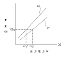
そして、図17において、L3は、画像形成ユニット20Yより下流側の画像形成ユニットのトナーの色がマゼンタ、シアン、ブラックである場合に、100〔%〕の印刷デューティでに形成された濃度検出パターンPt1の濃度を検出したときの、出力電圧YV100
3と濃度YOD100 との関係を表す線であり、L4は、画像形成ユニット20Yより下流側の画像形成ユニットのトナーの色がマゼンタ、シアン、ホワイトである場合に、100〔%〕の印刷デューティで形成された濃度検出パターンPt1の濃度を検出したときの、出力電圧YV100
3' と濃度YOD100 との関係を表す線である。
Then, in FIG. 17, L3 is a density detection pattern formed with a print duty of 100 [%] when the toner color of the image forming unit downstream of the
前記廃棄トナー量算出処理部Pr2は、図17に示される出力電圧YV100
3' に基づいて中間転写ベルト35上のトナー像の質量Gbを算出し、濃度YOD100
3に基づいて用紙P上のトナー像の質量Gpを算出し、二次転写効率YK3
YK3 =100×Gp/Gb
=100×(α×YV100
3+β)/(γ×YOD100
3+ε)
を算出する。この場合も、前記出力電圧YV100
3は、濃度補正処理が行われるときの濃度センサ44のセンサ出力の出力電圧であり、濃度YOD100
3を、前記濃度算出用係数テーブルTb3から読み出された係数Y3 (A)、Y3 (B)に基づいて算出することができる。
The waste toner amount calculation processing unit Pr2 calculates the mass Gb of the toner image on the
YK 3 = 100 × Gp / Gb
= 100 × (α × YV 100 3 + β) / (γ × YOD 100 3 + ε)
Is calculated. Also in this case, the output voltage YV 100 3 is the output voltage of the sensor output of the
また、廃棄トナー量算出処理部Pr2は、図17に示される出力電圧YV100
3' に基づいて中間転写ベルト35上のトナー像の質量Gbを算出し、濃度YOD100
3' に基づいて用紙P上のトナー像の質量Gpを算出し、二次転写効率YK3'
YK3'=100×Gp/Gb
=100×(α×YV100
3' +β)/(γ×YOD100
3' +ε)
を算出する。この場合も、前記出力電圧YV100
3' は、濃度補正処理が行われるときの濃度センサ44のセンサ出力の出力電圧であり、濃度YOD100
3' を、前記濃度算出用係数テーブルTb3から読み出された係数Y3 (A)、Y3 (B)に基づいて算出することができる。
Further, the waste toner amount calculation processing unit Pr2 calculates the mass Gb of the toner image on the
YK 3' = 100 x Gp / Gb
= 100 x (α x YV 100 3' + β) / (γ x YOD 100 3' + ε)
Is calculated. Also in this case, the output voltage YV 100 3'is the output voltage of the sensor output of the
したがって、廃棄トナー量算出処理部Pr2は、一次転写効率η1及び二次転写効率YK3 に基づいて、廃棄トナーの量δYD
δYD=δW×η1×(100-YK3 )
を算出し、一次転写効率η1及び二次転写効率YK3'に基づいて、廃棄トナーの量δYD
δYD=δW×η1×(100-YK3')
を算出する。
Therefore, the waste toner amount calculation processing unit Pr2 has a waste toner amount δYD based on the primary transfer efficiency η1 and the secondary transfer efficiency YK3.
δYD = δW × η1 × (100-YK 3 )
Is calculated, and the amount of waste toner δYD is based on the primary transfer efficiency η1 and the secondary transfer efficiency YK 3' .
δYD = δW × η1 × (100-YK 3 ′ )
Is calculated.
このように、本実施の形態においては、各画像形成ユニット20Y、20M、20C、20Bk、20Wの位置及びアップダウン状態、並びに濃度センサ44のセンサ出力の出力電圧に基づいて算出された濃度検出パターンPt1の濃度に基づいて、用紙Pに形成されるカラーの画像の濃度が補正され、出力電圧及び濃度検出パターンPt1の濃度に基づいて、印刷に伴って生じる廃棄トナーの量δDが算出されるので、操作者が各画像形成ユニット20Y、20M、20C、20Bk、20Wの位置を変更したり、所定の画像形成ユニットをアップ状態に置いたりしたときに、二次転写が行われるときの二次転写効率が変化しても、廃棄トナーの量δDを正確に算出することができる。
As described above, in the present embodiment, the density detection pattern calculated based on the position and up / down state of each
したがって、廃棄トナータンク48の残容積Uxが正確に算出されるので、操作者に廃棄トナータンク48の交換が適正に促される。
Therefore, since the remaining volume Ux of the
なお、本実施の形態においては、図9に示されるように、濃度検出パターンPt1が15個の検出部位から成るが、検出部位の数を多くすることができる。 In the present embodiment, as shown in FIG. 9, the concentration detection pattern Pt1 is composed of 15 detection sites, but the number of detection sites can be increased.
図18は本発明の実施の形態における濃度検出パターンの他の例を示す図である。 FIG. 18 is a diagram showing another example of the concentration detection pattern in the embodiment of the present invention.
図において、Pt2は濃度検出パターンであり、該濃度検出パターンPt2は、中間転写ベルト35の走行方向(矢印C方向)に延在させて形成され、Lp〔mm〕の長さを有する30個の検出部位から成る。
In the figure, Pt2 is a concentration detection pattern, and the concentration detection pattern Pt2 is formed so as to extend in the traveling direction (arrow C direction) of the
各検出部位において、Y、M、C、K、Wはイエロー、マゼンタ、シアン、ブラック及びホワイトの色を表し、15%、30%、50%、70%、85%、100%は印刷デューティを表す。 At each detection site, Y, M, C, K, W represent yellow, magenta, cyan, black and white colors, and 15%, 30%, 50%, 70%, 85% and 100% have print duty. show.
このように、検出部位の数を多くすると、濃度検出パターンPt2の濃度を詳細に算出することができるので、濃度補正処理を精度良く行うことができる。 By increasing the number of detection sites in this way, the concentration of the concentration detection pattern Pt2 can be calculated in detail, so that the concentration correction process can be performed with high accuracy.
また、本実施の形態においては、特色トナーとしてホワイトのトナーが使用されるようになっているが、光輝性を有するトナー、クリアなトナー等を特色トナーとして使用することができる。 Further, in the present embodiment, white toner is used as the special color toner, but a toner having brilliance, a clear toner, or the like can be used as the special color toner.
さらに、前記実施の形態においてはプリンタ10について説明しているが、本発明を複写機、ファクシミリ、複合機等の画像形成装置に適用することができる。
Further, although the
なお、本発明は前記実施の形態に限定されるものではなく、本発明の趣旨に基づいて種々変形させることが可能であり、それらを本発明の範囲から排除するものではない。 The present invention is not limited to the above-described embodiment, and various modifications can be made based on the gist of the present invention, and these are not excluded from the scope of the present invention.
10 プリンタ
20Y、20M、20C、20Bk、20W 画像形成ユニット
21 感光体ドラム
24 LEDヘッド
27 現像ローラ
35 中間転写ベルト
41、43 転写ローラ
44 濃度センサ
45 第2のクリーニング装置
48 廃棄トナータンク
Bd 装置本体
P 用紙
Pr1 濃度補正処理部
Pr2 廃棄トナー量算出処理部
Pt1、Pt2 濃度検出パターン
10
Claims (10)
(b)該各画像形成ユニットの像担持体と対向させて配設され、画像信号に従って一つ以上の駆動素子を駆動し、像担持体の表面を露光して前記静電潜像を形成する露光装置と、
(c)各像担持体上に形成された現像剤像を中間転写部材に転写し、一次転写を行う第1の転写部材と、
(d)中間転写部材上の現像剤像を媒体に転写し、二次転写を行う第2の転写部材と、
(e)二次転写が行われた後に中間転写部材上に残留した現像剤像を除去し、廃棄現像剤収容部に収容するクリーニング装置と、
(f)中間転写部材上に形成された濃度検出パターンを検出するパターン検出部と、
(g)前記各画像形成ユニットの位置及び前記各画像形成ユニットの前記中間転写部材に対する離接状態、並びに前記パターン検出部のセンサ出力の出力電圧に基づいて算出された前記濃度検出パターンの濃度に基づいて、媒体に形成される画像の濃度を補正する濃度補正処理部と、
(h)前記出力電圧及び前記濃度検出パターンの濃度に基づいて、印刷に伴って生じる廃棄現像剤の量を算出し、該廃棄現像剤の量に基づいて廃棄現像剤収容部における廃棄現像剤の収容状態を算出し、操作者に通知する廃棄現像剤量算出処理部とを有することを特徴とする画像形成装置。 (A) A plurality of image carriers and a developer carrier that develops an electrostatic latent image formed on the image carrier to form a developer image and is movably arranged with respect to the main body of the apparatus. Image forming unit and
(B) Arranged so as to face the image carrier of each image carrier, one or more drive elements are driven according to the image signal, and the surface of the image carrier is exposed to form the electrostatic latent image. With the exposure equipment
(C) A first transfer member that transfers the developer image formed on each image carrier to an intermediate transfer member and performs primary transfer, and
(D) A second transfer member that transfers the developer image on the intermediate transfer member to a medium and performs secondary transfer, and
(E) A cleaning device that removes the developer image remaining on the intermediate transfer member after the secondary transfer is performed and stores it in the waste developer storage unit.
(F) A pattern detection unit that detects the concentration detection pattern formed on the intermediate transfer member, and
(G) To the density of the density detection pattern calculated based on the position of each image forming unit, the detached state of each image forming unit with respect to the intermediate transfer member, and the output voltage of the sensor output of the pattern detection unit. Based on the density correction processing unit that corrects the density of the image formed on the medium,
(H) The amount of the waste developer generated by printing is calculated based on the output voltage and the density of the density detection pattern, and the waste developer in the waste developer storage unit is calculated based on the amount of the waste developer. An image forming apparatus including a waste developer amount calculation processing unit that calculates an accommodation state and notifies the operator.
(b)該各画像形成ユニットの像担持体と対向させて配設され、画像信号に従って一つ以上の駆動素子を駆動し、像担持体の表面を露光して前記静電潜像を形成する露光装置と、
(c)各像担持体上に形成された現像剤像を中間転写部材に転写し、一次転写を行う第1の転写部材と、
(d)中間転写部材上の現像剤像を媒体に転写し、二次転写を行う第2の転写部材と、
(e)二次転写が行われた後に中間転写部材上に残留した現像剤像を除去し、廃棄現像剤収容部に収容するクリーニング装置と、
(f)中間転写部材上に形成された濃度検出パターンを検出するパターン検出部と、
(g)前記各画像形成ユニットの位置及び離接状態、並びに前記パターン検出部のセンサ出力の出力電圧に基づいて算出された前記濃度検出パターンの濃度に基づいて、媒体に形成される画像の濃度を補正する濃度補正処理部と、
(h)前記出力電圧及び前記濃度検出パターンの濃度に基づいて、印刷に伴って生じる廃棄現像剤の量を算出し、該廃棄現像剤の量に基づいて廃棄現像剤収容部における廃棄現像剤の収容状態を算出し、操作者に通知する廃棄現像剤量算出処理部とを有するとともに、
(i)前記濃度補正処理部は、前記パターン検出部のセンサ出力の出力電圧に基づいて算出された前記濃度検出パターンの濃度と目標印刷濃度との差分に基づいて、前記露光装置の駆動素子の駆動時間を補正することを特徴とする画像形成装置。 (A) A plurality of image carriers and a developer carrier that develops an electrostatic latent image formed on the image carrier to form a developer image and is movably arranged with respect to the main body of the apparatus. Image forming unit and
(B) Arranged so as to face the image carrier of each image carrier, one or more drive elements are driven according to the image signal, and the surface of the image carrier is exposed to form the electrostatic latent image. With the exposure equipment
(C) A first transfer member that transfers the developer image formed on each image carrier to an intermediate transfer member and performs primary transfer, and
(D) A second transfer member that transfers the developer image on the intermediate transfer member to a medium and performs secondary transfer, and
(E) A cleaning device that removes the developer image remaining on the intermediate transfer member after the secondary transfer is performed and stores it in the waste developer storage unit.
(F) A pattern detection unit that detects the concentration detection pattern formed on the intermediate transfer member, and
(G) The density of the image formed on the medium based on the position and the detached state of each image forming unit and the density of the density detection pattern calculated based on the output voltage of the sensor output of the pattern detection unit. The density correction processing unit that corrects
(H) The amount of the waste developer generated by printing is calculated based on the output voltage and the density of the density detection pattern, and the waste developer in the waste developer storage unit is calculated based on the amount of the waste developer. It has a waste developer amount calculation processing unit that calculates the accommodation state and notifies the operator, and also has a waste developer amount calculation processing unit.
(I) The density correction processing unit is a drive element of the exposure apparatus based on the difference between the density of the density detection pattern and the target print density calculated based on the output voltage of the sensor output of the pattern detection unit. An image forming apparatus characterized in that the drive time is corrected.
(b)該各画像形成ユニットの像担持体と対向させて配設され、画像信号に従って一つ以上の駆動素子を駆動し、像担持体の表面を露光して前記静電潜像を形成する露光装置と、
(c)各像担持体上に形成された現像剤像を中間転写部材に転写し、一次転写を行う第1の転写部材と、
(d)中間転写部材上の現像剤像を媒体に転写し、二次転写を行う第2の転写部材と、
(e)二次転写が行われた後に中間転写部材上に残留した現像剤像を除去し、廃棄現像剤収容部に収容するクリーニング装置と、
(f)中間転写部材上に形成された濃度検出パターンを検出するパターン検出部と、
(g)前記各画像形成ユニットの位置及び離接状態、並びに前記パターン検出部のセンサ出力の出力電圧に基づいて算出された前記濃度検出パターンの濃度に基づいて、媒体に形成される画像の濃度を補正する濃度補正処理部と、
(h)前記出力電圧及び前記濃度検出パターンの濃度に基づいて、印刷に伴って生じる廃棄現像剤の量を算出し、該廃棄現像剤の量に基づいて廃棄現像剤収容部における廃棄現像剤の収容状態を算出し、操作者に通知する廃棄現像剤量算出処理部とを有するとともに、
(i)該廃棄現像剤量算出処理部は、前記パターン検出部のセンサ出力の出力電圧、及び各画像形成ユニットより下流側においてダウン状態に置かれた画像形成ユニットにおいて現像剤像が形成される現像剤の色に基づいて濃度検出パターンの濃度を算出し、該濃度検出パターンの濃度に基づいて算出した媒体上の現像剤像の質量、及び前記出力電圧に基づいて算出した中間転写部材上の現像剤像の質量に基づいて廃棄現像剤の量を算出することを特徴とする画像形成装置。 (A) A plurality of image carriers and a developer carrier that develops an electrostatic latent image formed on the image carrier to form a developer image and is movably arranged with respect to the main body of the apparatus. Image forming unit and
(B) Arranged so as to face the image carrier of each image carrier, one or more drive elements are driven according to the image signal, and the surface of the image carrier is exposed to form the electrostatic latent image. With the exposure equipment
(C) A first transfer member that transfers the developer image formed on each image carrier to an intermediate transfer member and performs primary transfer, and
(D) A second transfer member that transfers the developer image on the intermediate transfer member to a medium and performs secondary transfer, and
(E) A cleaning device that removes the developer image remaining on the intermediate transfer member after the secondary transfer is performed and stores it in the waste developer storage unit.
(F) A pattern detection unit that detects the concentration detection pattern formed on the intermediate transfer member, and
(G) The density of the image formed on the medium based on the position and the detached state of each image forming unit and the density of the density detection pattern calculated based on the output voltage of the sensor output of the pattern detection unit. The density correction processing unit that corrects
(H) The amount of the waste developer generated by printing is calculated based on the output voltage and the density of the density detection pattern, and the waste developer in the waste developer storage unit is calculated based on the amount of the waste developer. It has a waste developer amount calculation processing unit that calculates the accommodation state and notifies the operator, and also has a waste developer amount calculation processing unit.
(I) In the waste developer amount calculation processing unit, a developer image is formed in the output voltage of the sensor output of the pattern detection unit and the image forming unit placed in the down state on the downstream side of each image forming unit. The density of the density detection pattern is calculated based on the color of the developer, the mass of the developer image on the medium calculated based on the density of the density detection pattern, and the intermediate transfer member calculated based on the output voltage. An image forming apparatus characterized in that the amount of waste developer is calculated based on the mass of the developer image.
Priority Applications (1)
| Application Number | Priority Date | Filing Date | Title |
|---|---|---|---|
| JP2018203169A JP7087914B2 (en) | 2018-10-29 | 2018-10-29 | Image forming device |
Applications Claiming Priority (1)
| Application Number | Priority Date | Filing Date | Title |
|---|---|---|---|
| JP2018203169A JP7087914B2 (en) | 2018-10-29 | 2018-10-29 | Image forming device |
Publications (2)
| Publication Number | Publication Date |
|---|---|
| JP2020071268A JP2020071268A (en) | 2020-05-07 |
| JP7087914B2 true JP7087914B2 (en) | 2022-06-21 |
Family
ID=70549462
Family Applications (1)
| Application Number | Title | Priority Date | Filing Date |
|---|---|---|---|
| JP2018203169A Active JP7087914B2 (en) | 2018-10-29 | 2018-10-29 | Image forming device |
Country Status (1)
| Country | Link |
|---|---|
| JP (1) | JP7087914B2 (en) |
Citations (5)
| Publication number | Priority date | Publication date | Assignee | Title |
|---|---|---|---|---|
| JP2000147828A (en) | 1998-06-24 | 2000-05-26 | Canon Inc | Toner and image forming method |
| JP2002023459A (en) | 2000-07-06 | 2002-01-23 | Fujitsu Ltd | Color image forming device |
| JP2004240369A (en) | 2003-02-10 | 2004-08-26 | Canon Inc | Image forming apparatus |
| JP2009217163A (en) | 2008-03-12 | 2009-09-24 | Oki Data Corp | Image forming apparatus and image forming method |
| JP2016177122A (en) | 2015-03-20 | 2016-10-06 | 株式会社沖データ | Image forming apparatus |
-
2018
- 2018-10-29 JP JP2018203169A patent/JP7087914B2/en active Active
Patent Citations (5)
| Publication number | Priority date | Publication date | Assignee | Title |
|---|---|---|---|---|
| JP2000147828A (en) | 1998-06-24 | 2000-05-26 | Canon Inc | Toner and image forming method |
| JP2002023459A (en) | 2000-07-06 | 2002-01-23 | Fujitsu Ltd | Color image forming device |
| JP2004240369A (en) | 2003-02-10 | 2004-08-26 | Canon Inc | Image forming apparatus |
| JP2009217163A (en) | 2008-03-12 | 2009-09-24 | Oki Data Corp | Image forming apparatus and image forming method |
| JP2016177122A (en) | 2015-03-20 | 2016-10-06 | 株式会社沖データ | Image forming apparatus |
Also Published As
| Publication number | Publication date |
|---|---|
| JP2020071268A (en) | 2020-05-07 |
Similar Documents
| Publication | Publication Date | Title |
|---|---|---|
| JP4789534B2 (en) | Image forming apparatus | |
| US8391749B2 (en) | Image forming apparatus, image forming unit, and erase light control method | |
| JP4855430B2 (en) | Image forming apparatus | |
| JPH11161042A (en) | Image forming device | |
| JP2009163030A (en) | Image forming apparatus and drive control method therefor | |
| JP4392234B2 (en) | Image forming apparatus and toner supply method | |
| JP2006235391A (en) | Image forming apparatus | |
| JP2006227325A (en) | Image forming apparatus | |
| JP4598045B2 (en) | Image forming apparatus and image forming apparatus cleaning method | |
| US20140233987A1 (en) | Image forming apparatus | |
| US9091962B2 (en) | Cartridge, developing cartridge, process cartridge and image forming apparatus | |
| JP2006235009A (en) | Color image forming apparatus | |
| JP7087914B2 (en) | Image forming device | |
| JP2012247627A (en) | Image forming device | |
| US9933724B2 (en) | Image forming apparatus and image forming method with developing voltage correction processing | |
| JP2007010744A (en) | Image forming apparatus and resist adjustment method for the device | |
| JP2016130830A (en) | Image forming apparatus | |
| JP2007025205A (en) | Image forming apparatus and its control method | |
| US20070104514A1 (en) | Image forming method and printing method thereof | |
| JP2005352379A (en) | Image forming apparatus | |
| US8977152B2 (en) | Image forming apparatus having developer stirring control | |
| JP4710346B2 (en) | Image forming apparatus and color misregistration correction method | |
| JP5073586B2 (en) | Image forming apparatus | |
| JP2006018007A (en) | Image forming apparatus | |
| JP2006078658A (en) | Color image forming apparatus |
Legal Events
| Date | Code | Title | Description |
|---|---|---|---|
| A621 | Written request for application examination |
Free format text: JAPANESE INTERMEDIATE CODE: A621 Effective date: 20210303 |
|
| A711 | Notification of change in applicant |
Free format text: JAPANESE INTERMEDIATE CODE: A712 Effective date: 20210616 |
|
| A977 | Report on retrieval |
Free format text: JAPANESE INTERMEDIATE CODE: A971007 Effective date: 20220125 |
|
| A131 | Notification of reasons for refusal |
Free format text: JAPANESE INTERMEDIATE CODE: A131 Effective date: 20220201 |
|
| A521 | Request for written amendment filed |
Free format text: JAPANESE INTERMEDIATE CODE: A523 Effective date: 20220330 |
|
| TRDD | Decision of grant or rejection written | ||
| A01 | Written decision to grant a patent or to grant a registration (utility model) |
Free format text: JAPANESE INTERMEDIATE CODE: A01 Effective date: 20220510 |
|
| A61 | First payment of annual fees (during grant procedure) |
Free format text: JAPANESE INTERMEDIATE CODE: A61 Effective date: 20220523 |
|
| R150 | Certificate of patent or registration of utility model |
Ref document number: 7087914 Country of ref document: JP Free format text: JAPANESE INTERMEDIATE CODE: R150 |