EP1541971B1 - Encoder with noise detection - Google Patents
Encoder with noise detection Download PDFInfo
- Publication number
- EP1541971B1 EP1541971B1 EP04028467A EP04028467A EP1541971B1 EP 1541971 B1 EP1541971 B1 EP 1541971B1 EP 04028467 A EP04028467 A EP 04028467A EP 04028467 A EP04028467 A EP 04028467A EP 1541971 B1 EP1541971 B1 EP 1541971B1
- Authority
- EP
- European Patent Office
- Prior art keywords
- noise
- encoder
- signal
- detecting means
- movement
- Prior art date
- Legal status (The legal status is an assumption and is not a legal conclusion. Google has not performed a legal analysis and makes no representation as to the accuracy of the status listed.)
- Expired - Fee Related
Links
Images


Classifications
-
- G—PHYSICS
- G01—MEASURING; TESTING
- G01D—MEASURING NOT SPECIALLY ADAPTED FOR A SPECIFIC VARIABLE; ARRANGEMENTS FOR MEASURING TWO OR MORE VARIABLES NOT COVERED IN A SINGLE OTHER SUBCLASS; TARIFF METERING APPARATUS; MEASURING OR TESTING NOT OTHERWISE PROVIDED FOR
- G01D5/00—Mechanical means for transferring the output of a sensing member; Means for converting the output of a sensing member to another variable where the form or nature of the sensing member does not constrain the means for converting; Transducers not specially adapted for a specific variable
- G01D5/12—Mechanical means for transferring the output of a sensing member; Means for converting the output of a sensing member to another variable where the form or nature of the sensing member does not constrain the means for converting; Transducers not specially adapted for a specific variable using electric or magnetic means
- G01D5/244—Mechanical means for transferring the output of a sensing member; Means for converting the output of a sensing member to another variable where the form or nature of the sensing member does not constrain the means for converting; Transducers not specially adapted for a specific variable using electric or magnetic means influencing characteristics of pulses or pulse trains; generating pulses or pulse trains
- G01D5/24471—Error correction
- G01D5/24476—Signal processing
Definitions
- the present invention relates to an encoder such as a rotary encoder, a linear scale, and the like, and, more particularly, to an encoder that can output the information of noise level.
- Encoders are well known in the prior art as devices for detecting the moving position or the amount of displacement of a moving body, and can be roughly classified into two types: rotary encoders are encoders that detect the angle of rotation or the amount of rotation; and linear scales are encoders that detect the position or the amount of displacement from a reference position along a path.
- an encoder is mounted on the housing of a driving device such as a motor that drives a moving body.
- An encoder contains a circuit board, and a signal processing circuit is mounted on this circuit board.
- a driving device such as a motor that drives a moving body.
- An encoder contains a circuit board, and a signal processing circuit is mounted on this circuit board.
- a signal processing circuit is mounted on this circuit board.
- the encoder circuit may be affected via the stray capacitance, to cause an error in the position data or displacement amount data that the encoder outputs.
- Figure 11 is a schematic diagram for explaining a prior art encoder.
- the encoder 101 comprises a movement detecting means 102 for detecting the movement of a moving body 10 and a signal processing circuit 103 for generating an encoder signal by processing the movement detection signal supplied from the movement detecting means 102; here, the signal processing circuit 103 is mounted on a circuit board 106.
- the movement of the moving body 10 driven by a driving device 11 such as a motor is detected by the movement detecting means 102, and the encoder signal is generated by the signal processing circuit 103.
- Figure 12 is a schematic diagram for explaining how the prior art encoder is mounted on a housing.
- the encoder is mounted on the housing 13 of the driving device (hereinafter referred to as the motor) via an encoder flange 103a provided on the encoder.
- the encoder flange 103a is fixed to the motor housing 13 with flange fixing screws 103b, and the circuit board 106 is fixed to the encoder flange 103a with circuit board fixing screws 103d.
- a rotating slit 103c is mounted between the circuit board 106 and the encoder flange 103a.
- Figure 13 shows one example of noise occurring in the motor housing.
- the noise is measured by directly measuring a noise potential with a potential measuring means 104 connected between the motor housing 13 and a 0-volt point on the circuit.
- the measured noise potential is used to take remedial measures against the noise based on the level of the noise potential.
- noise potential difference
- This noise may affect the encoder circuit via the stray capacitance, causing an error in the position data or displacement amount data that the encoder produces.
- the potential of the motor housing is directly measured using a measuring device, and remedial measures are taken to reduce the noise by making a judgment based on the noise level obtained through the measurement.
- a noise voltage generated within the encoder via a stray capacitance is detected within the encoder and is output as noise data, so that the noise level can be detected without requiring the use of an external measuring device.
- Patent Abstracts of Japan concerning JP A 56 083804 discloses to improve the signal to noise ratio by reading a noise level immediately before a signal medium reaches a signal sensor to determine a difference from the subsequent detection output signal. More specifically, it is disclosed that a sheet paper is moved through a conveying path. A position sensor and a signal sensor are arranged on this path. In reaction to detection signals from the position sensor, an integrating reset timing signal is generated cyclically by a timing generation circuit while outputs of the signal sensor are fed to an integrator to draw an integration signal each time the signal is applied. A noise level is extracted from the outputs immediately before the sheet paper reaches the signal sensor to detect a difference from the detection signal when the sheet paper reaches the signal sensor.
- EP 1 103 790 A2 relates to the detection and analysis of motion. It is particularly concerned with detection of motion measured by interferometer or encoder systems.
- the system is described to be less susceptible to noise than traditional system. If the system produces a valid result in one measurement system then the result is valid. A definition of acceptable noise can then be obtained by considering whether the measurement point is doser to the segment boundary which would correspond to a valid measurement, or close to the segment boundary which would result in the measurement being invalid in both coordinate systems. The former can then be assumed to be a valid measurement affected by noise, and the measurement treated as if it is in a valid segment, whereas the latter can be treated as an invalid measurement.
- This system analyses on the basis of a high resolution coordinate axes system.
- That coordinate axes system will need at least six axes.
- the system allows for the detection of over speed in a situation where any individual measurement is affected by noise, and it is possible to allow for measurements which could represent over speed, or could represent measurements represented by noise. It is then possible to adjust the levels of acceptable noise/levels of invalidity acceptable.
- DE 197 33 904 A1 is concerned with a magnetic detecting apparatus that permits accurate waveform processing free from the influences of noise signals or the like by setting the voltage shifting amount of a level shifting circuit to a fixed value rather than depending on the level of an analog signal.
- This magnetic detecting apparatus permits accurate waveform processing by setting the hysteresis width of a hysteresis generating circuit to a fixed value.
- a magnetic detecting apparatus having a magnetoresistive element disposed to be opposed to a magnetic body, a magnet for applying a bias magnetic field to the magnetoresistive element, and a waveform processing circuit for waveform-shaping an analog signal, which is output from the magnetoresistive element as the magnetic body moves, into a pulse signal.
- the waveform processing circuit includes an amplifier circuit for amplifying the analog signal obtained from the magnetoresistive element in synchronization with the movement of the magnetic body
- a level shifting circuit is connected to an output terminal of the amplifier circuit that generates a first voltage signal output from the amplifier circuit, a second voltage signal higher than the first voltage signal by a first predetermined voltage, and a third voltage signal lower than the first voltage signal by a second predetermined voltage.
- a voltage retaining circuit alternately retains the minimum value of the second voltage signal and the maximum value of the third voltage signal as a reference voltage signal.
- a comparator circuit compares the first voltage signal with the reference voltage signal and issues a pulse signal.
- the level shifting circuit is composed of first and second resistors which are respectively inserted between the output terminal of the first voltage signal and the output terminals of the second and third voltage signals, to correspond to the first and second predetermined voltages.
- a constant-current circuit is connected in series to the first and second resistors.
- the encoder of the present invention is constructed by incorporating within the same apparatus: movement detecting means for detecting the movement of a moving body; a signal processing circuit for processing a movement detection signal supplied from the movement detecting means, and thereby producing an encoder signal representing the position and/or the amount of displacement of the moving body; and noise detecting means for detecting noise superimposed on the movement detection signal.
- the noise superimposed on the movement detection signal is extracted from the movement detection signal supplied from the movement detecting means, and the noise level of the extracted noise is detected.
- the noise detecting means extracts the signal by connecting a coupling capacitor to a signal line connecting between the movement detecting means and the signal processing circuit.
- a coupling capacitor By interposing the coupling capacitor, an AC component can be extracted from the movement detection signal flowing along the signal line.
- noise induced in a circuit board on which the signal processing circuit is mounted is extracted, and the noise level of the extracted noise is detected.
- the noise detecting means extracts the signal by connecting a coupling capacitor to an arbitrary signal line on the circuit board. By interposing the coupling capacitor, an AC component can be extracted from the signal output on the signal line.
- the signal flowing along the signal line contains a DC component and an AC component; the DC component represents the moving condition of the moving body, and the AC component represents the noise condition. Accordingly, in the first and second embodiments, by extracting the AC component via the coupling capacitor, the noise component can be detected.
- the encoder includes an A/D conversion circuit for obtaining the noise level from the extracted AC component.
- the encoder of the present invention further comprises transmitting means so that the output of the noise detecting means and/or the output of the signal processing circuit can be transmitted to a control unit for a driving device that drives the moving body.
- the output of the noise detecting means and the output of the signal processing circuit are data occurring at the same instant in time. Accordingly, when a noise component is detected in the output of the noise detecting means, it can be determined that the noise component is also superimposed on the output of the signal processing circuit transmitted at the same instant in time.
- the encoder of the present invention can also be constructed by connecting a capacitor between the circuit board and the driving device that drives the moving body.
- a capacitor between the circuit board and the driving device such as a motor
- only the AC component of the potential occurring in the driving device can be transmitted to the circuit board.
- the thus connected capacitor forms a parallel circuit with a stray capacitance between the circuit board and the driving device, and transmits the AC component of the potential occurring in the driving device to the circuit board.
- the accuracy of the detection performed by the noise detecting means can be enhanced.
- a noise amount detecting circuit may be connected between the circuit board and the driving device that drives the moving body.
- the movement detecting means can make use of an optical detection system, and can be constructed using a light emitting device, a code disk which transmits or reflects light emitted from the light emitting device, and a light receiving device which receives the light transmitted through or reflected by the code disk and outputs a light detecting signal.
- the movement detecting means may includes a light receiving device for measuring noise level; by using the output of the noise-level-measuring light receiving device, the level of the noise component only can be calculated.
- the presence of noise occurring within the encoder can be detected.
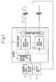
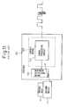
- Figure 1 is a schematic diagram for explaining a first embodiment of an encoder according to the present invention
- Figure 2 is a schematic diagram for explaining a second embodiment of an encoder according to the present invention.
- the encoder 1 comprises a movement detecting means 2 for detecting the movement of a moving body 10, a signal processing circuit 3 for outputting an encoder signal by processing the movement detection signal supplied from the movement detecting means 2, and a noise detecting means 4 for detecting a noise component contained in the movement detection signal; here, the movement detection signal is introduced into the noise detecting means 4 through a coupling capacitor 4a.
- the noise detecting means 4 detects the noise by extracting only the noise component contained in the movement detection signal.
- the encoder 1 comprises a movement detecting means 2 for detecting the movement of a moving body 10, a signal processing circuit 3 for outputting an encoder signal by processing the movement detection signal supplied from the movement detecting means 2, and a noise detecting means 4 for detecting a noise component contained in the movement detection signal; here, the signal flowing along a line 6b formed on the circuit board 6 on which the signal processing circuit 3 is mounted is introduced into the noise detecting means 4 through a coupling capacitor 4a.
- the noise detecting means 4 detects the noise by extracting only the noise component contained in the signal flowing along the line 6b formed on the circuit board 6.
- An arbitrary line formed on the circuit board 6 can be selected as the line 6b; here, by selecting a line that allows the detection of a constant voltage, for example, a line connected to a reference voltage 6a, the variation of the noise component can be detected stably.
- the moving body 10 is driven by a driving device 11 such as a motor, and the driving device 11 is controlled by a control unit 12.
- the control unit 12 controls the driving device 11 to control position, speed, etc. in response to the encoder signal acquired and fed back by the encoder 1.
- the feedback of the encoder signal is performed using a transmitting means 5 provided in the encoder 1.
- the transmitting means 5 can feed back to the control unit 12 not only the encoder signal output from the signal processing circuit 3 but also the noise data signal detected by the noise detecting means 4.
- the control unit 12 can determine, based on the fed back noise data signal, the presence or absence of a noise component in the encoder signal.
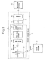
- Figures 3 and 4 are schematic diagrams for explaining configuration examples of the noise detecting means 4:
- Figure 3 shows a configuration example when transmitting only the noise data signal, and
- Figure 4 shows a configuration example when transmitting the encoder signal as well as the noise data signal.
- the noise detecting means 4 and the transmitting means 5 are shown mounted on the circuit board 6.
- the noise detecting means 4 comprises: the coupling capacitor 4a which is connected to the line connecting between the movement detecting means 2 and the signal processing circuit 3 or the line formed on the circuit board 6, and which extracts an AC component from the movement detection signal or from the signal flowing along the line formed on the circuit board; an amplifier 4b which amplifies the signal of the extracted AC component; a peak-hold circuit 4c which holds a peak value of the amplified signal; and an A/D conversion circuit 4d which converts the peak value into a digital signal to obtain the noise level.
- the transmitting means 5 transmits the noise level to a receiving section 12a in the control unit 12.
- the transmitting means 5 can be constructed using, for example, a signal processing LSI 5a and a transmitting driver 5b.
- the signal processing circuit 3, the noise detecting means 4, and the transmitting means 5 are shown mounted on the circuit board 6.
- the signal processing circuit 3 comprises a position signal creating means 3a for creating, from the movement detection signal, a position signal expressed in the form of a sin signal or a cos signal, and an A/D conversion circuit 3b which converts the position signal into a digital signal to produce the encoder signal.
- the transmitting means 5 can be constructed using a signal processing LSI 5a and a transmitting driver 5b; here, the LSI 5a creates a transmission signal by combining the noise level supplied from the noise detecting means 4 with the encoder signal supplied from the signal processing circuit 3, and transmits the noise level together with the encoder signal to the receiving section 12a of the control unit 12.
- the LSI 5a creates the transmission signal by converting the encoder signal and the noise level, occurring at the same instant in time, into a serial signal. As a result, the receiving section 12a can acquire the encoder signal and the noise level occurring at the same instant in time.
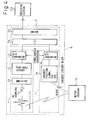
- Figure 5 is a schematic cross-sectional view for explaining how the encoder is mounted on the driving device.
- the encoder is mounted on the driving device such as a motor by fixing an encoder flange 1a to the housing 13 with flange fixing screws 1b.
- the circuit board 6 is fixed to the encoder flange 1a with circuit board fixing screws 1d.
- a rotating slit 1c is mounted between the circuit board 6 and the encoder flange 1a.
- the encoder can be constructed so that the potential on the housing 13 is introduced into the circuit board 6 not only via a stray capacitance 20 but also via a capacitor 7 connected between the housing 13 and the circuit board 6. This capacitor 7 is mounted on the circuit board 6.
- Figure 6 is a diagram showing a mounting example of a noise amount detection circuit.
- the noise amount detection circuit 14, which is mounted on the circuit board 6, is a circuit for roughly calculating the amount of noise introduced from the housing 13 into the circuit board 6, and is constructed by connecting a diode 15 in series to a parallel circuit of a capacitor 16 and a resistor 17.
- the noise amount detection circuit 14 has a detecting function for extracting a crest of an AC signal.
- the noise generated in the housing 13 is converted into a value representing the crest of the noise as it is passed through the noise amount detection circuit 14, and the value is fed into the circuit board 6.
- the noise detecting means 4 can detect an amount equivalent to the amount of noise.
- Figures 7A and 7B are diagrams for explaining a mounting example of the capacitor 7:
- Figure 7A is a top plan view of the circuit board 6, and
- Figure 7B is a cross-sectional view of a portion of the circuit board 6.
- a plated through hole 8 is formed in the circuit board 6 on which the capacitor 7 is mounted. One end of the capacitor 7 is connected to a 0-V potential point on the circuit board 6, while the other end is connected to an upper plated portion 8a of the plated through hole 8 via a connecting lead 9.
- the plated through hole 8 is a hole opened from the top through to the bottom of the circuit board 6, and its upper plated portion 8a and plated sidewall portions 8b are plated with metal, forming an electrical conductive path passing through the circuit board 6.
- circuit board fixing screws 1d is screwed into the plated through hole 8 to fix the circuit board 6 to the encoder flange 1a.
- the circuit board 6 is electrically connected to the encoder flange 1a via the capacitor 7, the connecting lead 9, and the upper plated portion 8a and plated sidewall portions 8b of the plated through hole 8.
- the noise amount detection circuit of Figure 6 can be mounted on the circuit board 6, like the capacitor shown in Figures 7A and 7B .
- a detection device for the movement detecting means 2 used in the encoder of the present invention, use can be made of a detection device of any desired type, for example, an optical type or a magnetic type.
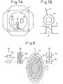
- Figure 8 is a schematic diagram for explaining one example of an optical-type movement detecting means incorporating a noise-measuring detection device.
- the movement detecting means includes a light emitting device 2a, a slit (code disk) 2b, 2c, and a light receiving device 2d.
- the light emitting device 2a comprises a position-detecting LED 2a1 and a noise-measuring LED 2a2.
- the slit comprises a fixed slit 2b and a rotating slit 2c; the fixed slit 2b includes a position-detecting split portion 2b1 and a noise-measuring slit portion 2b2, and the rotating slit 2c includes a position-detecting split portion 2c1 and a noise-measuring slit portion 2c2.
- the light receiving device 2d comprises a position-detecting light receiving device 2d1 and a noise-measuring light receiving device 2d2.
- the fixed slit 2b and the rotating slit 2c can be provided with a reference slit for detecting a reference position.
- the noise-measuring slit portion 2c2 is formed so as to always direct the light to the noise-measuring light receiving device 2d2, which thus receives the light emitted from the noise-measuring LED 2a2, irrespective of the rotational position of the rotating slit 2c.
- Figure 9 is a diagram for explaining an output signal that the light receiving device produces.
- the photocurrent produced by the photodiode is detected as a voltage signal.
- the voltage signal contains the detection signal plus the noise component superimposed on it.
- the noise component occurs independently of the current that the light receiving device produces by receiving light, and the same noise component is superimposed in the position-detecting light receiving device 2d1 as in the noise-measuring light receiving device 2d2.
- the detection signal from the noise-measuring light receiving device 2d2 represents the noise component contained in the detection signal from the position-detecting light receiving device 2d1.
- the noise level can thus be calculated based on the output of the noise-measuring light receiving device 2d2.
- FIG. 10 is a diagram for explaining the noise component on the line; for example, the AC component superimposed on a constant DC voltage of 2.5 V can be regarded as the noise component, and the noise component can be extracted by passing the signal through the coupling capacitor.
- the present invention can be applied not only to optical encoders but also to magnetic encoders, and is not restricted by the type of the movement detecting means.
- the invention can be applied not only to incremental encoders which measure relative amount such as revolutions or the amount of movement by counting signals, but also to absolute encoders which measure absolute position such as rotational angle or moving position.
- the invention can also be applied to rotary encoders which measure rotational position or the amount of rotation and linear encoders which measure moving position or the amount of movement along a straight line.
Landscapes
- Engineering & Computer Science (AREA)
- Signal Processing (AREA)
- Physics & Mathematics (AREA)
- General Physics & Mathematics (AREA)
- Transmission And Conversion Of Sensor Element Output (AREA)
- Optical Transform (AREA)
- Indication And Recording Devices For Special Purposes And Tariff Metering Devices (AREA)
Description
- The present invention relates to an encoder such as a rotary encoder, a linear scale, and the like, and, more particularly, to an encoder that can output the information of noise level.
- Encoders are well known in the prior art as devices for detecting the moving position or the amount of displacement of a moving body, and can be roughly classified into two types: rotary encoders are encoders that detect the angle of rotation or the amount of rotation; and linear scales are encoders that detect the position or the amount of displacement from a reference position along a path.
- Generally, an encoder is mounted on the housing of a driving device such as a motor that drives a moving body. An encoder contains a circuit board, and a signal processing circuit is mounted on this circuit board. Usually, there is no direct electrical connection between the circuit board contained in the encoder and the housing on which the encoder is mounted, but they are electrically connected indirectly via a stray capacitance.
- In this case, if a potential variation due to noise, etc. occurs on the housing side, the encoder circuit may be affected via the stray capacitance, to cause an error in the position data or displacement amount data that the encoder outputs.
-
Figure 11 is a schematic diagram for explaining a prior art encoder. InFigure 11 , theencoder 101 comprises a movement detecting means 102 for detecting the movement of a movingbody 10 and asignal processing circuit 103 for generating an encoder signal by processing the movement detection signal supplied from themovement detecting means 102; here, thesignal processing circuit 103 is mounted on acircuit board 106. - The movement of the moving
body 10 driven by adriving device 11 such as a motor is detected by the movement detecting means 102, and the encoder signal is generated by thesignal processing circuit 103. -
Figure 12 is a schematic diagram for explaining how the prior art encoder is mounted on a housing. The encoder is mounted on thehousing 13 of the driving device (hereinafter referred to as the motor) via an encoder flange 103a provided on the encoder. The encoder flange 103a is fixed to themotor housing 13 withflange fixing screws 103b, and thecircuit board 106 is fixed to the encoder flange 103a with circuitboard fixing screws 103d. Here, a rotatingslit 103c is mounted between thecircuit board 106 and the encoder flange 103a. -
Figure 13 shows one example of noise occurring in the motor housing. In the prior art, as shown inFigure 12 , for example, the noise is measured by directly measuring a noise potential with a potential measuring means 104 connected between themotor housing 13 and a 0-volt point on the circuit. The measured noise potential is used to take remedial measures against the noise based on the level of the noise potential. - Further, as a technique for detecting noise contained in the encoder signal, it is known to detect noise introduced in an encoder line along which the encoder signal is sent to the control unit (refer to Japanese Unexamined Patent Publication No.
2000-258481 - There is no direct electrical connection between the signal processing circuit in the encoder and the housing on which the encoder is mounted, but they are electrically connected indirectly via a stray capacitance.
- Accordingly, if the motor is not properly grounded, noise (potential difference) occurs in the housing. This noise may affect the encoder circuit via the stray capacitance, causing an error in the position data or displacement amount data that the encoder produces.
- In the prior art, the potential of the motor housing is directly measured using a measuring device, and remedial measures are taken to reduce the noise by making a judgment based on the noise level obtained through the measurement.
- The technique for measuring the noise introduced in the encoder line connecting between the encoder and the control unit is known in the above-cited Japanese Unexamined Patent Publication No.
2000-258481 - As the noise occurring within the encoder is included in the encoder signal itself, it is not possible to discriminate the noise from the signal representing the position data or displacement amount data of the moving body and, once output on the encoder line, the noise cannot be measured with the technique disclosed in Japanese Unexamined Patent Publication No.
2000-258481 - It is an object of the present invention to solve the above prior art problem and provide an encoder that can detect the presence of noise occurring within the encoder.
- According to the encoder of the present invention, a noise voltage generated within the encoder via a stray capacitance is detected within the encoder and is output as noise data, so that the noise level can be detected without requiring the use of an external measuring device.
- Further, by outputting encoder data and noise data Patent Abstracts of Japan concerning
JP A 56 083804 -
EP 1 103 790 A2 -
DE 197 33 904 A1 is concerned with a magnetic detecting apparatus that permits accurate waveform processing free from the influences of noise signals or the like by setting the voltage shifting amount of a level shifting circuit to a fixed value rather than depending on the level of an analog signal. This magnetic detecting apparatus permits accurate waveform processing by setting the hysteresis width of a hysteresis generating circuit to a fixed value. There is provided a magnetic detecting apparatus having a magnetoresistive element disposed to be opposed to a magnetic body, a magnet for applying a bias magnetic field to the magnetoresistive element, and a waveform processing circuit for waveform-shaping an analog signal, which is output from the magnetoresistive element as the magnetic body moves, into a pulse signal. The waveform processing circuit includes an amplifier circuit for amplifying the analog signal obtained from the magnetoresistive element in synchronization with the movement of the magnetic body A level shifting circuit is connected to an output terminal of the amplifier circuit that generates a first voltage signal output from the amplifier circuit, a second voltage signal higher than the first voltage signal by a first predetermined voltage, and a third voltage signal lower than the first voltage signal by a second predetermined voltage. A voltage retaining circuit alternately retains the minimum value of the second voltage signal and the maximum value of the third voltage signal as a reference voltage signal. A comparator circuit compares the first voltage signal with the reference voltage signal and issues a pulse signal. The level shifting circuit is composed of first and second resistors which are respectively inserted between the output terminal of the first voltage signal and the output terminals of the second and third voltage signals, to correspond to the first and second predetermined voltages. A constant-current circuit is connected in series to the first and second resistors. Thus, the voltage shift of the level shifting circuit is fixed regardless of the levels of the analog signals. Thereby, the magnetic detecting apparatus is capable of performing accurate waveform processing without being affected by noise signals or the like. occurring at the same instant in time, the reliability of the encoder data can be judged based on the condition of the noise level. - The encoder of the present invention is constructed by incorporating within the same apparatus: movement detecting means for detecting the movement of a moving body; a signal processing circuit for processing a movement detection signal supplied from the movement detecting means, and thereby producing an encoder signal representing the position and/or the amount of displacement of the moving body; and noise detecting means for detecting noise superimposed on the movement detection signal.
- In a first embodiment of the noise detection performed by the noise detecting means, the noise superimposed on the movement detection signal is extracted from the movement detection signal supplied from the movement detecting means, and the noise level of the extracted noise is detected.
- In the first embodiment, the noise detecting means extracts the signal by connecting a coupling capacitor to a signal line connecting between the movement detecting means and the signal processing circuit. By interposing the coupling capacitor, an AC component can be extracted from the movement detection signal flowing along the signal line.
- In a second embodiment of the noise detection performed by the noise detecting means, noise induced in a circuit board on which the signal processing circuit is mounted is extracted, and the noise level of the extracted noise is detected.
- In the second embodiment, the noise detecting means extracts the signal by connecting a coupling capacitor to an arbitrary signal line on the circuit board. By interposing the coupling capacitor, an AC component can be extracted from the signal output on the signal line.
- The signal flowing along the signal line contains a DC component and an AC component; the DC component represents the moving condition of the moving body, and the AC component represents the noise condition. Accordingly, in the first and second embodiments, by extracting the AC component via the coupling capacitor, the noise component can be detected.
- The encoder includes an A/D conversion circuit for obtaining the noise level from the extracted AC component.
- The encoder of the present invention further comprises transmitting means so that the output of the noise detecting means and/or the output of the signal processing circuit can be transmitted to a control unit for a driving device that drives the moving body.
- The output of the noise detecting means and the output of the signal processing circuit are data occurring at the same instant in time. Accordingly, when a noise component is detected in the output of the noise detecting means, it can be determined that the noise component is also superimposed on the output of the signal processing circuit transmitted at the same instant in time.
- The encoder of the present invention can also be constructed by connecting a capacitor between the circuit board and the driving device that drives the moving body. By connecting the capacitor between the circuit board and the driving device such as a motor, only the AC component of the potential occurring in the driving device can be transmitted to the circuit board. The thus connected capacitor forms a parallel circuit with a stray capacitance between the circuit board and the driving device, and transmits the AC component of the potential occurring in the driving device to the circuit board.
- By connecting the capacitor, the accuracy of the detection performed by the noise detecting means can be enhanced.
- Alternatively, a noise amount detecting circuit may be connected between the circuit board and the driving device that drives the moving body.
- The movement detecting means can make use of an optical detection system, and can be constructed using a light emitting device, a code disk which transmits or reflects light emitted from the light emitting device, and a light receiving device which receives the light transmitted through or reflected by the code disk and outputs a light detecting signal.
- The movement detecting means may includes a light receiving device for measuring noise level; by using the output of the noise-level-measuring light receiving device, the level of the noise component only can be calculated.
- According to the encoder of the present invention, the presence of noise occurring within the encoder can be detected.
- Further features and advantages of the present invention will be apparent from the following description with reference to the accompanying drawings, in which:
-
Figure 1 is a schematic diagram for explaining a first embodiment of an encoder according to the present invention; -
Figure 2 is a schematic diagram for explaining a second embodiment of an encoder according to the present invention; -
Figure 3 is a schematic diagram for explaining one configuration example of a noise detecting means that transmits only a noise data signal; -
Figure 4 is a schematic diagram for explaining one configuration example of a noise detecting means that transmits an encoder signal as well as a noise data signal; -
Figure 5 is a schematic cross-sectional view for explaining how the encoder is mounted on a driving device; -
Figure 6 is a schematic cross-sectional view for explaining an example in which a noise amount detection circuit is provided in the encoder. -
Figures 7A and 7B are diagrams for explaining a mounting example of a capacitor; -
Figure 8 is a schematic diagram for explaining one example of an optical-type movement detecting means; -
Figure 9 is a diagram for explaining an output signal that a light receiving device produces; -
Figure 10 is a diagram for explaining a noise component on a line; -
Figure 11 is a schematic diagram for explaining a prior art encoder; -
Figure 12 is a schematic diagram for explaining how the prior art encoder is mounted on a housing; and -
Figure 13 is a diagram showing one example of noise occurring in a motor housing. - An encoder according to the present invention will be described below with reference to the drawings.
-
Figure 1 is a schematic diagram for explaining a first embodiment of an encoder according to the present invention, andFigure 2 is a schematic diagram for explaining a second embodiment of an encoder according to the present invention. - In the first embodiment of the encoder shown in
Figure 1 , theencoder 1 comprises a movement detecting means 2 for detecting the movement of a movingbody 10, asignal processing circuit 3 for outputting an encoder signal by processing the movement detection signal supplied from themovement detecting means 2, and anoise detecting means 4 for detecting a noise component contained in the movement detection signal; here, the movement detection signal is introduced into thenoise detecting means 4 through acoupling capacitor 4a. By interposing thecoupling capacitor 4a, thenoise detecting means 4 detects the noise by extracting only the noise component contained in the movement detection signal. - On the other hand, in the second embodiment of the encoder shown in
Figure 2 , theencoder 1 comprises a movement detecting means 2 for detecting the movement of a movingbody 10, asignal processing circuit 3 for outputting an encoder signal by processing the movement detection signal supplied from themovement detecting means 2, and anoise detecting means 4 for detecting a noise component contained in the movement detection signal; here, the signal flowing along aline 6b formed on thecircuit board 6 on which thesignal processing circuit 3 is mounted is introduced into thenoise detecting means 4 through acoupling capacitor 4a. By interposing thecoupling capacitor 4a, thenoise detecting means 4 detects the noise by extracting only the noise component contained in the signal flowing along theline 6b formed on thecircuit board 6. - An arbitrary line formed on the
circuit board 6 can be selected as theline 6b; here, by selecting a line that allows the detection of a constant voltage, for example, a line connected to a reference voltage 6a, the variation of the noise component can be detected stably. - The moving
body 10 is driven by a drivingdevice 11 such as a motor, and the drivingdevice 11 is controlled by acontrol unit 12. Thecontrol unit 12 controls the drivingdevice 11 to control position, speed, etc. in response to the encoder signal acquired and fed back by theencoder 1. The feedback of the encoder signal is performed using a transmitting means 5 provided in theencoder 1. The transmitting means 5 can feed back to thecontrol unit 12 not only the encoder signal output from thesignal processing circuit 3 but also the noise data signal detected by thenoise detecting means 4. Thecontrol unit 12 can determine, based on the fed back noise data signal, the presence or absence of a noise component in the encoder signal. -
Figures 3 and4 are schematic diagrams for explaining configuration examples of the noise detecting means 4:Figure 3 shows a configuration example when transmitting only the noise data signal, andFigure 4 shows a configuration example when transmitting the encoder signal as well as the noise data signal. - In the example of
Figure 3 , thenoise detecting means 4 and the transmitting means 5 are shown mounted on thecircuit board 6. - The
noise detecting means 4 comprises: thecoupling capacitor 4a which is connected to the line connecting between themovement detecting means 2 and thesignal processing circuit 3 or the line formed on thecircuit board 6, and which extracts an AC component from the movement detection signal or from the signal flowing along the line formed on the circuit board; anamplifier 4b which amplifies the signal of the extracted AC component; a peak-hold circuit 4c which holds a peak value of the amplified signal; and an A/D conversion circuit 4d which converts the peak value into a digital signal to obtain the noise level. - The transmitting means 5 transmits the noise level to a receiving section 12a in the
control unit 12. The transmitting means 5 can be constructed using, for example, asignal processing LSI 5a and a transmittingdriver 5b. - In the example of
Figure 4 , thesignal processing circuit 3, thenoise detecting means 4, and the transmitting means 5 are shown mounted on thecircuit board 6. - For the
noise detecting means 4, the same configuration as that shown inFigure 3 can be employed, and therefore, the description thereof will not be repeated here. - The
signal processing circuit 3 comprises a position signal creating means 3a for creating, from the movement detection signal, a position signal expressed in the form of a sin signal or a cos signal, and an A/D conversion circuit 3b which converts the position signal into a digital signal to produce the encoder signal. - The transmitting means 5 can be constructed using a
signal processing LSI 5a and a transmittingdriver 5b; here, theLSI 5a creates a transmission signal by combining the noise level supplied from thenoise detecting means 4 with the encoder signal supplied from thesignal processing circuit 3, and transmits the noise level together with the encoder signal to the receiving section 12a of thecontrol unit 12. - The
LSI 5a creates the transmission signal by converting the encoder signal and the noise level, occurring at the same instant in time, into a serial signal. As a result, the receiving section 12a can acquire the encoder signal and the noise level occurring at the same instant in time. -
Figure 5 is a schematic cross-sectional view for explaining how the encoder is mounted on the driving device. InFigure 5 , the encoder is mounted on the driving device such as a motor by fixing anencoder flange 1a to thehousing 13 withflange fixing screws 1b. Thecircuit board 6 is fixed to theencoder flange 1a with circuitboard fixing screws 1d. Arotating slit 1c is mounted between thecircuit board 6 and theencoder flange 1a. - Here, the encoder can be constructed so that the potential on the
housing 13 is introduced into thecircuit board 6 not only via astray capacitance 20 but also via acapacitor 7 connected between thehousing 13 and thecircuit board 6. Thiscapacitor 7 is mounted on thecircuit board 6. -
Figure 6 is a diagram showing a mounting example of a noise amount detection circuit. The noiseamount detection circuit 14, which is mounted on thecircuit board 6, is a circuit for roughly calculating the amount of noise introduced from thehousing 13 into thecircuit board 6, and is constructed by connecting adiode 15 in series to a parallel circuit of acapacitor 16 and a resistor 17. - The noise
amount detection circuit 14 has a detecting function for extracting a crest of an AC signal. The noise generated in thehousing 13 is converted into a value representing the crest of the noise as it is passed through the noiseamount detection circuit 14, and the value is fed into thecircuit board 6. In this way, thenoise detecting means 4 can detect an amount equivalent to the amount of noise. -
Figures 7A and 7B are diagrams for explaining a mounting example of the capacitor 7:Figure 7A is a top plan view of thecircuit board 6, andFigure 7B is a cross-sectional view of a portion of thecircuit board 6. - A plated through
hole 8 is formed in thecircuit board 6 on which thecapacitor 7 is mounted. One end of thecapacitor 7 is connected to a 0-V potential point on thecircuit board 6, while the other end is connected to an upper platedportion 8a of the plated throughhole 8 via a connectinglead 9. The plated throughhole 8 is a hole opened from the top through to the bottom of thecircuit board 6, and its upper platedportion 8a and platedsidewall portions 8b are plated with metal, forming an electrical conductive path passing through thecircuit board 6. - One of the circuit
board fixing screws 1d is screwed into the plated throughhole 8 to fix thecircuit board 6 to theencoder flange 1a. In this way, thecircuit board 6 is electrically connected to theencoder flange 1a via thecapacitor 7, the connectinglead 9, and the upper platedportion 8a and platedsidewall portions 8b of the plated throughhole 8. - The noise amount detection circuit of
Figure 6 can be mounted on thecircuit board 6, like the capacitor shown inFigures 7A and 7B . - For the movement detecting means 2 used in the encoder of the present invention, use can be made of a detection device of any desired type, for example, an optical type or a magnetic type.
-
Figure 8 is a schematic diagram for explaining one example of an optical-type movement detecting means incorporating a noise-measuring detection device. - In
Figure 8 , the movement detecting means includes alight emitting device 2a, a slit (code disk) 2b, 2c, and alight receiving device 2d. Thelight emitting device 2a comprises a position-detecting LED 2a1 and a noise-measuring LED 2a2. The slit comprises a fixedslit 2b and arotating slit 2c; the fixedslit 2b includes a position-detecting split portion 2b1 and a noise-measuring slit portion 2b2, and therotating slit 2c includes a position-detecting split portion 2c1 and a noise-measuring slit portion 2c2. Thelight receiving device 2d comprises a position-detecting light receiving device 2d1 and a noise-measuring light receiving device 2d2. The fixedslit 2b and therotating slit 2c can be provided with a reference slit for detecting a reference position. - Light emitted from the position-detecting LED 2a1 is transmitted through or blocked (or reflected) by the slit depending on the positional relationship between the position-detecting split portion 2b1 and the position-detecting split portion 2c1, and the thus modulated light is detected by the position-detecting light receiving device 2d1; in this way, the position of the moving body can be detected from the rotational position of the
rotating slit 2c. - On the other hand, light emitted from the noise-measuring LED 2a2 is transmitted through the noise-measuring slit portion 2b2 and through the noise-measuring slit portion 2c2, and is detected by the noise-measuring light receiving device 2d2. In the
rotating slit 2c, the noise-measuring slit portion 2c2 is formed so as to always direct the light to the noise-measuring light receiving device 2d2, which thus receives the light emitted from the noise-measuring LED 2a2, irrespective of the rotational position of therotating slit 2c. -
Figure 9 is a diagram for explaining an output signal that the light receiving device produces. The photocurrent produced by the photodiode is detected as a voltage signal. The voltage signal contains the detection signal plus the noise component superimposed on it. The noise component occurs independently of the current that the light receiving device produces by receiving light, and the same noise component is superimposed in the position-detecting light receiving device 2d1 as in the noise-measuring light receiving device 2d2. - Accordingly, the detection signal from the noise-measuring light receiving device 2d2 represents the noise component contained in the detection signal from the position-detecting light receiving device 2d1. The noise level can thus be calculated based on the output of the noise-measuring light receiving device 2d2.
- On the other hand, on a line connected to a potential of a constant voltage, such as a reference voltage, on the circuit board, the AC component superimposed on the constant voltage can be regarded as the noise component.
Figure 10 is a diagram for explaining the noise component on the line; for example, the AC component superimposed on a constant DC voltage of 2.5 V can be regarded as the noise component, and the noise component can be extracted by passing the signal through the coupling capacitor. - The present invention can be applied not only to optical encoders but also to magnetic encoders, and is not restricted by the type of the movement detecting means.
- Further, the invention can be applied not only to incremental encoders which measure relative amount such as revolutions or the amount of movement by counting signals, but also to absolute encoders which measure absolute position such as rotational angle or moving position.
- The invention can also be applied to rotary encoders which measure rotational position or the amount of rotation and linear encoders which measure moving position or the amount of movement along a straight line.
- The present embodiment is to be considered in all respects as illustrative and not restrictive, the scope of the invention being indicated by the appended claims rather than by the foregoing description and all changes which come within the meaning and range of equivalency of the claims are therefore intended to be embraced therein.
Claims (8)
- An encoder incorporating within the same apparatus:movement detecting means (2) for detecting movement of a moving body (10);a signal processing circuit (3) for processing a movement detection signal supplied from said movement detecting means (2), and thereby producing an encoder signal representing the position and/or the amount of displacement of said moving body; characterized by noise detecting means (4) for detecting noise superimposed on said movement detection signal and for detecting noise level by extracting noise induced in a circuit board (6) on which said signal processing circuit (3) is mounted.
- An encoder as claimed in claim 1,
further characterized in that said noise detecting means (4) detects noise level by extracting the noise superimposed on said movement detection signal from said mouvement detection signal, wherein said noise detecting means (4) includes:a coupling capacitor (4a), connected to a signal line connecting between said movement detecting means (2) and said signal processing circuit (3), for extracting an AC component from said movement detection signal; and an A/D conversion circuit (4d) for obtaining said noise level from said extracted AC component. - An encoder as claimed in claim 2, characterized in that said noise detecting means (4) includes:a coupling capacitor (4a), connected to an arbitrary signal line (6b) on said circuit board (6), for extracting an AC component from a signal output on said signal line (6b); and an A/D conversion circuit (4d) for obtaining said noise level from said extracted AC component.
- An encoder as claimed in any one of claims 1 to 3, characterized in that it further comprises transmitting means (5) for transmitting an output of said noise detecting means (4) and/or an output of said signal processing circuit (3) to a control unit (12) for a driving device (11) that drives said moving body (10).
- An encoder as claimed in claim 4, characterized in that the output of said noise detecting means (4) and the output of said signal processing circuit (3) are data occurring at the same instant in time.
- An encoder as claimed in claim 2 or 3, characterized in that a capacitor (7) is connected between said circuit board (6) and a driving device (11) that drives said moving body (10).
- An encoder as claimed in claim 2 or 3, characterized in that a noise amount detection circuit (14) is connected between said circuit board (6) and a driving device (11) that drives said moving body (10).
- An encoder as claimed in claim 1 or 2, characterized in that said movement detecting means (2) includes a light emitting device (2a), a code disk (2b, 2c) which transmits or reflects light emitted from said light emitting device, and a light receiving device (2d) which receives the light transmitted through or reflected by said code disk (2b, 2c) and outputs a light detecting signal, and wherein said light receiving device (2d) includes a noise-level-measuring light receiving device (2d2) for calculating noise level.
Applications Claiming Priority (2)
| Application Number | Priority Date | Filing Date | Title |
|---|---|---|---|
| JP2003410857 | 2003-12-09 | ||
| JP2003410857A JP3974893B2 (en) | 2003-12-09 | 2003-12-09 | Encoder |
Publications (3)
| Publication Number | Publication Date |
|---|---|
| EP1541971A2 EP1541971A2 (en) | 2005-06-15 |
| EP1541971A3 EP1541971A3 (en) | 2006-04-26 |
| EP1541971B1 true EP1541971B1 (en) | 2008-06-18 |
Family
ID=34510504
Family Applications (1)
| Application Number | Title | Priority Date | Filing Date |
|---|---|---|---|
| EP04028467A Expired - Fee Related EP1541971B1 (en) | 2003-12-09 | 2004-12-01 | Encoder with noise detection |
Country Status (5)
| Country | Link |
|---|---|
| US (1) | US7247839B2 (en) |
| EP (1) | EP1541971B1 (en) |
| JP (1) | JP3974893B2 (en) |
| CN (1) | CN1323285C (en) |
| DE (1) | DE602004014463D1 (en) |
Families Citing this family (3)
| Publication number | Priority date | Publication date | Assignee | Title |
|---|---|---|---|---|
| FR2955387B1 (en) * | 2010-01-21 | 2012-03-09 | Commissariat Energie Atomique | MEASUREMENT OF A CYCLIC MOVEMENT OF A FERROMAGNETIC PIECE |
| JP4904419B2 (en) * | 2010-07-16 | 2012-03-28 | ファナック株式会社 | Encoder with noise detection function |
| JP5539090B2 (en) * | 2010-07-28 | 2014-07-02 | ファナック株式会社 | Encoder with noise level detection function |
Family Cites Families (14)
| Publication number | Priority date | Publication date | Assignee | Title |
|---|---|---|---|---|
| JPS57198809A (en) * | 1981-06-02 | 1982-12-06 | Fuji Electric Co Ltd | System for improving signal to noise ratio |
| JPS5830671A (en) | 1981-08-17 | 1983-02-23 | Nissan Motor Co Ltd | Noise detecting device in rotational speed detector |
| JPH03162622A (en) | 1989-11-21 | 1991-07-12 | Hitachi Seiko Ltd | Counting circuit |
| DK0760087T4 (en) * | 1994-05-14 | 2004-08-09 | Synaptics Uk Ltd | Position Code Organ |
| WO1997031245A1 (en) * | 1996-02-23 | 1997-08-28 | Diasense, Inc. | Synchronous detection system for multichannel infrared spectroscopy |
| DE69719148T2 (en) | 1996-05-24 | 2003-07-24 | Seiko Epson Corp., Tokio/Tokyo | POSITION SENSOR, CODING PLATE, POSITION DETECTION METHOD, TIMER AND ELECTRONIC DEVICE |
| JPH10191553A (en) | 1996-12-27 | 1998-07-21 | Hitachi Ltd | Electronic equipment |
| JPH10239411A (en) * | 1997-02-25 | 1998-09-11 | Mitsubishi Electric Corp | Magnetic detector |
| JP3026949B2 (en) * | 1997-05-12 | 2000-03-27 | ファナック株式会社 | Encoder offset correction circuit |
| JPH11142182A (en) * | 1997-11-05 | 1999-05-28 | Honda Motor Co Ltd | Sampling method of measured data |
| EP1024348B1 (en) * | 1999-01-28 | 2011-07-27 | Denso Corporation | Low-frequency noise removing method and a related CMOS sensing circuit |
| JP2000258481A (en) * | 1999-03-04 | 2000-09-22 | Sankyo Seiki Mfg Co Ltd | Self-diagnostic device for noise margin |
| GB9927729D0 (en) * | 1999-11-24 | 2000-01-26 | Renishaw Plc | Motion detection and analysis |
| JP3772121B2 (en) * | 2002-02-28 | 2006-05-10 | ファナック株式会社 | Encoder signal processing device |
-
2003
- 2003-12-09 JP JP2003410857A patent/JP3974893B2/en not_active Expired - Fee Related
-
2004
- 2004-12-01 DE DE602004014463T patent/DE602004014463D1/en not_active Expired - Fee Related
- 2004-12-01 EP EP04028467A patent/EP1541971B1/en not_active Expired - Fee Related
- 2004-12-03 US US11/002,665 patent/US7247839B2/en not_active Expired - Fee Related
- 2004-12-09 CN CNB2004100985264A patent/CN1323285C/en not_active Expired - Fee Related
Also Published As
| Publication number | Publication date |
|---|---|
| JP2005172523A (en) | 2005-06-30 |
| DE602004014463D1 (en) | 2008-07-31 |
| US20050122237A1 (en) | 2005-06-09 |
| EP1541971A2 (en) | 2005-06-15 |
| CN1323285C (en) | 2007-06-27 |
| US7247839B2 (en) | 2007-07-24 |
| EP1541971A3 (en) | 2006-04-26 |
| CN1627045A (en) | 2005-06-15 |
| JP3974893B2 (en) | 2007-09-12 |
Similar Documents
| Publication | Publication Date | Title |
|---|---|---|
| EP1616151B1 (en) | Method and apparatus for absolute optical encoders with reduced sensitivity to scale or disk mounting errors | |
| CN109696112B (en) | Compact pseudo-random scale and readhead for inductive absolute position encoder | |
| CN102741711B (en) | Apparatus and method for capacitively recording measured values without errors | |
| JP2000161986A (en) | Method and apparatus for measuring displacements | |
| EP3891472B1 (en) | Encoder apparatus | |
| EP2087319A2 (en) | Device comprising a modular transducer circuit | |
| US6232594B1 (en) | Feedback control system using optical incremental position encoder with dual sinusoidal intensity patterns | |
| EP0119488B1 (en) | Position detecting apparatus | |
| EP1541971B1 (en) | Encoder with noise detection | |
| US6326778B1 (en) | Method and apparatus for transmitting speed information and other additional information detected by a sensing device | |
| US6591220B1 (en) | Method and apparatus for measuring angles and/or distances | |
| CN111561960B (en) | Sensor device and method for operating a sensor device | |
| JP2004513337A (en) | Position measuring method and position measuring device for implementing the method | |
| JP2001041776A (en) | Encoder | |
| CN115931018A (en) | Photoelectric module, photoelectric encoder, servo motor and servo system | |
| KR20170103715A (en) | Optical rotary angle sensor with polarized mirror | |
| CN104919282A (en) | Linear capacitive encoder and position determing method | |
| JP2002257595A (en) | Device and method for detecting rotational displacement quantity, correcting device and method and disk | |
| Lineykin | Basic Perception | |
| KR100247351B1 (en) | Linear light position sensor | |
| US7057364B2 (en) | Actuation system comprising a digital position sensor | |
| JP4889855B2 (en) | Position measuring device | |
| US20190353505A1 (en) | Position measurement apparatus | |
| JP2541171Y2 (en) | Optical encoder | |
| CN113330686A (en) | Transmission of values by means of pulse-width-modulated signals |
Legal Events
| Date | Code | Title | Description |
|---|---|---|---|
| PUAI | Public reference made under article 153(3) epc to a published international application that has entered the european phase |
Free format text: ORIGINAL CODE: 0009012 |
|
| AK | Designated contracting states |
Kind code of ref document: A2 Designated state(s): AT BE BG CH CY CZ DE DK EE ES FI FR GB GR HU IE IS IT LI LT LU MC NL PL PT RO SE SI SK TR |
|
| AX | Request for extension of the european patent |
Extension state: AL BA HR LV MK YU |
|
| PUAL | Search report despatched |
Free format text: ORIGINAL CODE: 0009013 |
|
| AK | Designated contracting states |
Kind code of ref document: A3 Designated state(s): AT BE BG CH CY CZ DE DK EE ES FI FR GB GR HU IE IS IT LI LT LU MC NL PL PT RO SE SI SK TR |
|
| AX | Request for extension of the european patent |
Extension state: AL BA HR LV MK YU |
|
| RIC1 | Information provided on ipc code assigned before grant |
Ipc: G01D 3/036 20060101ALI20060309BHEP Ipc: G01D 5/244 20060101AFI20050408BHEP |
|
| 17P | Request for examination filed |
Effective date: 20060921 |
|
| 17Q | First examination report despatched |
Effective date: 20061128 |
|
| AKX | Designation fees paid |
Designated state(s): DE |
|
| 17Q | First examination report despatched |
Effective date: 20061128 |
|
| GRAP | Despatch of communication of intention to grant a patent |
Free format text: ORIGINAL CODE: EPIDOSNIGR1 |
|
| GRAS | Grant fee paid |
Free format text: ORIGINAL CODE: EPIDOSNIGR3 |
|
| GRAA | (expected) grant |
Free format text: ORIGINAL CODE: 0009210 |
|
| AK | Designated contracting states |
Kind code of ref document: B1 Designated state(s): DE |
|
| REF | Corresponds to: |
Ref document number: 602004014463 Country of ref document: DE Date of ref document: 20080731 Kind code of ref document: P |
|
| PLBE | No opposition filed within time limit |
Free format text: ORIGINAL CODE: 0009261 |
|
| STAA | Information on the status of an ep patent application or granted ep patent |
Free format text: STATUS: NO OPPOSITION FILED WITHIN TIME LIMIT |
|
| 26N | No opposition filed |
Effective date: 20090319 |
|
| PGFP | Annual fee paid to national office [announced via postgrant information from national office to epo] |
Ref country code: DE Payment date: 20091126 Year of fee payment: 6 |
|
| REG | Reference to a national code |
Ref country code: DE Ref legal event code: R082 Ref document number: 602004014463 Country of ref document: DE Representative=s name: WUESTHOFF & WUESTHOFF PATENT- UND RECHTSANWAEL, DE |
|
| REG | Reference to a national code |
Ref country code: DE Ref legal event code: R119 Ref document number: 602004014463 Country of ref document: DE Effective date: 20110701 |
|
| PG25 | Lapsed in a contracting state [announced via postgrant information from national office to epo] |
Ref country code: DE Free format text: LAPSE BECAUSE OF NON-PAYMENT OF DUE FEES Effective date: 20110701 |
|
| REG | Reference to a national code |
Ref country code: DE Ref legal event code: R082 Ref document number: 602004014463 Country of ref document: DE Representative=s name: WUESTHOFF & WUESTHOFF PATENT- UND RECHTSANWAEL, DE Effective date: 20111116 Ref country code: DE Ref legal event code: R081 Ref document number: 602004014463 Country of ref document: DE Owner name: FANUC CORPORATION, JP Free format text: FORMER OWNER: FANUC LTD., YAMANASHI, JP Effective date: 20111116 Ref country code: DE Ref legal event code: R081 Ref document number: 602004014463 Country of ref document: DE Owner name: FANUC CORPORATION, OSHINO-MURA, JP Free format text: FORMER OWNER: FANUC LTD., YAMANASHI, JP Effective date: 20111116 Ref country code: DE Ref legal event code: R082 Ref document number: 602004014463 Country of ref document: DE Representative=s name: WUESTHOFF & WUESTHOFF, PATENTANWAELTE PARTG MB, DE Effective date: 20111116 |
|
| REG | Reference to a national code |
Ref country code: DE Ref legal event code: R081 Ref document number: 602004014463 Country of ref document: DE Owner name: FANUC CORPORATION, JP Free format text: FORMER OWNER: FANUC CORP., YAMANASHI, JP Effective date: 20120202 Ref country code: DE Ref legal event code: R082 Ref document number: 602004014463 Country of ref document: DE Representative=s name: WUESTHOFF & WUESTHOFF PATENT- UND RECHTSANWAEL, DE Effective date: 20120202 Ref country code: DE Ref legal event code: R081 Ref document number: 602004014463 Country of ref document: DE Owner name: FANUC CORPORATION, OSHINO-MURA, JP Free format text: FORMER OWNER: FANUC CORP., YAMANASHI, JP Effective date: 20120202 Ref country code: DE Ref legal event code: R082 Ref document number: 602004014463 Country of ref document: DE Representative=s name: WUESTHOFF & WUESTHOFF, PATENTANWAELTE PARTG MB, DE Effective date: 20120202 |