EP1541963A1 - Measurement device - Google Patents
Measurement device Download PDFInfo
- Publication number
- EP1541963A1 EP1541963A1 EP03794179A EP03794179A EP1541963A1 EP 1541963 A1 EP1541963 A1 EP 1541963A1 EP 03794179 A EP03794179 A EP 03794179A EP 03794179 A EP03794179 A EP 03794179A EP 1541963 A1 EP1541963 A1 EP 1541963A1
- Authority
- EP
- European Patent Office
- Prior art keywords
- unit
- surveying instrument
- image
- measured
- measuring
- Prior art date
- Legal status (The legal status is an assumption and is not a legal conclusion. Google has not performed a legal analysis and makes no representation as to the accuracy of the status listed.)
- Granted
Links
Images


Classifications
-
- G—PHYSICS
- G01—MEASURING; TESTING
- G01C—MEASURING DISTANCES, LEVELS OR BEARINGS; SURVEYING; NAVIGATION; GYROSCOPIC INSTRUMENTS; PHOTOGRAMMETRY OR VIDEOGRAMMETRY
- G01C15/00—Surveying instruments or accessories not provided for in groups G01C1/00 - G01C13/00
- G01C15/002—Active optical surveying means
Definitions
- the present invention relates to a surveying instrument capable of measuring a distance to a point of measurement target and of acquiring an image.
- an automatic surveying instrument As a device for automatically measuring a position of a measurement target, an automatic surveying instrument has been known in the past, which comprises an automated total station comprising a distance measuring unit.
- a base unit 2 is disposed on a leveling unit 1.
- a frame unit 4 is mounted on the base unit 2 via a horizontal rotation shaft 3 so that it can be rotated in a horizontal direction.
- a body tube 6 is mounted on the frame unit 4 via a vertical rotation shaft 5 so that it can be rotated in a vertical direction.
- a horizontal rotation gear 7 is mounted on the horizontal rotation shaft 3, and a horizontal rotating motor 8 is mounted on the base unit 2.
- a horizontal rotating driving gear 9 is engaged on an output shaft of the horizontal rotating motor 8, and the horizontal rotating driving gear 9 is engaged with the horizontal rotating gear 7.
- a horizontal angle detecting encoder 11 is provided between the horizontal rotation shaft 3 and the base unit 2.
- the frame unit 4 is rotated in a horizontal direction by the horizontal rotating motor 8 via the horizontal rotating driving gear 9 and the horizontal rotating gear 7.
- a rotation angle is detected by the horizontal angle detecting encoder 11.
- a vertical rotating gear 12 is engaged on the vertical rotation shaft 5.
- a vertical rotating motor 13 is mounted on the frame unit 4.
- a vertical rotating driving gear 14 is mounted on an output shaft of the vertical rotating motor 13, and the vertical rotating driving gear 14 is engaged with the vertical rotating gear 12.
- a vertical angle detecting encoder 15 is provided between the vertical rotation shaft 5 and the frame unit 4.
- the body tube 6 is rotated in a vertical direction by the vertical rotating motor 13, and an angle in a vertical direction is detected by the vertical angle detecting encoder 15.
- a collimating telescope 16 In the body tube 6, there are provided a collimating telescope 16, a distance measuring unit (not shown), and a tracking means for tracking a prism reflector (an object to be measured) installed on a measurement target.
- a tilt sensor (not shown) for detecting tilt
- the horizontal rotating motor 8 the vertical rotating motor 13
- a control unit (not shown) for driving and controlling the distance measuring unit (not shown)
- an operation unit for operating the surveying instrument
- a display unit for displaying operating conditions, measurement results, etc.
- a battery (not shown) for supplying electric power to the control unit, the horizontal rotating motor 8, and the vertical rotating motor 13.
- an image sensor (not shown) is mounted on an ocular element of a collimating telescope 16 of the body tube 6 so that an image obtained through the collimating telescope 16 is outputted as an electric signal by the image sensor.
- the control unit While monitoring a signal from the horizontal angle detecting encoder 11, the control unit drives the horizontal rotating motor 8 and rotates the frame unit 4 in a horizontal direction. While monitoring a signal from the vertical angle detecting encoder 15, it drives the vertical rotating motor 13 and rotates the body tube in a vertical direction.
- the collimating telescope 16 is collimated in a predetermined direction. A distance to the object to be measured is measured, or a data of an image around the measurement taget is acquired.
- the distance measuring data is displayed together with the image of the measuring point in order that the measuring point can be visually identified. Further, not only the image of the measuring point but also the image around the measuring point is often required. In addition, there are also demands on the needs for the distance measuring data using the image data as positional data by making the acquisition of the image data as the primary purpose.
- the conventional type automatic surveying instrument basically performs measurement by accurately collimating the measurement target.
- the image data obtained by the conventional type automatic surveying instrument is acquired through the collimating telescope 16. It is the image within a very limited range including the measurement target, and it is a secondary data relating to the measuring point.
- the conventional type automatic surveying instrument performs surveying operation by collimating the measuring point one by one, and it is difficult to acquire the data by quickly changing the measuring point. When the measuring point is changed, it is impossible to continuously acquire the image during the process of change.
- the continuous image data is often required when a bird's eye view image is to be prepared.
- the automatic surveying instrument must be installed at a position higher than the ground surface.
- the data necessary for operating the automatic surveying instrument such as measuring condition, data acquiring condition, etc. must be directly inputted to the surveying instrument.
- the surveying operator must go up each time to a point where the automatic surveying instrument is installed, and it has been inconvenience.
- the present invention provides a surveying instrument, comprising a surveying instrument main unit which projects a measuring light to an object to be measured and measures a position based on a reflection light from the object to be measured and an operation device which is removably attached on the surveying instrument main unit, wherein the surveying instrument main unit comprises a distance measuring unit for emitting the measuring light and for measuring a distance, an image pickup unit for acquiring an image, a reflection mirror rotatably mounted and used for directing the measuring light toward the object to be measured, for directing the reflected light from the object to be measured toward a light receiving unit, and for directing the image in a projecting direction toward the image pickup unit, a detecting means for detecting a rotating position of the reflection mirror, and a control unit for controlling at least the distance measuring unit, the image pickup unit and the rotating position of the reflection mirror, and wherein the operation device comprises a display unit for displaying the image acquired by the image pickup unit.
- the present invention provides the surveying instrument as described above, wherein there is provided a leveling unit for adjusting tilt and for setting the surveying instrument main unit to a horizontal or a vertical position, and the operation device comprises operation switches for operating the leveling unit. Further, the present invention provides the surveying instrument as described above, wherein radio communication can be performed between the surveying instrument main unit and the operation device via transmitter/receivers, and the surveying instrument main unit can be operated from the operation device furnished separately.
- the present invention provides a surveying instrument, comprising a surveying instrument main unit which projects a measuring light to an object to be measured and measures a position based on a reflection light from the object to be measured and an operation device, wherein the surveying instrument main unit comprises a distance measuring unit for emitting the measuring light and for measuring a distance, an image pickup unit for acquiring an image, a reflection mirror rotatably mounted and used for directing the measuring light toward the object to be measured, for directing the reflected light from the object to be measured toward a light receiving unit, and for directing the image in a projecting direction toward the image pickup unit, detecting means for detecting a rotating position of the reflection mirror, a control unit for controlling at least the distance measuring unit, the image pickup unit and the rotating position of the reflection mirror, and a first transmitter/receiver for receiving an operation signal for operation via the control unit and for transmitting an image data acquired by the image pickup unit, and wherein the operation device comprises a display unit and an operation unit to be operated according to programs, and
- the present invention provides the surveying instrument as described above, wherein the instrument comprises a leveling unit for adjusting tilt and for setting the surveying instrument main unit to a horizontal or a vertical position, and the leveling unit can be controlled by the operation device.
- the present invention provides the surveying instrument as described above, wherein the operation device comprises an operation unit to be operated according to programs, and a display unit for displaying the image data, the programs are provided with a function to indicate operation procedure for surveying operation to the display unit, and the surveying instrument main unit is controlled according to the displayed operating procedure.
- the present invention provides the surveying instrument as described above, wherein the first and the second transmitter/receivers transmit and receive data to and from each other, in which data for communication are established based on a common protocol.
- the present invention provides the surveying instrument as described above, wherein a distance measuring data and an image data with respect to the object to be measured are acquired from two or more directions, and a 3-dimensional image of the object to be measured is composed based on the distance measuring data and the image data.
- Fig. 1 is a cross-sectional elevation view of an embodiment of the present invention.
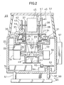
- Fig. 2 shows an embodiment of the present invention, and it is a cross-sectional elevation view when a reflection mirror is rotated.
- Fig. 3 is a control block diagram of the embodiment of the present invention.
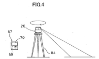
- Fig. 4 is a schematical drawing to explain the embodiment of the present invention in surveying operation.
- Fig. 5 is a control block diagram of another embodiment of the invention.
- Fig. 6 is a perspective view to explain an operation device of another embodiment of the invention.
- Fig. 7 is a partially cutaway front view of a conventional example.
- a surveying instrument 20 comprises a surveying instrument main unit 21, a leveling unit 59, and an operation device 67 removably mounted on a main unit case 22.
- a recessed portion 23 is formed on an upper surface of the main unit case 22.
- a hole 25 is formed so that a flange 24 is provided around it.
- a flanged hollow shaft 26 is mounted in the flange 24 concentrically with the hole 25, and a rotating unit 27 is rotatably engaged on the flanged hollow shaft 26 via bearings 28.
- a pattern ring 29 for an encoder is arranged perpendicularly to a rotation shaft of the rotating unit 27.
- a detector 30 is provided on an inner peripheral wall surface of the recessed portion 23 to face the pattern ring 29. The detector 30 and the pattern ring 29 make up together a horizontal angle encoder 31.
- an optical type tilt measuring unit 32 is arranged so as to oppose the pattern ring 29 on the opposite side of the flange 24 from the pattern ring 29.
- the tilt measuring unit 32 emits a tilt detecting light to the pattern ring 29 through the window hole 33 formed on the flange 24.
- the tilt measuring unit 32 has a free liquid surface in it so that a relative angle between the free liquid surface and the pattern ring 29, i.e. a tilt angle of the pattern ring 29 with respect to a horizontal line, can be detected through comparison of a reflection light from the free liquid surface with a reflection light from the pattern ring 29.
- the result of the detection at the tilt measuring unit 32 is inputted to a control unit 74 as to be described later.
- a worm wheel 34 is engaged on an upper end of the rotating unit 27.
- a horizontal rotating motor 35 is arranged on an upper surface of the main unit case 22, and a worm gear 36 mounted on an output shaft of the horizontal rotating motor 35 is engaged with the worm wheel 34.
- a pair of brackets 37 and 37 placed at positions opposite to each other are erected on an upper surface of the rotating unit 27, and a horizontal rotation shaft 38 is rotatably mounted between the brackets 37 and 37.
- a pattern ring 39 of an elevation angle encoder 41 is fixed on one end of the horizontal rotation shaft 38, and a detector 40 to match the pattern ring 39 is provided on the rotating unit 27.
- a worm wheel 42 is engaged on the other end of the horizontal rotation shaft 38, and a vertical rotating motor 43 is mounted on the upper surface of the rotating unit 27.
- a worm gear 44 engaged with an output shaft of the vertical rotating motor 43 is engaged with the worm wheel 42.
- a reflection mirror 45 is fixed on the horizontal rotation shaft 38.
- a body tube 46 is mounted on a lower end of the flanged hollow shaft 26, and the body tube 46 is coaxial with the flanged hollow shaft 26.
- an objective lens 47 a small mirror 48
- a dichroic prism 49 for reflecting a light beam of a predetermined wavelength range
- an image light receiving unit 51 As the image light receiving unit 51, a CCD sensor is used, for instance.
- a condenser lens 52 and a light emitting unit 53 for image acquisition are arranged along an optical axis of a reflection light from the small mirror 48.
- a measuring light emitting unit 54 is placed on one side opposing to the dichroic prism 49, and a measuring light detecting unit 55 is disposed on the other side opposing to the dichroic prism 49.
- the angle calculating unit 81 calculates a projecting direction of a measuring light, and the result of the calculation is inputted to the arithmetic unit 76. Also, from the tilt measuring unit 32, vertical condition of a central axis of the body tube 46, i.e. an optical axis 83, is inputted to the arithmetic unit 76.
- the image pickup unit 50 is driven via the image data control processor 78.
- a measuring light is emitted from the measuring light emitting unit 54.
- the measuring light is reflected by the dichroic prism 49 and is directed toward the reflection mirror 45.
- the distance measuring unit 56 is driven via the distance measuring data control processor 79.
- a light for image acquisition is emitted from the light emitting unit 53 for image acquisition. It is reflected by the small mirror 48 and is directed toward the reflection mirror 45.
Landscapes
- Physics & Mathematics (AREA)
- Engineering & Computer Science (AREA)
- General Physics & Mathematics (AREA)
- Radar, Positioning & Navigation (AREA)
- Remote Sensing (AREA)
- Measurement Of Optical Distance (AREA)
- Optical Radar Systems And Details Thereof (AREA)
- Length Measuring Devices By Optical Means (AREA)
Abstract
Description
Claims (8)
- A surveying instrument, comprising a surveying instrument main unit which projects a measuring light to an object to be measured and measures a position based on a reflection light from the object to be measured and an operation device which is removably attached on the surveying instrument main unit, wherein said surveying instrument main unit comprises a distance measuring unit for emitting the measuring light and for measuring a distance, an image pickup unit for acquiring an image, a reflection mirror rotatably mounted and used for directing the measuring light toward the object to be measured, for directing the reflected light from the object to be measured toward a light receiving unit, and for directing the image in a projecting direction toward said image pickup unit, a detecting means for detecting a rotating position of said reflection mirror, and a control unit for controlling at least said distance measuring unit, said image pickup unit and the rotating position of said reflection mirror, and wherein said operation device comprises a display unit for displaying the image acquired by said image pickup unit.
- A surveying instrument according to claim 1, wherein there is provided a leveling unit for adjusting tilt and for setting said surveying instrument main unit to a horizontal or a vertical position, and said operation device comprises operation switches for operating said leveling unit.
- A surveying instrument according to claim 1, wherein radio communication can be performed between said surveying instrument main unit and said operation device via transmitter/receivers, and said surveying instrument main unit can be operated from said operation device furnished separately.
- A surveying instrument, comprising a surveying instrument main unit which projects a measuring light to an object to be measured and measures a position based on a reflection light from the object to be measured and an operation device, wherein said surveying instrument main unit comprises a distance measuring unit for emitting the measuring light and for measuring a distance, an image pickup unit for acquiring an image, a reflection mirror rotatably mounted and used for directing the measuring light toward the object to be measured, for directing the reflected light from the object to be measured toward a light receiving unit, and for directing the image in a projecting direction toward said image pickup unit, a detecting means for detecting a rotating position of said reflection mirror, a control unit for controlling at least said distance measuring unit, said image pickup unit and the rotating position of said reflection mirror, and a first transmitter/receiver for receiving an operation signal for operation via said control unit and for transmitting an image data acquired by said image pickup unit, and wherein said operation device comprises a display unit and an operation unit to be operated according to programs, and a second transmitter/receiver being enable to operate said surveying instrument main unit from the operation device, enable to display the image data acquired by said image pickup unit, and capable to perform communication to and from said first transmitter/receiver.
- A surveying instrument according to claim 4, wherein said instrument comprises a leveling unit for adjusting tilt and for setting said surveying instrument main unit to a horizontal or a vertical position, and said leveling unit can be controlled by said operation device.
- A surveying instrument according to claim 4, wherein said operation device comprises an operation unit to be operated according to programs, and a display unit for displaying the image data, said programs are provided with a function to indicate operation procedure for surveying operation to said display unit, and said surveying instrument main unit is controlled according to the displayed operating procedure.
- A surveying instrument according to claim 4, wherein said first and said second transmitter/receivers transmit and receive data to and from each other, in which data for communication are established based on a common protocol.
- A surveying instrument according to claim 1 or 4, wherein a distance measuring data and an image data with respect to the object to be measured are acquired from two or more directions, and a 3-dimensional image of the object to be measured is composed based on the distance measuring data and the image data.
Applications Claiming Priority (3)
| Application Number | Priority Date | Filing Date | Title |
|---|---|---|---|
| JP2002258108A JP2004093504A (en) | 2002-09-03 | 2002-09-03 | Surveying equipment |
| JP2002258108 | 2002-09-03 | ||
| PCT/JP2003/011193 WO2004023073A1 (en) | 2002-09-03 | 2003-09-02 | Measurement device |
Publications (3)
| Publication Number | Publication Date |
|---|---|
| EP1541963A1 true EP1541963A1 (en) | 2005-06-15 |
| EP1541963A4 EP1541963A4 (en) | 2007-06-27 |
| EP1541963B1 EP1541963B1 (en) | 2011-06-15 |
Family
ID=31973014
Family Applications (1)
| Application Number | Title | Priority Date | Filing Date |
|---|---|---|---|
| EP03794179A Expired - Lifetime EP1541963B1 (en) | 2002-09-03 | 2003-09-02 | Measurement device |
Country Status (5)
| Country | Link |
|---|---|
| US (1) | US7127822B2 (en) |
| EP (1) | EP1541963B1 (en) |
| JP (1) | JP2004093504A (en) |
| CN (1) | CN1678883B (en) |
| WO (1) | WO2004023073A1 (en) |
Cited By (3)
| Publication number | Priority date | Publication date | Assignee | Title |
|---|---|---|---|---|
| WO2008089792A1 (en) * | 2007-01-26 | 2008-07-31 | Trimble Jena Gmbh | Optical instrument and method for obtaining distance and image information |
| EP1906141A3 (en) * | 2006-09-26 | 2010-01-27 | Kabushiki Kaisha Topcon | Laser scanner |
| EP1975571A3 (en) * | 2007-03-29 | 2011-11-09 | Kabushiki Kaisha TOPCON | Three-dimensional position-measuring apparatus |
Families Citing this family (68)
| Publication number | Priority date | Publication date | Assignee | Title |
|---|---|---|---|---|
| TW200530629A (en) * | 2004-02-13 | 2005-09-16 | Black & Decker Inc | Laser calibration apparatus and method |
| JP4427389B2 (en) * | 2004-06-10 | 2010-03-03 | 株式会社トプコン | Surveying instrument |
| TWI261107B (en) * | 2005-02-03 | 2006-09-01 | Asia Optical Co Inc | Laser tilt apparatus and the method thereof |
| DE202006005643U1 (en) * | 2006-03-31 | 2006-07-06 | Faro Technologies Inc., Lake Mary | Device for three-dimensional detection of a spatial area |
| JP5103004B2 (en) * | 2006-11-15 | 2012-12-19 | 株式会社トプコン | Laser surveyor |
| DE102007055439A1 (en) * | 2007-11-21 | 2009-05-28 | Hilti Aktiengesellschaft | Rotary laser with remote control |
| JP5150229B2 (en) * | 2007-12-07 | 2013-02-20 | 株式会社トプコン | Surveying system |
| JP5145029B2 (en) | 2007-12-27 | 2013-02-13 | 株式会社トプコン | Surveyor and survey correction method |
| JP5060358B2 (en) * | 2008-03-25 | 2012-10-31 | 株式会社トプコン | Surveying system |
| EP2144037A1 (en) * | 2008-07-10 | 2010-01-13 | Leica Geosystems AG | Construction laser, in particular a self-compensating rotating construction laser, and method for measuring a tilt of an axis of rotation of a construction laser |
| US8134589B2 (en) * | 2008-07-17 | 2012-03-13 | Eastman Kodak Company | Zoom by multiple image capture |
| DE102009010465B3 (en) * | 2009-02-13 | 2010-05-27 | Faro Technologies, Inc., Lake Mary | laser scanner |
| DE102009015920B4 (en) | 2009-03-25 | 2014-11-20 | Faro Technologies, Inc. | Device for optically scanning and measuring an environment |
| US9551575B2 (en) | 2009-03-25 | 2017-01-24 | Faro Technologies, Inc. | Laser scanner having a multi-color light source and real-time color receiver |
| JP2010256243A (en) * | 2009-04-27 | 2010-11-11 | Toyota Motor Corp | Scanning distance measuring device |
| DE102009035337A1 (en) | 2009-07-22 | 2011-01-27 | Faro Technologies, Inc., Lake Mary | Method for optically scanning and measuring an object |
| DE102009035336B3 (en) | 2009-07-22 | 2010-11-18 | Faro Technologies, Inc., Lake Mary | Device for optical scanning and measuring of environment, has optical measuring device for collection of ways as ensemble between different centers returning from laser scanner |
| JP2011099938A (en) * | 2009-11-04 | 2011-05-19 | Toshiba Corp | Gimbal structure including optical element |
| DE102009055989B4 (en) | 2009-11-20 | 2017-02-16 | Faro Technologies, Inc. | Device for optically scanning and measuring an environment |
| DE102009057101A1 (en) | 2009-11-20 | 2011-05-26 | Faro Technologies, Inc., Lake Mary | Device for optically scanning and measuring an environment |
| US9529083B2 (en) | 2009-11-20 | 2016-12-27 | Faro Technologies, Inc. | Three-dimensional scanner with enhanced spectroscopic energy detector |
| US9210288B2 (en) | 2009-11-20 | 2015-12-08 | Faro Technologies, Inc. | Three-dimensional scanner with dichroic beam splitters to capture a variety of signals |
| DE102009055988B3 (en) | 2009-11-20 | 2011-03-17 | Faro Technologies, Inc., Lake Mary | Device, particularly laser scanner, for optical scanning and measuring surrounding area, has light transmitter that transmits transmission light ray by rotor mirror |
| US9113023B2 (en) | 2009-11-20 | 2015-08-18 | Faro Technologies, Inc. | Three-dimensional scanner with spectroscopic energy detector |
| US9163922B2 (en) | 2010-01-20 | 2015-10-20 | Faro Technologies, Inc. | Coordinate measurement machine with distance meter and camera to determine dimensions within camera images |
| US9607239B2 (en) | 2010-01-20 | 2017-03-28 | Faro Technologies, Inc. | Articulated arm coordinate measurement machine having a 2D camera and method of obtaining 3D representations |
| DE112011100292B4 (en) | 2010-01-20 | 2016-11-24 | Faro Technologies Inc. | Display for a coordinate measuring machine |
| US9879976B2 (en) | 2010-01-20 | 2018-01-30 | Faro Technologies, Inc. | Articulated arm coordinate measurement machine that uses a 2D camera to determine 3D coordinates of smoothly continuous edge features |
| US9628775B2 (en) | 2010-01-20 | 2017-04-18 | Faro Technologies, Inc. | Articulated arm coordinate measurement machine having a 2D camera and method of obtaining 3D representations |
| JP5568363B2 (en) | 2010-04-22 | 2014-08-06 | 株式会社トプコン | Laser scanner |
| DE102010020925B4 (en) | 2010-05-10 | 2014-02-27 | Faro Technologies, Inc. | Method for optically scanning and measuring an environment |
| DE102010032725B4 (en) | 2010-07-26 | 2012-04-26 | Faro Technologies, Inc. | Device for optically scanning and measuring an environment |
| DE102010032726B3 (en) | 2010-07-26 | 2011-11-24 | Faro Technologies, Inc. | Device for optically scanning and measuring an environment |
| USD684580S1 (en) * | 2010-07-26 | 2013-06-18 | Faro Technologies, Inc. | Laser scanner |
| DE102010032723B3 (en) | 2010-07-26 | 2011-11-24 | Faro Technologies, Inc. | Device for optically scanning and measuring an environment |
| DE102010033561B3 (en) | 2010-07-29 | 2011-12-15 | Faro Technologies, Inc. | Device for optically scanning and measuring an environment |
| JP5698480B2 (en) * | 2010-09-02 | 2015-04-08 | 株式会社トプコン | Measuring method and measuring device |
| JP5459164B2 (en) * | 2010-09-27 | 2014-04-02 | 株式会社デンソーウェーブ | Laser radar equipment |
| US9168654B2 (en) | 2010-11-16 | 2015-10-27 | Faro Technologies, Inc. | Coordinate measuring machines with dual layer arm |
| DE102010061725A1 (en) * | 2010-11-22 | 2012-05-24 | Hilti Aktiengesellschaft | Rotary laser device having a tilted laser plane and method of aligning a rotary laser device |
| US8539685B2 (en) | 2011-01-20 | 2013-09-24 | Trimble Navigation Limited | Integrated surveying and leveling |
| JP5738005B2 (en) | 2011-03-01 | 2015-06-17 | 株式会社トプコン | Lightwave distance measuring device |
| DE102011085761B4 (en) * | 2011-11-04 | 2016-03-24 | Trimble Kaiserslautern Gmbh | A light beam emitting device for a measuring instrument and method for changing the optical properties of a light beam |
| EP2607843A1 (en) * | 2011-12-20 | 2013-06-26 | Leica Geosystems AG | Laser-based coordinate measuring device with a fixed-free bearing system |
| DE102012100609A1 (en) | 2012-01-25 | 2013-07-25 | Faro Technologies, Inc. | Device for optically scanning and measuring an environment |
| CN103852070B (en) * | 2012-12-06 | 2016-08-24 | 常州华达科捷光电仪器有限公司 | A kind of viewer module, a kind of form and there is the laser level of this form |
| US8997362B2 (en) | 2012-07-17 | 2015-04-07 | Faro Technologies, Inc. | Portable articulated arm coordinate measuring machine with optical communications bus |
| DE102012107544B3 (en) | 2012-08-17 | 2013-05-23 | Faro Technologies, Inc. | Optical scanning device i.e. laser scanner, for evaluating environment, has planetary gears driven by motor over vertical motor shaft and rotating measuring head relative to foot, where motor shaft is arranged coaxial to vertical axle |
| CN104603575A (en) | 2012-09-06 | 2015-05-06 | 法罗技术股份有限公司 | Laser scanner with additional sensing device |
| WO2014043461A1 (en) | 2012-09-14 | 2014-03-20 | Faro Technologies, Inc. | Laser scanner with dynamical adjustment of angular scan velocity |
| US10067231B2 (en) | 2012-10-05 | 2018-09-04 | Faro Technologies, Inc. | Registration calculation of three-dimensional scanner data performed between scans based on measurements by two-dimensional scanner |
| DE102012109481A1 (en) | 2012-10-05 | 2014-04-10 | Faro Technologies, Inc. | Device for optically scanning and measuring an environment |
| US9513107B2 (en) | 2012-10-05 | 2016-12-06 | Faro Technologies, Inc. | Registration calculation between three-dimensional (3D) scans based on two-dimensional (2D) scan data from a 3D scanner |
| JP6171502B2 (en) * | 2013-04-04 | 2017-08-02 | 船井電機株式会社 | Projector and electronic device having projector function |
| DE102013206929B4 (en) * | 2013-04-17 | 2016-02-18 | Sick Ag | Image capture system |
| EP2860546B1 (en) * | 2013-10-09 | 2019-08-07 | Hexagon Technology Center GmbH | Measuring device with a rotation mirror for optically scanning an environment |
| US10184794B2 (en) * | 2015-07-01 | 2019-01-22 | Makita Corporation | Laser marker |
| US10031329B2 (en) * | 2015-08-13 | 2018-07-24 | The Boeing Company | Off-axis optical telescope |
| DE102015122844A1 (en) | 2015-12-27 | 2017-06-29 | Faro Technologies, Inc. | 3D measuring device with battery pack |
| JP6662449B2 (en) * | 2016-03-09 | 2020-03-11 | 株式会社ニコン | Detection device, detection system, detection method, and detection program |
| JP6672109B2 (en) * | 2016-08-23 | 2020-03-25 | 株式会社トプコン | Surveying instrument communication processing system and fault handling method |
| EP3367057B1 (en) * | 2017-02-23 | 2020-08-26 | Hexagon Technology Center GmbH | Surveying instrument for scanning an object and image acquisition of the object |
| JP6867244B2 (en) * | 2017-06-28 | 2021-04-28 | 株式会社トプコン | Surveying instrument communication management system |
| EP3450913B1 (en) * | 2017-08-30 | 2021-06-09 | Hexagon Technology Center GmbH | Surveying instrument for scanning an object and for projection of information |
| JP6989354B2 (en) * | 2017-11-07 | 2022-01-05 | パイオニア株式会社 | Optical scanning device and ranging device |
| JP2019100954A (en) | 2017-12-06 | 2019-06-24 | 株式会社トプコン | Laser scanner |
| JP7194296B2 (en) * | 2017-12-06 | 2022-12-21 | 株式会社トプコン | laser scanner |
| US12253629B2 (en) | 2018-10-29 | 2025-03-18 | Nec Corporation | Sensor device and article display shelf |
Family Cites Families (21)
| Publication number | Priority date | Publication date | Assignee | Title |
|---|---|---|---|---|
| JPS61108911A (en) * | 1984-10-31 | 1986-05-27 | Asahi Optical Co Ltd | Surveying equipment having video display device |
| US4717251A (en) * | 1986-02-06 | 1988-01-05 | Cubic Corporation | Elevation measurement in high order surveying |
| JPH032513A (en) * | 1989-05-30 | 1991-01-08 | Tatsushi Miyahara | Automatic surveying equipment |
| JPH0324971A (en) | 1989-06-22 | 1991-02-01 | Nec Corp | Thermal head |
| DE4033630A1 (en) * | 1990-10-23 | 1992-04-30 | Busch Dieter & Co Prueftech | EARTH SOLDER TO DETECT VERTICAL AND LEVEL |
| JPH06186036A (en) * | 1992-12-16 | 1994-07-08 | Taisei Corp | Three-dimensional position measuring device |
| JPH0719874A (en) * | 1993-06-30 | 1995-01-20 | Topcon Corp | Surveyor and data collector |
| AUPM673394A0 (en) * | 1994-07-08 | 1994-08-04 | Connolly, Michael | Remotely operated levelling device |
| JP2919273B2 (en) * | 1994-08-02 | 1999-07-12 | 佐藤工業株式会社 | Multifunctional surveying measurement system |
| US5988862A (en) | 1996-04-24 | 1999-11-23 | Cyra Technologies, Inc. | Integrated system for quickly and accurately imaging and modeling three dimensional objects |
| JP3647608B2 (en) | 1997-06-20 | 2005-05-18 | 株式会社ソキア | Surveyor automatic tracking device |
| US6034722A (en) * | 1997-11-03 | 2000-03-07 | Trimble Navigation Limited | Remote control and viewing for a total station |
| JPH11194018A (en) | 1998-01-06 | 1999-07-21 | Nikon Corp | Subject information measurement device |
| US6480270B1 (en) | 1998-03-10 | 2002-11-12 | Riegl Laser Measurement Systems Gmbh | Method for monitoring objects or an object area |
| JP3978737B2 (en) * | 1998-05-19 | 2007-09-19 | 株式会社トプコン | Laser level device |
| JP2000221037A (en) * | 1999-01-29 | 2000-08-11 | Topcon Corp | Automatic surveying instrument and 3D measurement method |
| ATE219575T1 (en) * | 1999-08-31 | 2002-07-15 | Leica Geosystems Ag | TACHYMETER TELESCOPE |
| JP2001183108A (en) * | 1999-12-27 | 2001-07-06 | Minolta Co Ltd | Distance measuring apparatus |
| JP3799579B2 (en) * | 2001-12-18 | 2006-07-19 | 株式会社トプコン | Position measuring device |
| JP4004316B2 (en) * | 2002-03-20 | 2007-11-07 | 株式会社トプコン | Surveying device and method for acquiring image data using surveying device |
| JP2004163292A (en) * | 2002-11-13 | 2004-06-10 | Topcon Corp | Surveying equipment and electronic storage media |
-
2002
- 2002-09-03 JP JP2002258108A patent/JP2004093504A/en active Pending
-
2003
- 2003-09-02 EP EP03794179A patent/EP1541963B1/en not_active Expired - Lifetime
- 2003-09-02 WO PCT/JP2003/011193 patent/WO2004023073A1/en not_active Ceased
- 2003-09-02 US US10/501,386 patent/US7127822B2/en not_active Expired - Lifetime
- 2003-09-02 CN CN038208830A patent/CN1678883B/en not_active Expired - Fee Related
Cited By (5)
| Publication number | Priority date | Publication date | Assignee | Title |
|---|---|---|---|---|
| EP1906141A3 (en) * | 2006-09-26 | 2010-01-27 | Kabushiki Kaisha Topcon | Laser scanner |
| CN101153795B (en) * | 2006-09-26 | 2012-07-04 | 株式会社拓普康 | Laser scanner |
| WO2008089792A1 (en) * | 2007-01-26 | 2008-07-31 | Trimble Jena Gmbh | Optical instrument and method for obtaining distance and image information |
| US8368875B2 (en) | 2007-01-26 | 2013-02-05 | Trimble Jena Gmbh | Optical instrument and method for obtaining distance and image information |
| EP1975571A3 (en) * | 2007-03-29 | 2011-11-09 | Kabushiki Kaisha TOPCON | Three-dimensional position-measuring apparatus |
Also Published As
| Publication number | Publication date |
|---|---|
| WO2004023073A1 (en) | 2004-03-18 |
| CN1678883A (en) | 2005-10-05 |
| EP1541963B1 (en) | 2011-06-15 |
| US20050172503A1 (en) | 2005-08-11 |
| EP1541963A4 (en) | 2007-06-27 |
| JP2004093504A (en) | 2004-03-25 |
| US7127822B2 (en) | 2006-10-31 |
| CN1678883B (en) | 2012-02-15 |
Similar Documents
| Publication | Publication Date | Title |
|---|---|---|
| US7127822B2 (en) | Surveying instrument | |
| EP3450917B1 (en) | Surveying system | |
| US7081606B2 (en) | Position measuring system | |
| EP3457081B1 (en) | Surveying system | |
| US10823558B2 (en) | Surveying instrument | |
| JP3268608B2 (en) | Surveying equipment | |
| CA2600617C (en) | Laser scanner | |
| US9581442B2 (en) | Surveying instrument | |
| EP3771886A1 (en) | Surveying apparatus, surveying method, and surveying program | |
| EP3136050B1 (en) | Total station | |
| US10371801B2 (en) | Measuring instrument | |
| EP2788715B1 (en) | Robotic leveling | |
| US12359915B2 (en) | Surveying instrument and surveying system | |
| JP7289252B2 (en) | Scanner system and scanning method | |
| JP2013156124A (en) | Angle measurement device | |
| JP4565009B2 (en) | Surveying equipment | |
| JP2003021514A (en) | Machine height measuring device for surveying machine and surveying machine using it and machine height measuring method for surveying machine |
Legal Events
| Date | Code | Title | Description |
|---|---|---|---|
| PUAI | Public reference made under article 153(3) epc to a published international application that has entered the european phase |
Free format text: ORIGINAL CODE: 0009012 |
|
| 17P | Request for examination filed |
Effective date: 20050324 |
|
| AK | Designated contracting states |
Kind code of ref document: A1 Designated state(s): AT BE BG CH CY CZ DE DK EE ES FI FR GB GR HU IE IT LI LU MC NL PT RO SE SI SK TR |
|
| RBV | Designated contracting states (corrected) |
Designated state(s): CH DE LI SE |
|
| A4 | Supplementary search report drawn up and despatched |
Effective date: 20070525 |
|
| 17Q | First examination report despatched |
Effective date: 20070918 |
|
| GRAP | Despatch of communication of intention to grant a patent |
Free format text: ORIGINAL CODE: EPIDOSNIGR1 |
|
| GRAS | Grant fee paid |
Free format text: ORIGINAL CODE: EPIDOSNIGR3 |
|
| GRAA | (expected) grant |
Free format text: ORIGINAL CODE: 0009210 |
|
| AK | Designated contracting states |
Kind code of ref document: B1 Designated state(s): CH DE LI SE |
|
| REG | Reference to a national code |
Ref country code: CH Ref legal event code: EP Ref country code: CH Ref legal event code: NV Representative=s name: FIAMMENGHI-FIAMMENGHI |
|
| REG | Reference to a national code |
Ref country code: DE Ref legal event code: R096 Ref document number: 60337439 Country of ref document: DE Effective date: 20110721 |
|
| REG | Reference to a national code |
Ref country code: SE Ref legal event code: TRGR |
|
| PLBE | No opposition filed within time limit |
Free format text: ORIGINAL CODE: 0009261 |
|
| STAA | Information on the status of an ep patent application or granted ep patent |
Free format text: STATUS: NO OPPOSITION FILED WITHIN TIME LIMIT |
|
| 26N | No opposition filed |
Effective date: 20120316 |
|
| REG | Reference to a national code |
Ref country code: DE Ref legal event code: R097 Ref document number: 60337439 Country of ref document: DE Effective date: 20120316 |
|
| PGFP | Annual fee paid to national office [announced via postgrant information from national office to epo] |
Ref country code: SE Payment date: 20150911 Year of fee payment: 13 |
|
| PG25 | Lapsed in a contracting state [announced via postgrant information from national office to epo] |
Ref country code: SE Free format text: LAPSE BECAUSE OF NON-PAYMENT OF DUE FEES Effective date: 20160903 |
|
| REG | Reference to a national code |
Ref country code: SE Ref legal event code: EUG |
|
| PGFP | Annual fee paid to national office [announced via postgrant information from national office to epo] |
Ref country code: CH Payment date: 20170912 Year of fee payment: 15 Ref country code: DE Payment date: 20170830 Year of fee payment: 15 |
|
| REG | Reference to a national code |
Ref country code: DE Ref legal event code: R119 Ref document number: 60337439 Country of ref document: DE |
|
| REG | Reference to a national code |
Ref country code: CH Ref legal event code: PL |
|
| PG25 | Lapsed in a contracting state [announced via postgrant information from national office to epo] |
Ref country code: DE Free format text: LAPSE BECAUSE OF NON-PAYMENT OF DUE FEES Effective date: 20190402 |
|
| PG25 | Lapsed in a contracting state [announced via postgrant information from national office to epo] |
Ref country code: LI Free format text: LAPSE BECAUSE OF NON-PAYMENT OF DUE FEES Effective date: 20180930 Ref country code: CH Free format text: LAPSE BECAUSE OF NON-PAYMENT OF DUE FEES Effective date: 20180930 |