JP3978737B2 - Laser level device - Google Patents
Laser level device Download PDFInfo
- Publication number
- JP3978737B2 JP3978737B2 JP15532698A JP15532698A JP3978737B2 JP 3978737 B2 JP3978737 B2 JP 3978737B2 JP 15532698 A JP15532698 A JP 15532698A JP 15532698 A JP15532698 A JP 15532698A JP 3978737 B2 JP3978737 B2 JP 3978737B2
- Authority
- JP
- Japan
- Prior art keywords
- laser
- unit
- rotation
- axis
- horizontal axis
- Prior art date
- Legal status (The legal status is an assumption and is not a legal conclusion. Google has not performed a legal analysis and makes no representation as to the accuracy of the status listed.)
- Expired - Fee Related
Links
Images


Description
【0001】
【産業上の利用分野】
本発明は、レーザー光による測定基準線や基準平面を形成することのできるレーザー測量機に係わり、特に、水平基準線及び基準平面のみならず、水平面に対して所定の角度傾斜した基準線や基準平面を形成することのできるレーザーレベル装置に関するものである。
【0002】
【従来の技術】
従来の傾斜設定可能な回転レーザー装置には、レーザー投光部が自在に傾斜できる様に、ジンバル又は球面で支持される構造のものや、垂直軸及び水平軸上にレーザー投光部が支持されるものがある。
【0003】
ここで図10に基づいて、レーザー投光部が、球面で支持される構造のものを説明する。レーザー投光部9100は、球面で支持されており、レーザー投光部9100に設けられた回転照射部9200から、レーザー光が基準平面上に回転照射される様に構成されている。なお回転照射部9200は、モータ9250により駆動されている。
【0004】
レーザー投光部9100は、直交する2方向に伸びるアーム9300(1方向が図示せず)をモータ9350により駆動される上下機構で上下させることにより、1方向又は2方向に傾斜可能に構成されている。このレーザー投光部9100は、本体に形成された2個の傾斜センサ9410、9420とにより、整準されている。そしてレーザー投光部9100は、整準された後に所定の方向に傾斜設定される。
【0005】
この傾斜設定は、例えば、設定傾斜角度を直接、又は2個の傾斜センサ9410、9420の出力をモータのパルス数に換算し、演算された角度に基づいて、モータ9350を駆動させることにより設定することができる。なお、適宜の傾斜検出器を採用することができる。そして、レーザー投光部9100を1方向のみ傾斜させれば、所定の方向に対する傾斜面を形成し、レーザー投光部9100を2方向傾斜させれば、複合傾斜面を形成することができる。
【0006】
次に図11に基づいて、レーザー投光部9100が垂直軸及び水平軸上で支持される構成を説明する。垂直軸周りに回動する托架部9500と、托架部9500上の水平軸周りに回動するレーザー投光部9100とから構成されている。
このレーザー投光部9100上には、回転照射部9200が設けられ、基準平面上にレーザー光を回転照射することができる。そして、レーザー投光部が球面で支持される構成と同様に、適宜の整準手段により整準されている。
【0007】
レーザー投光部9100が垂直軸及び水平軸上で支持される構成では、レーザー投光部9100の回動方向が、傾斜方向と一致する様に托架部を水平軸回りに回転させ、この托架部の回転の後、レーザー投光部9100を垂直軸回りに回転させ所定角度に傾斜させることにより、傾斜設定を行う様に構成されている。
【0008】
なお複合傾斜面は、2方向の傾斜データから複合傾斜の方向と傾斜角を演算し、演算結果に基づいて決定された方向に傾斜させることにより形成することができる。
【0009】
【発明が解決しようとする課題】
しかしながら、上記従来のレーザー測量機は、傾斜設定装置の回転軸が、理想的な任意の軸を中心に回転する場合には誤差を生じさせることはないが、現実には、円滑に回転させるための軸ガタが必要であり、軸ガタの角度の換算分が傾斜誤差となるという問題点があった。
【0010】
従って、軸ガタによる傾斜誤差を小さくし、傾斜設定精度を高めることのできるレーザー測量機の出現が強く望まれていた。
【0011】
更に、球面で支持される回転レーザー装置は、傾斜を設定するための基本的構造が簡単であるため、比較的精度の高い設定が可能であるが、設定勾配に構造的限界があるため、高勾配の設定には適さないという問題点があった。
【0012】
また、垂直軸及び水平軸上で支持される回転レーザー装置は、高勾配の設定は比較的容易であるが、上述の様に、回転軸に多くの誤差が蓄積されるので、高い工作精度を要求され、コスト高となるという問題点があった。
【0013】
【課題を解決するための手段】
本発明は上記課題に鑑み案出されたもので、本体上を垂直軸周りに回動する托架部と、この托架部上にあり、前記垂直軸に直交する水平軸を回動部として回動するレーザー投光部を具備するレーザー装置本体であって、前記レーザー投光部に設けられ、前記水平軸と同軸方向にレーザー光を照射するための光源部と、前記レーザー投光部に設けられ、回動して前記水平軸に平行なレーザー平面を形成するための回動照射部と、前記托架部に設けられ、前記レーザー投光部より照射されたレーザー光を再び該レーザー投光部に反射させるための光路形成手段と、この光路形成手段に設けられた光軸の第1の補正をするための液体表面反射コンペンセータと、前記レーザー投光部に設けられ、光軸の第2の補正をするための角倍率縮小手段とを具備し、前記光路形成手段に照射されたレーザー光は、前記第1の補正の後、再び前記レーザー投光部に反射され、更に該レーザー投光部において前記第2の補正を行うことにより、前記回動照射部に向けて反射するレーザー光軸の、前記托架部と前記レーザー投光部の軸ガタによる誤差を補正することを特徴としている。
【0014】
また本発明は、前記托架部の傾きを検出するための傾斜センサを具備することもできる。
【0015】
更に本発明の液体表面反射コンペンセータは、2軸方向の補正を行う光学手段を備えることもできる。
【0016】
そして本発明は、前記液体表面反射コンペンセータと前記角倍率縮小手段とにより、前記回動照射部に向けてレーザー光軸を、水平軸と直交する方向に補正する構成にすることもできる。
【0017】
また本発明は、前記液体表面反射コンペンセータの入射と出射の光路上に、前記角倍率縮小手段が配置する構成にすることもできる。
【0018】
更に本発明の前記回動照射部は、回動を検出するための回転角検出器が設けられ、前記レーザー投光部の回動方向に往復走査のレーザー平面を形成する構成にすることもできる。
【0019】
そして本発明の托架部には、垂直軸周りの回動を検出するための第1の回転角検出器が設けられ、前記レーザー投光部には、水平軸周りの回動を検出するための第2の回転角検出部が設けられている構成にすることもできる。
【0020】
また本発明は、傾斜設定のデータと、前記第1の回転角検出部と、前記第2の回転角検出部との角度検出に基づいて、所定方向の傾斜面にレーザー光を照射する構成にすることもできる。
【0021】
【発明の実施の形態】
以上の様に構成された本発明は、托架部が本体上を垂直軸周りに回動し、レーザー装置本体は、托架部上にあり、垂直軸に直交する水平軸を回動部として回動するレーザー投光部を具備しており、レーザー投光部に設けられた光源部が、水平軸と同軸方向にレーザー光を照射し、レーザー投光部に設けられた回動照射部が、回動して水平軸に平行なレーザー平面を形成し、托架部に設けられた光路形成手段が、レーザー投光部より照射されたレーザー光を再び該レーザー投光部に反射させ、この光路形成手段に設けられた液体表面反射コンペンセータが、光軸の第1の補正を行い、レーザー投光部に設けられた角倍率縮小手段が、光軸の第2の補正を行い、光路形成手段に照射されたレーザー光は、第1の補正の後、再びレーザー投光部に反射され、更にレーザー投光部において第2の補正を行うことにより、回動照射部に向けて反射するレーザー光軸の、托架部とレーザー投光部の軸ガタによる誤差を補正することができる。
【0022】
傾斜センサが、托架部の傾きを検出することもできる。
【0023】
更に本発明の液体表面反射コンペンセータに備えた光学手段が、2軸方向の補正を行うこともできる。
【0024】
そして本発明は、液体表面反射コンペンセータと角倍率縮小手段とにより、回動照射部に向けてレーザー光軸を、水平軸と直交する方向に補正することもできる。
【0025】
また本発明は、液体表面反射コンペンセータの入射と出射の光路上に、角倍率縮小手段を配置することもできる。
【0026】
更に本発明の回動照射部に設けられた回転角検出器が回動を検出し、レーザー投光部の回動方向に往復走査のレーザー平面を形成することもできる。
【0027】
そして本発明の托架部に設けられた第1の回転角検出器が、垂直軸周りの回動を検出し、レーザー投光部に設けられた第2の回転角検出部が、水平軸周りの回動を検出することもできる。
【0028】
また本発明は、傾斜設定のデータと、第1の回転角検出部と、第2の回転角検出部との角度検出に基づいて、所定方向の傾斜面にレーザー光を照射することもできる。
【0029】
【実施例】
【0030】
本発明の実施例を図面に基づいて説明する。
【0031】
(原理)
【0032】
ここで、本発明の原理について説明する。
【0033】
「傾斜設定装置の回転軸ガタについて」
【0034】
まず、回転軸ガタについて説明する。
【0035】
図4に示す様に、X軸方向に回転軸700が設置されており、第1のベアリング710と第2のベアリング720とにより、回動自在に軸止されている。そして、この回転軸700(X軸)と直交する方向に、レーザー光が照射され、このレーザー照射光軸をZ軸とする。
【0036】
この回転軸700のガタによる光学系の傾斜誤差は、図5に示す様にXZ平面内誤差θ1と、図6に示すXY平面内誤差θ2となる。
【0037】
図5に示す様にXZ平面内誤差θ1 は、回転軸700が、原点を中心にXZ平面内で、角度θ1だけ回転した場合である。この場合には、照射されるレーザー 光は、Z軸から倒れることになる。
【0038】
レーザー装置では、Z軸の直角方向に向けて回転照射されるため、Z軸の倒れは、回転照射面の倒れとなる。例えば、水平面から傾いた平面が形成される。
【0039】
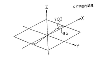
次に図6に示す様に、XY平面内誤差θ2 は、回転軸700が、原点を中心にXY平面内で、角度θ2だけ回転した場合である。
【0040】
軸ガタは、通常、XZ平面内誤差θ1 と、XY平面内誤差θ2 との誤差を有しており、XZ平面内誤差θ1 をなくすためには、XY平面内誤差θ2 もなくす必要がある。XZ平面内誤差θ1 のみを補正する構造の場合には、必ず、回転照射面の傾きとなる。
【0041】
「液体表面反射コンペンセータの原理」
【0042】
次に、液体表面反射コンペンセータ800の原理を図7に基づいて説明する。液体表面反射コンペンセータ800は、液体810と、アナモフィックプリズムビームエキスパンダー820と、ミラー830と、角倍率縮小部1400とから構成されている。
【0043】
液体810の表面は、常に水平となることから、液面がY軸を中心に角度αだけ傾いた場合には、液体810の表面を反射した後の光軸の傾き角をβ1とすれば、
【0044】
β1=2α ・・・・・・第1式
【0045】
となる。
【0046】
また、X軸を中心に角度αだけ傾いた場合には、液体810の表面を反射した後の光軸の傾き角をβ2とすれば、
【0047】
β2=cos-1(cos2θcos2α+sin2θ) ・・・・・第2式
【0048】
となり、ZY平面上で傾くことになる。ここで、θは、液体810の表面に対する液面入射角である。
【0049】
そして、液体810の屈折率をηとすれば、液体810を通過して空気側に射出された光軸は、
【0050】
β1=2αη ・・・・・・第3式
【0051】
β2=η*(cos-1(cos2θcos2α+sin2θ)) ・・・第4式
【0052】
だけ傾くことになる。
【0053】
従って、液体810への入射角が2次元で異なる場合には、入射角と射出角では、その感度が異なる。
【0054】
例えば、θ=50度、η=1.403、α=10分として、第3式、第4式に代入すれば、
【0055】
β1=2*(10分)*1.403=0.46766
【0056】
β2=1.403*(cos-1(cos2(50度)cos2(2*10分)
+sin2(50度))=0.30061
【0057】
となり、
【0058】
β1/β2=1.5557倍 ・・・・第5式
【0059】
の感度差を有している。
【0060】
更に、液面入射角θに対して、β1は、2.806倍の倍率となり、β2は、1.803倍の倍率となる。
【0061】
アナモフィックプリズムビームエキスパンダー820は、一方向のみに倍率がかかるので、第5式の感度倍率の方向に配置させ、最終的に、β1:β2=1:1となる様に設定する。即ち、この場合には、アナモフィックプリズムビームエキスパンダー820の角倍率を1/(β1/β2)=1/1.5557に設定することとなる。
【0062】
以上の様に感度倍率等を設定すれば、X、Y平面の2次元上における反射後の光軸は常に一定となり、Y軸を中心に角度αだけ傾いた場合には、アナモフィックプリズムビームエキスパンダー820を通過した後の光軸は、全方向に対して、
【0063】
2αη*(1/(β1/β2))
=2αη*(1/1.5557)=1.803α ・・・・・第6式
【0064】
だけ、もとの光軸に対して傾くことになる。
【0065】
この光束が、ミラー830により反射され、角倍率縮小部1400(倍率1.803)を通過すると、図8に示す様に、f1:f2=1.803:1により、
【0066】
1.803α*(1/1.803)=α ・・・・・第7式
【0067】
だけ傾きを補正する方向に傾くことになり、最終光軸は、常に液体表面の法線と平行となる。
【0068】
従って、装置本体の傾きと関係なく、常に鉛直方向の光軸を設定することができる。
【0069】
更に、この光軸をペンタプリズムにより90度水平方向に偏向させ、この光を回動させることにより、一定な水平面を形成することができる。
【0070】
「実施例」
【0071】
「第1実施例」
【0072】
本第1実施例のレーザー装置10000は、図1に示す様に、所定の方向に傾斜を設定することのできるレーザー装置本体1000と、このレーザー装置本体1000を水平に載置するための自動整準部2000とから構成されている。レーザー装置本体1000は、自動整準部2000に連結されており、水平方向に回転自在に取り付けられている。
【0073】
レーザー装置本体1000は、図1に示す様に、垂直軸周りに回動して傾斜方向に向けるための托架部1010と、この托架部1010上にあり、鉛直軸に交わる水平軸周りに回動して傾斜を設定するためのレーザー投光部1020とから構成されている。
【0074】
托架部1010は、モータ等の適宜の回動手段から構成された托架部駆動手段8100により回動可能に構成されている。
【0075】
更にレーザー投光部1020も、モータ等の適宜の回動手段から構成されたレーザー投光部駆動手段8200により回動可能に構成されている。
【0076】
また托架部1010は、光源部1100と、第1の反射ミラー部1371と、第2の反射ミラー部1372と、第3の反射ミラー部1373と、第4の反射ミラー部1374と、液体表面反射コンペンセータ1380と、第1の回転角検出部1700とを備えている。
【0077】
そしてレーザー投光部1020は、光源部1100と、対物レンズ1200と、ミラー1360と、角倍率縮小部1400と、回転照射部1500と、第2の回転角検出部1800とを備えている。
【0078】
光源部1100はレーザー光源であり、本実施例では、半導体レーザーが採用されているが、レーザー光を照射可能である素子であれば、何れの素子を使用することができる。
【0079】
対物レンズ1200は、光源部1100からのレーザー光を平行光線とするためのものである。本実施例では、レーザー装置本体1000の水平軸方向にレーザー光が照射される様に構成されている。
【0080】
なお、レーザー投光部1020は、光源部1100からのレーザー光の射出方向を中心軸として、回動自在に構成されている。従って、レーザー投光部1020は、水平方向と直交する面内で回転自在に取り付けられている。
【0081】
対物レンズ1200から射出されたレーザー光は、第1の反射ミラー部1371で鉛直下方に反射され、更に、第2の反射ミラー部1372で水平方向に反射されて、液体表面反射コンペンセータ1380に入射される様に構成されている。
【0082】
また、液体表面反射コンペンセータ1380から射出されたレーザー光は、第3の反射ミラー部1373で鉛直上方に反射され、更に、第4の反射ミラー部1374で、水平方向に反射されてミラー1360に入射される様に構成されている。
【0083】
ミラー1360の前後には、角倍率縮小部1400が配置されている。角倍率縮小部1400は、ミラー1360の後に配置する構成にすることもできる。図1の場合では、コンパクトに構成するためミラー1360を介して構成されている。
【0084】
そしてミラー1360に入射されたレーザー光は、角倍率縮小部1400で補正され、鉛直上方に反射される様に構成されている。
【0085】
液面が水平になることを利用した液体表面反射コンペンセータ1380と、角倍率縮小部1400とは、常に鉛直方向の光軸を形成するためのものである。
【0086】
この液体表面反射コンペンセータ1380の原理は、上述の「液体表面反射コンペンセータの原理」に記載した通りである。
【0087】
本第1実施例の液体表面反射コンペンセータ1380は、液体1381と、アナモフィックプリズム1382、1382とを備えている。液体1381は、ジメチルシリコンオイルが採用されているが、何れの液体を使用してもよい。アナモフィックプリズム1382は、Yz方向に1/1.5557倍の倍率を有し、Yx方向には、1倍の倍率となる。
【0088】
そして、液体表面反射コンペンセータ1380全体では、Yz方向に2.806倍の倍率を有し、Yx方向には、1.803倍の倍率を有している。
【0089】
また、第4の反射ミラー部1374とミラー1360との間と、ミラー1360の鉛直上方には、角倍率縮小部1400が配置されている。
【0090】
本第1実施例の角倍率縮小部1400は、f1:f2=1.803:1となっており、XZ平面内誤差θ1を1/1.803とするものである。なお、液体表面反射コンペンセータ1380の倍率に合わせて、1/Xとすることができる。
【0091】
回転照射部1500は、レーザー投光部1020に設けられ、傾斜設定した基準平面上にレーザー光を回転照射させるためのものである。この回転照射部1500には、ペンタプリズム1510が固定されており、回転照射部駆動手段8300により回転可能に構成されている。レーザー光偏角部1300により鉛直上方に反射されたレーザー光は、角倍率縮小部1400を通過した後、ペンタプリズム1510に入射される。
【0092】
ペンタプリズム1510に入射されたレーザー光は、反射されて90度偏向されると共に、回転ヘッド1500の回転に伴って、平面方向に回転照射される様に構成されている。従って、任意な方向の傾斜した平面内に、レーザー光を照射してレーザー基準面を形成することができる。
【0093】
傾斜センサ1600は、第1の傾斜センサ1610と第2の傾斜センサ1620とから構成されており、レーザー装置本体1000の傾きを検出することができる。この傾斜センサ1600は、傾きを検出することができるものであれば、何れのセンサを採用することができる。本実施例では、気泡管が採用されており、第1の傾斜センサ1610と第2の傾斜センサ1620により、レーザー装置本体1000の水平に対する傾きを検出することができる。
【0094】
傾きを検出する傾斜センサ1600として例えば、図2に示す様な気泡管を用いたセンサが利用できる。このセンサは、気泡管1650の上面に2つの電極1651、1652、下面に電極1653を配置し、気泡1650aが気泡管の傾きに従って移動し、電極1651と電極1653間及び電極1652と電極1653間の静電容量C1、C2 の変化に変換し、これを検出することにより、気泡 管1650の傾きθを求めるものである。
【0095】
第1の回転角検出部1700は、托架部1010の垂直軸周り(水平方向)の回転角度を検出すると共に、傾斜方向の設定を行うためのものである。本実施例ではローター1710が、托架部1010に取り付けられており、このローター1710と対向する位置にステータ1720を配置し、ローター1710とステータ1720との間の回転角を検出する様に構成されている。第1の回転角検出部1700は、托架部1010の水平方向の回転角度を検出することが可能なものであれば、何れのセンサを使用することができる。
【0096】
第2の回転角検出部1800は、レーザー投光部1020に設けられ、水平軸周りの回転角度を検出するためのものである。本実施例ではローター1810が、レーザー投光部1020に取り付けられており、このローター1810と対向する位置にステータ1820を配置し、ローター1810とステータ1820との間の回転角を検出する様に構成されている。第2の回転角検出部1800は、レーザー投光部1020の水平軸周りの回転角度を検出することが可能なものであれば、何れのセンサを使用することができる。
【0097】
次に、図3(a)に基づいて本実施例の電気的構成を説明する。
【0098】
本実施例は、托架部駆動手段8100と、この托架部駆動手段8100を制御駆動するための托架部駆動回路8110と、レーザー投光部駆動手段8200と、このレーザー投光部駆動手段8200を駆動するためのレーザー投光部駆動回路8210と、回転照射部駆動手段8300と、この回転照射部駆動手段8300を駆動するための回転照射部駆動回路8310と、第1の回転角検出部1700と、この第1の回転角検出部1700からの信号を処理するための第1の信号処理回路1730と、第2の回転角検出部1800と、この第2の回転角検出部1800からの信号を処理するための第2の信号処理回路1830と、制御手段6000と、設定手段8500と、自動整準部2000とから構成されている。
【0099】
第1の回転角検出部1700と第2の回転角検出部1800の検出信号に基づき、制御手段6000が、所定の方向にレーザー基準面を作成させる駆動量を演算し、托架部駆動回路8110と、レーザー投光部駆動回路8210と、回転照射部駆動回路8310とを介して、托架部駆動手段8100とレーザー投光部駆動手段8200と回転照射部駆動手段8300とを駆動する様に構成されている。
【0100】
なお、設定手段8500が、所定のレーザー基準面を得るためのデータを設定する様になっている。例えば設定手段8500が、2方向の複合傾斜を設定すれば、制御手段6000が設定データに基づいた演算を行い、所定のレーザー基準面を形成させる。
【0101】
そして設定手段8500は、基準データ設定手段に該当するものである。
【0102】
更に、回転照射部駆動手段8300が第1の駆動手段に該当し、托架部駆動手段8100が第2の駆動手段に該当し、レーザー投光部駆動手段8200が第3の駆動手段に該当するものである。
【0103】
また、自動整準部2000は、第1の傾斜センサ1610と第2の傾斜センサ1620のデータに基づき、制御手段6000が、托架部1010の回転中心を鉛直方向と一致させる様にするものである。詳細は以下に説明する。
【0104】
以上の様に構成されたレーザー装置本体1000は、水平又は鉛直方向にレーザー光線を走査させるものであり、水平出し、心出し、鉛直出し等を行うことができる。即ち、水平面内に走査されるレーザー光線を、測量対象上で検出し、その到達高さから水準測量等を行ったり、鉛直方向にレーザー光線を視光させて、地上の基準点を移行設定させることができる。
【0105】
自動整準部2000は、整準台2100と底板2200とからなっており、整準台2100は、3個の整準ネジ2300、2300、2300により上下動自在に支持されている。
【0106】
次に、自動整準部2000の電気系統を図3(b)に基づいて説明すると、第1の傾斜センサ1610と、第2の傾斜センサ1620と、制御手段6000と、第1のモータ駆動手段7100と、第2のモータ駆動手段7200と、第3のモータ駆動手段7300と、第1のモータ4310と、第2のモータ4320と、第3のモータ4330とからなっている。
【0107】
第1の傾斜センサ1610と第2の傾斜センサ1620とは、直交する2軸方向の傾きを検出する様に設定され、レーザー装置本体1000の傾きを検出するものである。
【0108】
第2の傾斜センサ1620と第1の傾斜センサ1610との検出により、托架部の回転中心を垂直に設定するものである。
【0109】
制御手段6000は、第1の傾斜センサ1610と第2の傾斜センサ1620の出力信号に基づき、整準台2100を基準面に設定するために必要な整準ネジ2300、2300、2300の変位量を演算するものである。即ち、第1の傾斜センサ1610と第2の傾斜センサ1620とが検出した傾き角が、両方とも0度となる様な3個の整準ネジ2300、2300、2300の移動量をそれぞれ計算するものである。
【0110】
制御手段6000は、それぞれの整準ネジ2300、2300、2300の移動量に相当する制御信号を、対応する第1、2、3のモータ駆動手段7100、7200、7300に送出する。第1、2、3のモータ駆動手段7100、7200、7300は、図示せぬコネクタを介して制御手段6000からの制御信号に基ずき、モータ4310、4320、4330を回動させるための電力を発生させる様になっている。
【0111】
モータ4310、4320、4330は、モータ駆動手段7100、7200、7300から供給された電力により整準ネジ2300、2300、2300を回動させ、整準台2100の傾きを修正する。そして、第1の傾斜センサ1610と第2の傾斜センサ1620は、再び整準台2100の傾きを検出し、フィードバック制御を行うことにより、レーザー装置本体1000の鉛直軸を正確に鉛直に整準(基準面に設定)させることができる。なお、任意の2個の整準ネジのみを駆動する様に構成しても、整準が可能である。
【0112】
以上の様に構成された本実施例は、自動整準部2000が採用されているので、観測者が平盤水準器を視認しながら、整準ネジ230、230、230を手動で操作することなく、レーザー装置本体1000の鉛直軸の整準を自動的に行うことができる。
【0113】
そして托架部1010で支持するレーザー投光部1020の回転軸の軸ガタ、XZ平面内の角度θ1 、XY平面内のθ2 は、液体表面反射コンペンセータ1380と角倍率縮小部1400により、補正相殺され、誤差のない所定の基準平面を作成することができる。
【0114】
なお、液体表面反射コンペンセータ1380と角倍率縮小部1400との組み合わせによる補正系は、それ自身でレーザー装置本体1000の傾きも補正することが可能である。それ程大きくない傾きを補正するのみであれば、自動整準部2000を使用しない構成にすることもできる。
【0115】
「第2実施例」
【0116】
本第2実施例のレーザー装置20000は、図9に示す様に、所定の方向に傾斜を設定することのできるレーザー装置本体1001と、このレーザー装置本体1001を水平に載置するための自動整準部2000とから構成されている。レーザー装置本体1001は、自動整準部2000に対して連結されており、水平方向に回転自在に取り付けられている。
【0117】
またレーザー装置本体1001は、光源部1100と、対物レンズ1200と、ミラー1360と、第1の反射ミラー部1371と、第2の反射ミラー部1372と、第3の反射ミラー部1373と、第4の反射ミラー部1374と、液体表面反射コンペンセータ1380と、第1の角倍率変換部1391と、第2の角倍率変換部1392と、角倍率縮小部1400と、回転照射部1500と、傾斜センサ1600と、第1の回転角検出部1700と、第2の回転角検出部1800とが備えられている。
【0118】
対物レンズ1200から射出されたレーザー光は、第1の反射ミラー部1371で鉛直下方に反射され、第1の角倍率変換部1391を通過した後、更に、第2の反射ミラー部1372で水平方向に反射されて、液体表面反射コンペンセータ1380に入射される様に構成されている。
【0119】
また、液体表面反射コンペンセータ1380から射出されたレーザー光は、第3の反射ミラー部1373で鉛直上方に反射され、第2の角倍率変換部1392を通過した後、更に、第4の反射ミラー部1374で、水平方向に反射されてミラー1360に入射される様に構成されている。
【0120】
第1の角倍率変換部1391と、第2の角倍率変換部1392とは、共に、f3:f4=1.109:1の倍率を有している。
【0121】
そして、第4の反射ミラー部1374とミラー1360との間と、ミラー1360の鉛直上方には、角倍率縮小部1400が配置されており、この倍率は、第1の角倍率変換部1391と第2の角倍率変換部1392とが、光路中に挿入されているので、f1:f2=2:1となっている。
【0122】
第2実施例のその他の構成、効果、作用等は、第1実施例と同様であるから、説明を省略する。
【0123】
【効果】
以上の様に構成された本発明は、本体上を垂直軸周りに回動する托架部と、この托架部上にあり、前記垂直軸に直交する水平軸を回動部として回動するレーザー投光部を具備するレーザー装置本体であって、前記レーザー投光部に設けられ、前記水平軸と同軸方向にレーザー光を照射するための光源部と、前記レーザー投光部に設けられ、回動して前記水平軸に平行なレーザー平面を形成するための回動照射部と、前記托架部に設けられ、前記レーザー投光部より照射されたレーザー光を再び該レーザー投光部に反射させるための光路形成手段と、この光路形成手段に設けられた光軸の第1の補正をするための液体表面反射コンペンセータと、前記レーザー投光部に設けられ、光軸の第2の補正をするための角倍率縮小手段とを具備し、前記光路形成手段に照射されたレーザー光は、前記第1の補正の後、再び前記レーザー投光部に反射され、更に該レーザー投光部において前記第2の補正を行うことにより、前記回動照射部に向けて反射するレーザー光軸の、前記托架部と前記レーザー投光部の軸ガタによる誤差を補正するので、球面で支持されるタイプの回転レーザー装置でも、高勾配の設定が可能であり、垂直軸及び水平軸上で支持されるタイプの回転レーザー装置でも、回転軸に多くの誤差が蓄積されることなく、コスト安で高精度のレーザー装置を提供できるという卓越した効果がある。
【0124】
【図面の簡単な説明】
【図1】本発明の第1実施例であるレーザー装置1000を説明する図である。
【図2】傾斜センサ1600を説明する図である。
【図3(a)】本実施例の電気的構成を説明する図である。
【図3(b)】自動整準部2000の電気系統を説明する図である。
【図4】傾斜設定装置の回転軸ガタについて説明する図である。
【図5】XZ平面内誤差θ1を説明する図である。
【図6】XY平面内誤差θ2を説明する図である。
【図7】原理を説明する図である。
【図8】原理を説明する図である。
【図9】本発明の第2実施例であるレーザー装置1001を説明する図である。
【図10】従来技術を説明する図である。
【図11】従来技術を説明する図である。
【符号の説明】
10000 第1実施例のレーザー装置
20000 第2実施例のレーザー装置
1000 第1実施例のレーザー装置本体
1001 第2実施例のレーザー装置本体
1010 托架部
1020 レーザー投光部
1100 光源部
1200 対物レンズ
1300 レーザー光偏角部
1360 ミラー
1371 第1の反射ミラー部
1372 第2の反射ミラー部
1373 第3の反射ミラー部
1374 第4の反射ミラー部
1375 第5の反射ミラー部
1376 第6の反射ミラー部
1377 第7の反射ミラー部
1378 第8の反射ミラー部
1380 液体表面反射コンペンセータ
1381 液体
1382 アナモフィックプリズム
1391 第1の角倍率変換部
1392 第2の角倍率変換部
1400 角倍率縮小部
1500 回転ヘッド
1510 ペンタプリズム
1600 傾斜センサ
1610 第1の傾斜センサ
1620 第2の傾斜センサ
1700 第1の回転角検出部
1710 ローター
1720 ステータ
1730 第1の信号処理回路
1800 第2の回転角検出部
1810 ローター
1820 ステータ
1830 第2の信号処理回路
2000 自動整準部
2100 整準台
2300 整準ネジ
4000 駆動手段
6000 制御手段
8100 托架部駆動手段
8110 托架部駆動回路
8200 レーザー投光部駆動手段
8210 レーザー投光部駆動回路
8300 回転照射部駆動手段
8310 回転照射部駆動回路
8500 設定手段[0001]
[Industrial application fields]
The present invention relates to a laser surveying instrument capable of forming a measurement reference line and a reference plane by laser light, and more particularly, a reference line and a reference inclined at a predetermined angle with respect to a horizontal plane as well as a horizontal reference line and a reference plane. The present invention relates to a laser level device capable of forming a plane.
[0002]
[Prior art]
In conventional rotary laser devices that can be tilted, the laser projector is supported by a gimbal or a spherical surface so that the laser projector can be tilted freely, and the laser projector is supported on the vertical and horizontal axes. There is something.
[0003]
Here, based on FIG. 10, the thing of the structure where a laser projection part is supported by a spherical surface is demonstrated. The
[0004]
The
[0005]
This tilt setting is set, for example, by setting the tilt angle directly or by converting the outputs of the two
[0006]
Next, a configuration in which the
A
[0007]
In the configuration in which the
[0008]
The compound inclined surface can be formed by calculating the compound inclination direction and the inclination angle from the two directions of inclination data and inclining in the direction determined based on the calculation result.
[0009]
[Problems to be solved by the invention]
However, the conventional laser surveying instrument does not cause an error when the rotation axis of the tilt setting device rotates around an ideal arbitrary axis, but in reality, it rotates smoothly. There is a problem that the amount of shaft backlash is necessary, and the converted angle of the shaft backlash results in a tilt error.
[0010]
Accordingly, there has been a strong demand for the appearance of a laser surveying instrument that can reduce the tilt error due to axial backlash and increase the tilt setting accuracy.
[0011]
Furthermore, the rotating laser device supported by a spherical surface has a simple basic structure for setting the inclination, so that it can be set with relatively high accuracy. There was a problem that it was not suitable for setting the gradient.
[0012]
In addition, a rotary laser device supported on the vertical axis and the horizontal axis is relatively easy to set a high gradient. However, as described above, a lot of errors are accumulated on the rotary axis, so that high working accuracy is achieved. There was a problem that it was required and the cost was high.
[0013]
[Means for Solving the Problems]
The present invention has been devised in view of the above problems, and a rack part that rotates around a vertical axis on the main body, and a horizontal axis that is on the rack part and is orthogonal to the vertical axis is a rotary part. A laser apparatus main body comprising a rotating laser projector, the light source being provided in the laser projector and irradiating laser light in a direction coaxial with the horizontal axis, and the laser projector A rotation irradiating unit for rotating to form a laser plane parallel to the horizontal axis, and a laser beam provided on the frame and irradiated from the laser projecting unit again. An optical path forming means for reflecting on the optical section, a liquid surface reflecting compensator for performing a first correction of the optical axis provided on the optical path forming means, and a laser projecting section provided on the laser projection section. Angular magnification reduction means for correcting 2 Then, after the first correction, the laser light irradiated to the optical path forming means is reflected again by the laser projector, and further, the second correction is performed in the laser projector, It is characterized in that an error caused by axial backlash between the frame part and the laser light projecting part of the laser optical axis reflected toward the rotating irradiation part is corrected.
[0014]
The present invention may also include an inclination sensor for detecting the inclination of the rack part.
[0015]
Furthermore, the liquid surface reflective compensator of the present invention can also include optical means for performing biaxial correction.
[0016]
The present invention can also be configured such that the laser optical axis is corrected in a direction perpendicular to the horizontal axis toward the rotational irradiation unit by the liquid surface reflection compensator and the angular magnification reduction means.
[0017]
The present invention may also be configured such that the angular magnification reduction means is disposed on the incident and outgoing optical paths of the liquid surface reflecting compensator.
[0018]
Further, the rotation irradiation unit of the present invention may be provided with a rotation angle detector for detecting rotation, and a laser plane for reciprocal scanning may be formed in the rotation direction of the laser projection unit. .
[0019]
The rack portion of the present invention is provided with a first rotation angle detector for detecting the rotation about the vertical axis, and the laser projector is for detecting the rotation about the horizontal axis. It is also possible to adopt a configuration in which the second rotation angle detector is provided.
[0020]
Further, the present invention is configured to irradiate laser light on a tilted surface in a predetermined direction based on tilt setting data, and angle detection of the first rotation angle detection unit and the second rotation angle detection unit. You can also
[0021]
DETAILED DESCRIPTION OF THE INVENTION
In the present invention configured as described above, the rack part rotates on the main body around the vertical axis, and the laser apparatus main body is on the frame part, and the horizontal axis orthogonal to the vertical axis is used as the rotation part. A rotating laser projecting unit is provided, the light source unit provided in the laser projecting unit irradiates laser light in the direction coaxial with the horizontal axis, and the rotating projecting unit provided in the laser projecting unit The laser beam is rotated to form a laser plane parallel to the horizontal axis, and the optical path forming means provided in the frame part reflects the laser beam emitted from the laser projector unit again to the laser projector unit, The liquid surface reflection compensator provided in the optical path forming unit performs the first correction of the optical axis, and the angular magnification reduction unit provided in the laser projection unit performs the second correction of the optical axis, and the optical path forming unit. After the first correction, the laser light applied to the Further, by performing the second correction in the laser projection unit, it is possible to correct an error caused by the backlash of the mounting unit and the laser projection unit of the laser optical axis reflected toward the rotation irradiation unit. .
[0022]
The inclination sensor can also detect the inclination of the rack part.
[0023]
Furthermore, the optical means provided in the liquid surface reflective compensator of the present invention can also perform biaxial correction.
[0024]
And this invention can also correct | amend a laser optical axis to the direction orthogonal to a horizontal axis toward a rotation irradiation part with a liquid surface reflection compensator and an angular magnification reduction means.
[0025]
In the present invention, the angular magnification reduction means can be arranged on the incident and outgoing optical paths of the liquid surface reflecting compensator.
[0026]
Furthermore, the rotation angle detector provided in the rotation irradiation unit of the present invention can detect the rotation and form a laser plane for reciprocal scanning in the rotation direction of the laser projection unit.
[0027]
And the 1st rotation angle detector provided in the rack part of this invention detects rotation around a vertical axis, and the 2nd rotation angle detection part provided in the laser projection part is a horizontal axis rotation. Can also be detected.
[0028]
The present invention can also irradiate the inclined surface in the predetermined direction with the laser beam based on the tilt setting data, and the angle detection of the first rotation angle detection unit and the second rotation angle detection unit.
[0029]
【Example】
[0030]
Embodiments of the present invention will be described with reference to the drawings.
[0031]
(principle)
[0032]
Here, the principle of the present invention will be described.
[0033]
“Rotation axis play of tilt setting device”
[0034]
First, the rotation shaft backlash will be described.
[0035]
As shown in FIG. 4, a
[0036]
The tilt error of the optical system due to the backlash of the
[0037]
As shown in FIG. 5, the XZ-plane error θ 1 is a case where the
[0038]
In the laser apparatus, rotation irradiation is performed in a direction perpendicular to the Z axis, so that the tilting of the Z axis causes the rotation irradiation surface to tilt. For example, a plane inclined from a horizontal plane is formed.
[0039]
Next, as shown in FIG. 6, the XY in-plane error θ 2 is a case where the
[0040]
The axial backlash usually has an error of XZ in-plane error θ 1 and XY in-plane error θ 2. To eliminate XZ in-plane error θ 1 , it is necessary to eliminate XY in-plane error θ 2. There is. In the case of a structure in which only the XZ in-plane error θ 1 is corrected, the rotation irradiation surface is always inclined.
[0041]
"Principle of liquid surface reflection compensator"
[0042]
Next, the principle of the liquid surface
[0043]
Since the surface of the liquid 810 is always horizontal, if the liquid surface is inclined by an angle α about the Y axis, the inclination angle of the optical axis after reflecting the surface of the liquid 810 is β 1. ,
[0044]
β 1 = 2α ······· 1 formula
It becomes.
[0046]
Further, if the optical axis is inclined by an angle α around the X axis, the inclination angle of the optical axis after reflecting the surface of the liquid 810 is β 2 .
[0047]
β 2 = cos -1 (cos 2 θcos2α + sin 2 θ) ····· second equation [0048]
And tilt on the ZY plane. Here, θ is a liquid surface incident angle with respect to the surface of the liquid 810.
[0049]
If the refractive index of the liquid 810 is η, the optical axis emitted through the liquid 810 to the air side is
[0050]
β 1 = 2αη (3)
β 2 = η * (cos -1 (cos 2 θcos2α + sin 2 θ)) ··· fourth equation [0052]
Will just lean.
[0053]
Therefore, when the incident angle to the liquid 810 is two-dimensionally different, the sensitivity differs between the incident angle and the exit angle.
[0054]
For example, if θ = 50 degrees, η = 1.403, α = 10 minutes, and substituting into the third and fourth equations,
[0055]
β 1 = 2 * (10 minutes) * 1.43 = 0.46766
[0056]
β 2 = 1.403 * (cos −1 (cos 2 (50 degrees) cos 2 (2 * 10 minutes)
+ Sin 2 (50 degrees)) = 0.30061
[0057]
And
[0058]
β 1 / β 2 = 1.5557 times .... Formula 5
Sensitivity difference.
[0060]
Furthermore, with respect to the liquid surface incident angle θ, β 1 has a magnification of 2.806 times, and β 2 has a magnification of 1.803 times.
[0061]
Since the anamorphic
[0062]
If the sensitivity magnification and the like are set as described above, the optical axis after reflection on the two dimensions of the X and Y planes is always constant, and when tilted by an angle α around the Y axis, the anamorphic
[0063]
2αη * (1 / (β 1 / β 2 ))
= 2αη * (1 / 1.5557) = 1.803α Expression 6
Only tilted with respect to the original optical axis.
[0065]
When this light beam is reflected by the
[0066]
1.803α * (1 / 1.803) =
The final optical axis is always parallel to the normal of the liquid surface.
[0068]
Therefore, the optical axis in the vertical direction can always be set regardless of the inclination of the apparatus main body.
[0069]
Furthermore, a certain horizontal plane can be formed by deflecting the optical axis 90 degrees horizontally by a pentaprism and rotating the light.
[0070]
"Example"
[0071]
“First Example”
[0072]
As shown in FIG. 1, the
[0073]
As shown in FIG. 1, the laser apparatus
[0074]
The
[0075]
Further, the
[0076]
The
[0077]
The
[0078]
The
[0079]
The
[0080]
Note that the
[0081]
The laser light emitted from the
[0082]
Further, the laser light emitted from the liquid
[0083]
An angular
[0084]
The laser light incident on the
[0085]
The liquid
[0086]
The principle of the liquid
[0087]
The liquid surface
[0088]
The entire liquid surface
[0089]
Further, an angular
[0090]
The angular
[0091]
The
[0092]
The laser light incident on the
[0093]
The tilt sensor 1600 includes a first tilt sensor 1610 and a
[0094]
As the inclination sensor 1600 for detecting the inclination, for example, a sensor using a bubble tube as shown in FIG. 2 can be used. This sensor has two
[0095]
The first rotation
[0096]
The second rotation
[0097]
Next, the electrical configuration of the present embodiment will be described with reference to FIG.
[0098]
In the present embodiment, a
[0099]
Based on the detection signals of the first rotation
[0100]
Note that the setting means 8500 sets data for obtaining a predetermined laser reference plane. For example, when the
[0101]
The
[0102]
Further, the rotation irradiation
[0103]
The
[0104]
The laser device
[0105]
The
[0106]
Next, the electric system of the
[0107]
The first tilt sensor 1610 and the
[0108]
By detecting the
[0109]
Based on the output signals of the first tilt sensor 1610 and the
[0110]
The control means 6000 sends control signals corresponding to the movement amounts of the leveling screws 2300, 2300, 2300 to the corresponding first, second, and third motor driving means 7100, 7200, 7300. The first, second, and third motor driving means 7100, 7200, and 7300 use electric power for rotating the
[0111]
The
[0112]
In the present embodiment configured as described above, the
[0113]
Then, the backlash of the rotation axis of the
[0114]
Note that the correction system using the combination of the liquid
[0115]
"Second Example"
[0116]
As shown in FIG. 9, the
[0117]
The laser device
[0118]
The laser light emitted from the
[0119]
Further, the laser light emitted from the liquid
[0120]
Both the first angular
[0121]
An angular
[0122]
Other configurations, effects, operations, and the like of the second embodiment are the same as those of the first embodiment, and thus description thereof is omitted.
[0123]
【effect】
The present invention configured as described above has a rack part that rotates about the vertical axis on the main body, and rotates on the horizontal part perpendicular to the vertical axis that is on the frame part and that rotates on the vertical part. A laser apparatus main body comprising a laser projection unit, provided in the laser projection unit, provided in the laser projection unit, a light source unit for irradiating laser light in a direction coaxial with the horizontal axis, A rotating irradiation unit for rotating to form a laser plane parallel to the horizontal axis, and a laser beam provided from the laser projection unit to the laser projection unit again. An optical path forming means for reflecting, a liquid surface reflecting compensator for performing a first correction of the optical axis provided in the optical path forming means, and a second correction of the optical axis provided in the laser projector. An angular magnification reduction means for The laser light applied to the path forming means is reflected again by the laser projector after the first correction, and the rotation correction is performed by performing the second correction in the laser projector. The error of the laser beam axis reflected toward the part due to the axial backlash between the stand and the laser projection part is corrected, so a high gradient can be set even with a rotating laser device supported by a spherical surface. Even with a rotary laser device of a type supported on a vertical axis and a horizontal axis, there is an excellent effect that a high-precision laser device can be provided at low cost without accumulating many errors on the rotary shaft.
[0124]
[Brief description of the drawings]
FIG. 1 is a diagram illustrating a
FIG. 2 is a diagram illustrating a tilt sensor 1600. FIG.
FIG. 3A is a diagram illustrating the electrical configuration of the present embodiment.
FIG. 3B is a diagram illustrating an electrical system of the
FIG. 4 is a diagram illustrating a rotation shaft backlash of the tilt setting device.
FIG. 5 is a diagram for explaining an XZ in-plane error θ 1 ;
6 is a diagram illustrating an XY plane error theta 2.
FIG. 7 is a diagram illustrating the principle.
FIG. 8 is a diagram illustrating the principle.
FIG. 9 is a diagram for explaining a
FIG. 10 is a diagram illustrating a conventional technique.
FIG. 11 is a diagram illustrating a conventional technique.
[Explanation of symbols]
10000
Claims (8)
Priority Applications (1)
| Application Number | Priority Date | Filing Date | Title |
|---|---|---|---|
| JP15532698A JP3978737B2 (en) | 1998-05-19 | 1998-05-19 | Laser level device |
Applications Claiming Priority (1)
| Application Number | Priority Date | Filing Date | Title |
|---|---|---|---|
| JP15532698A JP3978737B2 (en) | 1998-05-19 | 1998-05-19 | Laser level device |
Publications (2)
| Publication Number | Publication Date |
|---|---|
| JPH11325891A JPH11325891A (en) | 1999-11-26 |
| JP3978737B2 true JP3978737B2 (en) | 2007-09-19 |
Family
ID=15603454
Family Applications (1)
| Application Number | Title | Priority Date | Filing Date |
|---|---|---|---|
| JP15532698A Expired - Fee Related JP3978737B2 (en) | 1998-05-19 | 1998-05-19 | Laser level device |
Country Status (1)
| Country | Link |
|---|---|
| JP (1) | JP3978737B2 (en) |
Families Citing this family (5)
| Publication number | Priority date | Publication date | Assignee | Title |
|---|---|---|---|---|
| JP2004093504A (en) | 2002-09-03 | 2004-03-25 | Topcon Corp | Surveying device |
| JP4565009B2 (en) * | 2008-02-01 | 2010-10-20 | 株式会社トプコン | Surveying equipment |
| JP5060358B2 (en) | 2008-03-25 | 2012-10-31 | 株式会社トプコン | Surveying system |
| JP5550855B2 (en) * | 2009-06-12 | 2014-07-16 | 株式会社トプコン | Rotating laser emission device |
| CN108072358B (en) * | 2018-02-07 | 2024-01-09 | 东莞欧达电子有限公司 | Laser level tester without physical teaching and assembling and processing method thereof |
-
1998
- 1998-05-19 JP JP15532698A patent/JP3978737B2/en not_active Expired - Fee Related
Also Published As
| Publication number | Publication date |
|---|---|
| JPH11325891A (en) | 1999-11-26 |
Similar Documents
| Publication | Publication Date | Title |
|---|---|---|
| EP2056066B1 (en) | Surveying Instrument | |
| US6688011B2 (en) | Modular laser system for level determination | |
| US7454842B2 (en) | Laser surveying apparatus | |
| US7433028B2 (en) | Laser surveying instrument | |
| JPH10221073A (en) | Position-detecting survey machine | |
| JP3799579B2 (en) | Position measuring device | |
| CN1829899A (en) | Method for checking or calibrating the angle-dependent alignment of a high-precision test piece | |
| JP3706203B2 (en) | Rotating laser device | |
| JP3937268B2 (en) | Laser equipment | |
| US6160616A (en) | Laser system | |
| JP3978737B2 (en) | Laser level device | |
| JP4317639B2 (en) | Laser surveyor | |
| JP4035800B2 (en) | Laser equipment | |
| US6151106A (en) | Laser irradiation system | |
| JP3937261B2 (en) | Laser equipment | |
| JP2696240B2 (en) | Surveying equipment | |
| JP7324097B2 (en) | Three-dimensional surveying device, three-dimensional surveying method and three-dimensional surveying program | |
| JP3619370B2 (en) | Laser surveying equipment | |
| JP3623885B2 (en) | Laser surveying equipment | |
| JP4824212B2 (en) | Laser irradiation device | |
| JP6670355B2 (en) | Tilt detecting device and rotating laser device | |
| KR100860992B1 (en) | Angle calibrating apparatus and method of evaluating system for driving characteristic of scanner | |
| SU935705A1 (en) | Device for setting reference light surface | |
| JP2001183134A (en) | Inclination controller and inclination controlling method | |
| JP2550138Y2 (en) | Screen installation level line creation device |
Legal Events
| Date | Code | Title | Description |
|---|---|---|---|
| A621 | Written request for application examination |
Free format text: JAPANESE INTERMEDIATE CODE: A621 Effective date: 20050414 |
|
| A131 | Notification of reasons for refusal |
Free format text: JAPANESE INTERMEDIATE CODE: A131 Effective date: 20061212 |
|
| A521 | Written amendment |
Free format text: JAPANESE INTERMEDIATE CODE: A523 Effective date: 20070208 |
|
| A131 | Notification of reasons for refusal |
Free format text: JAPANESE INTERMEDIATE CODE: A131 Effective date: 20070313 |
|
| A521 | Written amendment |
Free format text: JAPANESE INTERMEDIATE CODE: A523 Effective date: 20070509 |
|
| TRDD | Decision of grant or rejection written | ||
| A01 | Written decision to grant a patent or to grant a registration (utility model) |
Free format text: JAPANESE INTERMEDIATE CODE: A01 Effective date: 20070612 |
|
| A61 | First payment of annual fees (during grant procedure) |
Free format text: JAPANESE INTERMEDIATE CODE: A61 Effective date: 20070615 |
|
| R150 | Certificate of patent or registration of utility model |
Free format text: JAPANESE INTERMEDIATE CODE: R150 |
|
| FPAY | Renewal fee payment (event date is renewal date of database) |
Free format text: PAYMENT UNTIL: 20100706 Year of fee payment: 3 |
|
| FPAY | Renewal fee payment (event date is renewal date of database) |
Free format text: PAYMENT UNTIL: 20110706 Year of fee payment: 4 |
|
| FPAY | Renewal fee payment (event date is renewal date of database) |
Free format text: PAYMENT UNTIL: 20110706 Year of fee payment: 4 |
|
| FPAY | Renewal fee payment (event date is renewal date of database) |
Free format text: PAYMENT UNTIL: 20120706 Year of fee payment: 5 |
|
| FPAY | Renewal fee payment (event date is renewal date of database) |
Free format text: PAYMENT UNTIL: 20120706 Year of fee payment: 5 |
|
| FPAY | Renewal fee payment (event date is renewal date of database) |
Free format text: PAYMENT UNTIL: 20130706 Year of fee payment: 6 |
|
| R250 | Receipt of annual fees |
Free format text: JAPANESE INTERMEDIATE CODE: R250 |
|
| LAPS | Cancellation because of no payment of annual fees |