EP1541878A2 - Fastening system - Google Patents
Fastening system Download PDFInfo
- Publication number
- EP1541878A2 EP1541878A2 EP04106420A EP04106420A EP1541878A2 EP 1541878 A2 EP1541878 A2 EP 1541878A2 EP 04106420 A EP04106420 A EP 04106420A EP 04106420 A EP04106420 A EP 04106420A EP 1541878 A2 EP1541878 A2 EP 1541878A2
- Authority
- EP
- European Patent Office
- Prior art keywords
- abutment
- screw
- fastening system
- threaded portion
- component
- Prior art date
- Legal status (The legal status is an assumption and is not a legal conclusion. Google has not performed a legal analysis and makes no representation as to the accuracy of the status listed.)
- Granted
Links
- 230000005540 biological transmission Effects 0.000 claims description 3
- 230000013011 mating Effects 0.000 abstract 3
- 239000000463 material Substances 0.000 description 10
- 239000000969 carrier Substances 0.000 description 4
- 238000003780 insertion Methods 0.000 description 4
- 230000037431 insertion Effects 0.000 description 4
- 238000005452 bending Methods 0.000 description 3
- 238000009434 installation Methods 0.000 description 3
- 229910000831 Steel Inorganic materials 0.000 description 2
- 230000001154 acute effect Effects 0.000 description 2
- 238000010276 construction Methods 0.000 description 2
- 230000000694 effects Effects 0.000 description 2
- 238000004519 manufacturing process Methods 0.000 description 2
- 239000010959 steel Substances 0.000 description 2
- 230000002411 adverse Effects 0.000 description 1
- 239000003795 chemical substances by application Substances 0.000 description 1
- 238000011161 development Methods 0.000 description 1
- 230000018109 developmental process Effects 0.000 description 1
- 239000002184 metal Substances 0.000 description 1
- 229910001220 stainless steel Inorganic materials 0.000 description 1
- 239000010935 stainless steel Substances 0.000 description 1
Images


Classifications
-
- F—MECHANICAL ENGINEERING; LIGHTING; HEATING; WEAPONS; BLASTING
- F16—ENGINEERING ELEMENTS AND UNITS; GENERAL MEASURES FOR PRODUCING AND MAINTAINING EFFECTIVE FUNCTIONING OF MACHINES OR INSTALLATIONS; THERMAL INSULATION IN GENERAL
- F16B—DEVICES FOR FASTENING OR SECURING CONSTRUCTIONAL ELEMENTS OR MACHINE PARTS TOGETHER, e.g. NAILS, BOLTS, CIRCLIPS, CLAMPS, CLIPS OR WEDGES; JOINTS OR JOINTING
- F16B37/00—Nuts or like thread-engaging members
- F16B37/02—Nuts or like thread-engaging members made of thin sheet material
-
- F—MECHANICAL ENGINEERING; LIGHTING; HEATING; WEAPONS; BLASTING
- F16—ENGINEERING ELEMENTS AND UNITS; GENERAL MEASURES FOR PRODUCING AND MAINTAINING EFFECTIVE FUNCTIONING OF MACHINES OR INSTALLATIONS; THERMAL INSULATION IN GENERAL
- F16B—DEVICES FOR FASTENING OR SECURING CONSTRUCTIONAL ELEMENTS OR MACHINE PARTS TOGETHER, e.g. NAILS, BOLTS, CIRCLIPS, CLAMPS, CLIPS OR WEDGES; JOINTS OR JOINTING
- F16B7/00—Connections of rods or tubes, e.g. of non-circular section, mutually, including resilient connections
- F16B7/18—Connections of rods or tubes, e.g. of non-circular section, mutually, including resilient connections using screw-thread elements
- F16B7/187—Connections of rods or tubes, e.g. of non-circular section, mutually, including resilient connections using screw-thread elements with sliding nuts or other additional connecting members for joining profiles provided with grooves or channels
-
- F—MECHANICAL ENGINEERING; LIGHTING; HEATING; WEAPONS; BLASTING
- F16—ENGINEERING ELEMENTS AND UNITS; GENERAL MEASURES FOR PRODUCING AND MAINTAINING EFFECTIVE FUNCTIONING OF MACHINES OR INSTALLATIONS; THERMAL INSULATION IN GENERAL
- F16B—DEVICES FOR FASTENING OR SECURING CONSTRUCTIONAL ELEMENTS OR MACHINE PARTS TOGETHER, e.g. NAILS, BOLTS, CIRCLIPS, CLAMPS, CLIPS OR WEDGES; JOINTS OR JOINTING
- F16B2200/00—Constructional details of connections not covered for in other groups of this subclass
- F16B2200/40—Clamping arrangements where clamping parts are received in recesses of elements to be connected
-
- F—MECHANICAL ENGINEERING; LIGHTING; HEATING; WEAPONS; BLASTING
- F16—ENGINEERING ELEMENTS AND UNITS; GENERAL MEASURES FOR PRODUCING AND MAINTAINING EFFECTIVE FUNCTIONING OF MACHINES OR INSTALLATIONS; THERMAL INSULATION IN GENERAL
- F16B—DEVICES FOR FASTENING OR SECURING CONSTRUCTIONAL ELEMENTS OR MACHINE PARTS TOGETHER, e.g. NAILS, BOLTS, CIRCLIPS, CLAMPS, CLIPS OR WEDGES; JOINTS OR JOINTING
- F16B37/00—Nuts or like thread-engaging members
- F16B37/04—Devices for fastening nuts to surfaces, e.g. sheets, plates
- F16B37/044—Nut cages
Definitions
- the invention relates to a fastening system for fastening a first component to a second component, in particular for fastening a first component to a carrier of a Mounting system.
- the fastening system includes a torque transmitting means having screwing means, wherein the screw means at least partially a first Has threaded portion, a contact element for engagement with one of the components, wherein the Plant element has a passage opening for performing the screw means, and a Gegenschraubstoff with a second threaded portion having a mounting axis defined and which is engageable with the first threaded portion of the screw means.
- the invention relates to a Martinezschraubstoff, in particular for such a fastening system.
- connection elements for other carriers and connecting elements be arranged for the lines or fasteners.
- connection elements for other carriers and connecting elements be arranged for the lines or fasteners.
- the carriers in particular the carriers of a mounting system, are often provided with openings in provided a predefined distance, in which further components by means of a screw connection be attached.
- the screw connections usually include one Screw-type screw, washers and one serving as Gegenschraubstoff Mother.
- the washer is over, the first threaded portion having Screw shaft of the screw pushed and then the screw shaft passed through the component to be fastened and through the opening on the carrier.
- a second washer and the, the second threaded portion having Nut arranged at the free end of the screw shaft.
- a disadvantage of this known solution is that in a closed hollow profile or at a one-sided accessible carrier does not create the conventional screw can be, because a holding the mother is usually not possible.
- press-in nuts To attach components even with closed hollow sections or only on one side accessible supports are known so-called press-in nuts known which put into the openings on the carrier and be pressed with a special tool. These Press-in nuts have an internal thread into which a screw means for attachment a component can engage the carrier.
- a disadvantage of this known solution is that the openings in the carrier to the outer dimensions the Einpressmutter must be tuned so that a rotation of the Pressing nut is given to the carrier.
- the setting and pressing of the press nuts on Carrier represents an additional installation effort, which under certain conditions, such as B. at high altitude and under adverse circumstances at the installation, a not to be underestimated.
- disassembling or changing the cable routing or the support structure remain the Einpressmuttern on the carrier, which for example For structural and / or aesthetic reasons is often not desirable.
- the object of the invention is to provide a simple fastening system for fastening a first To create a component on a second component that is easy to assemble, flexible in the Application and inexpensive to produce.
- Another object of the invention is to to provide simple, flexible and inexpensive to produce Gegenschraubstoff.
- the symbolsschraubstoff a Deutschengreifabites and a ganibites wherein the rear engagement portion in the direction of the mounting axis to the contact portion spaced and with the contact portion via a connecting portion connected is.
- the rear engagement portion of the Schmidtschraubstoffs is in the opening of the first component and in the opening of the second component, for. B. in the openings of a carrier of a mounting system, which has a closed hollow cross section, insertable.
- the investment section is in its dimensions designed such that this example, to be attached to the first component is applied and the Schwarzschraubstoff not through the openings in the second component can fall.
- the inventive fastening system is next to only one side accessible, apertured straps in any other type and design a beam, provided that it has openings in which the Schugreifabites of Gegenschraubstoffs is inserted.
- the distance of the rear grip section to the abutment portion corresponds to the attachment of a first component to a second component preferably at least the sum of the wall thickness of the first Component and the wall thickness of the second component.
- the first component has at least on the element portion, which on the second component comes to rest, a passage opening, which advantageously formed as a slot is.
- a passage opening which advantageously formed as a slot is.
- the latter are flexible Use preferably formed on each of the element sections through openings.
- the assembled fastening system is shifted laterally, until the connecting portion of the Gegenschraubstoffs to an edge of the opening in second component comes to rest.
- a suitable agent for. B. by means of a wrench for example, on a hexagonal screw head serving as a rotation transmitting means engages the screw means, the screw means is actuated and the clamped fastening system according to the invention.
- the screw means is preferably a screw with a, as the first threaded portion serving external thread and with a screw head whose outside diameter greater than the inner diameter of the passage opening in the contact element.
- a screw head can be one, the outer diameter of the screw head enlarging Bund or a corresponding washer can be arranged, or be.
- the abutment portion of the Schmidtschraubstoffs is preferably substantially as a mother formed, wherein the second threaded portion a, arranged in an opening internal thread is.
- a Section provided with serving as a second threaded portion male thread, at which an at least partially sleeve-like trained screw, with a formed as a first threaded portion formed internal thread, which with the external thread of Schwarzschraubstoffs can be brought into engagement.
- the inventive fastening system is either in individual parts or already factory-assembled, provided to the user for use.
- the Screw means, the contact element and / or Gegenschraubstoff are preferably made Metal, advantageously made of stainless steel. Depending on the loads and external conditions may be the screw, the contact element and / or Gegenschraubstoff be made of a plastic.
- the distance between the connecting portion and the attachment axis corresponds at most the amount of three times the diameter of the second threaded portion.
- the distance between the connecting portion and the mounting axis chosen such that the amount of the sum of the outer diameter the screw means and the material thickness of the connecting portion of the Gegenschraubstoffs the size of the opening in the second component corresponds.
- the connecting portion of the Jacobschraubstoffs at the opening limit in second component and the bending load between the rear engagement portion and the connecting portion the Jacobschraubstoffs is marginal, bringing the Jacobschraubstoff optimized in terms of material thickness and can be manufactured inexpensively.
- At least one of the surfaces of the rear grip portion is substantially aligned parallel to one of the surfaces of the abutment section.
- This counter screw can be easily inserted into the openings of the first and second component and to be moved into these.
- This spring effect is special advantageous for dynamic loads on the fastening system.
- a guide sleeve arranged for the screw is special advantageous at large distances between the Schwarzschraubstoff and the contact element, because the screw in the guide sleeve in particular during insertion of the Screwing is performed and so the installation of the inventive fastening system is relieved.
- the second threaded portion is on, or in the Guiding sleeve formed. By extending the threads of the second threaded section can higher loads on the inventive fastening system be taken over.
- the abutment element has a substantially plate-shaped, in plan view For example, rectangular configuration, with a first and a second, each other opposite flat side.
- the external dimensions of the contact element are chosen such that the contact element at least partially, but advantageously on two opposite Side of the passage openings in the first component, respectively abuts on at least one element portion of the first component.
- the contact element has webs on two of its opposite longitudinal sides on.
- the two webs are arranged on the same flat side of the contact element, so that this has a bridge-like configuration in cross-section through the webs.
- the Height of the webs is preferably selected such that the free space between the top edge of the abutment portion of the Jacobschraubstoffs and the lower edge of the contact element greater or at least equal to the Verspannweg is the Schwarzschraubstoff for sufficient attachment, or fixation of the first component to the second component when operating the screw must cover.
- At least one projection is formed on the webs of the contact element.
- the width of the at least one projection is preferably less than the width the passage opening in the first component.
- the at least one projection on the Ridges of the contact element penetrate into the passage opening and when pressing the Screwing serve as rotation for the investment element. Is it the case of Through opening in the first component to a slot, which forms at least one projection the webs of the contact element a guide when moving the contact element along the longitudinal axis of the slot.
- mutually aligned locking lugs on the webs of the contact element for partially holding the Jacobschraubstoffs on the contact element in the merged Condition of the contact element and the Gegenschraubstoffs trained.
- the locking lugs form a captive and at the same time an assembly aid in a fastening system, in which at least the contact element and the Schwarzschraubstoff combined are.
- An inventive Schmidtschraubstoff with a second threaded portion, the one Fixing axis defined, in particular for a previously executed fastening system, has a rear engagement portion and a contact portion, wherein the rear engagement portion spaced in the direction of the mounting axis to the contact portion and with the 6.3abêt is connected via a connecting portion.
- the inventive Jacobschraubstoff creates a, accessible from the outside second threaded portion in the a screw means for fixing a first component to a second component insertable is. Furthermore, with the inventive Gegenschraubstoff on a second Component to be created an attachment point.
- the Schugreifabites of plantsschraubffens is in the passage opening of the first Component and / or in the opening of the second component, for. B. in the openings of a carrier a mounting system having a closed hollow section, insertable.
- the izoabites is designed in its dimensions such that this at the first and / or rests against the second component and the Gegenschraubstoff not through the opening on the second component can fall into this.
- the Schmidtraubstoff invention is next to only unilaterally accessible, apertured straps too applicable to any type of carrier, provided that it is provided with openings into which the rear engagement section the Gegenschraubstoffs is insertable.
- the distance of the rear grip section to the abutment portion corresponds to the attachment of a first component to a second component at least the sum of the wall thickness of the first component and the wall thickness of the second component.
- Attachment point for example, for a screw, created on a second component become.
- the distance of theSchgreifabitess of such Schmidtschraubstoffs to the contact section corresponds at least to the wall thickness of the second component.
- the Rear engaging part of the Schmidtschraubstoffs is inserted through the opening on the second component.
- the screwdriver is operated and the, the inventive Schmidtraubstoff comprehensive device braced.
- the cooperating with the inventive Schmidtraubstoff screw is preferably a screw with a, serving as a first threaded portion male thread and with a screw head.
- On the screw head can be one, the outside diameter screw head enlarging collar or a corresponding washer be arranged, or be.
- the abutment portion of the Schmidtschraubffens invention is preferably in Substantially formed as a nut, wherein the second threaded portion, in an opening arranged internal thread is.
- the second threaded portion in an opening arranged internal thread is.
- a section with a serving as a second threaded portion male thread provided on which an at least partially sleeve-like trained Screwing, formed with a trained as a first threaded portion internal thread is, which can be brought into engagement with the external thread of Gegenschraubstoffs is.
- the distance between the connecting portion and the attachment axis corresponds at most the amount of three times the diameter of the second threaded portion.
- At least one of the surfaces of the rear grip portion is substantially aligned parallel to one of the surfaces of the abutment section.
- the Jacobschraubffens invention can easily in the openings of the first and / or second component introduced and moved into this.
- This spring effect is particularly with dynamic loads on the fastening system advantageous.
- a guide sleeve arranged for a screwdriver.
- the guide sleeve of the inventive Schmidtraubstoffs allows the guidance of a screw, like a screw with a External thread and screw head, during insertion of the same, so that the assembly of Screw connection is facilitated.
- the second threaded portion is on, or formed in the guide sleeve.
- a carrier 1 of a mounting system which has a closed cross-section Hollow cross-section and on its outer walls several, in a defined Having spaced openings 2.
- the second component forming carrier 1 are various examples of first components by means of fastening systems according to the invention 11, or 41 attached.
- An only partially shown C-shaped mounting rail 5 is essentially perpendicular to the longitudinal axis of the recess 4 on the outside of the carrier 1 with the attached fastening system 41 according to the invention.
- One, at an angle to the longitudinal axis the recess 4 on the outside of the carrier 1 extending C-shaped mounting rail 6 is fixed to a mounting part 7, which in the recess 4 on the outside of the carrier 1 and arranged by means of two fastening systems 11 according to the invention is attached to the carrier 1.
- An angle element 8, for example, for fastening a Pipe bend is in the recess 9 on another outside of the carrier 1 by means of a attached fastening system 11 according to the invention.
- a connection element 10 for the connection of another carrier or a Mounting rail is in the recess 9 on another outside the carrier 1, a connection element 10 for the connection of another carrier or a Mounting rail by means of at least one inventive fastening system 11 attached to the carrier 1.
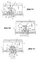
- FIGS. 2 and 3 each show a first embodiment of the invention Fastening system.
- the fastening system 11 comprises a screw means 12, which as Rotation transmission means 13 has a hex screw head, on which, as Actuating means for the screw 12 serving wrench attacking is.
- a collar 14 is formed at the screw head.
- the screw 12 with provided as a first threaded portion 15 formed external thread.
- the fastening system 11 comprises a contact element 18, which has a passage opening 19 for performing the screw means 12, which in a plate-shaped Section 20 of the contact element 18 is formed.
- a contact element 18 which has a passage opening 19 for performing the screw means 12, which in a plate-shaped Section 20 of the contact element 18 is formed.
- two webs 22 are arranged, which each having a projection 23.
- the webs 22 form with the plate-shaped portion 20 a bridge-like configuration of the contact element 18.
- the fastening system 11 comprises aellesschraubstoff 27 with one, the second Threaded section 28 forming internal thread which defines a mounting axis 29 and engageable with the first threaded portion 15 of the screw means 12.
- the Jacobschraubstoff 27 includes a rear engagement portion 31 and a contact portion 30, wherein the rear engagement portion 31 in the direction of the attachment axis 29 to the ganabterrorism 30 is spaced and connected thereto via the connecting portion 32 is.
- the surface 33 of the rear grip portion 31 of the Gegenschraubstoffs 27 extends substantially parallel to the surface 26 of the abutment portion 30 of the counter-screw means 27th
- Figs. 4a to 4c is an example of a mounting operation, the attachment of the C-shaped Mounting rail 3 shown as a first component on the carrier 1 as a second component.
- the fastening system 11 is factory made of the screw 12, the contact element 18 and the Gegenschraubstoff 27 to one, the user as a whole available Asked device composed.
- the C-shaped mounting rail 3 has her bottom portion 37 a plurality of slots 36.
- the C-shaped mounting rail 3 is in the recess 4 on the outside of the carrier arranged such that one of the slots 36 in the bottom portion 37 of the C-shaped mounting rail 3 via one of the openings 2 comes to rest on the outside of the carrier 1.
- the fastening system 11 as a whole in the direction of arrow 35 in the to be connected Components introduced so that the rear engagement portion 31 of the Gegenschraubstoffs 27th is passed through the slot 36 and the opening 2 and in the interior of the carrier 1 to lie comes.
- the distance B1 between the rear engagement part 31 and the abutment portion 30th the Jacobschraubstoffs 27 is at least the amount of the sum of the wall thickness the outer wall 38 of the carrier 1 and the wall thickness of the bottom portion 37 of the C-shaped Mounting rail 3.
- the width C of the rear grip part 31 is slightly smaller than the corresponding one clear width of the opening 2 in the outer wall 38 of the carrier 1 is formed.
- the contact element 18 is located with the webs 22 at the bottom portion 37 of the C-shaped Mounting rail 3, wherein, formed on the webs 22 projections 23 in the, from the slot 36 formed opening in the bottom portion 37 of the C-shaped mounting rail. 3 penetrate and serve as a guide and as a rotation for the contact element 18.
- the width D of the projections 23 is slightly smaller than the clear width of the slot 36 in Bottom portion 37 of the C-shaped mounting rail 3 is formed.
- the fastening system 11 as shown in Fig. 4b, in the direction of Arrow 39 is moved until the connecting portion 32 of the Jacobschraubstoffs 27 at the Wall 34 of the opening 2 in the outer wall 38 of the carrier 1 is present. It engages behind the rear engagement portion 31 a portion of the outer wall 38 of the carrier 1. means the projections 23 on the webs 22 of the contact element 18 is the fastening system 11 when moving in the slot 36 in the bottom portion 37 of the C-shaped Mounting rail 3 out.
- the distance A1 between the connecting portion 32 of the Schmidtraubstoffs 27 and the attachment axis 29 is selected such that the sum of the amount of the outer diameter E of the first threaded portion 15 on the screw 12 and the material thickness d of the connecting portion 32 about the clear width F of the opening 2 in the carrier first equivalent.
- the screw means 12 is at the, of the torque transmission means thirteenth opposite end provided with a stepped collar 16, the insertion of the Screwing facilitated in the opening 2 on the carrier 1. Is the amount of the clear width F the opening 2 is slightly smaller than the sum of the amount of the outer diameter of the E first threaded portion 15 on the screw means 12 and the material thickness d of the connecting portion 32, the fastening system 11 with the carrier 1 during insertion tighten the screw 12.
- Fig. 5 is a second embodiment of the invention with the fastening system 41 shown.
- the fastening system 41 has a screw 42 designed as a screw Screw with a designed as a torque transmitting means 43 screw head and an outer thread serving as the first threaded portion 45.
- the fastening system 41 further comprises a plate-shaped, rectangular abutment element 48, which on the open side 44 of the C-shaped mounting rail 5 is applied, and a Gegenschraubstoff 57.
- Gegenschraubstoff 57 points like the Gegenschraubstoff 27 a contact portion 61, a rear gripping portion 60 and a connecting portion connecting the rear grip portion 60 and the abutting portion 61 62 on.
- a guide sleeve 63 with the height H arranged for the screw 42, which is designed as a second threaded portion 58 Internal thread has.
- the second threaded portion 58 defines a mounting axis 59th
- the Schmidtschraubstoff 27 and Martinezschraubstoff 57 can both be independent Serve elements for a conventional fastening device.
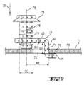
- Another embodiment of a Martinezschraubstoffs invention is shown in FIG. 7.
- the counter-screw 77 has a, the second threaded portion 78 forming internal thread on, which defines a mounting axis 79.
- the counter screw 77 also includes a rear engagement portion 81 and an abutment portion 80, wherein the rear engagement portion 81 spaced in the direction of the mounting axis 79 to the contact portion 80 is and is connected thereto via the connecting portion 82.
- the distance A2 between the connecting portion 82 and the fixing axis 79 corresponds about the amount of twice the diameter D2 of the second threaded portion 78.
- the surface 83 of the rear grip portion 81 of the Gegenschraubstoffs 77 runs in Substantially parallel to the surface 84 of the abutment portion 80 of Schmidtraubstoffs 27th
- the Gegenschraubstoff 77 is in the direction of arrow 70 in the opening 72 of the carrier 71st introduced, so that the rear engagement portion 81 of the Gegenschraubstoffs 77 inside the Carrier 71 comes to rest.
- the distance B2 between the rear grip part 81 and the abutment portion 80 of Gegenschraubstoffs 77 is at least the amount of wall thickness the outer wall 73 of the carrier 71.
- the Jacobschraubstoff 77 shifted until the connecting portion 82 of the Gegenschraubstoffs 77 on the wall 74 of the opening 72 in the outer wall 73 of the carrier 71 is present. It engages behind the Rear engaging portion 81 a portion of the outer wall 73.
- a screw 75 with a first threaded portion 76 is connected to the second threaded portion 78 of the Schmidtraubffens 77 engaged. For further operation of the screw 75 this is on the outer wall 73 of the carrier 71 and the contact portion 80 of Counter screw 77 is pulled against the direction of the arrow 70. It is the Rear engaging portion 81 with the outer wall 73 firmly brought into abutment and the Schwarzschraubstoff 77 clamped to the carrier 71.
Abstract
Description
Die Erfindung betrifft ein Befestigungssystem zum Befestigen eines ersten Bauteils an einem zweiten Bauteil, insbesondere zum Befestigen eines ersten Bauteils an einem Träger eines Montagesystems. Das Befestigungssystem umfasst ein, ein Drehmomentübertragungsmittel aufweisendes Schraubmittel, wobei das Schraubmittel zumindest bereichsweise einen ersten Gewindeabschnitt aufweist, ein Anlageelement zur Anlage an einem der Bauteile, wobei das Anlageelement eine Durchführöffnung zum Durchführen des Schraubmittels aufweist, und ein Gegenschraubmittel mit einem zweiten Gewindeabschnitt, der eine Befestigungsachse definiert und der mit dem ersten Gewindeabschnitt des Schraubmittels in Eingriff bringbar ist. Weiter betrifft die Erfindung ein Gegenschraubmittel, insbesondere für ein solches Befestigungssystem.The invention relates to a fastening system for fastening a first component to a second component, in particular for fastening a first component to a carrier of a Mounting system. The fastening system includes a torque transmitting means having screwing means, wherein the screw means at least partially a first Has threaded portion, a contact element for engagement with one of the components, wherein the Plant element has a passage opening for performing the screw means, and a Gegenschraubmittel with a second threaded portion having a mounting axis defined and which is engageable with the first threaded portion of the screw means. Furthermore, the invention relates to a Gegenschraubmittel, in particular for such a fastening system.
Im industriellen Leitungsbau und insbesondere im industriellen Rohrleitungsbau werden Stahlkonstruktionen aus Stahlbauelementen erstellt, welche skelettartig ein Traggerüst für die Leitungen bilden. Üblicherweise kommen Träger eines Montagesystems, welche beispielsweise einen geschlossenen Querschnitt aufweisen, oder Standardträger zur Anwendung, die mittels Verbindungsteilen oder Anschlusselementen miteinander zum gewünschten Traggerüst verbunden werden.In industrial line construction and in particular in industrial piping construction Steel structures created from steel components, which skeleton a support framework for form the lines. Usually come wearer of a mounting system, which, for example have a closed cross-section, or standard carrier for use, the by means of connecting parts or connecting elements with each other to the desired Shoring be connected.
An den Trägern müssen neben Anschlusselemente für andere Träger auch Anschlusselemente für die Leitungen oder Befestigungen angeordnet werden. Für die Verlegung von Leitungen im Allgemeinen und besonders von Rohrleitungen kommen oftmals C-förmige Montageschienen zum Einsatz, an denen mittels so genannter Schienenmuttern Rohrschellen und andere Befestigungselemente für die Leitungen schnell und kostengünstig fixiert werden können. On the carriers, in addition to connection elements for other carriers and connecting elements be arranged for the lines or fasteners. For the laying of cables in general and especially of pipelines often come C-shaped mounting rails used in which by means of so-called rail nuts pipe clamps and other fasteners for the lines are fixed quickly and inexpensively can.
Die Träger, insbesondere die Träger eines Montagesystems, sind oftmals mit Öffnungen in einem vordefinierten Abstand versehen, in denen weitere Bauteile mittels einer Schraubverbindung befestigt werden. Die Schraubverbindungen umfassen üblicherweise eine als Schraubmittel dienende Schraube, Unterlagsscheiben und eine als Gegenschraubmittel dienende Mutter. Die Unterlagsscheibe wird über den, den ersten Gewindeabschnitt aufweisenden Schraubenschaft der Schraube geschoben und anschliessend der Schraubenschaft durch das zu befestigende Bauteil und durch die Öffnung am Träger hindurchgeführt. Dann wird eine zweite Unterlagsscheibe sowie die, den zweiten Gewindeabschnitt aufweisende Mutter an dem freien Ende des Schraubenschafts angeordnet. Mittels Betätigung der Schraube bei gleichzeitigem Gegenhalten der Mutter wird die Schraubverbindung verspannt.The carriers, in particular the carriers of a mounting system, are often provided with openings in provided a predefined distance, in which further components by means of a screw connection be attached. The screw connections usually include one Screw-type screw, washers and one serving as Gegenschraubmittel Mother. The washer is over, the first threaded portion having Screw shaft of the screw pushed and then the screw shaft passed through the component to be fastened and through the opening on the carrier. Then is a second washer and the, the second threaded portion having Nut arranged at the free end of the screw shaft. By pressing the Screw while holding the nut, the screw is clamped.
Nachteilig an dieser bekannten Lösung ist, dass bei einem geschlossenen Hohlprofil oder bei einem nur einseitig zugänglichen Träger die herkömmlichen Schraubverbindungen nicht erstellt werden können, da ein Gegenhalten der Mutter zumeist nicht möglich ist.A disadvantage of this known solution is that in a closed hollow profile or at a one-sided accessible carrier does not create the conventional screw can be, because a holding the mother is usually not possible.
Um eine Befestigung von Bauteilen auch bei geschlossenen Hohlprofilen oder bei nur einseitig zugänglichen Trägern zu ermöglichen sind so genannte Einpressmuttern bekannt, welche in die Öffnungen am Träger gesteckt und mit einem Spezialwerkzeug verpresst werden. Diese Einpressmuttern weisen ein Innengewinde auf, in das ein Schraubmittel zur Befestigung eines Bauteils am Träger eingreifen kann.To attach components even with closed hollow sections or only on one side accessible supports are known so-called press-in nuts known which put into the openings on the carrier and be pressed with a special tool. These Press-in nuts have an internal thread into which a screw means for attachment a component can engage the carrier.
Nachteilig an dieser bekannten Lösung ist, dass die Öffnungen im Träger auf die Aussenabmessungen der Einpressmutter abgestimmt sein müssen, damit eine Verdrehsicherung der Einpressmutter am Träger gegeben ist. Das Setzen und Verpressen der Einpressmuttern am Träger stellt einen zusätzlichen Montageaufwand dar, welcher unter bestimmten Randbedingungen, wie z. B. in grosser Höhe und unter widrigen Umständen am Montageort, einen nicht zu unterschätzenden Aufwand darstellt. Bei einer Demontage oder Änderung der Leitungsführung oder der Tragkonstruktion verbleiben die Einpressmuttern am Träger, was beispielsweise aus konstruktiven und/oder ästhetischen Gründen oftmals nicht erwünscht ist.A disadvantage of this known solution is that the openings in the carrier to the outer dimensions the Einpressmutter must be tuned so that a rotation of the Pressing nut is given to the carrier. The setting and pressing of the press nuts on Carrier represents an additional installation effort, which under certain conditions, such as B. at high altitude and under adverse circumstances at the installation, a not to be underestimated. When disassembling or changing the cable routing or the support structure remain the Einpressmuttern on the carrier, which for example For structural and / or aesthetic reasons is often not desirable.
Aufgabe der Erfindung ist es, ein einfaches Befestigungssystem zur Befestigung eines ersten Bauteils an einem zweiten Bauteil zu schaffen, das einfach zu montieren, flexibel in der Anwendung und kostengünstig herstellbar ist. Eine weitere Aufgabe der Erfindung ist es, ein einfaches, flexibles und kostengünstig herstellbares Gegenschraubmittel zu schaffen.The object of the invention is to provide a simple fastening system for fastening a first To create a component on a second component that is easy to assemble, flexible in the Application and inexpensive to produce. Another object of the invention is to to provide simple, flexible and inexpensive to produce Gegenschraubmittel.
Die Aufgaben sind durch die Merkmale der unabhängigen Ansprüche gelöst. Vorteilhafte Weiterbildungen sind in den Unteransprüchen dargelegt. The objects are achieved by the features of the independent claims. advantageous Further developments are set forth in the subclaims.
Gemäss der Erfindung weist das Gegenschraubmittel einen Hintergreifabschnitt und einen Anlageabschnitt auf, wobei der Hintergreifabschnitt in Richtung der Befestigungsachse zu dem Anlageabschnitt beabstandet und mit dem Anlageabschnitt über einen Verbindungsabschnitt verbunden ist.According to the invention, the Gegenschraubmittel a Hintergreifabschnitt and a Anlageabschnitt, wherein the rear engagement portion in the direction of the mounting axis to the contact portion spaced and with the contact portion via a connecting portion connected is.
Der Hintergreifabschnitt des Gegenschraubmittels ist in die Öffnung des ersten Bauteils und in die Öffnung des zweiten Bauteils, z. B. in die Öffnungen eines Trägers eines Montagesystems, der einen geschlossenen Hohlquerschnitt aufweist, einführbar. Der Anlageabschnitt ist in seinen Abmessungen derart ausgestaltet, dass dieser beispielsweise an dem zu befestigenden ersten Bauteil anliegt und das Gegenschraubmittel nicht durch die Öffnungen in das zweite Bauteil fallen kann. Das erfindungsgemässe Befestigungssystem ist neben nur einseitig zugänglichen, mit Öffnungen versehenen Trägern auch bei jeder anderen Art und Ausgestaltung eines Trägers anwendbar, sofern dieser mit Öffnungen versehen ist, in die der Hintergreifabschnitt des Gegenschraubmittels einführbar ist. Der Abstand des Hintergreifabschnitts zu dem Anlageabschnitt entspricht zur Befestigung eines ersten Bauteils an einem zweiten Bauteil vorzugsweise zumindest der Summe aus der Wandungsstärke des ersten Bauteils und der der Wandungsstärke des zweiten Bauteils.The rear engagement portion of the Gegenschraubmittels is in the opening of the first component and in the opening of the second component, for. B. in the openings of a carrier of a mounting system, which has a closed hollow cross section, insertable. The investment section is in its dimensions designed such that this example, to be attached to the first component is applied and the Gegenschraubmittel not through the openings in the second component can fall. The inventive fastening system is next to only one side accessible, apertured straps in any other type and design a beam, provided that it has openings in which the Hintergreifabschnitt of Gegenschraubmittels is inserted. The distance of the rear grip section to the abutment portion corresponds to the attachment of a first component to a second component preferably at least the sum of the wall thickness of the first Component and the wall thickness of the second component.
Das erste Bauteil weist zumindest an dem Elementabschnitt, welcher an dem zweiten Bauteil zu liegen kommt, eine Durchführöffnung auf, die vorteilhafterweise als Langloch ausgebildet ist. Bei ersten Bauteilen, die mehrere Elementabschnitte aufweisen, sind zu deren flexiblen Verwendung vorzugsweise an jedem der Elementabschnitte Durchführöffnungen ausgebildet. Zur Montage des erfindungsgemässen Befestigungssytems wird das erste Bauteil ausgerichtet mit seiner Öffnung über eine der Öffnungen am zweiten Bauteil angeordnet. Das Hintergreifteil des Gegenschraubmittels wird durch die beiden Öffnungen eingeführt. Anschliessend wird das Anlageelement des Befestigungssystems angeordnet und durch dessen Durchführöffnung wird das Schraubmittel hindurchgeführt, wobei der erste Gewindeabschnitt an dem Schraubmittel mit dem zweiten Gewindeabschnitt des Gegenschraubmittels in Eingriff gebracht wird. Das zusammengesetzte Befestigungssystem wird seitlich verschoben, bis der Verbindungsabschnitt des Gegenschraubmittels an einen Rand der Öffnung im zweiten Bauteil zu liegen kommt. Mittels eines geeigneten Mittels, z. B. mittels eines Schraubenschlüssels der beispielsweise an einem als Drehübertragungsmittel dienenden Sechskant-Schraubenkopf des Schraubmittels angreift, wird das Schraubmittel betätigt und das erfindungsgemässe Befestigungssystem verspannt. Dabei wird das Gegenschraubmittel in Richtung des, sich am ersten oder zweiten Bauteil abstützenden Anlageelement gezogen, wobei das erste Bauteil an dem zweiten Bauteil befestigt, beziehungsweise fixiert wird. The first component has at least on the element portion, which on the second component comes to rest, a passage opening, which advantageously formed as a slot is. In the case of first components which have a plurality of element sections, the latter are flexible Use preferably formed on each of the element sections through openings. For mounting the attachment system according to the invention, the first component is aligned arranged with its opening over one of the openings on the second component. The Hintergreifteil the Gegenschraubmittels is introduced through the two openings. Subsequently is arranged the contact element of the fastening system and by the Through opening the screw is passed, wherein the first threaded portion on the screw means with the second threaded portion of the counter screw means is engaged. The assembled fastening system is shifted laterally, until the connecting portion of the Gegenschraubmittels to an edge of the opening in second component comes to rest. By means of a suitable agent, for. B. by means of a wrench for example, on a hexagonal screw head serving as a rotation transmitting means engages the screw means, the screw means is actuated and the clamped fastening system according to the invention. In this case, the Gegenschraubmittel in Direction of the, supported on the first or second component supporting element, wherein the first component is fastened or fixed to the second component.
Das Schraubmittel ist vorzugsweise eine Schraube mit einem, als erster Gewindeabschnitt dienendem Aussengewinde und mit einem Schraubenkopf, dessen Aussendurchmesser grösser als der Innendurchmesser der Durchführöffnung im Anlageelement ist. An dem Schraubenkopf kann ein, den Aussendurchmesser des Schraubenkopfs vergrössernder Bund oder eine entsprechende Unterlagsscheibe angeordnet sein, beziehungsweise werden.The screw means is preferably a screw with a, as the first threaded portion serving external thread and with a screw head whose outside diameter greater than the inner diameter of the passage opening in the contact element. To the Screw head can be one, the outer diameter of the screw head enlarging Bund or a corresponding washer can be arranged, or be.
Der Anlageabschnitt des Gegenschraubmittels ist vorzugsweise im Wesentlichen als Mutter ausgebildet, wobei der zweite Gewindeabschnitt ein, in einer Öffnung angeordnetes Innengewinde ist. In einer Variante dazu, ist an dem Anlageabschnitt des Gegenschraubmittels ein Abschnitt mit einem, als zweiter Gewindeabschnitt dienendem Aussengewinde vorgesehen, an welchem ein zumindest bereichsweise hülsenartig ausgebildetes Schraubmittel, mit einem als erster Gewindeabschnitt ausgebildetem Innengewinde ausgeformt ist, welches mit dem Aussengewinde des Gegenschraubmittels in Eingriff bringbar ist.The abutment portion of the Gegenschraubmittels is preferably substantially as a mother formed, wherein the second threaded portion a, arranged in an opening internal thread is. In a variant of this, is at the contact portion of the Gegenschraubmittels a Section provided with, serving as a second threaded portion male thread, at which an at least partially sleeve-like trained screw, with a formed as a first threaded portion formed internal thread, which with the external thread of Gegenschraubmittels can be brought into engagement.
Das erfindungsgemässe Befestigungssystem wird entweder in Einzelteilen oder bereits werkseitig zusammengeführt dem Anwender zur Verwendung zur Verfügung gestellt. Das Schraubmittel, das Anlageelement und/oder das Gegenschraubmittel sind bevorzugt aus Metall, vorteilhafterweise aus einem rostfreien Stahl gefertigt. Je nach den Belastungen und äusseren Bedingungen können das Schraubmittel, das Anlageelement und/oder das Gegenschraubmittel aus einem Kunststoff hergestellt sein.The inventive fastening system is either in individual parts or already factory-assembled, provided to the user for use. The Screw means, the contact element and / or Gegenschraubmittel are preferably made Metal, advantageously made of stainless steel. Depending on the loads and external conditions may be the screw, the contact element and / or Gegenschraubmittel be made of a plastic.
Vorzugsweise entspricht der Abstand zwischen dem Verbindungsabschnitt und der Befestigungsachse maximal dem Betrag des dreifachen Durchmessers des zweiten Gewindeabschnittes. Durch diese Ausgestaltung können die auftretenden Biegespannungen im Gegenschraubmittel beim Verspannen des Befestigungssystems mit weitgehend geringen Materialstärken des verwendeten Materials zur Fertigung des Gegenschraubmittels übernommen und das Gegenschraubmittel wirtschaftlich hergestellt werden. Vorteilhafterweise entspricht der Abstand zwischen dem Verbindungsabschnitt und der Befestigungsachse weniger als dem Betrag des einfachen Durchmessers des zweiten Gewindeabschnittes, womit das Gegenschraubmittel in der Materialstärke optimiert und somit kostengünstig herstellbar ist. Die gesamten Aussenabmessungen des Gegenschraubmittels können klein gehalten werden, womit das gesamte Befestigungssystem auch bei engen Platzverhältnissen einfach händelbar ist. Vorteilhafterweise ist der Abstand zwischen dem Verbindungsabschnitt und der Befestigungsachse derart gewählt, dass der Betrag der Summe aus dem Aussendurchmesser des Schraubmittels und der Materialstärke des Verbindungsabschnittes des Gegenschraubmittels der Grösse der Öffnung im zweiten Bauteil entspricht. Bei dieser Ausführungsform liegt der Verbindungsabschnitt des Gegenschraubmittels an der Öffnungsbegrenzung im zweiten Bauteil an und die Biegebelastung zwischen dem Hintergreifabschnitt und dem Verbindungsabschnitt des Gegenschraubmittels ist marginal, womit das Gegenschraubmittel bezüglich der Materialstärke optimiert und kostengünstig gefertigt werden kann.Preferably, the distance between the connecting portion and the attachment axis corresponds at most the amount of three times the diameter of the second threaded portion. By this configuration, the bending stresses occurring in Gegenschraubmittel when bracing the fastening system with largely low material thicknesses taken over of the material used for the production of Gegenschraubmittels and the Gegenschraubmittel be produced economically. Advantageously corresponds the distance between the connecting portion and the mounting axis less than the amount of the simple diameter of the second threaded portion, whereby the Gegenschraubmittel optimized in material thickness and thus is inexpensive to produce. The total external dimensions of the counter screw means can be kept small, which makes the entire fastening system easy to handle, even in confined spaces is. Advantageously, the distance between the connecting portion and the mounting axis chosen such that the amount of the sum of the outer diameter the screw means and the material thickness of the connecting portion of the Gegenschraubmittels the size of the opening in the second component corresponds. In this embodiment is the connecting portion of the Gegenschraubmittels at the opening limit in second component and the bending load between the rear engagement portion and the connecting portion the Gegenschraubmittels is marginal, bringing the Gegenschraubmittel optimized in terms of material thickness and can be manufactured inexpensively.
Bevorzugt ist zumindest eine der Oberflächen des Hintergreifabschnitts im Wesentlichen parallel zu einer der Oberflächen des Anlageabschnitts ausgerichtet. Dieses Gegenschraubmittel kann einfach in den Öffnungen des ersten und zweiten Bauteils eingeführt und in diesen verschoben werden. In einer Variante dazu, schliesst eine in der, mit dem Träger in Anlage kommende Oberfläche des Hintergreifabschnitts verlaufende Ebene mit der, von der in Anlage kommende Ebene des Anlageabschnitts einen spitzen Winkel ein, so dass beim Verspannen des Befestigungssystems eine gewisse Federwirkung zwischen dem Gegenschraubmittel und dem zweiten Bauteil geschaffen wird. Diese Federwirkung ist besonders bei dynamischen Belastungen auf das Befestigungssystem vorteilhaft.Preferably, at least one of the surfaces of the rear grip portion is substantially aligned parallel to one of the surfaces of the abutment section. This counter screw can be easily inserted into the openings of the first and second component and to be moved into these. In a variant of this, one closes in, with the wearer in Appendix coming surface of the rear grip section extending plane with the, from the in abutting plane of the contact section an acute angle, so that when Bracing the fastening system a certain spring action between the Gegenschraubmittel and the second component is created. This spring effect is special advantageous for dynamic loads on the fastening system.
Vorteilhafterweise ist an dem Anlageabschnitt des Gegenschraubmittels eine Führungshülse für das Schraubmittel angeordnet. Diese Ausführung des Gegenschraubmittels ist besonders bei grossen Abständen zwischen dem Gegenschraubmittel und dem Anlageelement vorteilhaft, da das Schraubmittel in der Führungshülse insbesondere beim Einführen des Schraubmittels geführt wird und so die Montage des erfindungsgemässen Befestigungssystems erleichtert ist. Bevorzugt ist der zweite Gewindeabschnitt an, beziehungsweise in der Führungshülse ausgebildet. Durch die Verlängerung der Gewindegänge des zweiten Gewindeabschnittes können höhere Belastungen von dem erfindungsgemässen Befestigungssystem übernommen werden.Advantageously, at the contact portion of the Gegenschraubmittels a guide sleeve arranged for the screw. This version of Gegenschraubmittels is special advantageous at large distances between the Gegenschraubmittel and the contact element, because the screw in the guide sleeve in particular during insertion of the Screwing is performed and so the installation of the inventive fastening system is relieved. Preferably, the second threaded portion is on, or in the Guiding sleeve formed. By extending the threads of the second threaded section can higher loads on the inventive fastening system be taken over.
Vorzugsweise weist das Anlageelement eine im Wesentlichen plattenförmige, im Grundriss beispielsweise rechteckige Ausgestaltung auf, mit einer ersten und einer zweiten, einander gegenüberliegenden Flachseite. Die Aussenabmessungen des Anlageelementes werden derart gewählt, dass das Anlageelement zumindest teilweise, jedoch vorteilhaft an zwei gegenüberliegenden Seiten der Durchführöffnungen in dem ersten Bauteil, beziehungsweise an zumindest einem Elementabschnitt des ersten Bauteils anliegt.Preferably, the abutment element has a substantially plate-shaped, in plan view For example, rectangular configuration, with a first and a second, each other opposite flat side. The external dimensions of the contact element are chosen such that the contact element at least partially, but advantageously on two opposite Side of the passage openings in the first component, respectively abuts on at least one element portion of the first component.
Bevorzugt weist das Anlageelement an zwei seiner gegenüberliegenden Längsseiten Stege auf. Die beiden Stege sind an der gleichen Flachseite des Anlageelementes angeordnet, so dass dieses im Querschnitt durch die Stege eine brückenartige Ausgestaltung aufweist. Die Höhe der Stege wird vorzugsweise derart gewählt, dass der Freiraum zwischen der Oberkante des Anlageabschnittes des Gegenschraubmittels und der Unterkante des Anlageelementes grösser oder zumindest gleich dem Verspannweg ist, den das Gegenschraubmittel zur ausreichenden Befestigung, beziehungsweise Fixierung des ersten Bauteils an dem zweiten Bauteil beim Betätigen des Schraubmittels zurücklegen muss. Preferably, the contact element has webs on two of its opposite longitudinal sides on. The two webs are arranged on the same flat side of the contact element, so that this has a bridge-like configuration in cross-section through the webs. The Height of the webs is preferably selected such that the free space between the top edge of the abutment portion of the Gegenschraubmittels and the lower edge of the contact element greater or at least equal to the Verspannweg is the Gegenschraubmittel for sufficient attachment, or fixation of the first component to the second component when operating the screw must cover.
Vorteilhafterweise ist an den Stegen des Anlageelementes zumindest ein Vorsprung ausgebildet. Die Breite des zumindest einen Vorsprungs beträgt bevorzugt weniger als die Breite der Durchführöffnung im ersten Bauteil. Dadurch kann der zumindest eine Vorsprung an den Stegen des Anlageelementes in die Durchführöffnung eindringen und beim Betätigen des Schraubmittels als Verdrehsicherung für das Anlageelement dienen. Handelt es sich bei der Durchführöffnung im ersten Bauteil um ein Langloch, bildet der zumindest eine Vorsprung an den Stegen des Anlageelementes eine Führung beim Verschieben des Anlageelementes entlang der Längsachse des Langlochs.Advantageously, at least one projection is formed on the webs of the contact element. The width of the at least one projection is preferably less than the width the passage opening in the first component. As a result, the at least one projection on the Ridges of the contact element penetrate into the passage opening and when pressing the Screwing serve as rotation for the investment element. Is it the case of Through opening in the first component to a slot, which forms at least one projection the webs of the contact element a guide when moving the contact element along the longitudinal axis of the slot.
Vorzugsweise sind an den Stegen des Anlageelementes gegeneinander ausgerichtete Rastnasen zum bereichsweisen Halten des Gegenschraubmittels an dem Anlageelement im zusammengeführten Zustand des Anlageelementes und des Gegenschraubmittels ausgebildet. Die Rastnasen bilden eine Verliersicherung und zugleich eine Montagehilfe bei einem Befestigungssystem, bei dem zumindest das Anlageelement und das Gegenschraubmittel zusammengeführt sind.Preferably, mutually aligned locking lugs on the webs of the contact element for partially holding the Gegenschraubmittels on the contact element in the merged Condition of the contact element and the Gegenschraubmittels trained. The locking lugs form a captive and at the same time an assembly aid in a fastening system, in which at least the contact element and the Gegenschraubmittel combined are.
Ein erfindungsgemässes Gegenschraubmittel mit einem zweiten Gewindeabschnitt, der eine Befestigungsachse definiert, insbesondere für ein zuvor ausgeführtes Befestigungssystem, weist einen Hintergreifabschnitt und einen Anlageabschnitt auf, wobei der Hintergreifabschnitt in Richtung der Befestigungsachse zu dem Anlageabschnitt beabstandet und mit dem Anlageabschnitt über einen Verbindungsabschnitt verbunden ist. Das erfindungsgemässe Gegenschraubmittel schafft ein, von aussen zugänglichen zweiten Gewindeabschnitt, in den ein Schraubmittel zur Befestigung eines ersten Bauteils an einem zweiten Bauteil einführbar ist. Des Weiteren kann mit dem erfindungsgemässen Gegenschraubmittel an einem zweiten Bauteil ein Befestigungspunkt geschaffen werden.An inventive Gegenschraubmittel with a second threaded portion, the one Fixing axis defined, in particular for a previously executed fastening system, has a rear engagement portion and a contact portion, wherein the rear engagement portion spaced in the direction of the mounting axis to the contact portion and with the Anlageabschnitt is connected via a connecting portion. The inventive Gegenschraubmittel creates a, accessible from the outside second threaded portion in the a screw means for fixing a first component to a second component insertable is. Furthermore, with the inventive Gegenschraubmittel on a second Component to be created an attachment point.
Der Hintergreifabschnitt des Gegenschraubmittels ist in die Durchführöffnung des ersten Bauteils und/oder in die Öffnung des zweiten Bauteils, z. B. in die Öffnungen eines Trägers eines Montagesystems, der einen geschlossenen Hohlquerschnitt aufweist, einführbar. Der Anlageabschnitt ist in seinen Abmessungen derart ausgestaltet, dass dieser an dem ersten und/oder an dem zweiten Bauteil anliegt und das Gegenschraubmittel nicht durch die Öffnung am zweiten Bauteil in dieses hineinfallen kann. Das erfindungsgemässe Gegenschraubmittel ist neben nur einseitig zugänglichen, mit Öffnungen versehenen Trägern auch bei jeder Art von Träger anwendbar, sofern dieser mit Öffnungen versehen ist, in die der Hintergreifabschnitt des Gegenschraubmittels einführbar ist. Der Abstand des Hintergreifabschnitts zu dem Anlageabschnitt entspricht zur Befestigung eines ersten Bauteils an einem zweiten Bauteil zumindest der Summe aus der Wandungsstärke des ersten Bauteils und der der Wandungsstärke des zweiten Bauteils. The Hintergreifabschnitt of Gegenschraubmittels is in the passage opening of the first Component and / or in the opening of the second component, for. B. in the openings of a carrier a mounting system having a closed hollow section, insertable. Of the Anlageabschnitt is designed in its dimensions such that this at the first and / or rests against the second component and the Gegenschraubmittel not through the opening on the second component can fall into this. The Gegenschraubmittel invention is next to only unilaterally accessible, apertured straps too applicable to any type of carrier, provided that it is provided with openings into which the rear engagement section the Gegenschraubmittels is insertable. The distance of the rear grip section to the abutment portion corresponds to the attachment of a first component to a second component at least the sum of the wall thickness of the first component and the the wall thickness of the second component.
Mittels des erfindungsgemässen Gegenschraubmittel kann ein, von aussen zugänglicher Befestigungspunkt, beispielsweise für ein Schraubmittel, an einem zweiten Bauteil geschaffen werden. Der Abstand des Hintergreifabschnitts eines solchen Gegenschraubmittels zu dem Anlageabschnitt entspricht zumindest der Wandungsstärke des zweiten Bauteils. Das Hintergreifteil des Gegenschraubmittels wird durch die Öffnung an dem zweiten Bauteil eingeführt. Anschliessend wird ein Schraubmittel mit einem ersten Gewindeabschnitt mit dem zweiten Gewindeabschnitt des Gegenschraubmittels in Eingriff gebracht. Das Schraubmittel wird betätigt und die, das erfindungsgemässe Gegenschraubmittel umfassende Vorrichtung verspannt.By means of the counter-screw means according to the invention, an externally accessible one can be obtained Attachment point, for example, for a screw, created on a second component become. The distance of the Hintergreifabschnitts of such Gegenschraubmittels to the contact section corresponds at least to the wall thickness of the second component. The Rear engaging part of the Gegenschraubmittels is inserted through the opening on the second component. Subsequently, a screw means with a first threaded portion with the second threaded portion of the Gegenschraubmittels engaged. The screwdriver is operated and the, the inventive Gegenschraubmittel comprehensive device braced.
Das mit dem erfindungsgemässen Gegenschraubmittel zusammenwirkende Schraubmittel ist vorzugsweise eine Schraube mit einem, als erster Gewindeabschnitt dienendem Aussengewinde und mit einem Schraubenkopf. An dem Schraubenkopf kann ein, den Aussendurchmesser des Schraubenkopfs vergrössernder Bund oder eine entsprechende Unterlagsscheibe angeordnet sein, beziehungsweise werden.The cooperating with the inventive Gegenschraubmittel screw is preferably a screw with a, serving as a first threaded portion male thread and with a screw head. On the screw head can be one, the outside diameter screw head enlarging collar or a corresponding washer be arranged, or be.
Der Anlageabschnitt des erfindungsgemässen Gegenschraubmittels ist vorzugsweise im Wesentlichen als Mutter ausgebildet, wobei der zweite Gewindeabschnitt ein, in einer Öffnung angeordnetes Innengewinde ist. In einer Variante dazu, ist an dem Anlageabschnitt des Gegenschraubmittels ein Abschnitt mit einem, als zweiter Gewindeabschnitt dienendes Aussengewinde vorgesehen, an welchem ein zumindest bereichsweise hülsenartig ausgebildetes Schraubmittel, mit einem als erster Gewindeabschnitt ausgebildetes Innengewinde ausgeformt ist, welches mit dem Aussengewinde des Gegenschraubmittels in Eingriff bringbar ist.The abutment portion of the Gegenschraubmittels invention is preferably in Substantially formed as a nut, wherein the second threaded portion, in an opening arranged internal thread is. In a variant of this, is at the contact section of the Gegenschraubmittels a section with a, serving as a second threaded portion male thread provided on which an at least partially sleeve-like trained Screwing, formed with a trained as a first threaded portion internal thread is, which can be brought into engagement with the external thread of Gegenschraubmittels is.
Vorzugsweise entspricht der Abstand zwischen dem Verbindungsabschnitt und der Befestigungsachse maximal dem Betrag des dreifachen Durchmessers des zweiten Gewindeabschnittes. Durch diese Ausgestaltung können die auftretenden Biegespannungen im Gegenschraubmittel beim Verspannen mittels eines Schraubmittels mit weitgehend geringen Materialstärken des verwendeten Materials zur Fertigung des Gegenschraubmittels übernommen und das Gegenschraubmittel wirtschaftlich hergestellt werden. Vorteilhafterweise entspricht der Abstand zwischen dem Verbindungsabschnitt und der Befestigungsachse weniger als dem Betrag des einfachen Durchmessers des zweiten Gewindeabschnittes, womit das Gegenschraubmittel in der Materialstärke optimiert werden kann und somit kostengünstig herstellbar ist. Die gesamten Aussenabmessungen des Gegenschraubmittels können klein gehalten werden, womit dieses auch bei engen Platzverhältnissen einfach händelbar ist. Preferably, the distance between the connecting portion and the attachment axis corresponds at most the amount of three times the diameter of the second threaded portion. By this configuration, the bending stresses occurring in Gegenschraubmittel during clamping by means of a screw means with largely low material thicknesses taken over of the material used for the production of Gegenschraubmittels and the Gegenschraubmittel be produced economically. Advantageously corresponds the distance between the connecting portion and the mounting axis less than the amount of the simple diameter of the second threaded portion, whereby the Gegenschraubmittel can be optimized in material thickness and thus inexpensive to produce is. The entire outer dimensions of the Gegenschraubmittels can be small be held, which is easy to handle even in tight spaces.
Bevorzugt ist zumindest eine der Oberflächen des Hintergreifabschnitts im Wesentlichen parallel zu einer der Oberflächen des Anlageabschnitts ausgerichtet. Diese Ausführungsform des erfindungsgemässen Gegenschraubmittels kann einfach in den Öffnungen des ersten und/oder zweiten Bauteils eingeführt und in diesen verschoben werden. In einer Variante dazu, schliesst eine in der, mit dem Träger in Anlage kommende Oberfläche des Hintergreifabschnitts verlaufende Ebene mit der, von der in Anlage kommende Ebene des Anlageabschnitts einen spitzen Winkel ein, so dass beim Verspannen des Befestigungssystems eine gewisse Federwirkung zwischen dem Gegenschraubmittel und dem zweiten Bauteil geschaffen wird. Diese Federwirkung ist besonders bei dynamischen Belastungen auf das Befestigungssystem vorteilhaft.Preferably, at least one of the surfaces of the rear grip portion is substantially aligned parallel to one of the surfaces of the abutment section. This embodiment The Gegenschraubmittels invention can easily in the openings of the first and / or second component introduced and moved into this. In a variant for this purpose, a closes in the, with the carrier abutting surface of the Hintergreifabschnitts extending plane with, coming from the plant in the plant section an acute angle, so that when tightening the fastening system a created certain spring action between the Gegenschraubmittel and the second component becomes. This spring effect is particularly with dynamic loads on the fastening system advantageous.
Vorteilhafterweise ist an dem Anlageabschnitt des Gegenschraubmittels eine Führungshülse für ein Schraubmittel angeordnet. Die Führungshülse des erfindungsgemässen Gegenschraubmittels ermöglicht die Führung eines Schraubmittels, wie eine Schraube mit einem Aussengewinde und Schraubenkopf, beim Einführen desselben, so dass die Montage der Schraubverbindung erleichtert wird. Bevorzugt ist der zweite Gewindeabschnitt an, beziehungsweise in der Führungshülse ausgebildet. Durch die Verlängerung der Gewindegänge des zweiten Gewindeabschnittes gegenüber den zuvor beschriebenen Ausführungen des erfindungsgemässen Gegenschraubmittels können höhere Belastungen von diesem übernommen werden.Advantageously, at the contact portion of the Gegenschraubmittels a guide sleeve arranged for a screwdriver. The guide sleeve of the inventive Gegenschraubmittels allows the guidance of a screw, like a screw with a External thread and screw head, during insertion of the same, so that the assembly of Screw connection is facilitated. Preferably, the second threaded portion is on, or formed in the guide sleeve. By extending the threads the second threaded portion with respect to the previously described embodiments of according to the invention Gegenschraubmittels higher loads can be taken from this become.
Aus der nachfolgenden Detailbeschreibung und der Gesamtheit der Patentansprüche ergeben sich weitere vorteilhafte Ausführungsformen und Merkmalskombinationen der Erfindung.From the following detailed description and the totality of the claims result further advantageous embodiments and feature combinations of the invention.
Die Erfindung wird nachstehend anhand mehrerer Ausführungsbeispiele näher erläutert. Es zeigen:
- Fig. 1
- Eine perspektivische Ansicht eines Trägers eines Montagesystems mit mehreren an diesem, mittels des erfindungsgemässen Befestigungssystem befestigten Bauteilen;
- Fig. 2
- eine perspektivische Ansicht eines ersten Ausführungsbeispiel des erfindungsgemässen Befestigungssystem;
- Fig. 3
- eine Seitenansicht des in Fig. 2 dargestellten Befestigungssystems in Explosionsdarstellung;
- Fig. 4a-c
- einen Längsschnitt entlang der Linie IV-IV in Fig. 1 durch das in der Fig. 2 dargestellten Befestigungssystems in drei Montageschritten;
- Fig. 5
- einen Querschnitt entlang der Linie V-V in Fig. 1;
- Fig. 6
- eine Ansicht eines zweiten Ausführungsbeispiels des Hintergreifteils des erfindungsgemässen Befestigungssystems; und
- Fig. 7
- eine Teilansicht eines erfindungsgemässen Gegenschraubmittels.
- Fig. 1
- A perspective view of a support of a mounting system with a plurality of this, fastened by means of the inventive fastening system components;
- Fig. 2
- a perspective view of a first embodiment of the inventive fastening system;
- Fig. 3
- a side view of the fastening system shown in Figure 2 in an exploded view.
- Fig. 4a-c
- a longitudinal section along the line IV-IV in Figure 1 by the fastening system shown in Figure 2 in three assembly steps.
- Fig. 5
- a cross section along the line VV in Fig. 1;
- Fig. 6
- a view of a second embodiment of the rear engagement part of the inventive fastening system; and
- Fig. 7
- a partial view of an inventive Gegenschraubmittels.
Grundsätzlich sind in den Figuren gleiche Teile mit den gleichen Bezugszeichen versehen.Basically, the same parts are provided with the same reference numerals in the figures.
In der Fig. 1 ist ein Träger 1 eines Montagesystems gezeigt, der einen im Querschnitt geschlossenen
Hohlquerschnitt und an seinen Aussenwandungen mehrere, in einem definierten
Abstand angeordnete Öffnungen 2 aufweist. An dem, das zweite Bauteil bildenden Träger
1 sind verschiedene Beispiele von ersten Bauteilen mittels erfindungsgemässen Befestigungssystemen
11, bzw. 41 befestigt.In Fig. 1, a
Beispielsweise ist ein Abschnitt 3 einer C-förmigen Montageschiene in einer Vertiefung 4 an
der Aussenseite des Trägers 1 mit dem erfindungsgemässen Befestigungssystem 11 befestigt.
Eine nur abschnittsweise dargestellte C-förmige Montageschiene 5 ist im Wesentlichen
rechtwinklig zu der Längsachse der Vertiefung 4 an der Aussenseite des Trägers 1 mit dem
erfindungsgemässen Befestigungssystem 41 befestigt. Eine, in einem Winkel zu der Längsachse
der Vertiefung 4 an der Aussenseite des Trägers 1 verlaufende C-förmige Montageschiene
6 ist an einem Montageteil 7 fixiert, welches in der Vertiefung 4 an der Aussenseite
des Trägers 1 angeordnet und mittels zwei erfindungsgemässen Befestigungssystemen 11
an dem Träger 1 befestigt ist. Ein Winkelelement 8 beispielsweise zur Befestigung eines
Rohrbogens ist in der Vertiefung 9 an einer anderen Aussenseite des Trägers 1 mittels eines
erfindungsgemässen Befestigungssystems 11 befestigt. Als letztes, jedoch nicht abschliessendes
Beispiel eines ersten Bauteils ist in der Vertiefung 9 an einer anderen Aussenseite
des Trägers 1 ein Anschlusselement 10 für den Anschluss eines weiteren Trägers oder einer
Montageschiene mittels zumindest eines erfindungsgemässen Befestigungssystems 11 an
dem Träger 1 befestigt.For example, a
Die Fig. 2 und Fig. 3 zeigen jeweils ein erstes Ausführungsbeispiel des erfindungsgemässen
Befestigungssystems. Das Befestigungssystem 11 umfasst ein Schraubmittel 12, das als
Drehübertragungsmittel 13 einen Sechskant-Schraubenkopf aufweist, an welchem ein, als
Betätigungsmittel für das Schraubmittel 12 dienender Schraubenschlüssel in Angriff bringbar
ist. An dem Schraubenkopf ist ein Bund 14 ausgeformt. Weiter ist das Schraubmittel 12 mit
einem als erster Gewindeabschnitt 15 ausgebildetem Aussengewinde versehen.FIGS. 2 and 3 each show a first embodiment of the invention
Fastening system. The
Weiter umfasst das Befestigungssystem 11 ein Anlageelement 18, welches eine Durchführöffnung
19 zum Durchführen des Schraubmittels 12 aufweist, die in einem plattenförmigen
Abschnitt 20 des Anlageelementes 18 ausgebildet ist. An zwei sich gegenüberliegenden
Längsseiten 21 des plattenförmigen Abschnitts 20 sind zwei Stege 22 angeordnet, welche
jeweils einen Vorsprung 23 aufweisen. Die Stege 22 bilden mit dem plattenförmigen Abschnitt
20 eine brückenartige Ausgestaltung des Anlageelementes 18. An den Stegen 22
sind jeweils zwei, gegeneinander ausgerichtete Rastnasen 24 ausgebildet.Furthermore, the
Weiter umfasst das Befestigungssystem 11 ein Gegenschraubmittel 27 mit einem, den zweiten
Gewindeabschnitt 28 bildenden Innengewinde, welches eine Befestigungsachse 29 definiert
und mit dem ersten Gewindeabschnitt 15 des Schraubmittels 12 in Eingriff bringbar ist.
Das Gegenschraubmittel 27 umfasst einen Hintergreifabschnitt 31 und einen Anlageabschnitt
30, wobei der Hintergreifabschnitt 31 in Richtung der Befestigungsachse 29 zu dem
Anlageabschnitt 30 beabstandet ist und mit diesem über den Verbindungsabschnitt 32 verbunden
ist. Die Oberfläche 33 des Hintergreifabschnitts 31 des Gegenschraubmittels 27 verläuft
im Wesentlichen parallel zu der Oberfläche 26 des Anlageabschnitts 30 des Gegenschraubmittels
27.Furthermore, the
In den Fig. 4a bis 4c ist als Beispiel für einen Montagevorgang die Befestigung der C-förmigen
Montageschiene 3 als erstes Bauteil an dem Träger 1 als zweites Bauteil dargestellt.
Das Befestigungssystem 11 ist werkseitig aus dem Schraubmittel 12, dem Anlageelement
18 und dem Gegenschraubmittel 27 zu einer, dem Anwender als Ganzes zur Verfügung
gestellte Vorrichtung zusammengesetzt. Die C-förmige Montageschiene 3 weist an
ihrem Bodenabschnitt 37 mehrere Langlöcher 36 auf. Die C-förmige Montageschiene 3 wird
in der Vertiefung 4 an der Aussenseite des Trägers derart angeordnet, dass eines der Langlöcher
36 im Bodenabschnitt 37 der C-förmigen Montageschiene 3 über einer der Öffnungen
2 an der Aussenseite des Trägers 1 zu liegen kommt.In Figs. 4a to 4c is an example of a mounting operation, the attachment of the C-shaped
Das Befestigungssystem 11 wird als Ganzes in Richtung des Pfeils 35 in die zu verbindenden
Bauteile eingeführt, so dass der Hintergreifabschnitt 31 des Gegenschraubmittels 27
durch das Langloch 36 und die Öffnung 2 hindurchgeführt ist und im Innern des Trägers 1 zu
liegen kommt. Der Abstand B1 zwischen dem Hintergreifteil 31 und dem Anlageabschnitt 30
des Gegenschraubmittels 27 beträgt zumindest dem Betrag der Summe aus der Wandstärke
der Aussenwandung 38 des Trägers 1 und der Wandstärke des Bodenabschnittes 37 der C-förmigen
Montageschiene 3. Die Breite C des Hintergreifteils 31 ist etwas kleiner als die entsprechende
lichte Weite der Öffnung 2 in der Aussenwandung 38 des Trägers 1 ausgebildet.The
Das Anlageelement 18 liegt mit den Stegen 22 an dem Bodenabschnitt 37 der C-förmigen
Montageschiene 3 an, wobei die, an den Stegen 22 ausgebildeten Vorsprünge 23 in die, von
dem Langloch 36 gebildete Öffnung im Bodenabschnitt 37 der C-förmigen Montageschiene 3
eindringen und als Führung sowie als Verdrehsicherung für das Anlageelement 18 dienen.
Die Breite D der Vorsprünge 23 ist etwas kleiner als die lichte Breite des Langlochs 36 im
Bodenabschnitt 37 der C-förmigen Montageschiene 3 ausgebildet.The
Anschliessend wird das Befestigungssystem 11, wie in Fig. 4b dargestellt, in Richtung des
Pfeils 39 verschoben, bis der Verbindungsabschnitt 32 des Gegenschraubmittels 27 an der
Wandung 34 der Öffnung 2 in der Aussenwandung 38 des Trägers 1 ansteht. Dabei hintergreift
der Hintergreifabschnitt 31 einen Bereich der Aussenwandung 38 des Trägers 1. Mittels
den Vorsprüngen 23 an den Stegen 22 des Anlageelementes 18 wird das Befestigungssystem
11 beim Verschieben in dem Langloch 36 im Bodenabschnitt 37 der C-förmigen
Montageschiene 3 geführt.Subsequently, the
Mittels Betätigung des Schraubmittels 12 wird das Gegenschraubmittel 27 gegen das, sich
am Bodenabschnitt 37 der C-förmigen Montageschiene 3 abstützende Anlageelement 18
gezogen. Dabei wird der Hintergreifabschnitt 31 mit der Aussenwandung 38 fest in Anlage
gebracht und das Befestigungssystem 11 verspannt, womit die C-förmigen Montageschiene
3 als erstes Bauteil an dem Träger 1 als zweites Bauteil lösbar befestigt ist.By means of actuation of the
Der Abstand A1 zwischen dem Verbindungsabschnitt 32 des Gegenschraubmittels 27 und
der Befestigungsachse 29 ist derart gewählt, dass die Summe aus dem Betrag des Aussendurchmessers
E des ersten Gewindeabschnitts 15 an dem Schraubmittel 12 und der Materialstärke
d des Verbindungsabschnitts 32 etwa der lichten Weite F der Öffnung 2 im Träger 1
entspricht. Das Schraubmittel 12 ist an dem, von dem Drehmomentübertragungsmittel 13
abgewandten Ende mit einem abgesetzten Bund 16 versehen, der das Einführen des
Schraubmittels in die Öffnung 2 am Träger 1 erleichtert. Ist der Betrag der lichten Weite F
der Öffnung 2 etwas kleiner als die Summe aus dem Betrag des Aussendurchmessers E des
ersten Gewindeabschnitts 15 an dem Schraubmittel 12 und der Materialstärke d des Verbindungsabschnitts
32 kann sich das Befestigungssystem 11 mit dem Träger 1 beim Eindrehen
des Schraubmittels 12 verspannen.The distance A1 between the connecting
In der Fig. 5 ist ein zweites Ausführungsbeispiel der Erfindung mit dem Befestigungssystem
41 gezeigt. Das Befestigungssystem 41 weist eine als Schraubmittel 42 ausgebildete
Schraube mit einem als Drehmomentübertragungsmittel 43 ausgebildeten Schraubenkopf
und einem als erster Gewindeabschnitt 45 dienendes Aussengewinde auf. Das Befestigungssystem
41 umfasst weiter ein plattenförmiges, rechteckiges Anlageelement 48, welches
an der offenen Seite 44 der C-förmige Montageschiene 5 anliegt, sowie ein Gegenschraubmittel
57. Das, in der Fig. 6 in der Ansicht dargestellte, Gegenschraubmittel 57 weist
wie das Gegenschraubmittel 27 einen Anlageabschnitt 61, einen Hintergreifabschnitt 60 sowie
einen, den Hintergreifabschnitt 60 und den Anlageabschnitt 61 verbindenden Verbindungsabschnitt
62 auf. An dem Anlageabschnitt 61 ist eine Führungshülse 63 mit der Höhe
H für das Schraubmittel 42 angeordnet, welche ein als zweiter Gewindeabschnitt 58 ausgebildetes
Innengewinde aufweist. Der zweite Gewindeabschnitt 58 definiert eine Befestigungsachse
59.In Fig. 5 is a second embodiment of the invention with the
Das Gegenschraubmittel 27 und das Gegenschraubmittel 57 können beide als eigenständige
Elemente für eine herkömmliche Befestigungsvorrichtung dienen. Ein weiteres Ausführungsbeispiel
eines erfindungsgemässen Gegenschraubmittels ist in der Fig. 7 gezeigt. Das Gegenschraubmittel
77 weist ein, den zweiten Gewindeabschnitt 78 bildendes Innengewinde
auf, welches eine Befestigungsachse 79 definiert. Das Gegenschraubmittel 77 umfasst ebenfalls
einen Hintergreifabschnitt 81 und einen Anlageabschnitt 80, wobei der Hintergreifabschnitt
81 in Richtung der Befestigungsachse 79 zu dem Anlageabschnitt 80 beabstandet
ist und mit diesem über den Verbindungsabschnitt 82 verbunden ist.The
Der Abstand A2 zwischen dem Verbindungsabschnitt 82 und der Befestigungsachse 79 entspricht
etwa dem Betrag des zweifachen Durchmessers D2 des zweiten Gewindeabschnittes
78. Die Oberfläche 83 des Hintergreifabschnitts 81 des Gegenschraubmittels 77 verläuft im
Wesentlichen parallel zu der Oberfläche 84 des Anlageabschnitts 80 des Gegenschraubmittels
27.The distance A2 between the connecting
Das Gegenschraubmittel 77 wird in Richtung des Pfeils 70 in die Öffnung 72 des Trägers 71
eingeführt, so dass der Hintergreifabschnitt 81 des Gegenschraubmittels 77 im Innern des
Trägers 71 zu liegen kommt. Der Abstand B2 zwischen dem Hintergreifteil 81 und dem Anlageabschnitt
80 des Gegenschraubmittels 77 beträgt zumindest den Betrag der Wandstärke
der Aussenwandung 73 des Trägers 71. Anschliessend wird das Gegenschraubmittel 77
verschoben, bis der Verbindungsabschnitt 82 des Gegenschraubmittels 77 an der Wandung
74 der Öffnung 72 in der Aussenwandung 73 des Trägers 71 ansteht. Dabei hintergreift der
Hintergreifabschnitt 81 einen Bereich der Aussenwandung 73. Ein Schraubmittel 75 mit einem
ersten Gewindeabschnitt 76 wird mit dem zweiten Gewindeabschnitt 78 des Gegenschraubmittels
77 in Eingriff gebracht. Bei der weiteren Betätigung des Schraubmittels 75
steht dieses an der Aussenwandung 73 des Trägers 71 an und der Anlageabschnitt 80 des
Gegenschraubmittels 77 wird entgegen der Richtung des Pfeils 70 gezogen. Dabei wird der
Hintergreifabschnitt 81 mit der Aussenwandung 73 fest in Anlage gebracht und das Gegenschraubmittel
77 an dem Träger 71 verspannt.The Gegenschraubmittel 77 is in the direction of
Claims (12)
Applications Claiming Priority (2)
| Application Number | Priority Date | Filing Date | Title |
|---|---|---|---|
| DE10357844 | 2003-12-11 | ||
| DE10357844A DE10357844B4 (en) | 2003-12-11 | 2003-12-11 | fastening system |
Publications (3)
| Publication Number | Publication Date |
|---|---|
| EP1541878A2 true EP1541878A2 (en) | 2005-06-15 |
| EP1541878A3 EP1541878A3 (en) | 2006-08-23 |
| EP1541878B1 EP1541878B1 (en) | 2012-02-22 |
Family
ID=34485301
Family Applications (1)
| Application Number | Title | Priority Date | Filing Date |
|---|---|---|---|
| EP04106420A Not-in-force EP1541878B1 (en) | 2003-12-11 | 2004-12-09 | Fastening system |
Country Status (5)
| Country | Link |
|---|---|
| US (1) | US20050129458A1 (en) |
| EP (1) | EP1541878B1 (en) |
| AT (1) | ATE546655T1 (en) |
| DE (1) | DE10357844B4 (en) |
| ES (1) | ES2379873T3 (en) |
Cited By (4)
| Publication number | Priority date | Publication date | Assignee | Title |
|---|---|---|---|---|
| EP2017483A3 (en) * | 2007-02-26 | 2009-05-20 | MiniTec Maschinenbau GmbH & Co. KG | Profile construction |
| CN102803759A (en) * | 2009-06-23 | 2012-11-28 | Trw车辆电气与零件有限公司 | Holding dowel |
| EP3482857A1 (en) * | 2017-11-10 | 2019-05-15 | Urban GmbH & Co. Maschinenbau KG | Device and method for profile processing |
| US20230113785A1 (en) * | 2020-03-30 | 2023-04-13 | Inventio Ag | Positioning aid for positioning a nut on a guide rail of an elevator system |
Families Citing this family (18)
| Publication number | Priority date | Publication date | Assignee | Title |
|---|---|---|---|---|
| BG66739B1 (en) * | 2012-05-22 | 2018-09-28 | "Стоа" Оод | Building profile, construction set, construction profile kit and fastening system for ventilated facades |
| JP5989502B2 (en) * | 2012-10-23 | 2016-09-07 | Sus株式会社 | Profile connector |
| US10619791B2 (en) | 2013-03-14 | 2020-04-14 | Eaton Intelligent Power Limited | Channel framing with additional functional side |
| CA2875556C (en) | 2013-12-23 | 2022-07-12 | Cooper Technologies Company | Fastener nut for channel framing |
| CA2889176C (en) | 2014-04-30 | 2022-08-16 | Cooper Technologies Company | Trapeze hanger system including trapeze hanger fitting |
| CA2890064C (en) | 2014-04-30 | 2022-08-16 | Cooper Technologies Company | Trapeze hanger system including twist-locking fitting |
| CA2889168C (en) | 2014-05-02 | 2022-09-20 | Cooper Technologies Company | Strut system and strut fitting therefor |
| CA2889880C (en) | 2014-05-02 | 2022-05-31 | Cooper Technologies Company | Conduit clamp for strut channel |
| CA2857149C (en) * | 2014-07-21 | 2021-02-16 | Mike Svenson | Post for a folding door |
| US9982695B2 (en) | 2014-11-14 | 2018-05-29 | Cooper Technologies Company | Fitting for strut channel |
| US9926957B2 (en) | 2014-11-14 | 2018-03-27 | Cooper Technologies Company | Fitting for strut channel |
| US9347213B1 (en) * | 2014-11-14 | 2016-05-24 | Cooper Technologies Company | Fitting for channel framing |
| US10100861B2 (en) | 2014-11-14 | 2018-10-16 | Cooper Technologies Company | Beam clamp for strut channel |
| USD773553S1 (en) * | 2015-02-18 | 2016-12-06 | Stewart-Macdonald Manufacturing Company | Stringed instrument work station |
| US9484728B1 (en) * | 2015-06-16 | 2016-11-01 | Cooper Technologies Company | Joiner for channel raceway assembly |
| US10203000B2 (en) * | 2015-12-18 | 2019-02-12 | Unistrut International Corporation | Locking washer for brace members |
| US11165230B1 (en) * | 2016-08-18 | 2021-11-02 | Itool Equipment Holding Llc | Roller assembly for use when drawing a cable through a cable tray |
| CN108131553A (en) * | 2018-01-15 | 2018-06-08 | 江门市蓬江区欧罗富五金橡胶制品有限公司 | Heavy burden beam |
Citations (3)
| Publication number | Priority date | Publication date | Assignee | Title |
|---|---|---|---|---|
| CH378022A (en) * | 1960-03-07 | 1964-05-31 | Neveu Rene | Connecting and fastening means for roof and wall coverings made from panels, tapes and similar materials |
| DE9005168U1 (en) * | 1990-05-07 | 1990-07-26 | Kloeckner-Moeller Gmbh, 5300 Bonn, De | |
| US5116161A (en) * | 1990-04-11 | 1992-05-26 | Alusuisse-Lonza Services, Ltd. | Corner joint between two sections having a c-shaped attaching portion by means of a corner connector, and angle piece for producing the joint |
Family Cites Families (10)
| Publication number | Priority date | Publication date | Assignee | Title |
|---|---|---|---|---|
| US2863351A (en) * | 1956-02-20 | 1958-12-09 | Rudolph M Vaughn | Expanding fastener having threads of opposite hand to maintain the parts in engagement |
| US3136530A (en) * | 1961-06-05 | 1964-06-09 | Anchor Post Prod | Privacy fence |
| DE7223228U (en) * | 1972-06-21 | 1973-01-04 | Hahn W Mechanische Werkstaetten | FASTENING SCREW |
| US3942763A (en) * | 1974-02-04 | 1976-03-09 | A-T-O Inc. | Adjustable wrought iron railing assembly |
| US4278361A (en) * | 1979-04-11 | 1981-07-14 | Lyon Metal Products, Incorporated | Channel interconnection apparatus |
| US4717102A (en) * | 1986-06-05 | 1988-01-05 | Hamilton Industries | Pivotal clamp for connecting modular furniture components |
| FR2621361B1 (en) * | 1987-10-05 | 1990-01-12 | Materiel Equip Tech Cie | IMPROVEMENTS IN FASTENING SYSTEMS INCLUDING NUTS CONTAINED IN CAGES |
| US4873804A (en) * | 1988-10-11 | 1989-10-17 | Pioneer Industries, Division Of Core Industries, Inc. | Drywall frame compression anchor assembly and frame |
| US5131780A (en) * | 1990-03-19 | 1992-07-21 | Grrreat Creations, Inc. | C-clamp |
| US5560576A (en) * | 1994-06-24 | 1996-10-01 | Cargill; Lee B. | Cargo restraint anchor device for pick up trucks |
-
2003
- 2003-12-11 DE DE10357844A patent/DE10357844B4/en not_active Expired - Fee Related
-
2004
- 2004-12-07 US US11/006,330 patent/US20050129458A1/en not_active Abandoned
- 2004-12-09 ES ES04106420T patent/ES2379873T3/en active Active
- 2004-12-09 AT AT04106420T patent/ATE546655T1/en active
- 2004-12-09 EP EP04106420A patent/EP1541878B1/en not_active Not-in-force
Patent Citations (3)
| Publication number | Priority date | Publication date | Assignee | Title |
|---|---|---|---|---|
| CH378022A (en) * | 1960-03-07 | 1964-05-31 | Neveu Rene | Connecting and fastening means for roof and wall coverings made from panels, tapes and similar materials |
| US5116161A (en) * | 1990-04-11 | 1992-05-26 | Alusuisse-Lonza Services, Ltd. | Corner joint between two sections having a c-shaped attaching portion by means of a corner connector, and angle piece for producing the joint |
| DE9005168U1 (en) * | 1990-05-07 | 1990-07-26 | Kloeckner-Moeller Gmbh, 5300 Bonn, De |
Cited By (5)
| Publication number | Priority date | Publication date | Assignee | Title |
|---|---|---|---|---|
| EP2017483A3 (en) * | 2007-02-26 | 2009-05-20 | MiniTec Maschinenbau GmbH & Co. KG | Profile construction |
| CN102803759A (en) * | 2009-06-23 | 2012-11-28 | Trw车辆电气与零件有限公司 | Holding dowel |
| CN102803759B (en) * | 2009-06-23 | 2014-12-03 | Trw车辆电气与零件有限公司 | Holding dowel |
| EP3482857A1 (en) * | 2017-11-10 | 2019-05-15 | Urban GmbH & Co. Maschinenbau KG | Device and method for profile processing |
| US20230113785A1 (en) * | 2020-03-30 | 2023-04-13 | Inventio Ag | Positioning aid for positioning a nut on a guide rail of an elevator system |
Also Published As
| Publication number | Publication date |
|---|---|
| ATE546655T1 (en) | 2012-03-15 |
| DE10357844B4 (en) | 2006-02-23 |
| ES2379873T3 (en) | 2012-05-04 |
| EP1541878A3 (en) | 2006-08-23 |
| EP1541878B1 (en) | 2012-02-22 |
| US20050129458A1 (en) | 2005-06-16 |
| DE10357844A1 (en) | 2005-07-28 |
Similar Documents
| Publication | Publication Date | Title |
|---|---|---|
| EP1541878B1 (en) | Fastening system | |
| EP1772586B1 (en) | Seals, method for manufacturing of said seals and doors having said seals | |
| DE102005000129A1 (en) | Fastening device for fixing solar panels to a mounting rail | |
| EP1561956A1 (en) | Connecting device | |
| DE102011009536A1 (en) | clamping element | |
| EP0206327B1 (en) | Device for linking tubes | |
| EP0908637A2 (en) | Nut and pipe clamp | |
| EP3660339B1 (en) | Tolerance compensating device | |
| DE10240998B3 (en) | Device for connecting mounting rails | |
| EP0653583A2 (en) | Flanged coupling | |
| EP1775482A1 (en) | Quick-fastening element | |
| DE202010017706U1 (en) | Clamping device for curtain rope | |
| EP2669534A2 (en) | Mounting assembly | |
| DE10210628C1 (en) | Single-handed mounting device for automobile roof antenna. uses fixing clip with elastic elements acting against edge of mounting opening after insertion through latter | |
| EP1388308B1 (en) | Assembly with a first and second constuction part and a mounting bracket for temporary holding and fixing the first construction part to the second construction part. | |
| EP2580416A1 (en) | Mounting arrangement for a door actuator | |
| EP0602456B1 (en) | Pipe clamp | |
| DE19903972C2 (en) | Spring nut for quick attachment | |
| DE2916003A1 (en) | Fixing device connecting two building components - has threaded rod held by one unit while another prevents motion of fixer in rail | |
| DE4338719A1 (en) | Flange connection on engine block | |
| DE69925404T2 (en) | Metallic connection device and fittings for it | |
| DE69727380T2 (en) | Two-piece nut for mounting on a threaded rod | |
| EP0866231B1 (en) | Prefabricated fastening device | |
| EP2221490B1 (en) | Single part fastening element for assembling a rod element to a fitting rail | |
| EP1593786B1 (en) | Fixing device for appliances in work tops |
Legal Events
| Date | Code | Title | Description |
|---|---|---|---|
| PUAI | Public reference made under article 153(3) epc to a published international application that has entered the european phase |
Free format text: ORIGINAL CODE: 0009012 |
|
| AK | Designated contracting states |
Kind code of ref document: A2 Designated state(s): AT BE BG CH CY CZ DE DK EE ES FI FR GB GR HU IE IS IT LI LT LU MC NL PL PT RO SE SI SK TR |
|
| AX | Request for extension of the european patent |
Extension state: AL BA HR LV MK YU |
|
| PUAL | Search report despatched |
Free format text: ORIGINAL CODE: 0009013 |
|
| AK | Designated contracting states |
Kind code of ref document: A3 Designated state(s): AT BE BG CH CY CZ DE DK EE ES FI FR GB GR HU IE IS IT LI LT LU MC NL PL PT RO SE SI SK TR |
|
| AX | Request for extension of the european patent |
Extension state: AL BA HR LV MK YU |
|
| 17P | Request for examination filed |
Effective date: 20070223 |
|
| AKX | Designation fees paid |
Designated state(s): AT BE BG CH CY CZ DE DK EE ES FI FR GB GR HU IE IS IT LI LT LU MC NL PL PT RO SE SI SK TR |
|
| REG | Reference to a national code |
Ref country code: DE Ref legal event code: R079 Ref document number: 502004013313 Country of ref document: DE Free format text: PREVIOUS MAIN CLASS: F16B0007180000 Ipc: F16B0037040000 |
|
| GRAP | Despatch of communication of intention to grant a patent |
Free format text: ORIGINAL CODE: EPIDOSNIGR1 |
|
| RIC1 | Information provided on ipc code assigned before grant |
Ipc: F16B 37/02 20060101ALI20111004BHEP Ipc: F16B 7/18 20060101ALI20111004BHEP Ipc: F16B 37/04 20060101AFI20111004BHEP |
|
| GRAS | Grant fee paid |
Free format text: ORIGINAL CODE: EPIDOSNIGR3 |
|
| GRAA | (expected) grant |
Free format text: ORIGINAL CODE: 0009210 |
|
| AK | Designated contracting states |
Kind code of ref document: B1 Designated state(s): AT BE BG CH CY CZ DE DK EE ES FI FR GB GR HU IE IS IT LI LT LU MC NL PL PT RO SE SI SK TR |
|
| REG | Reference to a national code |
Ref country code: GB Ref legal event code: FG4D Free format text: NOT ENGLISH |
|
| REG | Reference to a national code |
Ref country code: CH Ref legal event code: EP |
|
| REG | Reference to a national code |
Ref country code: AT Ref legal event code: REF Ref document number: 546655 Country of ref document: AT Kind code of ref document: T Effective date: 20120315 |
|
| REG | Reference to a national code |
Ref country code: IE Ref legal event code: FG4D Free format text: LANGUAGE OF EP DOCUMENT: GERMAN |
|
| REG | Reference to a national code |
Ref country code: DE Ref legal event code: R096 Ref document number: 502004013313 Country of ref document: DE Effective date: 20120419 |
|
| REG | Reference to a national code |
Ref country code: ES Ref legal event code: FG2A Ref document number: 2379873 Country of ref document: ES Kind code of ref document: T3 Effective date: 20120504 |
|
| REG | Reference to a national code |
Ref country code: NL Ref legal event code: VDEP Effective date: 20120222 |
|
| LTIE | Lt: invalidation of european patent or patent extension |
Effective date: 20120222 |
|
| PG25 | Lapsed in a contracting state [announced via postgrant information from national office to epo] |
Ref country code: LT Free format text: LAPSE BECAUSE OF FAILURE TO SUBMIT A TRANSLATION OF THE DESCRIPTION OR TO PAY THE FEE WITHIN THE PRESCRIBED TIME-LIMIT Effective date: 20120222 Ref country code: NL Free format text: LAPSE BECAUSE OF FAILURE TO SUBMIT A TRANSLATION OF THE DESCRIPTION OR TO PAY THE FEE WITHIN THE PRESCRIBED TIME-LIMIT Effective date: 20120222 Ref country code: IS Free format text: LAPSE BECAUSE OF FAILURE TO SUBMIT A TRANSLATION OF THE DESCRIPTION OR TO PAY THE FEE WITHIN THE PRESCRIBED TIME-LIMIT Effective date: 20120622 |
|
| PG25 | Lapsed in a contracting state [announced via postgrant information from national office to epo] |
Ref country code: FI Free format text: LAPSE BECAUSE OF FAILURE TO SUBMIT A TRANSLATION OF THE DESCRIPTION OR TO PAY THE FEE WITHIN THE PRESCRIBED TIME-LIMIT Effective date: 20120222 Ref country code: GR Free format text: LAPSE BECAUSE OF FAILURE TO SUBMIT A TRANSLATION OF THE DESCRIPTION OR TO PAY THE FEE WITHIN THE PRESCRIBED TIME-LIMIT Effective date: 20120523 Ref country code: PT Free format text: LAPSE BECAUSE OF FAILURE TO SUBMIT A TRANSLATION OF THE DESCRIPTION OR TO PAY THE FEE WITHIN THE PRESCRIBED TIME-LIMIT Effective date: 20120622 |
|
| REG | Reference to a national code |
Ref country code: IE Ref legal event code: FD4D |
|
| PG25 | Lapsed in a contracting state [announced via postgrant information from national office to epo] |
Ref country code: CY Free format text: LAPSE BECAUSE OF FAILURE TO SUBMIT A TRANSLATION OF THE DESCRIPTION OR TO PAY THE FEE WITHIN THE PRESCRIBED TIME-LIMIT Effective date: 20120222 |
|
| PG25 | Lapsed in a contracting state [announced via postgrant information from national office to epo] |
Ref country code: EE Free format text: LAPSE BECAUSE OF FAILURE TO SUBMIT A TRANSLATION OF THE DESCRIPTION OR TO PAY THE FEE WITHIN THE PRESCRIBED TIME-LIMIT Effective date: 20120222 Ref country code: IE Free format text: LAPSE BECAUSE OF FAILURE TO SUBMIT A TRANSLATION OF THE DESCRIPTION OR TO PAY THE FEE WITHIN THE PRESCRIBED TIME-LIMIT Effective date: 20120222 Ref country code: CZ Free format text: LAPSE BECAUSE OF FAILURE TO SUBMIT A TRANSLATION OF THE DESCRIPTION OR TO PAY THE FEE WITHIN THE PRESCRIBED TIME-LIMIT Effective date: 20120222 Ref country code: SI Free format text: LAPSE BECAUSE OF FAILURE TO SUBMIT A TRANSLATION OF THE DESCRIPTION OR TO PAY THE FEE WITHIN THE PRESCRIBED TIME-LIMIT Effective date: 20120222 Ref country code: PL Free format text: LAPSE BECAUSE OF FAILURE TO SUBMIT A TRANSLATION OF THE DESCRIPTION OR TO PAY THE FEE WITHIN THE PRESCRIBED TIME-LIMIT Effective date: 20120222 Ref country code: RO Free format text: LAPSE BECAUSE OF FAILURE TO SUBMIT A TRANSLATION OF THE DESCRIPTION OR TO PAY THE FEE WITHIN THE PRESCRIBED TIME-LIMIT Effective date: 20120222 Ref country code: SE Free format text: LAPSE BECAUSE OF FAILURE TO SUBMIT A TRANSLATION OF THE DESCRIPTION OR TO PAY THE FEE WITHIN THE PRESCRIBED TIME-LIMIT Effective date: 20120222 Ref country code: DK Free format text: LAPSE BECAUSE OF FAILURE TO SUBMIT A TRANSLATION OF THE DESCRIPTION OR TO PAY THE FEE WITHIN THE PRESCRIBED TIME-LIMIT Effective date: 20120222 |
|
| PG25 | Lapsed in a contracting state [announced via postgrant information from national office to epo] |
Ref country code: SK Free format text: LAPSE BECAUSE OF FAILURE TO SUBMIT A TRANSLATION OF THE DESCRIPTION OR TO PAY THE FEE WITHIN THE PRESCRIBED TIME-LIMIT Effective date: 20120222 |
|
| PLBE | No opposition filed within time limit |
Free format text: ORIGINAL CODE: 0009261 |
|
| STAA | Information on the status of an ep patent application or granted ep patent |
Free format text: STATUS: NO OPPOSITION FILED WITHIN TIME LIMIT |
|
| 26N | No opposition filed |
Effective date: 20121123 |
|
| REG | Reference to a national code |
Ref country code: DE Ref legal event code: R097 Ref document number: 502004013313 Country of ref document: DE Effective date: 20121123 |
|
| BERE | Be: lapsed |
Owner name: HILTI AKTIENGESELLSCHAFT Effective date: 20121231 |
|
| PG25 | Lapsed in a contracting state [announced via postgrant information from national office to epo] |
Ref country code: BG Free format text: LAPSE BECAUSE OF FAILURE TO SUBMIT A TRANSLATION OF THE DESCRIPTION OR TO PAY THE FEE WITHIN THE PRESCRIBED TIME-LIMIT Effective date: 20120522 Ref country code: MC Free format text: LAPSE BECAUSE OF NON-PAYMENT OF DUE FEES Effective date: 20121231 |
|
| PG25 | Lapsed in a contracting state [announced via postgrant information from national office to epo] |
Ref country code: BE Free format text: LAPSE BECAUSE OF NON-PAYMENT OF DUE FEES Effective date: 20121231 |
|
| PG25 | Lapsed in a contracting state [announced via postgrant information from national office to epo] |
Ref country code: TR Free format text: LAPSE BECAUSE OF FAILURE TO SUBMIT A TRANSLATION OF THE DESCRIPTION OR TO PAY THE FEE WITHIN THE PRESCRIBED TIME-LIMIT Effective date: 20120222 |
|
| PG25 | Lapsed in a contracting state [announced via postgrant information from national office to epo] |
Ref country code: LU Free format text: LAPSE BECAUSE OF NON-PAYMENT OF DUE FEES Effective date: 20121209 |
|
| PG25 | Lapsed in a contracting state [announced via postgrant information from national office to epo] |
Ref country code: HU Free format text: LAPSE BECAUSE OF FAILURE TO SUBMIT A TRANSLATION OF THE DESCRIPTION OR TO PAY THE FEE WITHIN THE PRESCRIBED TIME-LIMIT Effective date: 20041209 |
|
| REG | Reference to a national code |
Ref country code: FR Ref legal event code: PLFP Year of fee payment: 12 |
|
| REG | Reference to a national code |
Ref country code: FR Ref legal event code: PLFP Year of fee payment: 13 |
|
| REG | Reference to a national code |
Ref country code: FR Ref legal event code: PLFP Year of fee payment: 14 |
|
| PGFP | Annual fee paid to national office [announced via postgrant information from national office to epo] |
Ref country code: DE Payment date: 20191210 Year of fee payment: 16 |
|
| PGFP | Annual fee paid to national office [announced via postgrant information from national office to epo] |
Ref country code: IT Payment date: 20191230 Year of fee payment: 16 Ref country code: FR Payment date: 20191219 Year of fee payment: 16 |
|
| PGFP | Annual fee paid to national office [announced via postgrant information from national office to epo] |
Ref country code: CH Payment date: 20191219 Year of fee payment: 16 Ref country code: AT Payment date: 20191220 Year of fee payment: 16 |
|
| PGFP | Annual fee paid to national office [announced via postgrant information from national office to epo] |
Ref country code: ES Payment date: 20200121 Year of fee payment: 16 Ref country code: GB Payment date: 20191220 Year of fee payment: 16 |
|
| REG | Reference to a national code |
Ref country code: DE Ref legal event code: R119 Ref document number: 502004013313 Country of ref document: DE |
|
| REG | Reference to a national code |
Ref country code: CH Ref legal event code: PL |
|
| REG | Reference to a national code |
Ref country code: AT Ref legal event code: MM01 Ref document number: 546655 Country of ref document: AT Kind code of ref document: T Effective date: 20201209 |
|
| GBPC | Gb: european patent ceased through non-payment of renewal fee |
Effective date: 20201209 |
|
| PG25 | Lapsed in a contracting state [announced via postgrant information from national office to epo] |
Ref country code: AT Free format text: LAPSE BECAUSE OF NON-PAYMENT OF DUE FEES Effective date: 20201209 Ref country code: IT Free format text: LAPSE BECAUSE OF NON-PAYMENT OF DUE FEES Effective date: 20201209 Ref country code: FR Free format text: LAPSE BECAUSE OF NON-PAYMENT OF DUE FEES Effective date: 20201231 |
|
| PG25 | Lapsed in a contracting state [announced via postgrant information from national office to epo] |
Ref country code: CH Free format text: LAPSE BECAUSE OF NON-PAYMENT OF DUE FEES Effective date: 20201231 Ref country code: GB Free format text: LAPSE BECAUSE OF NON-PAYMENT OF DUE FEES Effective date: 20201209 Ref country code: DE Free format text: LAPSE BECAUSE OF NON-PAYMENT OF DUE FEES Effective date: 20210701 Ref country code: LI Free format text: LAPSE BECAUSE OF NON-PAYMENT OF DUE FEES Effective date: 20201231 |
|
| REG | Reference to a national code |
Ref country code: ES Ref legal event code: FD2A Effective date: 20220214 |
|
| PG25 | Lapsed in a contracting state [announced via postgrant information from national office to epo] |
Ref country code: ES Free format text: LAPSE BECAUSE OF NON-PAYMENT OF DUE FEES Effective date: 20201210 |