EP1541724A1 - Spinneret plate for producing a bulked continuous filament having a three-sided exterior cross-section and a convex six-sided central void - Google Patents
Spinneret plate for producing a bulked continuous filament having a three-sided exterior cross-section and a convex six-sided central void Download PDFInfo
- Publication number
- EP1541724A1 EP1541724A1 EP04257171A EP04257171A EP1541724A1 EP 1541724 A1 EP1541724 A1 EP 1541724A1 EP 04257171 A EP04257171 A EP 04257171A EP 04257171 A EP04257171 A EP 04257171A EP 1541724 A1 EP1541724 A1 EP 1541724A1
- Authority
- EP
- European Patent Office
- Prior art keywords
- void
- filament
- extending
- orifice
- leg
- Prior art date
- Legal status (The legal status is an assumption and is not a legal conclusion. Google has not performed a legal analysis and makes no representation as to the accuracy of the status listed.)
- Withdrawn
Links
- 239000011800 void material Substances 0.000 title claims abstract description 37
- 230000000994 depressogenic effect Effects 0.000 claims abstract description 9
- 229920001059 synthetic polymer Polymers 0.000 claims abstract description 5
- 229920001169 thermoplastic Polymers 0.000 abstract description 6
- 239000004416 thermosoftening plastic Substances 0.000 abstract description 6
- 229920000642 polymer Polymers 0.000 description 18
- 238000009987 spinning Methods 0.000 description 10
- 239000011324 bead Substances 0.000 description 9
- 230000000052 comparative effect Effects 0.000 description 8
- BDAGIHXWWSANSR-UHFFFAOYSA-N methanoic acid Natural products OC=O BDAGIHXWWSANSR-UHFFFAOYSA-N 0.000 description 6
- 238000000034 method Methods 0.000 description 6
- 239000002689 soil Substances 0.000 description 6
- 230000004048 modification Effects 0.000 description 5
- 238000012986 modification Methods 0.000 description 5
- XOFYZVNMUHMLCC-ZPOLXVRWSA-N prednisone Chemical compound O=C1C=C[C@]2(C)[C@H]3C(=O)C[C@](C)([C@@](CC4)(O)C(=O)CO)[C@@H]4[C@@H]3CCC2=C1 XOFYZVNMUHMLCC-ZPOLXVRWSA-N 0.000 description 5
- 229920002302 Nylon 6,6 Polymers 0.000 description 4
- 238000005259 measurement Methods 0.000 description 4
- 238000010791 quenching Methods 0.000 description 4
- 239000007787 solid Substances 0.000 description 4
- OSWFIVFLDKOXQC-UHFFFAOYSA-N 4-(3-methoxyphenyl)aniline Chemical compound COC1=CC=CC(C=2C=CC(N)=CC=2)=C1 OSWFIVFLDKOXQC-UHFFFAOYSA-N 0.000 description 3
- 239000004677 Nylon Substances 0.000 description 3
- 230000000875 corresponding effect Effects 0.000 description 3
- 239000000835 fiber Substances 0.000 description 3
- 235000019253 formic acid Nutrition 0.000 description 3
- 229920001778 nylon Polymers 0.000 description 3
- 240000002834 Paulownia tomentosa Species 0.000 description 2
- 235000010678 Paulownia tomentosa Nutrition 0.000 description 2
- 239000004957 Zytel Substances 0.000 description 2
- 229920006102 Zytel® Polymers 0.000 description 2
- 238000009825 accumulation Methods 0.000 description 2
- 238000009732 tufting Methods 0.000 description 2
- 241001589086 Bellapiscis medius Species 0.000 description 1
- OKTJSMMVPCPJKN-UHFFFAOYSA-N Carbon Chemical compound [C] OKTJSMMVPCPJKN-UHFFFAOYSA-N 0.000 description 1
- 239000004952 Polyamide Substances 0.000 description 1
- 239000004784 Superba Substances 0.000 description 1
- 241000324401 Superba Species 0.000 description 1
- 230000015572 biosynthetic process Effects 0.000 description 1
- 239000000919 ceramic Substances 0.000 description 1
- 238000004140 cleaning Methods 0.000 description 1
- 238000010276 construction Methods 0.000 description 1
- 238000001816 cooling Methods 0.000 description 1
- 230000002596 correlated effect Effects 0.000 description 1
- 238000002788 crimping Methods 0.000 description 1
- 238000009998 heat setting Methods 0.000 description 1
- 239000000314 lubricant Substances 0.000 description 1
- 239000000155 melt Substances 0.000 description 1
- 239000000203 mixture Substances 0.000 description 1
- 238000000465 moulding Methods 0.000 description 1
- 229920002647 polyamide Polymers 0.000 description 1
- 229920000728 polyester Polymers 0.000 description 1
- 239000002861 polymer material Substances 0.000 description 1
- 229920000098 polyolefin Polymers 0.000 description 1
- 230000000171 quenching effect Effects 0.000 description 1
- 238000000518 rheometry Methods 0.000 description 1
- 238000010998 test method Methods 0.000 description 1
- 239000004753 textile Substances 0.000 description 1
Images

Classifications
-
- D—TEXTILES; PAPER
- D01—NATURAL OR MAN-MADE THREADS OR FIBRES; SPINNING
- D01F—CHEMICAL FEATURES IN THE MANUFACTURE OF ARTIFICIAL FILAMENTS, THREADS, FIBRES, BRISTLES OR RIBBONS; APPARATUS SPECIALLY ADAPTED FOR THE MANUFACTURE OF CARBON FILAMENTS
- D01F6/00—Monocomponent artificial filaments or the like of synthetic polymers; Manufacture thereof
- D01F6/58—Monocomponent artificial filaments or the like of synthetic polymers; Manufacture thereof from homopolycondensation products
- D01F6/60—Monocomponent artificial filaments or the like of synthetic polymers; Manufacture thereof from homopolycondensation products from polyamides
-
- D—TEXTILES; PAPER
- D01—NATURAL OR MAN-MADE THREADS OR FIBRES; SPINNING
- D01D—MECHANICAL METHODS OR APPARATUS IN THE MANUFACTURE OF ARTIFICIAL FILAMENTS, THREADS, FIBRES, BRISTLES OR RIBBONS
- D01D5/00—Formation of filaments, threads, or the like
- D01D5/24—Formation of filaments, threads, or the like with a hollow structure; Spinnerette packs therefor
-
- D—TEXTILES; PAPER
- D01—NATURAL OR MAN-MADE THREADS OR FIBRES; SPINNING
- D01D—MECHANICAL METHODS OR APPARATUS IN THE MANUFACTURE OF ARTIFICIAL FILAMENTS, THREADS, FIBRES, BRISTLES OR RIBBONS
- D01D5/00—Formation of filaments, threads, or the like
- D01D5/253—Formation of filaments, threads, or the like with a non-circular cross section; Spinnerette packs therefor
Definitions
- Glitter is the property of the yarn relating to the yarn's ability to reflect incident light.
- the amount of glitter exhibited by a yarn is a measure of the relative fraction of light that is reflected by the yarn.
- Bath is the property of the yarn, which most closely correlates to surface coverage ability of a given yarn.
- the orifices 56-1, 56-2 and 56-3 are arranged with respect to each other such that one leg of each orifice 56-1, 56-2 and 56-3, e.g., the leg 62A, extends from the junction point 68 in a radially outward direction relative to the central point 58. Stated alternatively, the radially outwardly extending leg 62A of each orifice 56-1, 56-2 and 56-3 is oriented such that its axis 64A aligns with a radius 70 extending outwardly from the central point 58. Each junction point 68 of the orifices 56-1, 56-2, 56-3 respectively corresponds to a major apex 34A, 34B, 34C of the void 30 of the filament being spun.
- Trilobal cross sections with voids have been practiced in the past [e.g., United States Patent 6,048,615 (Lin)].
- hollow filament yarns are difficult to make because of cross section shape control.
- Void percent and exterior modification ratio are both sensitive to polymer viscosity and quench air flow.
- lack of cross section shape uniformity can result in streaks when the yarns are finally tufted into a carpet.
- the polymer was extruded through the different spinnerets and divided into two (2) sixty-eight filament (68) segments.
- the capillary dimensions for the spinnerets are described below.
- the molten fibers were then rapidly quenched in a chimney, where cooling air at about nine degrees Centigrade ( ⁇ 9 °C) was blown past the filaments at three hundred cubic feet per minute [300 cfm (732 m/min)] through the quench zone.
- the filaments were then coated with a lubricant for drawing and crimping.
- the coated yarns were drawn at 2197 yards per minute (2.75 x draw ratio) using a pair of heated draw rolls.
- the draw roll temperature was one hundred ninety degrees Centigrade (190°C).
Landscapes
- Engineering & Computer Science (AREA)
- Textile Engineering (AREA)
- Mechanical Engineering (AREA)
- Chemical & Material Sciences (AREA)
- Chemical Kinetics & Catalysis (AREA)
- General Chemical & Material Sciences (AREA)
- Spinning Methods And Devices For Manufacturing Artificial Fibers (AREA)
Abstract
the void having a geometric center and three major apices, each side of the void being convex in shape and having a first and a second end, each side of the void being formed from two facets that meet to define a minor apex intermediate the first and second end of each side. The spinneret is characterized by a cluster of three Y-shaped orifices centered about a central point. Each Y-shaped orifice has three linear legs joined at a junction point corresponding to a major apex of the void. Each leg has an axis therethrough. One leg of each orifice extends radially outwardly from the junction point with the axis of the outwardly extending leg aligning with a radius extending outwardly from the central point. The axes of each of the other two legs of each orifice project toward a point disposed intermediate adjacent orifices, each intermediate point corresponding to a minor apex of the void. Each radially outwardly extending leg is wider than the other legs of the Y-shaped orifice.
Description
- The present invention relates to a spinneret plate for producing a bulked continuous filament having an exterior configuration of three smoothly contoured sides with an inwardly extending depressed region located adjacent each tip of each side and with a convex, generally delta-shaped, six-sided central void extending therethrough.
- While carpet yarns having relatively high levels of "glitter" have become fashionable there nevertheless remains a substantial demand for yarns which provide a lower glitter, more wool-like appearance with superior soil hiding, and which cover more surface area with lower face weights.
- "Glitter" is the property of the yarn relating to the yarn's ability to reflect incident light. The amount of glitter exhibited by a yarn is a measure of the relative fraction of light that is reflected by the yarn. "Bulk" is the property of the yarn, which most closely correlates to surface coverage ability of a given yarn.
- United States Patent 3,329,553 (Sims et al.) discloses a trilobal filament having a void fraction in the range from ten to sixty-five percent (10-65%). This reference teaches that void ratio is correlated with bulk in that the higher the void ratio the greater the bulk.
- United States Patent 6,048,615 (Lin, RD-7395), assigned to the assignee of the present invention, discloses a trilobal filament with concave-sided voids formed from a thermoplastic synthetic polymer. This yarn exhibits excellent durability and good soiling resistance, but has relatively high glitter.
- United States Patent 5,108,838 and 5,176,926 (both to Tung), both assigned to the assignee of the present invention, disclose a solid trilobal filament formed from a thermoplastic synthetic polymer material which exhibits low glitter. The structure of this yarn provides less bulk and is somewhat less effective in hiding soil than the current invention.
- United States Patent 5,380,592 (Tung), assigned to the assignee of the present invention, discloses a trilobal cross-section with three voids which improve bulk and soil hiding compared to the solid cross-section trilobal filament discussed immediately above. However, this yarn is still somewhat vulnerable to soiling owing to the channels or "cusps" in the sides. Filaments of this yarn are also more subject to discontinuity in the spinning process owing to the complexity of the spinneret used to form the yarn. Open voids may occur in individual filaments, resulting in severe dyeability differences from filament to filament.
- In view of the foregoing it is believed advantageous to provide a spinneret for forming synthetic filaments which is conducive to a stable spinning process that is consistent along the length of the filament and that produces filaments that are easily bulked, exhibit a relatively low glitter, and are contoured to resist soil accumulation.
- The present invention is directed to a spinneret plate for producing a thermoplastic synthetic polymer filament having a three-sided exterior configuration wherein each side exhibits a smoothly curved contour having an inwardly extending depressed region disposed adjacent to each tip of each side. The filament has a generally delta-shaped void with a geometric center and three major apices extending centrally and axially therethrough. Each side of the void is convex in shape and has a first and a second end. Each side of the void is formed from two facets that meet to define a minor apex intermediate the first and second end of each side.
- The spinneret plate has a cluster of three Y-shaped orifices centered about a central point. Each Y-shaped orifice has three linear legs meeting at a junction point corresponding to a major apex of the void. One leg of each orifice extends radially outwardly from the junction point, the axis of that one leg aligning with a radius extending outwardly from the central point. The axes of each of the other two legs of each orifice project toward an apex point disposed intermediate adjacent orifices, each intermediate point corresponding to a minor apex of the void. The radially outwardly extending leg of each Y-shaped orifice is wider than the other legs of the Y-shaped orifice.
- The invention will be more fully understood from the following detailed description, taken in connection with the accompanying drawings, which form a part of this application and in which:
- Figure 1 is a cross sectional view of a bulked continuous filament in accordance with the present invention;
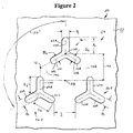
- Figure 2 is a view of the bottom surface of a spinneret plate having a cluster of orifices formed therein for producing the filament shown in Figure 1;
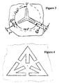
- Figure 3 is a view of the bottom surface of a spinneret plate used for spinning the filaments of Comparative Example 1; and
- Figure 4 is a view of the bottom surface of a spinneret plate used for spinning the filaments of Comparative Example 2.
-
- Throughout the following detailed description similar reference numerals refer to similar elements in all Figures of the drawings.
- Figure 1 is a cross section view of a bulked continuous filament generally indicated by
reference character 10 in accordance with the present invention. Alongitudinal axis 12 extending through thefilament 10 serves its geometric center. The distance from theaxis 12 to the point(s) on the exterior contour of thefilament 10 closest to the axis defines the minor radius (R1) of the filament. A major radius (R2) is defines the distance from theaxis 12 to the point(s) on the exterior contour of the filament that lie farthest therefrom. - Each
filament 10 has a generally three-sided exterior configuration formed from sides 14A, 14B and 14C. The side 14A is defined by a smoothly curved contour extending between a firstrounded tip 16A and a secondrounded tip 16B. The side 14B is defined by a smoothly curved contour extending between the secondrounded tip 16B and a third rounded tip 16C. The side 14C is defined by a smoothly curved contour extending between the thirdrounded tip 16B and the roundedfirst tip 16A. The distance from a respective center of generation 18A, 18B, 18C to eachrounded tip - Each exterior side 14A, 14B, 14C has a first inwardly extending
depressed region 22 disposed near one tip and a second inwardly extendingdepressed region 24 disposed near the other tip. By "depressed region" it is meant that the contour of the filament in that region extends inwardly toward theaxis 12 of the filament. Theintermediate region 26 of each side 14A, 14B, 14C (i.e., the region between thedepressed regions axis 12. Each exterior side 14A, 14B, 14C of thefilament 10 thus exhibits a generally "wavy" configuration having two concave regions (i.e., thedepressed regions 22, 24) and three convex regions (i.e., the bowedintermediate region 26 and therounded regions 28 disposed near each rounded tip of each side). - In general a
filament 10 in accordance with the present invention has an exterior modification ratio (R2/R1) in the range from about 1.4 to about 2.0, and more particularly in the range from about 1.6 to about 1.8. In addition, the ratio of the major radius (R2) to the tip radius (R3) defines a tip ratio (R2/R3) in the range from about 2.0 to about 4.0, and more particularly in the range from about 2.0 to about 3.0. - The
filament 10 has avoid 30 extending centrally and axially therethrough. Theaxis 12 defines the geometric center of the void. Thecentral void 30 is a generally "delta-shaped" opening having three generally convexmajor sides 32A, 32B, 32C. Adjacent pairs ofmajor sides 32A, 32B, 32C join at adjacent ends to define threemajor apices 34A, 34B, 34C. In accordance with the present invention eachside 32A, 32B, 32C is itself configured from a pair ofdiscernable facets facets facets minor apex major side 32A, 32B, 32C. Themajor apices 34A, 34B, 34C lie a distance RM from thegeometric center 12 of thevoid 30 while theminor apices - The
void 30 may occupy from about four percent (4%) to about twenty-five percent (25%), and more particularly from about four percent (4%) to about fifteen percent (15%), of the cross sectional area of thefilament 10. - In accordance with the present invention the
central void 30 is oriented within thefilament 10 such that eachmajor apex 34A, 34B, 34C of thevoid 30 extends toward the approximate midpoint of the respective proximal side 14A, 14B, 14C of thefilament 10, while eachminor apex rounded tip - These relationships are exemplified in Figure 1 by the
radial reference line 42 extending from theaxis 12 of thefilament 10 through the major apex 34C and apoint 44 disposed substantially midway along theintermediate region 26 of the side 14C. Similar reference lines, omitted for clarity, may be drawn through the othermajor apices 34A, 34B and a substantial midpoint of the intermediate region on the respective proximal sides 14A, 14B of the exterior of thefilament 10. The alignment of the minor apices and the rounded tip of the filament is exemplified in Figure 1 by aradial reference line 46 extending from theaxis 12 of thefilament 10 through the minor apex 40C and the rounded tip 16C of the filament. Similar reference lines, again omitted for clarity, may be drawn through theminor apices rounded tips - A filament in accordance with the present invention is a bulked continuous filament prepared using a synthetic, thermoplastic melt-spinnable polymer. Suitable polymers include polyamides, polyesters, and polyolefins. The polymer is first melted and then is extruded ("spun") through a
spinneret plate 50 having appropriately sized orifices therein (to be described hereinafter) under conditions which vary depending upon the individual polymer thereby to produce afilament 10 having the desired denier, exterior modification ratio, tip ratio, apex ratio and void percentage. The filaments are subsequently quenched by air flowing across them at a flow rate of between 1.2 - 1.8 ft/sec (0.36 to 0.55 m/sec). Void percentage can be increased by more rapid quenching and increasing the melt viscosity of thermoplastic melt polymers, which can slow the flow allowing sturdy pronounced molding to occur. - A plurality of
filaments 10 are gathered together to form a yarn. Drawing and bulking of the combined filaments is performed by any method known in the art, with the preferred operating condition described below in the examples provided. - Owing to the particular desired properties of the filaments 10 a yarn formed therefrom is believed to be particularly advantageous for tufting [with other types of yarn(s), if desired] into carpet having especially desirable properties. If desired, the yarn could include other forms of filament(s).
- Figure 2 illustrates a
spinneret plate 50 useful for producing afilament 10 in accordance with the invention. - The
spinneret plate 50 is a relatively massive member having an upper surface (not shown) and a bottom surface 52. As is well appreciated by those skilled in the art a portion of the upper surface of the spinneret plate is provided with a bore recess (not shown) whereby theplate 50 is connected to a source of polymer. Depending upon the rheology of the polymer being extruded the lower margins of the bore recess may be inclined to facilitate flow of polymer from the supply to the spinneret plate. - A plurality of capillary openings each generally indicated by the
reference character 54 extends through theplate 50 from the recessed upper surface to the bottom surface 52. Eachcapillary opening 54 serves to form one filament. Only onesuch capillary opening 54 is illustrated in Figure 2. The number of capillary openings provided in a given plate thus corresponds to the number of filaments being gathered to form a predetermined number of yarn(s). As noted, additional filaments (if used) may be incorporated into the yarn in any convenient manner. - As best seen in Figure 2, in the present invention each
capillary opening 54 is itself defined by a cluster of three orifices 56-1, 56-2 and 56-3 centered symmetrically about acentral point 58. - Each orifice 56-1, 56-2 and 56-3 is a generally "Y"-shaped opening comprising three
linear legs leg longitudinal axis axes axes legs junction point 68. The junction points 68 are spaced adistance 70 from thecenter point 58 of the cluster. - The orifices 56-1, 56-2 and 56-3 are arranged with respect to each other such that one leg of each orifice 56-1, 56-2 and 56-3, e.g., the
leg 62A, extends from thejunction point 68 in a radially outward direction relative to thecentral point 58. Stated alternatively, the radially outwardly extendingleg 62A of each orifice 56-1, 56-2 and 56-3 is oriented such that itsaxis 64A aligns with aradius 70 extending outwardly from thecentral point 58. Eachjunction point 68 of the orifices 56-1, 56-2, 56-3 respectively corresponds to amajor apex 34A, 34B, 34C of thevoid 30 of the filament being spun. - The other two
legs 62B, 62C of each orifice 56-1, 56-2 and 56-3 are arranged such that theaxes apex point 72 disposed intermediate adjacent orifices. Extensions of each of theaxes legs 62B, 62C intersect at anapex point 72. Eachapex point 72 corresponds to a respectiveminor apex void 30 of the filament being spun. The ends of the confrontinglegs 62B, 62C are spaced from each other by agap gaps legs legs - The width dimensions of the
legs radially extending leg 62A (indicated by the reference character B1) is wider than the width dimensions (indicated by the reference characters B2, B3) of theother legs 62B, 62C. - The spinneret plate may be fabricated in any appropriate manner, as by using the laser technique disclosed in United States Patent 5,168,143, (Kobsa et al., QP-4171-A), assigned to the assignee of the present invention.
- The following Table presents the magnitudes of the various dimensions A1, A2, A3, B1, B2, B3, and C used to fabricate filaments having the cross section illustrated in Figure 1 used in invention Example 1 and Invention Example 2. The dimensions are in inches, with the corresponding metric measurement given parenthetically in centimeters.
A1, A2, A3 B1 B2, B3 C Figure 1A 0.0153 0.0073 0.0061 0.0186 (Invention Example 1) (0.0389) (0.019) (0.015) (0.047) Figure 1 B 0.0214 0.0052 0.0044 0.0247 (Invention Example 2) (0.054) (0.013) (0.011) (0.062) - Trilobal cross sections with voids (hollow filament) have been practiced in the past [e.g., United States Patent 6,048,615 (Lin)]. However, hollow filament yarns are difficult to make because of cross section shape control. Void percent and exterior modification ratio are both sensitive to polymer viscosity and quench air flow. As is well understood by one skilled in the art, without tight control of these parameters, lack of cross section shape uniformity can result in streaks when the yarns are finally tufted into a carpet.
- The combination of the three orifices taken together with the enlarged width dimension (B1) of the radially outwardly extending leg of each orifice causes polymer streams emanating from each orifice to converge, thus producing surprisingly stable polymer flow that is less prone to filament breakage and process interruption than the more complicated spinnerets of the prior art.
- The stable polymer flow provided by the use of the spinneret in accordance also results in surprising robustness of cross section formation in the spinning process. The fiber cross section shape is measurably less sensitive to quench airflow, and thus provides a distinct advantage versus the prior art as a result of the greater consistency of shape provided along the length of the formed filaments and yarns made therefrom.
- In addition, the disclosed spinneret plate is especially useful in the manner of producing the disclosed filament cross-section because it is simpler and less expensive to produce than previous hollow filament spinnerets.
- Nylon 6,6 filaments having various cross-sections were produced for Comparative Examples A and B and for Invention Examples 1 and 2 from appropriately configured spinnerets, each with one hundred thirty-six (136) capillaries.
- The nylon 6,6 polymer used for all of the examples was a bright polymer. The polymer spin dope did not contain any delusterant and had a relative viscosity (RV) of sixty-eight plus/minus approximately three units (68, +/- ~3 units). The polymer temperature before the spinning pack was controlled at about two hundred ninety plus/minus one degree Centigrade (290, +/- 1°C). The spinning throughput was seventy pounds (70 Ibs; 31.8 kg) per hour.
- The relative viscosity (RV) was measured by dissolving 5.5 grams of nylon 6,6 polymer in fifty cubic centimeters (50 cc) of formic acid. The RV is the ratio of the absolute viscosity of the nylon 66/formic acid solution to the absolute viscosity of the formic acid. Both absolute viscosities were measured at twenty-five degrees Centigrade (25 °C).
- The polymer was extruded through the different spinnerets and divided into two (2) sixty-eight filament (68) segments. The capillary dimensions for the spinnerets are described below. The molten fibers were then rapidly quenched in a chimney, where cooling air at about nine degrees Centigrade (~9 °C) was blown past the filaments at three hundred cubic feet per minute [300 cfm (732 m/min)] through the quench zone. The filaments were then coated with a lubricant for drawing and crimping. The coated yarns were drawn at 2197 yards per minute (2.75 x draw ratio) using a pair of heated draw rolls. The draw roll temperature was one hundred ninety degrees Centigrade (190°C). The filaments were then forwarded into a dual-impingement hot air bulking jet similar to that described in Coon, U.S. Patent 3,525,134 (Coon, assigned to the assignee of the present invention) to form two (2) twelve hundred five denier (1205 denier, 1340 decitex), 17.7 denier per filament (dpf) yarns (19 decitex per filament). The temperature of the air in the bulking jet was two hundred twenty degrees Centigrade (220 °C).
- The spun, drawn, and crimped bulked continuous filament (BCF) yarns were cable-twisted to 3.2 turns per inch (tpi) on a cable twister and heat-set on a Superba heat-setting machine at setting temperature of two hundredt sixty degrees Farenheit (265 °F; 129.4°C).
- The yarns were then tufted into twenty-eight ounce per square yard (28 oz/sq.yd; 949 g/sq. meter) having 0.21875 inch [7/32", 0.56 cm] pile height loop pile carpets on a 1/10 inch gauge (0.254 cm) loop pile tufting machine. The tufted carpets were dyed on a continuous range dyer into medium yellow carpets.
- Each carpet sample produced from the yarns of Comparative Examples A and B and Invention Examples 1 and 2 was subjected to the following tests.
- Carpet Glitter and Bulk Ratings. The degrees of bulk and glitter for different cut-pile carpet samples were visually compared in a side-by side comparison without knowledge of which carpets were made with which yarns. The carpets were examined by a panel of five (5) experienced examiners each familiar with carpet construction and surface texture. The glitter value was measured by the examiners on a scale of "1" to "5", with "5" being the most glitter. The glitter rating for each sample was averaged and the samples given a rating of low, medium or high glitter based on the average rating. Carpet bulk was rated in the same manner. The glitter and bulk results are reported in Table 2.
- Soiling Test The soiling test was conducted on each carpet sample using a Vetterman drum.
- The base color of the sample was measured using the hand held color measurement instrument sold by Minolta Corporation as "Chromameter" model CR-210. This measurement was the control value.
- The carpet sample was placed in Vetterman drum. Two hundred grams (200 g) of clean nylon 101 Zytel nylon beads and fifty grams (50 g) of dirty beads (by DuPont Canada, Mississauga, Ontario) were placed on the sample. The dirty beads were prepared by mixing ten grams (10 g) of AATCC TM-122 synthetic carpet soil (by Manufacturer Textile Innovators Corp. Windsor, N.C.) with one thousand grams (1000 g) of new Nylon 101 Zytel beads. Sixteen to seventeen hundred grams (1600-1700 g) of ceramic cylindrical shaped beads [110 to 130 1/2" diameter x ½" length small beads and twenty-five to thirty-five (25 to 35) ¾" diameter, ¾" length (1.91 cm diameter, 1.91 cm length) large beads were added into the Vetterman drum. The Vetterman drum was run for five hundred (500) cycles and the sample removed.
- The color of the sample was again measured and the color change versus the control value (delta E) owing to soiling was recorded as an "As Soiled" value [note: This interim result is not reported in Table 2]. The sample was vacuumed four (4) times in both the length and width directions and the color was again measured and the color change versus control value (delta E) after vacuuming was recorded as an "As Cleaned" value [note: This interim result is not reported in Table 2].
- The sample was placed back in the drum, fifty grams (50 g) of soiled bead mixture was discarded and fifty grams (50 g) of new dirty beads were added into the drum.
- The procedure described above was repeated for three additional five hundred (500) cycle runs.
- After a total of two thousand (2000) cycles, the color of the sample versus the control value (delta E) "As Soiled" was measured and reported. The color change versus the control value after vacuuming (the "As Cleaned" value) was measured and recorded. These measurements (i.e., the "As Soiled" and the "As Cleaned" values taken after two thousand cycles) are reported in Table 2 in the columns "As Soiled" and "As Cleaned", respectively. Samples with a high value of delta E perform worse than samples with low delta E value.
- Filaments having a trilobal cross-section as disclosed in U.S. Patent 4,492,731 (Bankar et al.), assigned to the assignee of the present invention, were made using the above-described spinning process. The filaments were spun through a spinneret capillary as shown in Figure 3 having three tapered arms (lobes) which were essentially symmetrical.
- Filaments having a hollow trilobal cross section as disclosed in U.S. Patent 6,048,615 (Lin), assigned to the assignee of the present invention, were made using the above-described spinning process. The filaments were spun through a spinneret capillary as shown in Figure 4.
- Filaments having a hollow trilobal cross section as described by this invention, as shown in Figure 1B, were made using the above-described process. The filaments were spun through a spinneret capillary as shown in Figure 2. The dimensions A1, A2, A3, B1, B2, B3, C used to produce Invention Example 1 are as set forth in Table 1.
- The filament had an exterior modification ratio of 1.66, a tip ratio of 2.6, an apex ratio of 1.08. The central void occupied about 5.3 percent of the cross sectional area of the filament.
- Filaments having a hollow trilobal cross section as described by this invention, as shown in Figure 1C were made using the above-described process. The filaments were spun through a spinneret capillary as shown in Figure 2. The dimensions A1, A2, A3, B1, B2, B3, C used to produce Invention Example 2 are as set forth in Table 1.
- The filament had an exterior modification ratio of 1.88, a tip ratio of 3.5, an apex ratio of 1.33. The central void occupied about ten percent (10%) of the cross sectional area of the filament.
- The test results are summarized below in Table 2.
Example Cross-section (exterior MR) Soiling (ΔE) As Soiled Soiling (ΔE) Cleaned Glitter Bulk Comp. A Solid trilobal (2.6 MR) 23.25 21.14 High High Comp. B Hollow trilobal (-.- MR) N/A N/A High Medium Inv.1 1.66 17.94 16.71 Low Medium Inv.2 1.88 21.17 19.86 Low High - As can be appreciated from Table 2, Examples 1 and 2 (having relatively "wavy" sides including two concave and three convex surfaces and a void shaped and oriented in the manner shown in Figure 1) demonstrate distinctly different and lower "Glitter" in the final carpet than do Comparative Examples A and B. The filament and yarn of the present invention is useful as a carpet yarn having more "wool-like" appearance when made into carpet than yarns of the prior art having similar bulk, soiling and cleaning characteristics.
- The filament of the invention is also smoother (i.e., with rounded tips and without sharply defined cusps) and therefore less prone to soiling than other known high bulk trilobal fibers that can otherwise impart similar aesthetics to a carpet made therefrom, as is clearly supported by the soiling data in Table 2. A carpet constructed from yarn of the present invention therefore retains its appearance longer in service than carpets made from yarn of the prior art.
- To achieve high bulk with low glitter is generally believed to be difficult. The invention provides a surprisingly low glitter yarn that can produce carpets of comparable bulk to carpets made from such high glitter yarns as the solid trilobal cross section filaments(Comparative Example A).
- As a result of the configuration filaments in accordance with this invention and yarns formed therefrom are easily bulked and exhibit a relatively low glitter while the exterior contour resists soil accumulation.
Claims (2)
- A spinneret plate for producing a synthetic polymer filament having an exterior configuration with three sides with each side of the filament defining a smoothly curved contour extending between a first and a second end, each side of the filament having an inwardly extending depressed region being disposed adjacent to each end of each side,
the filament having a generally delta-shaped void extending centrally and axially therethrough, the void having a geometric center and three major apices, each side of the void being convex in shape and having a first and a second end, each side of the void being formed from two facets that meet to define a minor apex intermediate the first and second end of each side,
the spinneret plate having a cluster of three Y-shaped orifices centered about a central point, each Y-shaped orifice having a three linear legs joined at a junction point corresponding to a major apex of the void,
each leg having an axis therethrough, one leg of each orifice extending radially outwardly from the junction point, the axis of the radially outwardly extending leg aligning with a radius extending outwardly from the central point,
the axes of each of the other two legs of each orifice projecting toward a point disposed intermediate adjacent orifices, each intermediate point corresponding to a minor apex of the void. - The spinneret plate of claim 1 wherein the radially outwardly extending leg of each of the Y-shaped orifices is wider than the other legs of the Y-shaped orifice.
Applications Claiming Priority (2)
| Application Number | Priority Date | Filing Date | Title |
|---|---|---|---|
| US52387103P | 2003-11-19 | 2003-11-19 | |
| US523871P | 2003-11-19 |
Publications (1)
| Publication Number | Publication Date |
|---|---|
| EP1541724A1 true EP1541724A1 (en) | 2005-06-15 |
Family
ID=34520265
Family Applications (1)
| Application Number | Title | Priority Date | Filing Date |
|---|---|---|---|
| EP04257171A Withdrawn EP1541724A1 (en) | 2003-11-19 | 2004-11-19 | Spinneret plate for producing a bulked continuous filament having a three-sided exterior cross-section and a convex six-sided central void |
Country Status (1)
| Country | Link |
|---|---|
| EP (1) | EP1541724A1 (en) |
Cited By (1)
| Publication number | Priority date | Publication date | Assignee | Title |
|---|---|---|---|---|
| CN103225118A (en) * | 2013-03-27 | 2013-07-31 | 嘉兴学院 | Side by side composite fiber spinneret plate, method of preparing three-dimensional crimp antibacterial fiber with spinneret plate and application of three-dimensional crimp antibacterial fiber |
Citations (5)
| Publication number | Priority date | Publication date | Assignee | Title |
|---|---|---|---|---|
| GB1099258A (en) * | 1965-10-21 | 1968-01-17 | Inventa Ag | Spinning plate used for melt-spinning hollow profile synthetic fibres |
| EP0516119A2 (en) * | 1991-05-31 | 1992-12-02 | Basf Corporation | Hollow trilobal cross-section filament and spinneret plate for the manufacture of it |
| JPH05287632A (en) * | 1992-04-02 | 1993-11-02 | Toray Ind Inc | Hollow crimped yarn |
| WO1994013869A1 (en) * | 1992-12-08 | 1994-06-23 | Basf Corporation | Hollow trilobal cross section fiber |
| WO1999039029A1 (en) * | 1998-01-30 | 1999-08-05 | E.I. Du Pont De Nemours And Company | Filament having a trilobal cross section and a trilobal void |
-
2004
- 2004-11-19 EP EP04257171A patent/EP1541724A1/en not_active Withdrawn
Patent Citations (6)
| Publication number | Priority date | Publication date | Assignee | Title |
|---|---|---|---|---|
| GB1099258A (en) * | 1965-10-21 | 1968-01-17 | Inventa Ag | Spinning plate used for melt-spinning hollow profile synthetic fibres |
| EP0516119A2 (en) * | 1991-05-31 | 1992-12-02 | Basf Corporation | Hollow trilobal cross-section filament and spinneret plate for the manufacture of it |
| JPH05287632A (en) * | 1992-04-02 | 1993-11-02 | Toray Ind Inc | Hollow crimped yarn |
| WO1994013869A1 (en) * | 1992-12-08 | 1994-06-23 | Basf Corporation | Hollow trilobal cross section fiber |
| WO1999039029A1 (en) * | 1998-01-30 | 1999-08-05 | E.I. Du Pont De Nemours And Company | Filament having a trilobal cross section and a trilobal void |
| US6048615A (en) * | 1998-01-30 | 2000-04-11 | E. I. Du Pont De Nemours And Company | Filament having a trilobal cross-section and a trilobal void |
Non-Patent Citations (1)
| Title |
|---|
| PATENT ABSTRACTS OF JAPAN vol. 018, no. 082 (C - 1164) 10 February 1994 (1994-02-10) * |
Cited By (2)
| Publication number | Priority date | Publication date | Assignee | Title |
|---|---|---|---|---|
| CN103225118A (en) * | 2013-03-27 | 2013-07-31 | 嘉兴学院 | Side by side composite fiber spinneret plate, method of preparing three-dimensional crimp antibacterial fiber with spinneret plate and application of three-dimensional crimp antibacterial fiber |
| CN103225118B (en) * | 2013-03-27 | 2015-07-15 | 嘉兴学院 | Side by side composite fiber spinneret plate, method of preparing three-dimensional crimp antibacterial fiber with spinneret plate and application of three-dimensional crimp antibacterial fiber |
Similar Documents
| Publication | Publication Date | Title |
|---|---|---|
| CA2138687C (en) | Trilobal and tetralobal cross-section filaments containing voids | |
| EP1966416B1 (en) | Hexalobal cross-section filaments with three major lobes and three minor lobes, carpet tufted from yarn with such filaments, and capillary spinneret orifice for producing such filaments | |
| US4492731A (en) | Trilobal filaments exhibiting high bulk and sparkle | |
| US10017880B2 (en) | Bulked continuous filaments with trilobal cross-section and round central void and spinneret plates producing filament | |
| US4020229A (en) | Multi-cavity filaments | |
| CA2314172A1 (en) | Filament having a trilobal cross-section and a trilobal void | |
| US7087303B2 (en) | Bulked continuous filament having a three-sided exterior cross-section and convex six-sided central void and yarn and carpet produced therefrom | |
| CA2220460C (en) | Filament having a triangular cross-section and 3 or 6 axially extending voids | |
| US20060008548A1 (en) | Spinneret plate for producing a bulked continuous filament having a three-sided exterior cross-section and a convex six-sided central void | |
| US6939608B2 (en) | Bulked continuous filament having a three-sided exterior cross-section and a convex six-sided central void and yarn and carpet produced therefrom | |
| US5447771A (en) | Fiber bilobal cross-sections and carpets prepared therefrom having a silk-like luster and soft hand | |
| US20050147788A1 (en) | Spinneret plate for producing a bulked continuous filament having a three-sided exterior cross-section and a convex six-sided central void | |
| US6589653B2 (en) | Filament having a quadrilobate exterior cross-section and a four-sided void | |
| US20110281057A1 (en) | Bulked continuous filaments with hexalobal cross-section and three voids and spinneret plates for producing the filament | |
| EP1541725B1 (en) | Bulked continuous filament having a three-sided exterior cross-section and a convex six-sided central void and yarn and carpet produced therefrom | |
| US3734993A (en) | Method for extruding t-shaped filaments | |
| MX2008006928A (en) | Hexalobal cross-section filaments with three major lobes and three minor lobes, carpet tufted from yarn with such filaments, and capillary spinneret orifice for producing such filaments |
Legal Events
| Date | Code | Title | Description |
|---|---|---|---|
| PUAI | Public reference made under article 153(3) epc to a published international application that has entered the european phase |
Free format text: ORIGINAL CODE: 0009012 |
|
| AK | Designated contracting states |
Kind code of ref document: A1 Designated state(s): AT BE BG CH CY CZ DE DK EE ES FI FR GB GR HU IE IS IT LI LU MC NL PL PT RO SE SI SK TR |
|
| AX | Request for extension of the european patent |
Extension state: AL HR LT LV MK YU |
|
| RIN1 | Information on inventor provided before grant (corrected) |
Inventor name: TUNG, WAE-HAI |
|
| 111Z | Information provided on other rights and legal means of execution |
Free format text: ATBEBGCHCYCZDEDKEEESFIFRGBGRHUIEISITLUMCNLPLPTROSESISKTR Effective date: 20050823 |
|
| 17P | Request for examination filed |
Effective date: 20051123 |
|
| AKX | Designation fees paid |
Designated state(s): AT BE BG CH CY CZ DE DK EE ES FI FR GB GR HU IE IS IT LI LU MC NL PL PT RO SE SI SK TR |
|
| STAA | Information on the status of an ep patent application or granted ep patent |
Free format text: STATUS: THE APPLICATION HAS BEEN WITHDRAWN |
|
| 18W | Application withdrawn |
Effective date: 20070524 |