EP1541704A1 - Process for producing aluminum material for electrolytic capacitor electrode, aluminum material for electrolytic capacitor electrode and electrolytic capacitor - Google Patents
Process for producing aluminum material for electrolytic capacitor electrode, aluminum material for electrolytic capacitor electrode and electrolytic capacitor Download PDFInfo
- Publication number
- EP1541704A1 EP1541704A1 EP03741124A EP03741124A EP1541704A1 EP 1541704 A1 EP1541704 A1 EP 1541704A1 EP 03741124 A EP03741124 A EP 03741124A EP 03741124 A EP03741124 A EP 03741124A EP 1541704 A1 EP1541704 A1 EP 1541704A1
- Authority
- EP
- European Patent Office
- Prior art keywords
- aluminum material
- electrolytic capacitor
- tensile strain
- capacitor electrodes
- bridle roll
- Prior art date
- Legal status (The legal status is an assumption and is not a legal conclusion. Google has not performed a legal analysis and makes no representation as to the accuracy of the status listed.)
- Granted
Links
Images
Classifications
-
- H—ELECTRICITY
- H01—ELECTRIC ELEMENTS
- H01G—CAPACITORS; CAPACITORS, RECTIFIERS, DETECTORS, SWITCHING DEVICES, LIGHT-SENSITIVE OR TEMPERATURE-SENSITIVE DEVICES OF THE ELECTROLYTIC TYPE
- H01G9/00—Electrolytic capacitors, rectifiers, detectors, switching devices, light-sensitive or temperature-sensitive devices; Processes of their manufacture
- H01G9/004—Details
- H01G9/04—Electrodes or formation of dielectric layers thereon
- H01G9/042—Electrodes or formation of dielectric layers thereon characterised by the material
- H01G9/045—Electrodes or formation of dielectric layers thereon characterised by the material based on aluminium
-
- B—PERFORMING OPERATIONS; TRANSPORTING
- B21—MECHANICAL METAL-WORKING WITHOUT ESSENTIALLY REMOVING MATERIAL; PUNCHING METAL
- B21D—WORKING OR PROCESSING OF SHEET METAL OR METAL TUBES, RODS OR PROFILES WITHOUT ESSENTIALLY REMOVING MATERIAL; PUNCHING METAL
- B21D1/00—Straightening, restoring form or removing local distortions of sheet metal or specific articles made therefrom; Stretching sheet metal combined with rolling
- B21D1/05—Stretching combined with rolling
-
- C—CHEMISTRY; METALLURGY
- C22—METALLURGY; FERROUS OR NON-FERROUS ALLOYS; TREATMENT OF ALLOYS OR NON-FERROUS METALS
- C22F—CHANGING THE PHYSICAL STRUCTURE OF NON-FERROUS METALS AND NON-FERROUS ALLOYS
- C22F1/00—Changing the physical structure of non-ferrous metals or alloys by heat treatment or by hot or cold working
- C22F1/04—Changing the physical structure of non-ferrous metals or alloys by heat treatment or by hot or cold working of aluminium or alloys based thereon
-
- B—PERFORMING OPERATIONS; TRANSPORTING
- B21—MECHANICAL METAL-WORKING WITHOUT ESSENTIALLY REMOVING MATERIAL; PUNCHING METAL
- B21B—ROLLING OF METAL
- B21B3/00—Rolling materials of special alloys so far as the composition of the alloy requires or permits special rolling methods or sequences ; Rolling of aluminium, copper, zinc or other non-ferrous metals
- B21B2003/001—Aluminium or its alloys
-
- B—PERFORMING OPERATIONS; TRANSPORTING
- B21—MECHANICAL METAL-WORKING WITHOUT ESSENTIALLY REMOVING MATERIAL; PUNCHING METAL
- B21B—ROLLING OF METAL
- B21B15/00—Arrangements for performing additional metal-working operations specially combined with or arranged in, or specially adapted for use in connection with, metal-rolling mills
- B21B2015/0071—Levelling the rolled product
-
- B—PERFORMING OPERATIONS; TRANSPORTING
- B21—MECHANICAL METAL-WORKING WITHOUT ESSENTIALLY REMOVING MATERIAL; PUNCHING METAL
- B21B—ROLLING OF METAL
- B21B39/00—Arrangements for moving, supporting, or positioning work, or controlling its movement, combined with or arranged in, or specially adapted for use in connection with, metal-rolling mills
- B21B39/02—Feeding or supporting work; Braking or tensioning arrangements, e.g. threading arrangements
- B21B39/08—Braking or tensioning arrangements
-
- B—PERFORMING OPERATIONS; TRANSPORTING
- B21—MECHANICAL METAL-WORKING WITHOUT ESSENTIALLY REMOVING MATERIAL; PUNCHING METAL
- B21B—ROLLING OF METAL
- B21B45/00—Devices for surface or other treatment of work, specially combined with or arranged in, or specially adapted for use in connection with, metal-rolling mills
- B21B45/004—Heating the product
-
- C—CHEMISTRY; METALLURGY
- C21—METALLURGY OF IRON
- C21D—MODIFYING THE PHYSICAL STRUCTURE OF FERROUS METALS; GENERAL DEVICES FOR HEAT TREATMENT OF FERROUS OR NON-FERROUS METALS OR ALLOYS; MAKING METAL MALLEABLE, e.g. BY DECARBURISATION OR TEMPERING
- C21D8/00—Modifying the physical properties of ferrous metals or ferrous alloys by deformation combined with, or followed by, heat treatment
- C21D8/02—Modifying the physical properties of ferrous metals or ferrous alloys by deformation combined with, or followed by, heat treatment during manufacturing of plates or strips
- C21D8/0247—Modifying the physical properties of ferrous metals or ferrous alloys by deformation combined with, or followed by, heat treatment during manufacturing of plates or strips characterised by the heat treatment
- C21D8/0252—Modifying the physical properties of ferrous metals or ferrous alloys by deformation combined with, or followed by, heat treatment during manufacturing of plates or strips characterised by the heat treatment with application of tension
-
- C—CHEMISTRY; METALLURGY
- C21—METALLURGY OF IRON
- C21D—MODIFYING THE PHYSICAL STRUCTURE OF FERROUS METALS; GENERAL DEVICES FOR HEAT TREATMENT OF FERROUS OR NON-FERROUS METALS OR ALLOYS; MAKING METAL MALLEABLE, e.g. BY DECARBURISATION OR TEMPERING
- C21D9/00—Heat treatment, e.g. annealing, hardening, quenching or tempering, adapted for particular articles; Furnaces therefor
- C21D9/52—Heat treatment, e.g. annealing, hardening, quenching or tempering, adapted for particular articles; Furnaces therefor for wires; for strips ; for rods of unlimited length
- C21D9/54—Furnaces for treating strips or wire
- C21D9/56—Continuous furnaces for strip or wire
- C21D9/562—Details
- C21D9/564—Tension control
Definitions
- the present invention relates to a method for manufacturing aluminum material for electrolytic capacitor electrodes, aluminum material manufactured by the method, and an electrolytic capacitor using the aluminum material.
- aluminum is used to include the meaning of aluminum and its alloy, and "aluminum material” includes at least an aluminum foil, an aluminum plate and a formed article thereof.
- aluminum material for electrolytic capacitor electrodes e.g. , anode material for use in electrolytic capacitors for middle and high voltage
- anode material for use in electrolytic capacitors for middle and high voltage is manufactured by subjecting an aluminum ingot with aluminum purity of 99.8 % or more to hot rolling, first cold rolling, intermediate annealing, second cold rolling and final annealing in this order.
- This anode material for electrolytic capacitors for middle and high voltage is subjected to electrolytic etching to form tunnel-like pits and then subjected it to chemical forming. Accordingly, in order to obtain anode material with high capacitance, aluminum material should be good in etching properties. Therefore, it has been attempted to improve the etching properties from various points of view.
- Patent document 1 Japanese Examined Laid-open Patent Publication No. S54-11242 discloses a method for obtaining aluminum material with high area fraction of cube orientation. In this method, after first cold rolling at a high cold rolling rate of curing of 1,000% or more, a material is subjected to intermediate annealing at 180 to 350 °C. then to second cold rolling at a rolling reduction of 5 to 35%, and thereafter subjected to final annealing to thereby obtain aluminum material with high area fraction of cube orientation.
- Patent document 2 Japanese Unexamined Laid-open Patent Publication No. H06-145923 discloses a method for obtaining aluminum material with high area fraction of cube orientation.
- a material is subjected to intermediate annealing, then to second cold rolling at a rolling reduction of 10 to 40%, wherein between the steps from the initiation of the second cold rolling to the initiation of the final annealing the tensile strain is adjusted so as to fall within the range of 0.2 to 5.0% to thereby obtain aluminum material with high area fraction of cube orientation.
- the texture is controlled by carrying out second cold rolling at a low rolling reduction after intermediate annealing to thereby increase the area fraction of cube orientation.
- aluminum material for electrolytic capacitor anodes aluminum material having a thickness of about 100 ⁇ m is used. Therefore, in order to obtain high capacitance by increasing a thickness, it is necessary to develop material having a thickness exceeding 100 ⁇ m.
- some embodiments can provide a method for manufacturing aluminum material having high area fraction of cube orientation by simplified steps.
- some embodiments can provide aluminum material manufactured by the aforementioned method.
- some embodiments can provide an electrolytic capacitor using the aforementioned aluminum material.
- some embodiments can provide a method for manufacturing aluminum material for use in electrolytic capacitor electrodes in which the area fraction of cube orientation is high without coarsened grains by a method different from the aforementioned conventional methods.
- some embodiments can provide aluminum material manufactured by the aforementioned method.
- some embodiments can provide an electrolytic capacitor using the aforementioned aluminum material.
- a method for manufacturing aluminum material for use in electrolytic capacitor electrodes has the following structure as recited in the following Items (1) to (17).
- peripheral speeds P1 and Po meet a relation of 0 ⁇ (Po-Pi)/Pi ⁇ 0.1, predetermined tensile strain can be applied without causing any scratches or breaking of aluminum material.
- the peripheral speed difference can be generated by driving bridle rolls of the upstream-side bridle roll unit and those of the downstream-side bridle roll unit at different rotational speeds.
- the peripheral speed difference can be generated by employing bridle rolls of the downstream-side bridle roll unit with a larger bridle roll diameter than a bridle roll diameter of bridle rolls of the upstream-side bridle roll unit.
- the tensile stain can be applied at two positions or more in one pass for applying the tensile strain.
- the pass for applying the tensile strain can be carried out a plurality of times.
- a tension leveling device can be used as the tensile strain application equipment. In this case, leveling of shape defects such as flatness and an application of tensile strain can be performed.
- the aluminum material can be manufactured efficiently.
- the aluminum material can be manufactured efficiently.
- An electrolytic capacitor in which the aluminum material manufactured in accordance with the present invention can have large capacitance.
- an application of tensile strain of 1% or more is preferable to obtain a higher area fraction of cube orientation.
- an application of excessive tensile strain may cause breaking of aluminum material, and therefore an application of tensile strain of 15% or less is preferable. It is preferable to apply tensile strain by 3 to 12%, more preferably exceeding 5% but not exceeding 10%.
- the aluminum material to which tensile strain is given is subjected to final annealing. This causes growth of cube-oriented grains, and a high area fraction of cube orientation can be obtained eventually.
- a method for applying tensile strain is not specifically limited.
- the following method can be exemplified.
- aluminum material wound on an unwinding coil is wound on a winding coil by unwinding the aluminum material from the unwinding coil while applying brake to the unwinding coil to thereby apply tensile strength to the aluminum material between the unwinding coil and the winding coil.
- the application of tensile strength can be performed by one-axis tension in which tensile strength is applied to the aluminum material only in one direction, e.g., in a longitudinal direction, or two-axis tension in which tensile strength is applied to the aluminum material in different two directions, for example, in the longitudinal direction and the widthwise direction.
- the application of tensile strain can be performed by bending the aluminum material.
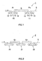
- Fig. 1 is a schematic view showing an embodiment of the tensile strain application equipment. A method for applying tensile strain using this device will be detailed as follows.
- the tensile strain application equipment 1 has two bridle roll units, or an upstream side bridle roll unit 10 and a downstream side bridle roll unit 11 disposed at the upstream side and downstream side in the transferring direction of the aluminum material S respectively.
- a tension applying area Q is formed between the two bridle roll units 10 and 11.
- the peripheral speed Pi in the upstream side bridle roll unit 10 and the peripheral speed Po in the downstream side bridle roll unit 11 are set to be Pi ⁇ Po. This peripheral speed difference causes continuous plastic strain of the aluminum material S at the tension applying area Q, which applies tensile strain to the aluminum material S.
- the upstream side bridle roll unit 10 and the downstream side bridle roll unit 11 are constituted by four bridle rolls 12, 12, 12, 12 and 13, 13, 13, 13, respectively, the number of rolls and the layout of rolls are not limited to this embodiment and can be set arbitrary.
- the aforementioned peripheral speed Pi, Po meets the relation of 0 ⁇ (Po-Pi)/Pi ⁇ 0.1, more preferably 0.01 ⁇ (Po-Pi)/Pi ⁇ 0.1.
- a peripheral speed difference is obtained to thereby enable an application of tensile strain.
- an application of tensile strain can be carried out more efficiently.
- (Po-Pi)/Pi>0.1 the possibility of causing scratches on the surface of the aluminum material due to a slip or breaking of the aluminum material will increase. Accordingly, when a relation of (Po-Pi)/Pi ⁇ 0.1 is met, a prescribed application of tensile strain can be carried out without causing scratches or breaking of the aluminum material.
- the aforementioned peripheral speed difference can be caused by, for example, driving the bridle roll 12 of the upstream side bridle roll unit 10 and the bridle roll 13 of the downstream side bridle roll unit 11 at different rotational speed or by employing the bridle roll 13 of the downstream side bridle roll unit 11 having a diameter larger than the diameter of the bridle roll 12 of the upstream side bridle roll unit 10. Furthermore, the peripheral speed difference can also be obtained by differentiating both the rotational speeds and the diameters of the bridle rolls 12 and 13.
- the number of applying tensile strain is not limited to one time but can be a plurality of times. In cases where large tensile strain is given, it is preferable to apply tensile strain a plurality of times because of the following reason. That is, depending on the surface condition of the material to be transferred, the chances of causing slips at the contact surface between the surface of the aluminum material S and the bridle rolls become high, resulting in scratches, and wrinkling of the aluminum material S tend to be easily generated at the tension applying area Q. Accordingly, in such a case, it is preferable to apply tensile strain plural times separately. The generation of wrinkling can be suppressed by, for example, using rolls for restraining the material at the tension applying area.
- the application of tensile strain can be attained by passing the aluminum material through the tensile strain application equipment 1 plural times (i.e., plural passes).
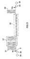
- Multiple applications of tensile strain can be attained by passing the aluminum material through a tensile strain application equipment one time (i.e. , one pass) using, for example, the tensile strain application equipment 2 shown in Fig. 2.
- This device 2 has three bridle roll units 20, 21, 22 which form two tension applying areas Q1 and Q2 between adjacent bridle roll units 20, 21 and 21 and 22.
- Disposing this device 2 in the transferring passage of the aluminum material S enables two applications of tensile strain by one pass.
- plural applications of tensile strain to the aluminum material can be carried out by one pass.
- a pass in which one pass enables plural applications of tensile strain can be performed a plurality of times.
- one bridle roll unit 21 is used to form two consecutive tension applying areas Q1 and Q2
- two tension applying areas can be formed discontinuously without forming two tensile applying areas by one bridle roll unit.
- a conventional tension leveling device can be used. That is, using a leveling device for leveling badness of shapes such as flatness by plastically deforming a part of a strip cross-section by tensile force not larger than the yield point and increased stress by bending, predetermined tensile strain can be given to a strip by adjusting the bridle roll peripheral speed conditions as mentioned above. Accordingly, by a tension leveling device, leveling of flatness and application of predetermined tensile strain can be performed.
- a method for supplying the aluminum material to the aforementioned tensile strain application equipment and carrying out the aluminum material after the application of tensile strain is not specifically limited.
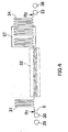
- a looper 31 is provided at the downstream side of an unwinding device 30.
- a coil connection is performed at the downstream side R1 of the unwinding device 30 while transferring aluminum material S at a certain rate so that the aluminum material is continuously supplied to the tensile strain application equipment 32 from a plurality of coils.
- a looper 34 Provided at the upstream side of a winding device 33 is a looper 34.
- the aluminum material S to which tensile strain is applied is cut at the upstream side R2 of the winding device 33 while transferring the aluminum material at a certain rate so that coiled aluminum material is continuously carried out.
- the reference numeral 35 denotes a standby coil to be loaded to the unwinding device 30
- the reference numeral 36 denotes a divided coil
- the reference numeral 37 denotes an annealing furnace.
- the aforementioned continuous processing can eliminate a time loss for exchanging coils at the unwinding device 30 and the winding device 33.
- the tensile strain application is not necessarily limited to be performed at one step or at one time. Accordingly, even if the tensile strain application is performed at several steps or performed several times, there will be no problem.
- an application of tensile strain is performed after intermediate annealing which is generally performed at 200 to 300 °C but before initiation of final annealing which is generally performed at 450 °C or above.
- steps of washing or slitting the aluminum material can be performed.
- at least one of an intermediate annealing step, a washing step, a slitting step and a final annealing step and a step of applying tensile strain can be performed continuously in one device or can be performed simultaneously.
- the intermediate annealing is generally performed at 200 to 300 °C, and can be performed quickly as the temperature raises.
- the important things are properties of the aluminum material after the intermediate annealing. If the intermediate annealing is performed at a high temperature or for a long time period to excessively recrystallize the aluminum material, or excessively soften the aluminum material, it becomes difficult to preferentially grow cube-oriented grains at the final annealing, resulting in deteriorated area fraction of cube orientation.
- the 0.2% proof stress in the rolling direction of the aluminum material after the intermediate annealing is preferably 25 to 100 MPa, more preferably 35 to 90 MPa.
- a method for performing the aforementioned intermediate annealing is not specifically limited.
- coiled aluminum material can be subjected to batch annealing, or when aluminum material is being rolled up on a winding coil while unwinding the aluminum material from an unwinding coil, the transferring aluminum material can be continuously annealed at between the unwinding coil and the winding coil.
- the intermediate annealing and the application of tensile strain can be performed continuously.
- the aluminum material S to be transferred from the unwinding device 30 is supplied to the annealing furnace 37 to perform the intermediate annealing therein and subsequently supplied to the tensile strain application equipment 32 to apply tensile strain to the aluminum material S.
- the application of tensile strain and the final annealing can be performed continuously.
- the annealing furnace 37 is disposed at the downstream side of the tensile strain application equipment 32, the aluminum material S to be transferred from the unwinding device 30 is supplied to the tensile strain application equipment 32 to apply tensile strain to the aluminum material S and subsequently supplied to the annealing furnace 37 to perform the final annealing therein.
- annealing furnaces are disposed at the upstream and downstream sides of the tensile strain application equipment 32, intermediate annealing, tensile strain application and final annealing can be performed continuously.
- compressive deformation of 5% or less in reduction can be given to the aluminum material.
- the compressive deformation can be performed by, for example, pinching the aluminum material which is being transferred from the unwinding coil to the winding coil with a pair of pinch rollers. This compressive deformation can be performed without using lubricant agent.
- Deposits such as contaminants may exist on the surface of the aluminum material. Therefore, to obtain excellent etching characteristics, these deposits should be deleted by washing before subjecting the aluminum material to the final annealing. In this case too, since almost no lubricant will be brought from the aluminum material, the washing steps can be simplified, e.g., washing time can be shortened, and contamination and deterioration of the washing liquid can be prevented. Furthermore, since the step of applying tensile strain can be performed by itself or can be performed simultaneously with another step, the elimination of such deposits on the surface of the aluminum material and the application of tensile strain can be performed simultaneously.
- manufacturing conditions other than the tensile strain application conditions are not specifically limited.
- the hot rolling, the cold rolling and the final annealing can be performed under well known conditions.
- the elimination of contaminants or oil content on the surface of the aluminum material or the washing of them can be performed arbitrarily.
- the intermediate annealing as previously explained, since the 0.2% proof stress of the aluminum material after the intermediate annealing is preferably 25 to 100 MPa, more preferably 30 to 90 MPa, conditions to obtain this are to be adjusted.
- scalping for eliminating the ingot surface can be performed before subjecting an aluminum ingot to hot rolling.
- homogenization treatment can be performed in accordance with common procedures.
- a method in which a tensile strain application equipment having bridle roll units is used to apply tensile strain is exemplified.
- the aforementioned explanations regarding the number of applying tensile strain, the number of passes, the continuous processing of the tensile strain application and the intermediate annealing, the continuous processing of the tensile strain application and the final annealing, the method of supplying the aluminum material to the tensile strain application step and the method of carrying out the aluminum material after the application of the tensile strain are not limited the case in which the tensile strain application equipment is used, and also can be applied to the case in which another tensile strain application equipment is used.
- the chemical compositions of the aluminum ingot are not limited, and can be any compositions capable of being used for electrolytic capacitor electrodes.
- the aluminum purity is preferably 99.8 mass% or more, more preferably 99.9 mass% or more.
- aluminum material to which various minor elements are added can also preferably be used.
- the thickness of the aluminum material to be manufactured by the method of the present invention is not limited.
- Aluminum material having a thickness of 200 ⁇ m or less, which is called a "foil," or a thickness exceeding 200 ⁇ m can be used in the present invention.
- the thickness of the aluminum material after the final annealing be 110 to 230 ⁇ m because of the following reasons. That is, if the thickness is 110 ⁇ m or more, grains easily coarsen at the final annealing, which further enhances the application significance of the present invention. Conversely, if the thickness is less than 110 ⁇ m, the coarsening of grains will not become a problem even if the present invention is not applied.
- the thickness of the aluminum material exceeds 230 ⁇ m, it becomes difficult to restrain the coarsening of grains even if the present invention is applied, which may results in the coarsened grains having a circle-equivalent diameter exceeding, e.g., 2 mm.
- the preferable lower limit of the thickness of the aluminum material after the final annealing is 115 ⁇ m, more preferably 120 ⁇ m.
- the preferable upper limit thereof is 210 ⁇ m, more preferably 200 ⁇ m.
- the aluminum material manufactured in accordance with the present invention is subjected to etching to enlarge the surface increasing rate. Since the aluminum material is high in area fraction of cube orientation due to the application of tensile strain and the subsequent final annealing, the surface increasing rate can be improved by the etching.
- the aluminum material manufactured in accordance with the present invention can be used as negative electrode material and positive electrode material as well.
- the aluminum material can be preferably used as a positive electrode material since the aluminum material has a large effective area even if a voltage endurance film is formed by chemical forming after the etching.
- the aluminum material is preferably used as medium voltage or high voltage electrolytic capacitor electrode material. An electrolytic capacitor using the electrode material can have large capacitance.
- Example 2 the ingot was subjected to hot rolling and cold rolling, then intermediate annealing under the conditions shown in Table 2.
- the intermediate annealed material was cut into 100 mm x 300 mm test pieces.
- tensile strain was applied to the test piece in the longitudinal direction with one axis tension tester.
- Example 8 the test piece was subjected to compressive deformation of 1.1% reduction by passing through pinch rollers without using lubricant.
- Comparative Examples 1 and 2 no tensile strain was applied. Thereafter, each test piece was subjected to final annealing under the conditions shown in Table 2.
- composition C as shown in Table 3 was subjected to homogenization treatment under the conditions of 610 °C x 10 hours.
- the ingot was subjected to hot rolling and cold rolling, then intermediate annealing.
- the conditions of the intermediate annealing was adjusted so that 0.2% proof stress of the aluminum material in the rolling direction after the intermediate annealing became to show the value shown in Table 4.
- a test piece of 10 mm in width and 200 mm in length obtained by cutting the aluminum material after the intermediate annealing was used.
- the aluminum material after the intermediate annealing was cut into 100 mm x 300 mm test pieces with the longitudinal direction parallel to the rolling direction.
- tensile strain was applied to the test piece in the longitudinal direction thereof with one axis tension tester.
- Comparative Example 11 no tensile strain was applied.
- Comparative Examples 12 and 13 after the intermediate annealing, the test piece was subjected to cold rolling at the rolling reduction shown in Table 4 without applying tensile stain.
- each test piece was subjected to final annealing for holding 10 hours at 500 °C to obtain the aluminum material having a thickness shown in Table 4.
- Comparative Example 11 in which tensile strain application and cold rolling were not performed after the intermediate annealing, the area fraction of cube orientation was low. Furthermore, in Comparative Examples 12 and 13 according to a conventional method in which cold rolling is performed without applying tensile strain after the intermediate annealing, coarsened grains were confirmed. Furthermore, in Comparative Example 14 in which the thickness exceeds 230 ⁇ m, coarsened grains were confirmed though tensile strain was applied after the intermediate annealing.
- tensile strain was applied to coiled material after the intermediate annealing using a tensile strain application equipment 1 as shown in Fig. 1.
- This tensile strain application equipment 1 is a tension leveling device having two bridle roll units 10 and 11 disposed at the upstream side and the downstream side of the aluminum material S. Each unit 10 and 11 is constituted by four bridle rolls 12 and 13, respectively.
- each ingot having the composition D, E and F shown in Table 5 was subjected to homogenization treatment of 610 °C x 10 hours.
- the ingot was subjected to hot rolling and cold rolling, and then to intermediate annealing to thereby obtain coiled material with a width of 1030 mm.
- the conditions of the intermediate annealing was adjusted so that 0.2% proof stress of the aluminum material in the rolling direction after the intermediate annealing became to show the value shown in Table 6.
- a test piece of 10 mm in width and 200 mm in length obtained by cutting the aluminum material after the intermediate annealing was used.
- Tensile strain was applied to the coiled material S after the intermediate annealing by differentiating the peripheral speed Pi of the upstream side bridle roll unit 10 and the peripheral speed Po of the downstream side bridle roll unit 11 and further setting (Po-Pi)/Pi to the value shown in Table 6 using the tensile strain application equipment 1.
- (Po-Pi)/Pi was set by changing the rotational speed of the bridle rolls 12 and 13.
- Examples 35 and 36 the same was set by changing the roll diameters of the bridle rolls 12 and 13.
- Example 37 the same was set by changing both the rotational speed and the roll diameters.
- the transferring speed of the aluminum material S and the number of pass to apply the tensile strain were set as shown in Table 6 to thereby eventually apply the tensile strain (%) shown in Table 6.
- the aluminum material to which tensile strain was applied was wound into coils each having a width of 500 mm, and subjected to final annealing of 500 ° C x 10 hours in an argon atmosphere to thereby obtain the aluminum material having the thickness shown in Table 6.
- a test piece with a width of 500 mm and length of 200 mm was obtained from the aluminum material after the final annealing.
- the existence of coarsened grains was judged by whether or not grains having circle-equivalent diameter of over 2 mm with respect to the area of the grain exist when the surface of the aluminum was observed.
- the method according to the present invention it is possible to stably obtain aluminum material for electrolytic capacitor electrodes having high area fraction of cube orientation and capable of restraining coarsening of grains. Accordingly, by subjecting this aluminum material to etching, the surface increasing rate can be increased to thereby increase the capacitance, resulting in a small and high performance electrolytic capacitor electrode, which in turn can provide a small and high performance electronics device having the electrolytic capacitor.
Landscapes
- Engineering & Computer Science (AREA)
- Chemical & Material Sciences (AREA)
- Mechanical Engineering (AREA)
- Materials Engineering (AREA)
- Power Engineering (AREA)
- Physics & Mathematics (AREA)
- Microelectronics & Electronic Packaging (AREA)
- Thermal Sciences (AREA)
- Crystallography & Structural Chemistry (AREA)
- Metallurgy (AREA)
- Organic Chemistry (AREA)
- Metal Rolling (AREA)
- Fixed Capacitors And Capacitor Manufacturing Machines (AREA)
- Electrolytic Production Of Metals (AREA)
Abstract
Description
| Ingot No. | Chemical compositions | |||||||||
| (Unit: Al [mass%], another elements: [mass ppm]) | ||||||||||
| Si | Fe | Cu | Mn | Mg | Zn | Ti | B | Pb | Al | |
| A | 23 | 16 | 49 | 1 | 1 | 10 | 1 | 1 | 0.6 | 99.98 or more |
| B | 46 | 60 | 18 | 2 | 5 | 12 | 1 | 4 | 0.7 | 99.98 or more |

| Ingot No. | Chemical compositions | ||||||
| (Unit: Al [mass%], another elements: [mass ppm]) | |||||||
| Si | Fe | Cu | Zn | Ga | Pb | Al | |
| C | 23 | 15 | 51 | 11 | 8 | 0.61 | 99.98 or more |

| Ingot No. | Chemical compositions | ||||||
| (Unit: Al [mass%], another elements: [mass ppm]) | |||||||
| Si | Fe | Cu | Zn | Ga | Pb | Al | |
| D | 23 | 15 | 51 | 11 | 8 | 0.6 | 99.98 or |
| E | |||||||
| 20 | 13 | 58 | 10 | 9 | 0.6 | 99.98 or | |
| F | |||||||
| 10 | 9 | 36 | 9 | 1 | 1.0 | 99.99 or more |
| Example | |||||||
| 31 | 32 | 33 | 34 | 35 | 36 | 37 | |
| Ingot composition | D | D | D | D | E | E | F |
| 0.2% proof stress after Intermediate annealing | 39 | 39 | 39 | 41 | 62 | 31 | 57 |
| (Po-Pi)/Pi | 0.009 | 0.009 | 0.009 | 0.009 | 0.045 | 0.087 | 0.041 |
| Number of | 2 | 4 | 6 | 6 | 2 | 1 | 2 |
| Transferring speed (m/min) | 80 | 80 | 80 | 80 | 90 | 80 | 90 |
| Tensile strain (%) | 1.4 | 3.3 | 4.1 | 4.3 | 7.6 | 7.8 | 7.0 |
| Thickness (µm) | 144 | 141 | 140 | 111 | 113 | 113 | 121 |
| Area fraction of cube orientation (%) | 97.6 | 97.6 | 99.0 | 98.0 | 99.7 | 99.4 | 99.4 |
| Existence of coarsened grains | Nil | Nil | Nil | Nil | Nil | Nil | Nil |
Claims (19)
- A method for manufacturing aluminum material for electrolytic capacitor electrodes, wherein an aluminum ingot is subjected to hot rolling, cold rolling and then intermediate annealing to obtain a rolled article, and wherein tensile strain is applied to the rolled article without subjecting the rolled article to cold rolling after the intermediate annealing but before initiation of final annealing, and thereafter the rolled article is subjected final annealing.
- The method for manufacturing aluminum material for electrolytic capacitor electrodes as claimed in claim 1, wherein the tensile strain falls within the range of 1 to 15%.
- The method for manufacturing aluminum material for electrolytic capacitor electrodes as claimed in claim 2, wherein the tensile strain falls within the range of 3 to 12%.
- The method for manufacturing aluminum material for electrolytic capacitor electrodes as claimed in any one of claims 1 to 3, wherein application of the tensile strain is performed using a tensile strain application equipment having two or more bridle roll units disposed in a transferring direction of the aluminum material for forming a tension applying area between adjacent bridle roll units in such a manner that between a peripheral speed Pi of an upstream-side bridle roll unit and a peripheral speed Po of a downstream-side bridle roll a peripheral speed difference of Pi<Po is provided so as to continuously generate plastic strain in the tension applying area.
- The method for manufacturing aluminum material for electrolytic capacitor electrodes as claimed in claim 4, wherein the peripheral speeds P1 and Po meet a relation of 0<(Po-Pi)/Pi ≦0.1.
- The method for manufacturing aluminum material for electrolytic capacitor electrodes as claimed in claim 4 or 5, wherein the peripheral speed difference is generated by driving bridle rolls of the upstream-side bridle roll unit and those of the downstream-side bridle roll unit at different rotational speeds.
- The method for manufacturing aluminum material for electrolytic capacitor electrodes as claimed in any one of claims 4 to 6, wherein the peripheral speed difference is generated by employing bridle rolls of the downstream-side bridle roll unit with a larger bridle roll diameter than a bridle roll diameter of bridle rolls of the upstream-side bridle roll unit.
- The method for manufacturing aluminum material for electrolytic capacitor electrodes as claimed in any one of claims 1 to 7, wherein the tensile stain is applied at two positions or more in one pass for applying the tensile strain.
- The method for manufacturing aluminum material for electrolytic capacitor electrodes as claimed in any one of claims 1 to 8, wherein the pass for applying the tensile strain is carried out a plurality of times.
- The method for manufacturing aluminum material for electrolytic capacitor electrodes as claimed in any one of claims 4 to 9, wherein the tensile strain application equipment is a tension leveling device.
- The method for manufacturing aluminum material for electrolytic capacitor electrodes as claimed in any one of claims 1 to 10, wherein the intermediate annealing and an application of the tensile strain are performed continuously.
- The method for manufacturing aluminum material for electrolytic capacitor electrodes as claimed in any one of claims 1 to 11, wherein an application of the tensile strain and the final annealing are performed continuously.
- The method for manufacturing aluminum material for electrolytic capacitor electrodes as claimed in any one of claims 1 to 12, wherein the method manufactures the aluminum material having a thickness of 110 to 230 µm.
- The method for manufacturing aluminum material for electrolytic capacitor electrodes as claimed in any one of claims 1 to 13, wherein the aluminum material after the intermediate annealing is 25 to 100 MPa in 0.2% proof stress in the rolling direction.
- The method for manufacturing aluminum material for electrolytic capacitor electrodes as claimed in any one of claims 1 to 14, wherein no coarsened grain with a circle-equivalent diameter of over 2 mm exists on the surface of the aluminum material after the final annealing.
- The method for manufacturing aluminum material for electrolytic capacitor electrodes as claimed in any one of claims 1 to 15, wherein the aluminum material is positive electrode material.
- The method for manufacturing aluminum material for electrolytic capacitor electrodes as claimed in any one of claims 1 to 16, wherein the aluminum material is medium and high voltage positive electrode material.
- Aluminum material for electrolytic capacitor electrodes manufactured by the method as recited in any one of claims 1 to 17.
- An electrolytic capacitor, wherein the aluminum material for electrolytic electrodes as recited in claim 18 is used as electrode material.
Applications Claiming Priority (11)
| Application Number | Priority Date | Filing Date | Title |
|---|---|---|---|
| JP2002188860 | 2002-06-28 | ||
| JP2002188860 | 2002-06-28 | ||
| JP2002338765 | 2002-11-22 | ||
| JP2002338765 | 2002-11-22 | ||
| JP2002361131 | 2002-12-12 | ||
| JP2002361131 | 2002-12-12 | ||
| US46233303P | 2003-04-14 | 2003-04-14 | |
| US462333P | 2003-04-14 | ||
| JP2003144058 | 2003-05-21 | ||
| JP2003144058 | 2003-05-21 | ||
| PCT/JP2003/008113 WO2004003248A1 (en) | 2002-06-28 | 2003-06-25 | Process for producing aluminum material for electrolytic capacitor electrode, aluminum material for electrolytic capacitor electrode and electrolytic capacitor |
Publications (4)
| Publication Number | Publication Date |
|---|---|
| EP1541704A1 true EP1541704A1 (en) | 2005-06-15 |
| EP1541704A4 EP1541704A4 (en) | 2006-05-24 |
| EP1541704B1 EP1541704B1 (en) | 2009-08-26 |
| EP1541704B9 EP1541704B9 (en) | 2009-12-23 |
Family
ID=30004024
Family Applications (1)
| Application Number | Title | Priority Date | Filing Date |
|---|---|---|---|
| EP03741124A Expired - Lifetime EP1541704B9 (en) | 2002-06-28 | 2003-06-25 | Process for producing aluminum material for electrolytic capacitor electrode |
Country Status (7)
| Country | Link |
|---|---|
| EP (1) | EP1541704B9 (en) |
| JP (1) | JP4332117B2 (en) |
| CN (1) | CN1294291C (en) |
| AT (1) | ATE440975T1 (en) |
| AU (1) | AU2003280408A1 (en) |
| DE (1) | DE60329004D1 (en) |
| WO (1) | WO2004003248A1 (en) |
Families Citing this family (12)
| Publication number | Priority date | Publication date | Assignee | Title |
|---|---|---|---|---|
| JP4763273B2 (en) * | 2003-12-10 | 2011-08-31 | 昭和電工株式会社 | Method for manufacturing electrode material for electrolytic capacitor |
| WO2005078751A1 (en) * | 2004-02-17 | 2005-08-25 | Showa Denko K.K. | Method of manufacturing aluminum material for electrolytic capacitor electrodes, aluminum material for electrolytic capacitor electrodes, anode material for aluminum electrolytic capacitors, and aluminum electrolytic capacitors |
| JP4690182B2 (en) * | 2004-12-01 | 2011-06-01 | 昭和電工株式会社 | Method for producing aluminum material for electrolytic capacitor electrode, aluminum material for electrolytic capacitor electrode, anode material for aluminum electrolytic capacitor, and aluminum electrolytic capacitor |
| JP4732892B2 (en) * | 2004-12-27 | 2011-07-27 | 昭和電工株式会社 | Method for producing aluminum material for electrolytic capacitor electrode, aluminum material for electrolytic capacitor electrode, anode material for aluminum electrolytic capacitor, and aluminum electrolytic capacitor |
| JP4874589B2 (en) * | 2005-07-07 | 2012-02-15 | 昭和電工株式会社 | Method for manufacturing aluminum material for electrolytic capacitor electrode, aluminum material for electrolytic capacitor electrode, method for manufacturing electrode material for electrolytic capacitor, anode material for aluminum electrolytic capacitor, and aluminum electrolytic capacitor |
| JP4874596B2 (en) * | 2005-08-02 | 2012-02-15 | 昭和電工株式会社 | Method for manufacturing aluminum material for electrolytic capacitor electrode, aluminum material for electrolytic capacitor electrode, method for manufacturing electrode material for electrolytic capacitor, anode material for aluminum electrolytic capacitor, and aluminum electrolytic capacitor |
| JP4874600B2 (en) * | 2005-08-12 | 2012-02-15 | 昭和電工株式会社 | Method for manufacturing aluminum material for electrolytic capacitor electrode, aluminum material for electrolytic capacitor electrode, method for manufacturing electrode material for electrolytic capacitor, anode material for aluminum electrolytic capacitor, and aluminum electrolytic capacitor |
| CN102259481B (en) * | 2011-06-02 | 2013-07-03 | 广东东南薄膜科技股份有限公司 | Method for determining length of film by thermally stretching film |
| CN102581041A (en) * | 2012-03-05 | 2012-07-18 | 无锡亚新通用机械有限公司 | Strip tensioning device |
| WO2017018029A1 (en) * | 2015-07-30 | 2017-02-02 | 昭和電工株式会社 | Method for producing aluminum material for electrolytic capacitor electrodes, method for producing electrode material for aluminum electrolytic capacitor, and method for producing aluminum electrolytic capacitor |
| JP6752110B2 (en) * | 2016-10-28 | 2020-09-09 | 三菱アルミニウム株式会社 | Manufacturing method of aluminum foil for electrolytic capacitors, aluminum foil for electrolytic capacitors, and electrodes for electrolytic capacitors |
| CN110923593B (en) * | 2019-11-27 | 2021-03-30 | 新疆众和股份有限公司 | Intermediate annealing process of high-voltage anode aluminum foil for electrolytic capacitor |
Family Cites Families (8)
| Publication number | Priority date | Publication date | Assignee | Title |
|---|---|---|---|---|
| FR2113782B1 (en) * | 1970-11-16 | 1973-06-08 | Pechiney | |
| EP0142460B1 (en) * | 1983-08-25 | 1987-09-16 | Schweizerische Aluminium Ag | Process for producing thin aluminium strips and foils with a predominant dice structure |
| JPH06145923A (en) * | 1992-10-30 | 1994-05-27 | Nippon Foil Mfg Co Ltd | Manufacture of aluminum foil for electrolytic condenser anode |
| JPH08319547A (en) * | 1995-05-23 | 1996-12-03 | Kobe Steel Ltd | Production of aluminum foil for electrolytic capacitor |
| JPH108225A (en) * | 1996-06-19 | 1998-01-13 | Showa Alum Corp | Manufacturing method of aluminum foil for electrode of electrolytic capacitor |
| JPH1143749A (en) * | 1997-07-22 | 1999-02-16 | Showa Alum Corp | Method for producing aluminum foil for lithium battery with low distortion |
| JP4916605B2 (en) * | 1999-11-26 | 2012-04-18 | 昭和電工株式会社 | Aluminum material for electrolytic capacitor electrode, aluminum foil, and method for producing aluminum foil |
| IT1316715B1 (en) * | 2000-03-03 | 2003-04-24 | A M T Robotics S R L | PROCEDURE FOR THE REALIZATION OF METAL TUBES AND RELATED EQUIPMENT |
-
2003
- 2003-06-25 AU AU2003280408A patent/AU2003280408A1/en not_active Abandoned
- 2003-06-25 AT AT03741124T patent/ATE440975T1/en not_active IP Right Cessation
- 2003-06-25 DE DE60329004T patent/DE60329004D1/en not_active Expired - Lifetime
- 2003-06-25 JP JP2004548903A patent/JP4332117B2/en not_active Expired - Lifetime
- 2003-06-25 WO PCT/JP2003/008113 patent/WO2004003248A1/en not_active Ceased
- 2003-06-25 EP EP03741124A patent/EP1541704B9/en not_active Expired - Lifetime
- 2003-06-25 CN CNB038153343A patent/CN1294291C/en not_active Expired - Fee Related
Also Published As
| Publication number | Publication date |
|---|---|
| AU2003280408A1 (en) | 2004-01-19 |
| CN1665953A (en) | 2005-09-07 |
| EP1541704B1 (en) | 2009-08-26 |
| WO2004003248A1 (en) | 2004-01-08 |
| ATE440975T1 (en) | 2009-09-15 |
| DE60329004D1 (en) | 2009-10-08 |
| JP4332117B2 (en) | 2009-09-16 |
| EP1541704B9 (en) | 2009-12-23 |
| EP1541704A4 (en) | 2006-05-24 |
| JPWO2004003248A1 (en) | 2005-10-27 |
| CN1294291C (en) | 2007-01-10 |
Similar Documents
| Publication | Publication Date | Title |
|---|---|---|
| EP3330393B1 (en) | Magnesium alloy sheet | |
| EP1541704B9 (en) | Process for producing aluminum material for electrolytic capacitor electrode | |
| EP3290539B1 (en) | Non-oriented magnetic steel sheet | |
| EP3778941A1 (en) | Copper alloy for electronic/electric device, copper alloy sheet/strip material for electronic/electric device, component for electronic/electric device, terminal, and busbar | |
| EP2453031B1 (en) | Magnesium alloy plate | |
| CN106103756B (en) | The manufacturing method of copper alloy plate, connector and copper alloy plate | |
| KR20200101339A (en) | Battery electrode foil for manufacturing high-strength lithium-ion storage batteries | |
| CN113727788B (en) | Method for producing non-oriented electromagnetic steel sheet | |
| EP2239347A1 (en) | Aluminum alloy sheet for motor vehicle and process for producing the same | |
| EP1771590B1 (en) | Method for manufacturing an aluminum alloy sheet | |
| WO2017168890A1 (en) | Al-mg-si-based alloy material, al-mg-si-based alloy plate, and method for manufacturing al-mg-si-based alloy plate | |
| JP2020059050A (en) | Rolling equipment and rolling method of steel plate | |
| JP3500072B2 (en) | Titanium material for drum for producing electrolytic metal foil and method for producing the same | |
| CN113825850A (en) | Magnesium alloy sheet material, press-formed body, and method for producing magnesium alloy sheet material | |
| JPH11189836A (en) | Al-mg-si aluminum alloy sheet to be formed excellent in surface properties | |
| JP2001303223A (en) | Method for producing titanium plate excellent in formability | |
| JP4763273B2 (en) | Method for manufacturing electrode material for electrolytic capacitor | |
| JP2000045067A (en) | High purity titanium plate for titanium target material and method for producing the same | |
| KR100978458B1 (en) | Manufacturing method of aluminum material for electrolytic capacitor electrode and aluminum material and electrolytic capacitor for electrolytic capacitor electrode | |
| JP7525077B2 (en) | Manufacturing method of non-oriented electrical steel sheet and cold rolled sheet | |
| CN115210010A (en) | Method for manufacturing processed titanium material | |
| JP3951564B2 (en) | Hot rolled titanium plate for surface member of electrolytic deposition drum and method for producing the same | |
| JP4372675B2 (en) | Method for producing aluminum material for electrolytic capacitor electrode | |
| JP2578040B2 (en) | Manufacturing method of ultra-high silicon electrical steel sheet | |
| JP2005186112A (en) | Method for producing non-oriented electrical steel sheet |
Legal Events
| Date | Code | Title | Description |
|---|---|---|---|
| PUAI | Public reference made under article 153(3) epc to a published international application that has entered the european phase |
Free format text: ORIGINAL CODE: 0009012 |
|
| 17P | Request for examination filed |
Effective date: 20050128 |
|
| AK | Designated contracting states |
Kind code of ref document: A1 Designated state(s): AT BE BG CH CY CZ DE DK EE ES FI FR GB GR HU IE IT LI LU MC NL PT RO SE SI SK TR |
|
| AX | Request for extension of the european patent |
Extension state: AL LT LV MK |
|
| DAX | Request for extension of the european patent (deleted) | ||
| A4 | Supplementary search report drawn up and despatched |
Effective date: 20060412 |
|
| 17Q | First examination report despatched |
Effective date: 20070129 |
|
| GRAP | Despatch of communication of intention to grant a patent |
Free format text: ORIGINAL CODE: EPIDOSNIGR1 |
|
| RTI1 | Title (correction) |
Free format text: PROCESS FOR PRODUCING ALUMINUM MATERIAL FOR ELECTROLYTIC CAPACITOR ELECTRODE |
|
| RIN1 | Information on inventor provided before grant (corrected) |
Inventor name: AKAGI, NOBUHIKOC/O SAKAI REGIONAL OFFICE Inventor name: SAKAGUCHI, MASASHIC/O SAKAI REGIONAL OFFICE Inventor name: HODZUMI, SATOSHIC/O SAKAI REGIONAL OFFICE |
|
| GRAS | Grant fee paid |
Free format text: ORIGINAL CODE: EPIDOSNIGR3 |
|
| GRAA | (expected) grant |
Free format text: ORIGINAL CODE: 0009210 |
|
| AK | Designated contracting states |
Kind code of ref document: B1 Designated state(s): AT BE BG CH CY CZ DE DK EE ES FI FR GB GR HU IE IT LI LU MC NL PT RO SE SI SK TR |
|
| REG | Reference to a national code |
Ref country code: GB Ref legal event code: FG4D |
|
| REG | Reference to a national code |
Ref country code: CH Ref legal event code: EP |
|
| REG | Reference to a national code |
Ref country code: IE Ref legal event code: FG4D |
|
| REF | Corresponds to: |
Ref document number: 60329004 Country of ref document: DE Date of ref document: 20091008 Kind code of ref document: P |
|
| RIN2 | Information on inventor provided after grant (corrected) |
Inventor name: HODZUMI, SATOSHIC/O SAKAI REGIONAL OFFICE Inventor name: SAKAGUCHI, MASASHIC/O SAKAI REGIONAL OFFICE Inventor name: AKAGI, NOBUHIKOC/O SAKAI REGIONAL OFFICE |
|
| PG25 | Lapsed in a contracting state [announced via postgrant information from national office to epo] |
Ref country code: SE Free format text: LAPSE BECAUSE OF FAILURE TO SUBMIT A TRANSLATION OF THE DESCRIPTION OR TO PAY THE FEE WITHIN THE PRESCRIBED TIME-LIMIT Effective date: 20090826 Ref country code: AT Free format text: LAPSE BECAUSE OF FAILURE TO SUBMIT A TRANSLATION OF THE DESCRIPTION OR TO PAY THE FEE WITHIN THE PRESCRIBED TIME-LIMIT Effective date: 20090826 Ref country code: FI Free format text: LAPSE BECAUSE OF FAILURE TO SUBMIT A TRANSLATION OF THE DESCRIPTION OR TO PAY THE FEE WITHIN THE PRESCRIBED TIME-LIMIT Effective date: 20090826 |
|
| NLV1 | Nl: lapsed or annulled due to failure to fulfill the requirements of art. 29p and 29m of the patents act | ||
| PG25 | Lapsed in a contracting state [announced via postgrant information from national office to epo] |
Ref country code: NL Free format text: LAPSE BECAUSE OF FAILURE TO SUBMIT A TRANSLATION OF THE DESCRIPTION OR TO PAY THE FEE WITHIN THE PRESCRIBED TIME-LIMIT Effective date: 20090826 Ref country code: SI Free format text: LAPSE BECAUSE OF FAILURE TO SUBMIT A TRANSLATION OF THE DESCRIPTION OR TO PAY THE FEE WITHIN THE PRESCRIBED TIME-LIMIT Effective date: 20090826 |
|
| PG25 | Lapsed in a contracting state [announced via postgrant information from national office to epo] |
Ref country code: CY Free format text: LAPSE BECAUSE OF FAILURE TO SUBMIT A TRANSLATION OF THE DESCRIPTION OR TO PAY THE FEE WITHIN THE PRESCRIBED TIME-LIMIT Effective date: 20090826 Ref country code: PT Free format text: LAPSE BECAUSE OF FAILURE TO SUBMIT A TRANSLATION OF THE DESCRIPTION OR TO PAY THE FEE WITHIN THE PRESCRIBED TIME-LIMIT Effective date: 20091228 Ref country code: BG Free format text: LAPSE BECAUSE OF FAILURE TO SUBMIT A TRANSLATION OF THE DESCRIPTION OR TO PAY THE FEE WITHIN THE PRESCRIBED TIME-LIMIT Effective date: 20091126 |
|
| PG25 | Lapsed in a contracting state [announced via postgrant information from national office to epo] |
Ref country code: DK Free format text: LAPSE BECAUSE OF FAILURE TO SUBMIT A TRANSLATION OF THE DESCRIPTION OR TO PAY THE FEE WITHIN THE PRESCRIBED TIME-LIMIT Effective date: 20090826 Ref country code: ES Free format text: LAPSE BECAUSE OF FAILURE TO SUBMIT A TRANSLATION OF THE DESCRIPTION OR TO PAY THE FEE WITHIN THE PRESCRIBED TIME-LIMIT Effective date: 20091207 Ref country code: RO Free format text: LAPSE BECAUSE OF FAILURE TO SUBMIT A TRANSLATION OF THE DESCRIPTION OR TO PAY THE FEE WITHIN THE PRESCRIBED TIME-LIMIT Effective date: 20090826 Ref country code: CZ Free format text: LAPSE BECAUSE OF FAILURE TO SUBMIT A TRANSLATION OF THE DESCRIPTION OR TO PAY THE FEE WITHIN THE PRESCRIBED TIME-LIMIT Effective date: 20090826 Ref country code: EE Free format text: LAPSE BECAUSE OF FAILURE TO SUBMIT A TRANSLATION OF THE DESCRIPTION OR TO PAY THE FEE WITHIN THE PRESCRIBED TIME-LIMIT Effective date: 20090826 |
|
| PG25 | Lapsed in a contracting state [announced via postgrant information from national office to epo] |
Ref country code: SK Free format text: LAPSE BECAUSE OF FAILURE TO SUBMIT A TRANSLATION OF THE DESCRIPTION OR TO PAY THE FEE WITHIN THE PRESCRIBED TIME-LIMIT Effective date: 20090826 |
|
| PG25 | Lapsed in a contracting state [announced via postgrant information from national office to epo] |
Ref country code: BE Free format text: LAPSE BECAUSE OF FAILURE TO SUBMIT A TRANSLATION OF THE DESCRIPTION OR TO PAY THE FEE WITHIN THE PRESCRIBED TIME-LIMIT Effective date: 20090826 |
|
| PLBE | No opposition filed within time limit |
Free format text: ORIGINAL CODE: 0009261 |
|
| 26N | No opposition filed |
Effective date: 20100527 |
|
| PG25 | Lapsed in a contracting state [announced via postgrant information from national office to epo] |
Ref country code: GR Free format text: LAPSE BECAUSE OF FAILURE TO SUBMIT A TRANSLATION OF THE DESCRIPTION OR TO PAY THE FEE WITHIN THE PRESCRIBED TIME-LIMIT Effective date: 20091127 |
|
| PG25 | Lapsed in a contracting state [announced via postgrant information from national office to epo] |
Ref country code: MC Free format text: LAPSE BECAUSE OF NON-PAYMENT OF DUE FEES Effective date: 20100630 |
|
| REG | Reference to a national code |
Ref country code: CH Ref legal event code: PL |
|
| GBPC | Gb: european patent ceased through non-payment of renewal fee |
Effective date: 20100625 |
|
| PG25 | Lapsed in a contracting state [announced via postgrant information from national office to epo] |
Ref country code: LI Free format text: LAPSE BECAUSE OF NON-PAYMENT OF DUE FEES Effective date: 20100630 Ref country code: CH Free format text: LAPSE BECAUSE OF NON-PAYMENT OF DUE FEES Effective date: 20100630 Ref country code: IE Free format text: LAPSE BECAUSE OF NON-PAYMENT OF DUE FEES Effective date: 20100625 |
|
| PG25 | Lapsed in a contracting state [announced via postgrant information from national office to epo] |
Ref country code: GB Free format text: LAPSE BECAUSE OF NON-PAYMENT OF DUE FEES Effective date: 20100625 |
|
| PG25 | Lapsed in a contracting state [announced via postgrant information from national office to epo] |
Ref country code: LU Free format text: LAPSE BECAUSE OF NON-PAYMENT OF DUE FEES Effective date: 20100625 Ref country code: HU Free format text: LAPSE BECAUSE OF FAILURE TO SUBMIT A TRANSLATION OF THE DESCRIPTION OR TO PAY THE FEE WITHIN THE PRESCRIBED TIME-LIMIT Effective date: 20100227 |
|
| PG25 | Lapsed in a contracting state [announced via postgrant information from national office to epo] |
Ref country code: TR Free format text: LAPSE BECAUSE OF FAILURE TO SUBMIT A TRANSLATION OF THE DESCRIPTION OR TO PAY THE FEE WITHIN THE PRESCRIBED TIME-LIMIT Effective date: 20090826 |
|
| REG | Reference to a national code |
Ref country code: FR Ref legal event code: PLFP Year of fee payment: 14 |
|
| REG | Reference to a national code |
Ref country code: FR Ref legal event code: PLFP Year of fee payment: 15 |
|
| REG | Reference to a national code |
Ref country code: FR Ref legal event code: PLFP Year of fee payment: 16 |
|
| PGFP | Annual fee paid to national office [announced via postgrant information from national office to epo] |
Ref country code: FR Payment date: 20210513 Year of fee payment: 19 Ref country code: DE Payment date: 20210602 Year of fee payment: 19 Ref country code: IT Payment date: 20210511 Year of fee payment: 19 |
|
| REG | Reference to a national code |
Ref country code: DE Ref legal event code: R119 Ref document number: 60329004 Country of ref document: DE |
|
| PG25 | Lapsed in a contracting state [announced via postgrant information from national office to epo] |
Ref country code: FR Free format text: LAPSE BECAUSE OF NON-PAYMENT OF DUE FEES Effective date: 20220630 |
|
| PG25 | Lapsed in a contracting state [announced via postgrant information from national office to epo] |
Ref country code: DE Free format text: LAPSE BECAUSE OF NON-PAYMENT OF DUE FEES Effective date: 20230103 |
|
| PG25 | Lapsed in a contracting state [announced via postgrant information from national office to epo] |
Ref country code: IT Free format text: LAPSE BECAUSE OF NON-PAYMENT OF DUE FEES Effective date: 20220625 |