EP1541445A1 - Control device for motorized power steering device - Google Patents
Control device for motorized power steering device Download PDFInfo
- Publication number
- EP1541445A1 EP1541445A1 EP03797578A EP03797578A EP1541445A1 EP 1541445 A1 EP1541445 A1 EP 1541445A1 EP 03797578 A EP03797578 A EP 03797578A EP 03797578 A EP03797578 A EP 03797578A EP 1541445 A1 EP1541445 A1 EP 1541445A1
- Authority
- EP
- European Patent Office
- Prior art keywords
- steering
- sat
- torque
- electric power
- motor
- Prior art date
- Legal status (The legal status is an assumption and is not a legal conclusion. Google has not performed a legal analysis and makes no representation as to the accuracy of the status listed.)
- Granted
Links
Images



Classifications
-
- B—PERFORMING OPERATIONS; TRANSPORTING
- B62—LAND VEHICLES FOR TRAVELLING OTHERWISE THAN ON RAILS
- B62D—MOTOR VEHICLES; TRAILERS
- B62D5/00—Power-assisted or power-driven steering
- B62D5/04—Power-assisted or power-driven steering electrical, e.g. using an electric servo-motor connected to, or forming part of, the steering gear
- B62D5/0442—Conversion of rotational into longitudinal movement
- B62D5/0445—Screw drives
- B62D5/0448—Ball nuts
-
- B—PERFORMING OPERATIONS; TRANSPORTING
- B62—LAND VEHICLES FOR TRAVELLING OTHERWISE THAN ON RAILS
- B62D—MOTOR VEHICLES; TRAILERS
- B62D5/00—Power-assisted or power-driven steering
- B62D5/04—Power-assisted or power-driven steering electrical, e.g. using an electric servo-motor connected to, or forming part of, the steering gear
- B62D5/0457—Power-assisted or power-driven steering electrical, e.g. using an electric servo-motor connected to, or forming part of, the steering gear characterised by control features of the drive means as such
- B62D5/046—Controlling the motor
- B62D5/0463—Controlling the motor calculating assisting torque from the motor based on driver input
-
- B—PERFORMING OPERATIONS; TRANSPORTING
- B62—LAND VEHICLES FOR TRAVELLING OTHERWISE THAN ON RAILS
- B62D—MOTOR VEHICLES; TRAILERS
- B62D5/00—Power-assisted or power-driven steering
- B62D5/04—Power-assisted or power-driven steering electrical, e.g. using an electric servo-motor connected to, or forming part of, the steering gear
- B62D5/0457—Power-assisted or power-driven steering electrical, e.g. using an electric servo-motor connected to, or forming part of, the steering gear characterised by control features of the drive means as such
- B62D5/046—Controlling the motor
- B62D5/0466—Controlling the motor for returning the steering wheel to neutral position
-
- B—PERFORMING OPERATIONS; TRANSPORTING
- B62—LAND VEHICLES FOR TRAVELLING OTHERWISE THAN ON RAILS
- B62D—MOTOR VEHICLES; TRAILERS
- B62D5/00—Power-assisted or power-driven steering
- B62D5/04—Power-assisted or power-driven steering electrical, e.g. using an electric servo-motor connected to, or forming part of, the steering gear
- B62D5/0457—Power-assisted or power-driven steering electrical, e.g. using an electric servo-motor connected to, or forming part of, the steering gear characterised by control features of the drive means as such
- B62D5/046—Controlling the motor
- B62D5/0472—Controlling the motor for damping vibrations
-
- B—PERFORMING OPERATIONS; TRANSPORTING
- B62—LAND VEHICLES FOR TRAVELLING OTHERWISE THAN ON RAILS
- B62D—MOTOR VEHICLES; TRAILERS
- B62D6/00—Arrangements for automatically controlling steering depending on driving conditions sensed and responded to, e.g. control circuits
- B62D6/008—Control of feed-back to the steering input member, e.g. simulating road feel in steer-by-wire applications
Definitions
- the present invention relates to an electric power steering apparatus in which a steering assist force caused by a motor is given to a steering system of a car or a vehicle, and more particularly, to an electric power steering apparatus comprising a control system with two degree of freedom which is capable of independently designing steering feeling and road information sensitivity to realize ideal steering feeling and road information sensitivity at the same time in a frequency region.
- the electric power steering apparatus for assist-load energizing the steering apparatus of a car or a vehicle with rotation force of a motor is designed to assist-load energize a steering shaft or a rack shaft with a driving force of the motor by a transmission mechanism such as a gear or a belt through a speed reducer.
- a transmission mechanism such as a gear or a belt through a speed reducer.
- the feedback control is for adjusting voltage to be applied to the motor such as to reduce a difference between a current command value and a motor current detection value, and the voltage to be applied to the motor is generally conducted by adjusting a duty ratio of a PWM (pulse width modulation) control.
- PWM pulse width modulation
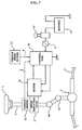
- a column shaft 2 of a steering wheel 1 is connected to a tie rod 6 of a running wheel through a speed reducing gear 3, universal joints 4a and 4b and a pinion rack mechanism 5.
- the column shaft 2 is provided with a torque sensor 10 for detecting the steering torque of the steering wheel 1.
- a motor 20 for assisting the steering torque of the steering wheel 1 is connected to the column shaft 2 through the speed reducing gear 3. Electricity is supplied to a control unit 30 which controls the power steering apparatus from the battery 14 through an ignition key 11 and a relay 13.
- the control unit 30 calculates a steering assist command value I of assist command based on the steering torque T detected by the torque sensor 10 and based on vehicle speed V detected by the vehicle speed sensor 12, and the control unit 30 controls current to be supplied to the motor 20 based on the calculated steering assist command value I.
- the control unit 30 mainly comprises a CPU (including MPU also), and general functions of the control unit 30 executed by program in the CPU are shown in Fig. 8.
- a phase compensator 31 is not a phase compensator as independent hardware, but is a phase compensating function executed by the CPU.
- the steering torque T which is detected and inputted by the torque sensor 10 is compensated in phase by the phase compensator 31 for enhancing the safety of the steering system.
- the steering torque TA which was compensated in phase is input to a steering assist command value calculating element 32.
- the vehicle speed V detected by the vehicle speed sensor 12 is also input to the steering assist command value calculating element 32.
- the steering assist command value calculating element 32 determines the steering assist command value I which is a control target value of current to be supplied to the motor 20 based on the input steering torque TA and vehicle speed V.
- the steering assist command value I is input to a subtracter 30A and is also input to a differentiation compensator 34 of a feedforward system for enhancing the response speed.
- a deviation (I-i) of the subtracter 30A is input to a proportion calculating element 35 and is also input to an integration calculating element 36 for improving the characteristics of the feedback system.
- the output of the differentiation compensator 34 and outputs of the proportion calculating element 35 and the integration calculating element 36 are added and input to an adder 30B.
- a current control value E which is a result of addition in the adder 30B is input to a motor drive circuit 37 as a motor driving signal.
- the current i of the motor 20 is detected by a motor current detection circuit 38 and is fed back to the subtracter 30A.
- the complementary sensitivity function with respect to frequency of the control apparatus is set a value approaching "1" in a band where there exists disturbance to be suppressed, and is set to a value approaching zero in a band where there exists disturbance to be transmitted.
- the complementary sensitivity function when the function is "1", this means that the disturbance is suppressed, and when the function is zero, this means that the disturbance is not suppressed at all and is transmitted.
- the steering feeling and the road information sensitivity can be used as indices of performance evaluation in the electric power steering apparatus.
- the conventional electric power steering apparatus has a problem that since the transmitting characteristics representing these two indices have mutual subordinative relation, it is difficult to design a control system which satisfies the two indices at the same time. That is, since the steering feeling and the road information sensitivity have the mutual subordinative relation, the steering feeling and the road information sensitivity can not be designed independently, and it is difficult to design a control apparatus which satisfies the ideal steering feeling and road information sensitivity at the same time.
- the present invention has been accomplished in view of the above circumferences, and it is an object of the invention to provide an electric power steering apparatus comprising a control system with two degree of freedom which is capable of independently designing the steering feeling and road information sensitivity for realizing ideal steering feeling and road information sensitivity at the same time in a frequency region.
- the present invention relates to an electric power steering apparatus for controlling a motor based on a current command value calculated from a steering assist command value calculated based on a steering torque generated in a steering shaft and from a current detection value of the motor which gives a steering mechanism a steering assist force.
- the electric power steering apparatus comprises a torque filter for processing a torque signal, an SAT estimating function, and an SAT filter for signal-processing SAT information from the SAT estimating function, and wherein the electric power steering apparatus also comprises a control system with two degree of freedom which is capable of independently designing steering frequency characteristics of steering feeling and road information sensitivity.
- gain of the steering feeling is set such that the gain maintains at a constant value up to frequency as high as possible, or the road information sensitivity can eliminate information in an unnecessary frequency band, or the unnecessary frequency band is set in a range of 10Hz to 30Hz.
- An electric power steering apparatus of the present invention controls a motor based on a current command value calculated from a steering assist command value calculated on the basis of a steering torque generated in a steering shaft and from a current detection value of the motor which gives steering assist force to a steering mechanism.
- the electric power steering apparatus comprises a torque filter for processing a torque signal from the torque sensor, an SAT estimating function which estimates a self aligning torque (SAT) based on a torque signal, a motor angular speed and the like, and a SAT filter for processing a signal of SAT information estimated by the SAT estimating function.
- SAT self aligning torque
- the electric power steering apparatus has a control system with two degree of freedom which is capable of independently designing steering feeling (transmission characteristics from the steering angle of a steering wheel to the steering torque), and road information sensitivity (transmitting characteristics from road surface reaction to steering torque).
- the invention has a merit that the control system capable of satisfying the ideal steering feeling and road information sensitivity characteristics at the same time can easily be designed.
- the road information sensitivity may be adjusted by changing the suspension characteristics of a car.
- the present invention provides the control system with two degree of freedom which is capable of independently adjusting and designing frequency characteristics of the steering feeling and road information sensitivity, and the control system with two degree of freedom comprises the torque filter with respect to the torque signal, the SAT estimating function for estimating and outputting the SAT, and the SAT filter capable of signal-processing the SAT estimated value estimated by the SAT estimating function in a frequency region.
- the control system with two degree of freedom comprises the torque filter with respect to the torque signal, the SAT estimating function for estimating and outputting the SAT, and the SAT filter capable of signal-processing the SAT estimated value estimated by the SAT estimating function in a frequency region.
- Fig. 1 is a block diagram of the entire structure of the electric power steering apparatus of the invention.
- a steering torque Th from the steering wheel is transmitted to a running wheel (transmitting function: 1/J h s 2 ) 51 through a subtracter 50, and is input to a controller C (s) through another subtracter 52.
- a block 53 in the controller C(s) represents rigidity (transmitting function: K) of a torsion bar.
- Output of the controller C(s) is input to a steering model (transmitting function: P(s)) 60 through a subtracter 64, output ⁇ g of the steering model 60 is fed back to the subtracter 52, and is output through an overall steering gear ratio (transmitting function: ⁇ ) 61, and is input to the subtracter 64 as SAT information through a vehicle model (transmitting function: C(sI-A) -1 B+D) 62 and a feedback block (transmitting function: 1/ ⁇ ) 63.
- the transmitting functions of the steering model 60 and the vehicle model 62 are known.
- the controller C (s) comprises a control unit 100, a speed reduction gear ratio (transmitting function: r g1 /r g2 ) 55, a torsion bar (transmitting function: K) 53 and an adder 54.
- the controller C (s) drives and controls a steering assist motor 200.
- a motor current im of the motor 200 is input to the control unit 100, and is input to an adder 54 through a torque constant (transmitting function: K t ) 201 of the motor and the speed reduction gear ratio 55.
- Fig. 2 is a detailed block diagram of the control unit 100.
- the control unit 100 comprises a torque controller 110 and a motor drive system 140, and drives and controls the motor 200 through a motor drive unit 202.
- a torque signal Tr is input to an assist amount calculating unit 111, a differentiation controller 112, a yaw rate convergence controller 122 and an SAT estimating function 120.
- a vehicle speed signal Ve1 is input to the assist amount calculating unit 111 and the yaw rate convergence controller 122.
- the output of the assist amount calculating unit 111 is output to the differentiation controller 112 and is input to the adder 113, a result of the addition is input to the torque filter 114 and is signal-processed, and the signal-processed filter output is input to the SAT estimating function 120 and is input to a robust stabilizing compensator 116 through an adder 115.
- the output of the yaw rate convergence controller 122 is input to the adder 115.
- the SAT information from the SAT estimating function 120 is signal-processed in an SAT filter 121, and is input to the subtracter 117 together with output of the robust stabilizing compensator 116 and is subjected to subtraction processing.
- the output of the robust stabilizing compensator 116 is input to an adder 141 in the motor drive system 140 through the subtracter 117, and its addition result is input to the adder 143 through a compensator 142, its addition result is input to the motor drive unit 202 and is input to a disturbance estimator 144.
- the motor 200 is driven by output (terminal voltage) Vm of the motor drive unit 202, the output Vm and the motor output current im are input to a motor angular speed estimator 145, and the motor output current im is also input to a disturbance estimator 144.
- a motor angular speed ⁇ estimated by the motor angular speed estimator 145 is input to the motor angular acceleration estimator 146, the yaw rate convergence controller 122 and the SAT estimating function 120.
- a motor angular acceleration * ⁇ from the motor angular acceleration estimator 146 is input to a motor inertia compensator 147 and to the SAT estimating function 120.
- the assist amount calculating unit 111 calculates the assist amount in accordance with a predetermined calculation equation based on the torque signal Tr and the vehicle speed signal Ve1, the differentiation controller 112 enhances the control response in the vicinity of a neutral point of the steering operation, and realizes smooth steering operation.
- the robust stabilizing compensator 116 is a compensator disclosed in Japanese Patent Application Laid-open No.H8-290778 for example.
- the robust stabilizing compensator 116 eliminates a peak value of resonance frequency of a resonance system comprising inertia element and spring element included in the torque signal Tr, and compensates a deviation in phase of the resonance frequency which hinders stability and response of the control system.
- the yaw rate convergence controller 122 applies the brakes to shaky motion of a steering wheel to improve the convergence of the yaw of a vehicle.
- the motor inertia compensator 147 multiplies the motor angular acceleration * ⁇ by gain (several steps) to obtain a motor inertial compensation value.
- the disturbance estimator 144 is an apparatus as disclosed in Japanese Patent Application Laid-open No.H8-310417 for example.
- the disturbance estimator 144 can maintain a desired motor control characteristics in an output reference of the control system based on the motor output current im and a signal which is obtained by adding output of the disturbance estimator 144 to a current command value compensated by the compensator 142 which is a control target of the motor output.
- the disturbance estimator 144 prevents the stability of the control system from being lost.
- the angular speed is estimated in the motor angular speed estimator 145 using a known method based on the motor terminal voltage Vm and the motor output current im.
- the estimated SAT information is signal-processed using the SAT filter 121, and only information that is necessary for enhancing the steering feeling is output.
- the control unit 100 shown in the block diagram of Fig. 1 has the structure as shown in Fig. 2.
- the control unit 100 comprises the torque filter 114 for processing the torque signal Tr, the SAT estimating function 120 for estimating the SAT, and the SAT filter 121 for signal-processing the SAT information from the SAT estimating function 120.
- the rigidity K of the torsion bar 53 and the controller of the electric power steering are combined as a new controller C(s), and the steering system is defined as P(s), and a general control system is as shown in Fig. 3.
- Ts steering torque (detection value)
- Tm assist torque
- Q the SAT filter 121 capable of processing the SAT estimated value in the frequency region
- hat SAT an estimated value estimated by the SAT estimating function.
- a torque filter 114 with respect to the torque signal Tr is also included in the controller C'(s).
- ⁇ g PC 1+PC' ⁇ h - (1+Q)P 1+PC' T sat
- the road information sensitivity Gds and the steering feeling Gsf can be expressed as the following equations (6) and (7):
- Gds ⁇ K(1+Q)P ⁇ /(1+PC')
- Gsf K/(1+PC')
- K represents the rigidity of the torsion bar
- P represents a subject to be controlled. Therefore, the control system is designed such that the controller C' and the SAT filter Q are adjusted so that the road information sensitivity Gds and the steering feeling Gsf have preferable characteristics.
- the controller C' is first adjusted so that the steering feeling Gsf has preferable characteristics and then, the SAT filter Q is adjusted so that the road information sensitivity Gds has the preferable characteristics.
- the controller C'(s) including the torque filter 114 with respect to the torque signal Tr is first tuned so that the transmitting characteristics of the steering feeling Gsf has the preferable characteristics and then, the SAT filter 121 (Q) is tuned so that the transmitting characteristics of the road information sensitivity Gds has the preferable characteristics.
- Fig. 5 shows target transmitting characteristics of the steering feeling.
- a gain Ksf increases or reduces the weight of the steering operation. If the gain Ksf is greater, the steering operation becomes heavier, and if the gain Ksf is smaller, the steering operation becomes lighter.
- the characteristics are determined by a driver's tastes. In view of steering following ability, it is preferable to design such that the gain becomes constant up to frequency as high as possible (fst1 is above 5Hz and fst2 is depends on characteristics of vehicle and motor).
- Fig. 6 shows the target transmitting characteristics of road sensitivity information.
- the road information is one of important information for a driver.
- preferable characteristics are such frequency characteristics that road information in the frequency region is not transmitted to the steering operation. Therefore, the control system is designed such that the lower limit frequency fdal is about 10Hz, and the upper limit frequency fda2 is about 30Hz.
- the roles of the torque filter 114 and the SAT filter 121 are conceived as adjusting parameters for designing the control system, and it is conceived that the characteristics required for the torque filter 114 and the SAT filter 121 are varied depending upon vehicle's characteristics and other controller's characteristics. Therefore, the target following ability characteristics shown in Fig. 5 and characteristics required for realizing the road surf ace sensitivity characteristics shown in Fig. 6 are the characteristics required for the torque filter 114 and the SAT filter 121. That is, the torque filter 114 with respect to the torque signal Tr is used for improving the following ability characteristics of the electric power steering apparatus, and if the characteristics of the torque filter 114 with respect to the torque signal Tr included in C' in the equation (5) is adjusted, the following ability characteristics shown in Fig. 5 are realized.
- the SAT filter 121 is used for adjusting the road information sensitivity characteristics, and if the characteristics of the SAT filter 121 is adjusted, the road surface sensitivity characteristics are realized.
- the control system with two degree of freedom comprises a torque filter for processing a torque signal, an SAT estimating function, and an SAT filter capable of processing the estimated SAT information in a frequency region.
- the steering feeling and the road information sensitivity can independently be designed.
Landscapes
- Engineering & Computer Science (AREA)
- Chemical & Material Sciences (AREA)
- Combustion & Propulsion (AREA)
- Transportation (AREA)
- Mechanical Engineering (AREA)
- Steering Control In Accordance With Driving Conditions (AREA)
- Power Steering Mechanism (AREA)
- Steering Controls (AREA)
Abstract
Description
Claims (5)
- An electric power steering apparatus for controlling a motor based on a current command value calculated from a steering assist command value calculated based on a steering torque generated in a steering shaft and from a current detection value of the motor which gives a steering mechanism a steering assist force, comprising:anda torque filter for processing a torque signal;an SAT estimating function;
an SAT filter for signal-processing SAT information from said SAT estimating function,
wherein:said electric power steering apparatus also comprises a control system with two degree of freedom which is capable of independently designing frequency characteristics of steering feeling and road information sensitivity. - An electric power steering apparatus according to Claim 1, wherein gain of said steering feeling is set such that the gain maintains at a constant value up to frequency as high as possible.
- An electric power steering apparatus according to Claim 1, wherein said road information sensitivity can eliminate information in an unnecessary frequency band.
- An electric power steering apparatus according to Claim 3, wherein said unnecessary frequency band is in a range of 10Hz to 30Hz.
- An automobile which is equipped with the electric power steering apparatus according to any one of the preceding Claims 1 to 4.
Applications Claiming Priority (3)
| Application Number | Priority Date | Filing Date | Title |
|---|---|---|---|
| JP2002272830 | 2002-09-19 | ||
| JP2002272830 | 2002-09-19 | ||
| PCT/JP2003/011632 WO2004026665A1 (en) | 2002-09-19 | 2003-09-11 | Control device for motorized power steering device |
Publications (3)
| Publication Number | Publication Date |
|---|---|
| EP1541445A1 true EP1541445A1 (en) | 2005-06-15 |
| EP1541445A4 EP1541445A4 (en) | 2006-11-22 |
| EP1541445B1 EP1541445B1 (en) | 2008-04-02 |
Family
ID=32024937
Family Applications (1)
| Application Number | Title | Priority Date | Filing Date |
|---|---|---|---|
| EP03797578A Expired - Lifetime EP1541445B1 (en) | 2002-09-19 | 2003-09-11 | Control device for motorized power steering device |
Country Status (7)
| Country | Link |
|---|---|
| US (1) | US7242161B2 (en) |
| EP (1) | EP1541445B1 (en) |
| JP (1) | JP4419840B2 (en) |
| AT (1) | ATE391066T1 (en) |
| AU (1) | AU2003262082A1 (en) |
| DE (1) | DE60320115T2 (en) |
| WO (1) | WO2004026665A1 (en) |
Cited By (1)
| Publication number | Priority date | Publication date | Assignee | Title |
|---|---|---|---|---|
| EP1650106B1 (en) * | 2004-10-21 | 2009-01-28 | Bayerische Motoren Werke Aktiengesellschaft | Device for the reduction of steering wheel torsional vibrations in a motor vehicle and operating method therefor |
Families Citing this family (30)
| Publication number | Priority date | Publication date | Assignee | Title |
|---|---|---|---|---|
| GB2370023B (en) | 2000-07-21 | 2004-03-10 | Nsk Ltd | Electrically driven power steering apparatus |
| US7219761B2 (en) * | 2000-07-21 | 2007-05-22 | Nsk Ltd. | Motor-operated power steering apparatus |
| EP1541445B1 (en) | 2002-09-19 | 2008-04-02 | NSK Ltd., | Control device for motorized power steering device |
| WO2005105548A1 (en) * | 2004-04-28 | 2005-11-10 | Nsk Ltd. | Electric power steering apparatus |
| EP2256020B1 (en) * | 2005-01-14 | 2013-06-05 | NSK Ltd. | Control apparatus for electric power steering apparatus |
| JP4581694B2 (en) * | 2005-01-14 | 2010-11-17 | 日本精工株式会社 | Control device for electric power steering device |
| JP4737402B2 (en) * | 2005-09-21 | 2011-08-03 | 株式会社ジェイテクト | Electric power steering device |
| JP4984602B2 (en) * | 2006-03-31 | 2012-07-25 | 日本精工株式会社 | Control device for electric power steering device |
| WO2007119757A1 (en) * | 2006-04-11 | 2007-10-25 | Nsk Ltd. | Electric power steering device and method of assembling the same |
| US7752921B2 (en) * | 2006-04-19 | 2010-07-13 | Honda Motor Co., Ltd. | Magnetostrictive torque sensor |
| JP5028888B2 (en) * | 2006-07-07 | 2012-09-19 | 日本精工株式会社 | Control device for electric power steering device |
| EP1967443A3 (en) * | 2007-03-09 | 2009-03-11 | NSK Ltd. | Electric power steering apparatus, controlling method thereof and program for electric power steering apparatus |
| JP5262005B2 (en) * | 2007-07-13 | 2013-08-14 | 株式会社ジェイテクト | Electric power steering device |
| US8612094B2 (en) * | 2008-03-12 | 2013-12-17 | Steering Solutions Ip Holding Corporation | Systems and methods involving velocity dependent damping |
| KR20090124560A (en) * | 2008-05-30 | 2009-12-03 | 삼성전자주식회사 | Control device of robot manipulator and its control method |
| DE102009000165A1 (en) * | 2009-01-13 | 2010-07-15 | Zf Lenksysteme Gmbh | Method for operating a power steering system |
| JP5245898B2 (en) * | 2009-02-19 | 2013-07-24 | 日本精工株式会社 | Electric power steering device |
| JP4883134B2 (en) * | 2009-05-15 | 2012-02-22 | 株式会社デンソー | Electric power steering control device |
| JP5541183B2 (en) * | 2011-02-07 | 2014-07-09 | 日本精工株式会社 | Control device for electric power steering device |
| JP2013032086A (en) * | 2011-08-01 | 2013-02-14 | Denso Corp | Electric power steering control device |
| JP5533822B2 (en) | 2011-09-05 | 2014-06-25 | 株式会社デンソー | Electric power steering control device |
| JP2014031100A (en) * | 2012-08-03 | 2014-02-20 | Toyota Motor Corp | Steering gear and steering control device |
| JP5962312B2 (en) * | 2012-08-03 | 2016-08-03 | 株式会社デンソー | Electric power steering control device |
| KR101893629B1 (en) * | 2014-05-16 | 2018-08-30 | 주식회사 만도 | Electronic control unit for controlling steering assist current, electric power steering system including the same, and method of steering assist current control |
| JP2016088436A (en) * | 2014-11-10 | 2016-05-23 | 株式会社デンソー | Motor control device |
| KR101684513B1 (en) * | 2015-04-28 | 2016-12-08 | 현대자동차 주식회사 | Device for controlling restoration of MDPS system |
| EP3284648B1 (en) * | 2015-07-22 | 2019-08-21 | NSK Ltd. | Control device for electric power steering device |
| JP7211149B2 (en) * | 2019-02-21 | 2023-01-24 | トヨタ自動車株式会社 | electric power steering device |
| US20220289274A1 (en) | 2019-08-09 | 2022-09-15 | Nidec Corporation | Electric power steering apparatus, control device used in electric power steering apparatus, and control method |
| JP7736562B2 (en) * | 2021-12-28 | 2025-09-09 | ニデック株式会社 | Control device, electric power steering device, and control method |
Family Cites Families (67)
| Publication number | Priority date | Publication date | Assignee | Title |
|---|---|---|---|---|
| JPS5951382B2 (en) | 1979-07-11 | 1984-12-13 | 滲透工業株式会社 | Heater plate on top of riser |
| FR2577878B1 (en) * | 1985-02-26 | 1989-03-31 | Honda Motor Co Ltd | STEERING DEVICE ASSISTED BY A MOTOR |
| JPS62127868A (en) | 1985-11-29 | 1987-06-10 | Sharp Corp | Magnification converting copying machine with non-image part destaticizing device |
| US4825972A (en) * | 1986-02-25 | 1989-05-02 | Honda Giken Kogyo Kabushiki Kaisha | Steering system for vehicles |
| JPH0662092B2 (en) * | 1986-04-11 | 1994-08-17 | 本田技研工業株式会社 | Electric power steering device |
| US4773497A (en) * | 1986-05-08 | 1988-09-27 | Trw Inc. | Floating ball-nut for an electric assist steering system |
| JPS62118783A (en) | 1986-09-27 | 1987-05-30 | Fuji Electric Co Ltd | Controller for dc motor |
| US5083626A (en) | 1986-10-20 | 1992-01-28 | Honda Giken Kogyo Kabushiki Kaishi | Rear wheel steering device for vehicle with four steerable wheels |
| JPH01145670A (en) | 1987-12-01 | 1989-06-07 | Minolta Camera Co Ltd | Compound device |
| GB2202501B (en) * | 1987-03-24 | 1991-08-21 | Honda Motor Co Ltd | Electric power steering system for vehicles |
| US5182711A (en) * | 1988-07-19 | 1993-01-26 | Fuji Jukogyo Kabushiki Kaisha | Motor control system for electric power steering apparatus |
| US5314591A (en) | 1991-06-26 | 1994-05-24 | Chlorine Engineers Corp., Ltd | Electrolyzer and method of production |
| JP3218709B2 (en) | 1992-07-08 | 2001-10-15 | エヌオーケー株式会社 | Manufacturing method of separation membrane |
| JPH06144246A (en) | 1992-11-04 | 1994-05-24 | T R W S S J Kk | Motor-driven power steering |
| JP3082483B2 (en) | 1992-11-11 | 2000-08-28 | オムロン株式会社 | Electric power steering device |
| US5473539A (en) * | 1992-12-11 | 1995-12-05 | Honda Giken Kogyo Kabushiki Kaisha | Electrically operated power steering apparatus |
| JP2904327B2 (en) * | 1993-07-29 | 1999-06-14 | 本田技研工業株式会社 | Electric power steering device |
| JP3100834B2 (en) * | 1994-06-30 | 2000-10-23 | 三菱電機株式会社 | Electric power steering circuit device |
| JP3060863B2 (en) | 1994-12-14 | 2000-07-10 | トヨタ自動車株式会社 | Vehicle behavior estimation device |
| JP3133914B2 (en) * | 1994-12-21 | 2001-02-13 | 三菱電機株式会社 | Electric power steering device |
| JP3543307B2 (en) | 1995-02-07 | 2004-07-14 | 日本精工株式会社 | Electric power steering device |
| JP3493806B2 (en) * | 1995-04-21 | 2004-02-03 | 日本精工株式会社 | Control device for electric power steering device |
| JP3521547B2 (en) | 1995-05-15 | 2004-04-19 | 日本精工株式会社 | Control device for electric power steering device |
| US5719766A (en) * | 1995-10-02 | 1998-02-17 | General Motors Corporation | Electric power steering control |
| JPH09132153A (en) | 1995-11-06 | 1997-05-20 | Toyoda Mach Works Ltd | Motor-driven power steering device |
| JP4095124B2 (en) * | 1996-06-19 | 2008-06-04 | 株式会社ジェイテクト | Electric power steering device |
| JP3708228B2 (en) | 1996-07-03 | 2005-10-19 | 本田技研工業株式会社 | Electric power steering device |
| JP3764541B2 (en) | 1996-10-25 | 2006-04-12 | 本田技研工業株式会社 | Electric power steering device |
| JP3128531B2 (en) * | 1997-04-03 | 2001-01-29 | 本田技研工業株式会社 | Electric power steering device |
| JP3909908B2 (en) | 1997-04-03 | 2007-04-25 | カヤバ工業株式会社 | Power transmission device |
| US5921344A (en) * | 1997-06-03 | 1999-07-13 | Trw Inc. | Electric steering system |
| JP3232030B2 (en) * | 1997-09-01 | 2001-11-26 | 本田技研工業株式会社 | Electric power steering device |
| JP3714387B2 (en) | 1998-11-24 | 2005-11-09 | Nok株式会社 | Vibration isolator |
| JP2000159128A (en) * | 1998-11-26 | 2000-06-13 | Nsk Ltd | Electric power steering device |
| JP3353770B2 (en) * | 1999-08-19 | 2002-12-03 | 三菱電機株式会社 | Electric power steering controller |
| JP3822003B2 (en) | 1999-09-29 | 2006-09-13 | 株式会社ジェイテクト | Electric power steering device |
| JP3882437B2 (en) | 1999-12-22 | 2007-02-14 | 株式会社大林組 | Debris discharge chute |
| JP4152556B2 (en) * | 2000-02-25 | 2008-09-17 | 三菱電機株式会社 | Electric power steering control device and control method thereof |
| US6425454B1 (en) * | 2000-02-16 | 2002-07-30 | Ford Global Technologies, Inc. | Vehicle electric power assist steering system and method using velocity based torque estimation |
| JP4128719B2 (en) * | 2000-02-25 | 2008-07-30 | 三菱電機株式会社 | Electric power steering control device and control method thereof |
| JP3847516B2 (en) * | 2000-03-01 | 2006-11-22 | 三菱電機株式会社 | Electric power steering control device and control method thereof |
| JP2001341658A (en) * | 2000-03-29 | 2001-12-11 | Toyoda Mach Works Ltd | Control device for electric power steering device |
| JP3780823B2 (en) * | 2000-05-25 | 2006-05-31 | 日本精工株式会社 | Control device for electric power steering device |
| JP4670161B2 (en) * | 2000-07-13 | 2011-04-13 | マツダ株式会社 | Electric power steering device for automobile |
| JP3600510B2 (en) * | 2000-07-19 | 2004-12-15 | 三菱電機株式会社 | Control device for electric power steering system |
| US7219761B2 (en) * | 2000-07-21 | 2007-05-22 | Nsk Ltd. | Motor-operated power steering apparatus |
| JP4248739B2 (en) * | 2000-08-30 | 2009-04-02 | 三菱電機株式会社 | Electric power steering control device and control method thereof |
| JP3899797B2 (en) | 2000-09-25 | 2007-03-28 | 日本精工株式会社 | Control device for electric power steering device |
| US6570352B2 (en) * | 2000-11-17 | 2003-05-27 | Nsk Ltd. | Control unit for electric power steering apparatus |
| JP2002166842A (en) * | 2000-11-29 | 2002-06-11 | Koyo Seiko Co Ltd | Electric power steering control device |
| JP4293734B2 (en) * | 2001-01-17 | 2009-07-08 | 三菱電機株式会社 | Electric power steering control device |
| JP4192442B2 (en) * | 2001-06-07 | 2008-12-10 | 日本精工株式会社 | Control device for electric power steering device |
| JP4019813B2 (en) * | 2001-07-12 | 2007-12-12 | 株式会社豊田中央研究所 | Physical quantity estimation device, road friction state estimation device, steering angle neutral point estimation device, and air pressure drop estimation device |
| JP4322450B2 (en) * | 2001-09-04 | 2009-09-02 | 三菱電機株式会社 | Electric power steering control device |
| JP3705173B2 (en) * | 2001-09-17 | 2005-10-12 | 日産自動車株式会社 | Vehicle steering control device |
| US6651771B2 (en) * | 2001-10-20 | 2003-11-25 | Ford Global Technologies, Llc | H-infinity control and gain scheduling method for electric power assist steering system |
| US6942057B2 (en) * | 2001-11-21 | 2005-09-13 | Delphi Technologies, Inc. | Feel control for active steering |
| JP3838101B2 (en) | 2002-01-09 | 2006-10-25 | 日本精工株式会社 | Electric power steering device |
| JP3847179B2 (en) * | 2002-01-31 | 2006-11-15 | 株式会社ジェイテクト | Electric power steering device |
| JP3593110B2 (en) * | 2002-02-14 | 2004-11-24 | 三菱電機株式会社 | Vehicle steering system |
| JP3705227B2 (en) * | 2002-03-06 | 2005-10-12 | トヨタ自動車株式会社 | Automatic steering device for vehicles |
| DE10212582B4 (en) * | 2002-03-15 | 2013-11-07 | Volkswagen Ag | Method and device for controlling the driving dynamics |
| US6678596B2 (en) * | 2002-05-21 | 2004-01-13 | Visteon Global Technologies, Inc. | Generating steering feel for steer-by-wire systems |
| EP1541445B1 (en) | 2002-09-19 | 2008-04-02 | NSK Ltd., | Control device for motorized power steering device |
| JP3964771B2 (en) * | 2002-10-11 | 2007-08-22 | 株式会社豊田中央研究所 | Road surface state estimation device and vehicle motion control device including the device |
| JP4242233B2 (en) * | 2003-08-22 | 2009-03-25 | 富士重工業株式会社 | Steering control device |
| US6863150B1 (en) * | 2003-09-25 | 2005-03-08 | Mitsubishi Denki Kabushiki Kaisha | Electric power steering control apparatus |
-
2003
- 2003-09-11 EP EP03797578A patent/EP1541445B1/en not_active Expired - Lifetime
- 2003-09-11 DE DE60320115T patent/DE60320115T2/en not_active Expired - Lifetime
- 2003-09-11 WO PCT/JP2003/011632 patent/WO2004026665A1/en not_active Ceased
- 2003-09-11 JP JP2004537552A patent/JP4419840B2/en not_active Expired - Fee Related
- 2003-09-11 AT AT03797578T patent/ATE391066T1/en not_active IP Right Cessation
- 2003-09-11 US US10/528,559 patent/US7242161B2/en not_active Expired - Lifetime
- 2003-09-11 AU AU2003262082A patent/AU2003262082A1/en not_active Abandoned
Cited By (1)
| Publication number | Priority date | Publication date | Assignee | Title |
|---|---|---|---|---|
| EP1650106B1 (en) * | 2004-10-21 | 2009-01-28 | Bayerische Motoren Werke Aktiengesellschaft | Device for the reduction of steering wheel torsional vibrations in a motor vehicle and operating method therefor |
Also Published As
| Publication number | Publication date |
|---|---|
| US7242161B2 (en) | 2007-07-10 |
| US20060017413A1 (en) | 2006-01-26 |
| ATE391066T1 (en) | 2008-04-15 |
| JPWO2004026665A1 (en) | 2006-01-12 |
| EP1541445A4 (en) | 2006-11-22 |
| DE60320115D1 (en) | 2008-05-15 |
| WO2004026665A1 (en) | 2004-04-01 |
| JP4419840B2 (en) | 2010-02-24 |
| DE60320115T2 (en) | 2009-06-18 |
| EP1541445B1 (en) | 2008-04-02 |
| AU2003262082A1 (en) | 2004-04-08 |
Similar Documents
| Publication | Publication Date | Title |
|---|---|---|
| EP1541445B1 (en) | Control device for motorized power steering device | |
| US9446789B2 (en) | Electric power steering apparatus | |
| US9327761B2 (en) | Electric power steering apparatus | |
| JP4192442B2 (en) | Control device for electric power steering device | |
| EP2256020B1 (en) | Control apparatus for electric power steering apparatus | |
| CN109572807B (en) | Electric power steering apparatus | |
| JP6112275B1 (en) | Driving support control device using electric power steering mechanism | |
| JP4872298B2 (en) | Control device for electric power steering device | |
| US20070227806A1 (en) | Control device for electric power steering apparatus | |
| JP2007302017A (en) | Control device for electric power steering device | |
| JP2001114121A (en) | Electric power steering device for vehicles | |
| JP2006199219A (en) | Control device for electric power steering device | |
| JP7780710B2 (en) | Motor control device | |
| JP2009051278A (en) | Control device for electric power steering device | |
| JP4581694B2 (en) | Control device for electric power steering device | |
| JP2000095132A (en) | Control device for electric power steering device | |
| JP4295426B2 (en) | Electric power steering apparatus and torque estimation method | |
| JP4797294B2 (en) | Control device for electric power steering device | |
| JP2000185660A (en) | Control device for electric power steering device | |
| JP5212454B2 (en) | Control device for electric power steering device | |
| JP2003285753A (en) | Electric power steering device for automobile | |
| JP5040414B2 (en) | Control device for electric power steering device | |
| JP2009046030A (en) | Control device for electric power steering device |
Legal Events
| Date | Code | Title | Description |
|---|---|---|---|
| PUAI | Public reference made under article 153(3) epc to a published international application that has entered the european phase |
Free format text: ORIGINAL CODE: 0009012 |
|
| 17P | Request for examination filed |
Effective date: 20050317 |
|
| AK | Designated contracting states |
Kind code of ref document: A1 Designated state(s): AT BE BG CH CY CZ DE DK EE ES FI FR GB GR HU IE IT LI LU MC NL PT RO SE SI SK TR |
|
| AX | Request for extension of the european patent |
Extension state: AL LT LV MK |
|
| DAX | Request for extension of the european patent (deleted) | ||
| A4 | Supplementary search report drawn up and despatched |
Effective date: 20061020 |
|
| 17Q | First examination report despatched |
Effective date: 20070202 |
|
| GRAP | Despatch of communication of intention to grant a patent |
Free format text: ORIGINAL CODE: EPIDOSNIGR1 |
|
| GRAS | Grant fee paid |
Free format text: ORIGINAL CODE: EPIDOSNIGR3 |
|
| GRAA | (expected) grant |
Free format text: ORIGINAL CODE: 0009210 |
|
| AK | Designated contracting states |
Kind code of ref document: B1 Designated state(s): AT BE BG CH CY CZ DE DK EE ES FI FR GB GR HU IE IT LI LU MC NL PT RO SE SI SK TR |
|
| REG | Reference to a national code |
Ref country code: GB Ref legal event code: FG4D |
|
| REG | Reference to a national code |
Ref country code: IE Ref legal event code: FG4D Ref country code: CH Ref legal event code: EP |
|
| REF | Corresponds to: |
Ref document number: 60320115 Country of ref document: DE Date of ref document: 20080515 Kind code of ref document: P |
|
| PG25 | Lapsed in a contracting state [announced via postgrant information from national office to epo] |
Ref country code: SI Free format text: LAPSE BECAUSE OF FAILURE TO SUBMIT A TRANSLATION OF THE DESCRIPTION OR TO PAY THE FEE WITHIN THE PRESCRIBED TIME-LIMIT Effective date: 20080402 |
|
| NLV1 | Nl: lapsed or annulled due to failure to fulfill the requirements of art. 29p and 29m of the patents act | ||
| PG25 | Lapsed in a contracting state [announced via postgrant information from national office to epo] |
Ref country code: PT Free format text: LAPSE BECAUSE OF FAILURE TO SUBMIT A TRANSLATION OF THE DESCRIPTION OR TO PAY THE FEE WITHIN THE PRESCRIBED TIME-LIMIT Effective date: 20080903 Ref country code: NL Free format text: LAPSE BECAUSE OF FAILURE TO SUBMIT A TRANSLATION OF THE DESCRIPTION OR TO PAY THE FEE WITHIN THE PRESCRIBED TIME-LIMIT Effective date: 20080402 Ref country code: FI Free format text: LAPSE BECAUSE OF FAILURE TO SUBMIT A TRANSLATION OF THE DESCRIPTION OR TO PAY THE FEE WITHIN THE PRESCRIBED TIME-LIMIT Effective date: 20080402 Ref country code: ES Free format text: LAPSE BECAUSE OF FAILURE TO SUBMIT A TRANSLATION OF THE DESCRIPTION OR TO PAY THE FEE WITHIN THE PRESCRIBED TIME-LIMIT Effective date: 20080713 Ref country code: BG Free format text: LAPSE BECAUSE OF FAILURE TO SUBMIT A TRANSLATION OF THE DESCRIPTION OR TO PAY THE FEE WITHIN THE PRESCRIBED TIME-LIMIT Effective date: 20080702 |
|
| PG25 | Lapsed in a contracting state [announced via postgrant information from national office to epo] |
Ref country code: AT Free format text: LAPSE BECAUSE OF FAILURE TO SUBMIT A TRANSLATION OF THE DESCRIPTION OR TO PAY THE FEE WITHIN THE PRESCRIBED TIME-LIMIT Effective date: 20080402 |
|
| ET | Fr: translation filed | ||
| PG25 | Lapsed in a contracting state [announced via postgrant information from national office to epo] |
Ref country code: DK Free format text: LAPSE BECAUSE OF FAILURE TO SUBMIT A TRANSLATION OF THE DESCRIPTION OR TO PAY THE FEE WITHIN THE PRESCRIBED TIME-LIMIT Effective date: 20080402 Ref country code: SE Free format text: LAPSE BECAUSE OF FAILURE TO SUBMIT A TRANSLATION OF THE DESCRIPTION OR TO PAY THE FEE WITHIN THE PRESCRIBED TIME-LIMIT Effective date: 20080702 Ref country code: CZ Free format text: LAPSE BECAUSE OF FAILURE TO SUBMIT A TRANSLATION OF THE DESCRIPTION OR TO PAY THE FEE WITHIN THE PRESCRIBED TIME-LIMIT Effective date: 20080402 |
|
| PLBE | No opposition filed within time limit |
Free format text: ORIGINAL CODE: 0009261 |
|
| STAA | Information on the status of an ep patent application or granted ep patent |
Free format text: STATUS: NO OPPOSITION FILED WITHIN TIME LIMIT |
|
| PG25 | Lapsed in a contracting state [announced via postgrant information from national office to epo] |
Ref country code: BE Free format text: LAPSE BECAUSE OF FAILURE TO SUBMIT A TRANSLATION OF THE DESCRIPTION OR TO PAY THE FEE WITHIN THE PRESCRIBED TIME-LIMIT Effective date: 20080402 Ref country code: RO Free format text: LAPSE BECAUSE OF FAILURE TO SUBMIT A TRANSLATION OF THE DESCRIPTION OR TO PAY THE FEE WITHIN THE PRESCRIBED TIME-LIMIT Effective date: 20080402 Ref country code: SK Free format text: LAPSE BECAUSE OF FAILURE TO SUBMIT A TRANSLATION OF THE DESCRIPTION OR TO PAY THE FEE WITHIN THE PRESCRIBED TIME-LIMIT Effective date: 20080402 |
|
| 26N | No opposition filed |
Effective date: 20090106 |
|
| PG25 | Lapsed in a contracting state [announced via postgrant information from national office to epo] |
Ref country code: EE Free format text: LAPSE BECAUSE OF FAILURE TO SUBMIT A TRANSLATION OF THE DESCRIPTION OR TO PAY THE FEE WITHIN THE PRESCRIBED TIME-LIMIT Effective date: 20080402 Ref country code: MC Free format text: LAPSE BECAUSE OF NON-PAYMENT OF DUE FEES Effective date: 20080930 |
|
| REG | Reference to a national code |
Ref country code: CH Ref legal event code: PL |
|
| GBPC | Gb: european patent ceased through non-payment of renewal fee |
Effective date: 20080911 |
|
| PG25 | Lapsed in a contracting state [announced via postgrant information from national office to epo] |
Ref country code: IE Free format text: LAPSE BECAUSE OF NON-PAYMENT OF DUE FEES Effective date: 20080911 |
|
| PG25 | Lapsed in a contracting state [announced via postgrant information from national office to epo] |
Ref country code: IT Free format text: LAPSE BECAUSE OF FAILURE TO SUBMIT A TRANSLATION OF THE DESCRIPTION OR TO PAY THE FEE WITHIN THE PRESCRIBED TIME-LIMIT Effective date: 20080402 |
|
| PG25 | Lapsed in a contracting state [announced via postgrant information from national office to epo] |
Ref country code: CY Free format text: LAPSE BECAUSE OF FAILURE TO SUBMIT A TRANSLATION OF THE DESCRIPTION OR TO PAY THE FEE WITHIN THE PRESCRIBED TIME-LIMIT Effective date: 20080402 |
|
| PG25 | Lapsed in a contracting state [announced via postgrant information from national office to epo] |
Ref country code: LI Free format text: LAPSE BECAUSE OF NON-PAYMENT OF DUE FEES Effective date: 20080930 Ref country code: CH Free format text: LAPSE BECAUSE OF NON-PAYMENT OF DUE FEES Effective date: 20080930 |
|
| PG25 | Lapsed in a contracting state [announced via postgrant information from national office to epo] |
Ref country code: GB Free format text: LAPSE BECAUSE OF NON-PAYMENT OF DUE FEES Effective date: 20080911 |
|
| PG25 | Lapsed in a contracting state [announced via postgrant information from national office to epo] |
Ref country code: LU Free format text: LAPSE BECAUSE OF NON-PAYMENT OF DUE FEES Effective date: 20080911 Ref country code: HU Free format text: LAPSE BECAUSE OF FAILURE TO SUBMIT A TRANSLATION OF THE DESCRIPTION OR TO PAY THE FEE WITHIN THE PRESCRIBED TIME-LIMIT Effective date: 20081003 |
|
| PG25 | Lapsed in a contracting state [announced via postgrant information from national office to epo] |
Ref country code: TR Free format text: LAPSE BECAUSE OF FAILURE TO SUBMIT A TRANSLATION OF THE DESCRIPTION OR TO PAY THE FEE WITHIN THE PRESCRIBED TIME-LIMIT Effective date: 20080402 |
|
| PG25 | Lapsed in a contracting state [announced via postgrant information from national office to epo] |
Ref country code: GR Free format text: LAPSE BECAUSE OF FAILURE TO SUBMIT A TRANSLATION OF THE DESCRIPTION OR TO PAY THE FEE WITHIN THE PRESCRIBED TIME-LIMIT Effective date: 20080703 |
|
| REG | Reference to a national code |
Ref country code: FR Ref legal event code: PLFP Year of fee payment: 14 |
|
| PGFP | Annual fee paid to national office [announced via postgrant information from national office to epo] |
Ref country code: DE Payment date: 20160907 Year of fee payment: 14 |
|
| PGFP | Annual fee paid to national office [announced via postgrant information from national office to epo] |
Ref country code: FR Payment date: 20160816 Year of fee payment: 14 |
|
| REG | Reference to a national code |
Ref country code: DE Ref legal event code: R082 Ref document number: 60320115 Country of ref document: DE Representative=s name: SCHMITT-NILSON SCHRAUD WAIBEL WOHLFROM PATENTA, DE |
|
| REG | Reference to a national code |
Ref country code: DE Ref legal event code: R119 Ref document number: 60320115 Country of ref document: DE |
|
| REG | Reference to a national code |
Ref country code: FR Ref legal event code: ST Effective date: 20180531 |
|
| PG25 | Lapsed in a contracting state [announced via postgrant information from national office to epo] |
Ref country code: DE Free format text: LAPSE BECAUSE OF NON-PAYMENT OF DUE FEES Effective date: 20180404 |
|
| PG25 | Lapsed in a contracting state [announced via postgrant information from national office to epo] |
Ref country code: FR Free format text: LAPSE BECAUSE OF NON-PAYMENT OF DUE FEES Effective date: 20171002 |