EP1541316B1 - Vorrichtung und Verfahren zur giesstechnischen Umhüllung eines Einlegeteils mit Kunststoff - Google Patents
Vorrichtung und Verfahren zur giesstechnischen Umhüllung eines Einlegeteils mit Kunststoff Download PDFInfo
- Publication number
- EP1541316B1 EP1541316B1 EP04024152A EP04024152A EP1541316B1 EP 1541316 B1 EP1541316 B1 EP 1541316B1 EP 04024152 A EP04024152 A EP 04024152A EP 04024152 A EP04024152 A EP 04024152A EP 1541316 B1 EP1541316 B1 EP 1541316B1
- Authority
- EP
- European Patent Office
- Prior art keywords
- insert
- tool
- mandrel
- centring pin
- pin
- Prior art date
- Legal status (The legal status is an assumption and is not a legal conclusion. Google has not performed a legal analysis and makes no representation as to the accuracy of the status listed.)
- Expired - Lifetime
Links
- 238000000034 method Methods 0.000 title claims abstract description 10
- 239000004033 plastic Substances 0.000 title claims abstract description 8
- 238000000465 moulding Methods 0.000 claims abstract 5
- 238000005266 casting Methods 0.000 claims description 8
- 238000001746 injection moulding Methods 0.000 claims description 6
- 238000010079 rubber tapping Methods 0.000 claims description 4
- 239000012815 thermoplastic material Substances 0.000 claims description 4
- 230000005405 multipole Effects 0.000 abstract description 2
- 238000007789 sealing Methods 0.000 abstract description 2
- 230000006835 compression Effects 0.000 abstract 1
- 238000007906 compression Methods 0.000 abstract 1
- 239000000463 material Substances 0.000 description 5
- 238000003825 pressing Methods 0.000 description 3
- 239000011248 coating agent Substances 0.000 description 2
- 238000000576 coating method Methods 0.000 description 2
- 150000001875 compounds Chemical class 0.000 description 2
- 238000004382 potting Methods 0.000 description 2
- 230000036316 preload Effects 0.000 description 2
- 230000015572 biosynthetic process Effects 0.000 description 1
- 239000004020 conductor Substances 0.000 description 1
- 238000002788 crimping Methods 0.000 description 1
- 230000001419 dependent effect Effects 0.000 description 1
- 238000006073 displacement reaction Methods 0.000 description 1
- 238000005538 encapsulation Methods 0.000 description 1
- 238000002347 injection Methods 0.000 description 1
- 239000007924 injection Substances 0.000 description 1
- 238000003780 insertion Methods 0.000 description 1
- 230000037431 insertion Effects 0.000 description 1
- 239000002184 metal Substances 0.000 description 1
- 230000035515 penetration Effects 0.000 description 1
- 229920001169 thermoplastic Polymers 0.000 description 1
- 229920001187 thermosetting polymer Polymers 0.000 description 1
- 239000004416 thermosoftening plastic Substances 0.000 description 1
Images


Classifications
-
- B—PERFORMING OPERATIONS; TRANSPORTING
- B29—WORKING OF PLASTICS; WORKING OF SUBSTANCES IN A PLASTIC STATE IN GENERAL
- B29C—SHAPING OR JOINING OF PLASTICS; SHAPING OF MATERIAL IN A PLASTIC STATE, NOT OTHERWISE PROVIDED FOR; AFTER-TREATMENT OF THE SHAPED PRODUCTS, e.g. REPAIRING
- B29C45/00—Injection moulding, i.e. forcing the required volume of moulding material through a nozzle into a closed mould; Apparatus therefor
- B29C45/14—Injection moulding, i.e. forcing the required volume of moulding material through a nozzle into a closed mould; Apparatus therefor incorporating preformed parts or layers, e.g. injection moulding around inserts or for coating articles
- B29C45/14065—Positioning or centering articles in the mould
-
- B—PERFORMING OPERATIONS; TRANSPORTING
- B29—WORKING OF PLASTICS; WORKING OF SUBSTANCES IN A PLASTIC STATE IN GENERAL
- B29C—SHAPING OR JOINING OF PLASTICS; SHAPING OF MATERIAL IN A PLASTIC STATE, NOT OTHERWISE PROVIDED FOR; AFTER-TREATMENT OF THE SHAPED PRODUCTS, e.g. REPAIRING
- B29C45/00—Injection moulding, i.e. forcing the required volume of moulding material through a nozzle into a closed mould; Apparatus therefor
- B29C45/14—Injection moulding, i.e. forcing the required volume of moulding material through a nozzle into a closed mould; Apparatus therefor incorporating preformed parts or layers, e.g. injection moulding around inserts or for coating articles
- B29C45/14639—Injection moulding, i.e. forcing the required volume of moulding material through a nozzle into a closed mould; Apparatus therefor incorporating preformed parts or layers, e.g. injection moulding around inserts or for coating articles for obtaining an insulating effect, e.g. for electrical components
-
- B—PERFORMING OPERATIONS; TRANSPORTING
- B29—WORKING OF PLASTICS; WORKING OF SUBSTANCES IN A PLASTIC STATE IN GENERAL
- B29C—SHAPING OR JOINING OF PLASTICS; SHAPING OF MATERIAL IN A PLASTIC STATE, NOT OTHERWISE PROVIDED FOR; AFTER-TREATMENT OF THE SHAPED PRODUCTS, e.g. REPAIRING
- B29C45/00—Injection moulding, i.e. forcing the required volume of moulding material through a nozzle into a closed mould; Apparatus therefor
- B29C45/14—Injection moulding, i.e. forcing the required volume of moulding material through a nozzle into a closed mould; Apparatus therefor incorporating preformed parts or layers, e.g. injection moulding around inserts or for coating articles
- B29C45/14065—Positioning or centering articles in the mould
- B29C2045/14131—Positioning or centering articles in the mould using positioning or centering means forming part of the insert
-
- B—PERFORMING OPERATIONS; TRANSPORTING
- B29—WORKING OF PLASTICS; WORKING OF SUBSTANCES IN A PLASTIC STATE IN GENERAL
- B29C—SHAPING OR JOINING OF PLASTICS; SHAPING OF MATERIAL IN A PLASTIC STATE, NOT OTHERWISE PROVIDED FOR; AFTER-TREATMENT OF THE SHAPED PRODUCTS, e.g. REPAIRING
- B29C45/00—Injection moulding, i.e. forcing the required volume of moulding material through a nozzle into a closed mould; Apparatus therefor
- B29C45/14—Injection moulding, i.e. forcing the required volume of moulding material through a nozzle into a closed mould; Apparatus therefor incorporating preformed parts or layers, e.g. injection moulding around inserts or for coating articles
- B29C45/14065—Positioning or centering articles in the mould
- B29C2045/14147—Positioning or centering articles in the mould using pins or needles penetrating through the insert
-
- B—PERFORMING OPERATIONS; TRANSPORTING
- B29—WORKING OF PLASTICS; WORKING OF SUBSTANCES IN A PLASTIC STATE IN GENERAL
- B29C—SHAPING OR JOINING OF PLASTICS; SHAPING OF MATERIAL IN A PLASTIC STATE, NOT OTHERWISE PROVIDED FOR; AFTER-TREATMENT OF THE SHAPED PRODUCTS, e.g. REPAIRING
- B29C45/00—Injection moulding, i.e. forcing the required volume of moulding material through a nozzle into a closed mould; Apparatus therefor
- B29C45/17—Component parts, details or accessories; Auxiliary operations
- B29C45/26—Moulds
- B29C45/2608—Mould seals
-
- B—PERFORMING OPERATIONS; TRANSPORTING
- B29—WORKING OF PLASTICS; WORKING OF SUBSTANCES IN A PLASTIC STATE IN GENERAL
- B29C—SHAPING OR JOINING OF PLASTICS; SHAPING OF MATERIAL IN A PLASTIC STATE, NOT OTHERWISE PROVIDED FOR; AFTER-TREATMENT OF THE SHAPED PRODUCTS, e.g. REPAIRING
- B29C45/00—Injection moulding, i.e. forcing the required volume of moulding material through a nozzle into a closed mould; Apparatus therefor
- B29C45/17—Component parts, details or accessories; Auxiliary operations
- B29C45/46—Means for plasticising or homogenising the moulding material or forcing it into the mould
- B29C45/56—Means for plasticising or homogenising the moulding material or forcing it into the mould using mould parts movable during or after injection, e.g. injection-compression moulding
- B29C45/5605—Rotatable mould parts
-
- B—PERFORMING OPERATIONS; TRANSPORTING
- B29—WORKING OF PLASTICS; WORKING OF SUBSTANCES IN A PLASTIC STATE IN GENERAL
- B29L—INDEXING SCHEME ASSOCIATED WITH SUBCLASS B29C, RELATING TO PARTICULAR ARTICLES
- B29L2031/00—Other particular articles
- B29L2031/30—Vehicles, e.g. ships or aircraft, or body parts thereof
- B29L2031/3055—Cars
- B29L2031/3061—Number plates
Definitions
- the invention is based on a device and a method for the casting coating of an insert with plastic, in particular for injection molding of an insert of a preferably multi-pin connector with thermoplastic material, according to the preamble of claims 1 and 13.
- a method and an associated injection mold are made of the DE 44 46 658 C2 known.
- the method described therein is used to produce a two-pole or multi-pole plug to electrical conductors, the stripped ends are provided with contact pins and fixed in a holding part, which is centered in the injection molding medium extending into the holding part centering pin in the mold. Because of the inevitable play between the centering pin and the guide hole but this slight tilting and misalignment of the insert can not be completely avoided, causing leaks and different, undefined wall thicknesses arise on the enclosure.
- JP-A-07124998 is a device for casting coating of an insert with plastic known.
- a pre-molded part with inserts is to be further processed by injection molding. This should be avoided that plastic material runs into the thread of the insert.
- the invention has for its object to avoid the aforementioned disadvantages by an exact and play-free arrangement of the insert in the mold to thereby ensure particular defined wall thicknesses of the sheath of the insert. This object is achieved by the characterizing features of claims 1 and 13.
- the centering pin at its end facing the insert has a thread for screwing into the opening in the insert.
- a metallic centering pin By attaching the thread to a metallic centering pin can be dispensed with in most of the materials used for such inserts on the insert itself to a counter-thread. This is especially true when the thread is self-tapping.
- the centering and locking of the centering pin in the opening of the insert is thereby further improved when the opening in the insert is tapered in the screwing of the centering pin.
- this is suitably resiliently mounted in the axial direction so that it engages in the closed state of the mold with bias in the opening.
- nub-shaped projections are formed for supporting the insert on the tool in the screwed state of the centering pin.
- the orientation of the insert is further improved in the casting mold because a defined support of the insert on the tool and thereby in turn a defined wall thickness of the enclosure is secured by the knob-shaped projections.
- the drive of the mandrel and the centering pin in the feed direction and in the direction of rotation is preferably carried out by the ejector mechanism of the caster. As a result, additional effort for a separate drive can be avoided.
- FIG. 1 is denoted by 10 an insert, which is hollow for receiving an electrical cable, not shown, the wires are connected in the interior of the insert 10 with two contact pins 12 and 14, which protrude from the end face 16 of the insert.
- the insert 10 is made of thermoplastic or thermosetting plastic and has on its end face 16 a stepped opening 18 and four knob-like projections 19.
- the Insert 10 is after Umbie section of a two-pin connector, which is wrapped in a mold only partially shown in the following figures by injection molding with thermoplastic material. On the representation of the finished plug with the envelope has been omitted in the drawing for the sake of clarity of the invention essential parts.
- the insert 10 opposite a mandrel 20 is arranged with a centering pin 22 at its front end, which in the in FIG. 1 not shown core of the tool is guided longitudinally displaceable and rotatable.
- the longitudinal displacement of the mandrel 20 is indicated by an arrow 26, the rotation by an arrow 28.
- the drive for the mandrel 20 with the centering pin 22 causes the in FIG. 1 only shown as a unit ejection mechanism 30 of the casting apparatus.
- the pressing of the insert 10 to the tool is done by screwing the centering pin 22 in the opening 18 in the insert 10.
- the centering pin 22 has a self-tapping thread 32 with knife-shaped elevations 34, by means of which the centering pin 22 in clockwise rotation in the inwardly tapered opening 18th in the insert 10 can be screwed and unscrewed when turned to the left.
- the depth of the opening 18 corresponds at least to the Anpressweg of the insert 10 to the tool out.
- the mandrel 20 with the centering pin 22 is still under axial bias for insertion and pressing of the centering pin 22 in the opening 18.
- the axial preload is in FIG. 1 represented by an arrow 36 with spring preload.
- the angle of rotation of the centering pin 22 when screwing in and out is 30 ° -180 °, preferably about 45 ° with correspondingly steeply extending threads.
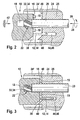
- FIG. 2 shows a section through the device in the region of the end face of the insert 10 and the in FIG. 1 not shown, divided at the front of the insert 10 Tool 24,24 'with its core 25 at the beginning of the screwing.
- the centering pin 22 according to the arrow 36 in FIG. 1 first pressed by spring force into the opening 18 and then offset under pressure according to the arrow 28 in the right direction.
- the insert 10 is locked in the mold not shown against the force exerted by the centering pin 22 axial pressure.
- the locking of the insert in the axial direction is indicated by an anchored arrow 42.
- a notch 38 and the core 25 of the tool 24, a projection 40 are provided on the insert 10, which together form an anti-rotation for the insert 10 when screwing and unscrewing the centering pin 22.
- the insert 10 is as out FIG. 2 seen, with its knob-shaped projections 19 still at a distance from the end face 48 of the core 25 of the tool 24.
- the contact pins 12 and 14 protrude already in recesses 44, 46 in the core 25 of the tool 24, whose dimensions correspond approximately to the dimensions of the contact pins so that they form a further anti-rotation and guide for the insert 10 during the screwing and Ausschraubvorgang, but the majority of the torsional forces is absorbed by the notch 38 and the projection 40.
- FIG. 3 shows the arrangement in the screwed-in state of the centering pin 22, that is in the casting position. From this representation, it can be clearly seen that by pressing the knob-shaped projections 19 of the insert 10 on the end face 48 of the tool core 25 ensures a secure and defined locking of the insert 10 and thereby again defined wall thicknesses of the encapsulation, not shown around the insert 10 around are ensured.
- FIG. 4 shows the Ausschraubvorgang the centering pin 22 from the opening 18 of the insert 10.
- the unscrewing of the mandrel 20 with the centering pin 22 again takes place through the ejector mechanism 30, not shown, which ejects the finished overmolded plug with the insert 10 and the two contact pins 12 and 14 from the mold after unscrewing the centering pin 22.
- the ejector mechanism 30 not shown, which ejects the finished overmolded plug with the insert 10 and the two contact pins 12 and 14 from the mold after unscrewing the centering pin 22.
- FIG. 5 schematically the sealing of the exit region of the mandrel 20 and the centering pin 22 is shown, which prevents the penetration of the potting compound in this area.
- the region of the end face 48 of the tool core 25 facing the insert 10 is provided with a crimping lip 50 integrally formed thereon, which completely surrounds the passage region of the mandrel 20 and is preferably of circular design.
- the Quetschlippe 50 can also be provided on the end face 16 of the insert 10 in the area around the opening 18 around.
- the Quetschlippe 50 consists of the material of the insert 10 and is optionally slightly deformable, in the formation of the Quetschlippe 50 on the tool core 25, it consists of the tool material, usually made of metal.
Landscapes
- Engineering & Computer Science (AREA)
- Manufacturing & Machinery (AREA)
- Mechanical Engineering (AREA)
- Moulds For Moulding Plastics Or The Like (AREA)
- Injection Moulding Of Plastics Or The Like (AREA)
Description
- Die Erfindung geht aus von einer Vorrichtung und einem Verfahren zur gießtechnischen Umhüllung eines Einlegeteils mit Kunststoff, insbesondere zur spritzgießtechnischen Umhüllung eines Einlegeteils eines vorzugsweise mehrpoligen Steckers mit thermoplastischem Kunststoff, nach dem Oberbegriff der Ansprüche 1 und 13. Ein derartiges Verfahren und eine zugehörige Spritzform sind aus der
DE 44 46 658 C2 bekannt. Das dort beschriebene Verfahren dient zur Herstellung eines zwei- oder mehrpoligen Steckers an elektrischen Leitern, deren abisolierte Enden mit Kontaktstiften versehen und in einem Halteteil fixiert sind, welches beim Spritzvorgang mittel eines in das Halteteil hineinreichenden Zentrierstiftes in der Spritzform zentriert ist. Wegen des unvermeidlichen Spiels zwischen dem Zentrierstift und der Führungsbohrung kann hierbei jedoch ein leichtes Verkippen und eine Schiefstellung des Einlegeteils nicht völlig vermieden werden, wodurch Undichtigkeiten und unterschiedliche, nicht definierte Wandstärken an der Umhüllung entstehen. - Aus der
JP-A-07124998 - Der Erfindung liegt die Aufgabe zugrunde, die vorgenannten Nachteile zu vermeiden durch eine exakte und spielfreie Anordnung des Einlegeteils in der Gießform um hierdurch insbesondere definierte Wandstärken der Umhüllung des Einlegeteils sicher zu stellen. Diese Aufgabe wird gelöst durch die kennzeichnenden Merkmale der Ansprüche 1 und 13.
- Als vorteilhaft hat es sich erwiesen, wenn der Zentrierstift an seinem dem Einlegeteil zugewandten Ende ein Gewinde zum Einschrauben in die Öffnung im Einlegeteil aufweist. Durch die Anbringung des Gewindes an einem metallischen Zentrierstift kann bei den meisten für derartige Einlegeteile verwendeten Materialien am Einlegeteil selbst auf ein Gegengewinde verzichtet werden. Dies gilt insbesondere, wenn das Gewinde selbstschneidend ausgebildet ist. Die Zentrierung und Arretierung des Zentrierstiftes in der Öffnung des Einlegeteils wird dabei noch weiter verbessert, wenn die Öffnung im Einlegeteil in Einschraubrichtung des Zentrierstiftes verjüngt ist. Zur Sicherstellung des Eingriffs des Zentrierstiftes in die vorzugsweise abgestufte und am Eingang verbreiterte Öffnung des Einlegeteils ist dieser zweckmäßigerweise in Achsrichtung federnd derart gelagert, dass er im geschlossenen Zustand der Gießform mit Vorspannung in die Öffnung eingreift.
- Ferner hat es sich als besonders vorteilhaft erwiesen, wenn auf der einem Kern des Werkzeugs zugewandten Stirnseite des Einlegeteils noppenförmige Vorsprünge ausgebildet sind zur Abstützung des Einlegeteils am Werkzeug im eingeschraubten Zustand des Zentrierstiftes. Hierdurch wird die Ausrichtung des Einlegeteils im Gießwerkzeug weiter verbessert, weil durch die noppenförmigen Vorsprünge eine definierte Abstützung des Einlegeteils am Werkzeug und hierdurch wiederum eine definierte Wandstärke der Umhüllung gesichert ist.
- Zur Abdichtung des Bereiches um den Zentrierstift herum gegen die eingebrachte Vergussmasse hat es sich weiterhin als zweckmäßig erwiesen, zwischen den Stirnseiten des Werkzeugs und des Einlegeteils um den Zentrierstift herum wenigstens eine Quetschlippe auszubilden, welche entweder am Werkzeug als metallische Quetschlippe oder am Einlegeteil aus dem hierfür verwendeten Material ausgebildet wird. Hierdurch erreicht man eine einwandfreie Abdichtung zur Vermeidung von Kunststoffrückständen am Werkzeug und/oder am Zentrierstift.
- Der Antrieb des Dornes und des Zentrierstiftes in Vorschubrichtung und in Drehrichtung erfolgt vorzugsweise durch die Auswurfmechanik der Gießeinrichtung. Hierdurch lässt sich zusätzlicher Aufwand für einen separaten Antrieb vermeiden.
- Weitere Einzelheiten und vorteilhafte Ausgestaltungen der Erfindung ergeben sich aus den Unteransprüchen sowie aus der Beschreibung und der Zeichnung eines Ausführungsbeispiels. Diese zeigt in
-
Figur 1 eine perspektivische Prinzipdarstellung einer erfindungsgemäßen Vorrichtung, in -
Figur 2 einen Schnitt durch die Vorrichtung im Bereich zwischen Einlegeteil und Werkzeug beim Schließen der Gießform, in -
Figur 3 einen Schnitt durch die Vorrichtung mit an das Werkzeug angepresstem Einlegeteil, in -
Figur 4 einen Schnitt durch die Vorrichtung vor dem Öffnen der Gießform während des Herausführens des Dornes mit dem Zentrierstift aus der Öffnung des Einlegeteils und in -
Figur 5 eine Darstellung der Werkzeugstirnfläche mit einer angeformten Quetschlippe im Bereich um den Austritt des Zentrierstiftes herum. - In
Figur 1 ist mit 10 ein Einlegeteil bezeichnet, welches hohl ausgebildet ist zur Aufnahme eines nicht dargestellten elektrischen Kabels, dessen Adern im Inneren des Einlegeteils 10 mit zwei Kontaktpins 12 und 14 verbunden sind, die aus der Stirnseite 16 des Einlegeteils herausragen. Das Einlegeteil 10 ist aus thermoplastischem oder duroplastischem Kunststoff hergestellt und weist auf seiner Stirnseite 16 eine abgestufte Öffnung 18 sowie vier noppenartige Vorsprünge 19 auf. Das Einlegeteil 10 ist nach dem Umgießen Teil eines zweipoligen Steckers, welcher in einer in den folgenden Figuren nur teilweise dargestellten Gießform durch Spritzgießen mit thermoplastischem Kunststoff umhüllt wird. Auf die Darstellung des fertigen Steckers mit der Umhüllung ist in der Zeichnung zwecks klarerer Darstellung der erfindungswesentlichen Teile verzichtet worden. - Dem Einlegeteil 10 gegenüber ist ein Dorn 20 angeordnet mit einem Zentrierstift 22 an seinem vorderen Ende, welcher in dem in
Figur 1 nicht dargestellten Kern des Werkzeugs längsverschiebbar und drehbar geführt ist. Die Längsverschiebung des Dorns 20 ist durch einen Pfeil 26, die Verdrehung durch einen Pfeil 28 angedeutet. Den Antrieb für den Dorn 20 mit dem Zentrierstift 22 bewirkt die inFigur 1 nur als Baueinheit dargestellte Auswurfmechanik 30 der Gießvorrichtung. - Die Anpressung des Einlegeteils 10 an das Werkzeug erfolgt durch Einschrauben des Zentrierstiftes 22 in die Öffnung 18 im Einlegeteil 10. Hierzu besitzt der Zentrierstift 22 ein selbstschneidendes Gewinde 32 mit messerförmigen Erhebungen 34, mittels derer der Zentrierstift 22 bei Rechtsdrehung in die nach innen verjüngte Öffnung 18 im Einlegeteil 10 einschraubbar und bei Linksdrehung herausschraubbar ist. Die Tiefe der Öffnung 18 entspricht mindestens dem Anpressweg des Einlegeteils 10 zum Werkzeug hin. Der Dorn 20 mit dem Zentrierstift 22 steht weiterhin unter axialer Vorspannung zum Einführen und Anpressen des Zentrierstiftes 22 in die Öffnung 18. Die axiale Vorspannung ist in
Figur 1 durch einen Pfeil 36 mit Federvorspannung dargestellt. Der Verdrehwinkel des Zentrierstiftes 22 beim Ein- und Ausschrauben beträgt 30°-180°, vorzugsweise etwa 45° mit entsprechend steil verlaufenden Gewindegängen. -
Figur 2 zeigt einen Schnitt durch die Vorrichtung im Bereich der Stirnseite des Einlegeteils 10 und des inFigur 1 nicht dargestellten, an der Stirnseite des Einlegeteils 10 geteilten Werkzeugs 24,24' mit seinem Kern 25 zu Beginn des Einschraubvorgangs. Hierbei wird der Zentrierstift 22 entsprechend dem Pfeil 36 inFigur 1 zunächst durch Federkraft in die Öffnung 18 hineingedrückt und dann unter Druck entsprechend dem Pfeil 28 in Rechtsdrehung versetzt. Das Einlegeteil 10 ist in der nicht weiter dargestellten Gießform arretiert gegen den von dem Zentrierstift 22 ausgeübten axialen Druck. Die Arretierung des Einlegeteils in axialer Richtung ist durch einen verankerten Pfeil 42 angedeutet. Außerdem sind am Einlegeteil 10 eine Einkerbung 38 und am Kern 25 des Werkzeugs 24 ein Vorsprung 40 vorgesehen, welche gemeinsam eine Verdrehsicherung für das Einlegeteil 10 beim Ein- und Ausschrauben des Zentrierstiftes 22 bilden. - Zu Beginn des Prozesses befindet sich das Einlegeteil 10, wie aus
Figur 2 ersichtlich, mit seinen noppenförmigen Vorsprüngen 19 noch im Abstand von der Stirnseite 48 des Kerns 25 des Werkzeuges 24. Die Kontaktpins 12 und 14 ragen dabei schon in Aussparungen 44, 46 im Kern 25 des Werkzeugs 24 hinein, deren Abmessungen etwa den Abmessungen der Kontaktpins entsprechen, so dass diese eine weitere Verdrehsicherung und Führung für das Einlegeteil 10 beim Ein- und Ausschraubvorgang bilden, wobei jedoch der Hauptteil der Verdrehkräfte durch die Einkerbung 38 und den Vorsprung 40 aufgenommen wird. -
Figur 3 zeigt die Anordnung im eingeschraubten Zustand des Zentrierstiftes 22, das heißt in der Gießposition. Aus dieser Darstellung ist deutlich zu erkennen, dass durch die Anpressung der noppenförmigen Vorsprünge 19 des Einlegeteils 10 an die Stirnfläche 48 des Werkzeugkerns 25 eine sichere und definierte Arretierung des Einlegeteils 10 gewährleistet und hierdurch wiederum definierte Wandstärken des nicht dargestellten Vergusses rund um das Einlegeteil 10 herum sicher gestellt sind. -
Figur 4 zeigt den Ausschraubvorgang des Zentrierstiftes 22 aus der Öffnung 18 des Einlegeteils 10. Das Ausschrauben des Dornes 20 mit dem Zentrierstift 22 erfolgt wiederum durch die nicht dargestellte Auswurfmechanik 30, welche nach dem Ausschrauben des Zentrierstiftes 22 den fertig umspritzten Stecker mit dem Einlegeteil 10 und den beiden Kontaktpins 12 und 14 aus der Gießform auswirft. Auf die vollständige Darstellung der Gießform mit dem die Außenkontur des Steckers bestimmenden Teil des Werkzeugs ist in den Zeichnungen zugunsten einer klareren Darstellung der erfindungswesentlichen Teile verzichtet worden. - In
Figur 5 ist schematisch die Abdichtung des Austrittsbereiches des Dorns 20 und des Zentrierstiftes 22 dargestellt, welche das Eindringen der Vergussmasse in diesen Bereich verhindert. Hierzu ist der dem Einlegeteil 10 zugewandte Bereich der Stirnseite 48 des Werkzeugkerns 25 mit einer an diesen angeformten Quetschlippe 50 versehen, welche den Durchtrittsbereich des Dorns 20 vollständig umgibt und vorzugsweise kreisförmig ausgebildet ist. Die Quetschlippe 50 kann jedoch auch an der Stirnfläche 16 des Einlegeteils 10 vorgesehen werden im Bereich um die Öffnung 18 herum. In diesem Fall besteht die Quetschlippe 50 aus dem Material des Einlegeteils 10 und ist gegebenenfalls geringfügig verformbar, bei der Ausbildung der Quetschlippe 50 am Werkzeugkern 25 besteht sie aus dem Werkzeugmaterial, in der Regel aus Metall.
Claims (13)
- Vorrichtung zur gießtechnischen Umhüllung eines Einlegeteils mit Kunststoff, insbesondere zur spritzgießtechnischen Umhüllung eines Einlegeteils eines vorzugsweise mehrpoligen Steckers mit thermoplastischem Kunststoff, wobei das Einlegeteil in eine Gießform eingebracht wird, welche ein die Kontur der Umhüllung bestimmendes Werkzeug mit einem Kern und einem darin längsverschiebbaren Dorn aufweist, der an seinem dem Einlegeteil zugewandten Ende einen in das Einlegeteil einbringbaren Zentrierstift besitzt, wobei der Zentrierstift (22) zusammen mit dem Dorn (20) im Werkzeug (24,25) verdrehbar und längsverschiebbar gehalten und in einer Öffnung (18) im Einlegeteil (10) verschraubbar ist, wobei der Zentrierstift (22) an seinem dem Einlegeteil (10) zugewandten Ende ein Gewinde (32) zum Einschrauben in die Öffnung (18) im Einlegeteil (10) aufweist, dadurch gekennzeichnet, dass das Gewinde (32) selbstschneidend ausgebildet ist.
- Vorrichtung nach einem der vorhergehenden Ansprüche, dadurch gekennzeichnet, dass die Öffnung (18) im Einlegeteil (10) in Einschraubrichtung des Zentrierstiftes (22) verjüngt ist.
- Vorrichtung nach einem der vorhergehenden Ansprüche, dadurch gekennzeichnet, dass der Zentrierstift (22) in Einschraub- und Ausschraubrichtung jeweils um 30° bis 180°, vorzugsweise um ca. 45°, verdrehbar ist.
- Vorrichtung nach einem der vorhergehenden Ansprüche, dadurch gekennzeichnet, dass der Dorn (20) mit dem Zentrierstift (22) im Werkzeug (24,25) in Achsrichtung federnd gelagert ist.
- Vorrichtung nach einem der vorhergehenden Ansprüche, dadurch gekennzeichnet, dass auf der dem Werkzeug (24,25) zugewandten Stirnseite (16) des Einlegeteils (10) noppenförmige Vorsprünge (19) ausgebildet sind zur Abstützung des Einlegeteils (10) am Kern (25) des Werkzeugs (24) im eingeschraubten Zustand des Zentrierstiftes (22).
- Vorrichtung nach einem der vorhergehenden Ansprüche dadurch gekennzeichnet, dass auf der dem Einlegeteil (10) zugewandten Stirnseite (48) des Werkzeugs (24,25) um den Zentrierstift (22) herum wenigstens eine Quetschlippe (50) ausgebildet ist.
- Vorrichtung nach einem der vorhergehenden Ansprüche, dadurch gekennzeichnet, dass das Werkzeug (24,25) an seiner dem Einlegeteil (10) zugewandten Stirnseite (48) wenigstens eine Aussparung (44,46) besitzt für die Aufnahme wenigstens eines Kontaktpins (12,14) an einem zur Herstellung eines Steckers ausgebildeten Einlegeteil (10).
- Vorrichtung nach einem der vorhergehenden Ansprüche, dadurch gekennzeichnet, dass der Dorn (20) und der Zentrierstift (22) durch eine Auswurfmechanik (30) der Gießeinrichtung verdrehbar (28) und längsverschiebbar (26) sind.
- Vorrichtung nach einem der vorhergehenden Ansprüche, dadurch gekennzeichnet, dass das Einlegeteil (10) am Werkzeug (24,25) durch eine Verdrehsicherung (38,40) arretierbar ist.
- Verfahren zur gießtechnischen Umhüllung eines Einlegeteils mit Kunststoff, insbesondere zur spritzgießtechnischen Umhüllung eines Einlegeteils eines vorzugsweise mehrpoligen Steckers mit thermoplastischem Kunststoff, wobei das Einlegeteil in eine Gießform eingebracht wird, welche ein die Kontur der Umhüllung bestimmendes Werkzeug mit einem Kern und einem darin längsverschiebbaren Dorn aufweist, der an seinem dem Einlegeteil zugewandten Ende einen in das Einlegeteil einbringbaren Zentrierstift besitzt, wobei das Einlegeteil (10) durch Einschrauben des Zentrierstiftes (22) an das Werkzeug (24,25) anpressbar ist, dadurch gekennzeichnet, dass der Zentrierstift (22) mittels selbstschneidender Gewindevorsprünge (32,34) an seinem dem Einlegeteil (10) zugewandten Ende in eine sich nach innen verjüngende Öffnung (18) im Einlegeteil (10) einschraubbar ist.
- Verfahren nach Anspruch 10, dadurch gekennzeichnet, dass das Einlegeteil (10) mit noppenförmigen Vorsprüngen (19) auf seiner dem Werkzeug (24,25) zugewandten Stirnseite (16) beim Einschrauben des Zentrierstiftes (22) mit definiertem Abstand entsprechend der vorgesehenen Wandstärke an das Werkzeug (24) anpressbar ist.
- Verfahren nach Anspruch 10 oder 11, dadurch gekennzeichnet, dass das Einlegeteil (10) gegenüber dem Werkzeug (24,25) durch Aussparungen (38;44,46) und vorspringende Teile (12,14;40) verdrehsicher gehalten wird.
- Verfahren nach einem der Ansprüche 10 bis 12, dadurch gekennzeichnet, dass der Zentrierstift (22) beim Schließen der Gießform (24,24',25) federnd in die Öffnung (18) im Einlegeteil (10) hineingedrückt wird.
Priority Applications (1)
| Application Number | Priority Date | Filing Date | Title |
|---|---|---|---|
| PL04024152T PL1541316T3 (pl) | 2003-12-10 | 2004-10-09 | Urządzenie i sposób odlewowego osłaniania wkładki tworzywem sztucznym |
Applications Claiming Priority (2)
| Application Number | Priority Date | Filing Date | Title |
|---|---|---|---|
| DE10357647A DE10357647A1 (de) | 2003-12-10 | 2003-12-10 | Vorrichtung und Verfahren zur gießtechnischen Umhüllung eines Einlegeteils mit Kunststoff |
| DE10357647 | 2003-12-10 |
Publications (2)
| Publication Number | Publication Date |
|---|---|
| EP1541316A1 EP1541316A1 (de) | 2005-06-15 |
| EP1541316B1 true EP1541316B1 (de) | 2008-04-23 |
Family
ID=34485286
Family Applications (1)
| Application Number | Title | Priority Date | Filing Date |
|---|---|---|---|
| EP04024152A Expired - Lifetime EP1541316B1 (de) | 2003-12-10 | 2004-10-09 | Vorrichtung und Verfahren zur giesstechnischen Umhüllung eines Einlegeteils mit Kunststoff |
Country Status (4)
| Country | Link |
|---|---|
| EP (1) | EP1541316B1 (de) |
| AT (1) | ATE393005T1 (de) |
| DE (2) | DE10357647A1 (de) |
| PL (1) | PL1541316T3 (de) |
Families Citing this family (4)
| Publication number | Priority date | Publication date | Assignee | Title |
|---|---|---|---|---|
| DE102011085032A1 (de) | 2011-10-21 | 2013-04-25 | Robert Bosch Gmbh | Vorrichtung zum Halten eines mit Kunststoff zu umhüllenden Bauelements und Verfahren zum Umhüllen eines Bauelements |
| DE102014206088A1 (de) * | 2014-03-31 | 2015-10-01 | Böllhoff Verbindungstechnik GmbH | Gussform, Einlegeteil für eine Gussform, ein Gussteil und Gussverfahren dafür |
| DE102014222908A1 (de) | 2014-11-10 | 2016-05-12 | Böllhoff Verbindungstechnik GmbH | Gussform, Einlegeteil für eine Gussform, ein Gussteil und Gussverfahren dafür |
| CN106808673B (zh) * | 2017-03-21 | 2022-11-01 | 东莞星海丰电子有限公司 | 硅胶套成型模具快速翻转定位方法及成型模芯翻转机构 |
Family Cites Families (4)
| Publication number | Priority date | Publication date | Assignee | Title |
|---|---|---|---|---|
| JP2968989B2 (ja) * | 1990-11-05 | 1999-11-02 | 智史 井上 | 継手内部成型装置 |
| DE4328240C2 (de) * | 1993-08-19 | 1997-07-17 | Siemens Ag | Verfahren zur Herstellung eines Steckers und Spritzgießform zur Durchführung des Verfahrens |
| JP3404832B2 (ja) * | 1993-10-15 | 2003-05-12 | 住友電装株式会社 | コネクタの製造方法及びコネクタ |
| JP3010991B2 (ja) * | 1993-10-29 | 2000-02-21 | 豊田合成株式会社 | インサート付き樹脂成形品の成形型 |
-
2003
- 2003-12-10 DE DE10357647A patent/DE10357647A1/de not_active Withdrawn
-
2004
- 2004-10-09 AT AT04024152T patent/ATE393005T1/de not_active IP Right Cessation
- 2004-10-09 DE DE502004006900T patent/DE502004006900D1/de not_active Expired - Lifetime
- 2004-10-09 EP EP04024152A patent/EP1541316B1/de not_active Expired - Lifetime
- 2004-10-09 PL PL04024152T patent/PL1541316T3/pl unknown
Also Published As
| Publication number | Publication date |
|---|---|
| EP1541316A1 (de) | 2005-06-15 |
| DE502004006900D1 (de) | 2008-06-05 |
| PL1541316T3 (pl) | 2008-09-30 |
| ATE393005T1 (de) | 2008-05-15 |
| DE10357647A1 (de) | 2005-07-07 |
Similar Documents
| Publication | Publication Date | Title |
|---|---|---|
| DE102010064071B3 (de) | Klemmring, Kabelverschraubung und Verfahren zum Montieren einer Kabelverschraubung | |
| EP0816151A1 (de) | Kraftstoffbehälter | |
| EP2505332B1 (de) | Kunststoffkörper und System zur Herstellung eines Kunststoffkörpers | |
| DE10350763A1 (de) | Koaxialkabel mit Winkelsteckverbindung | |
| EP2377665B1 (de) | Vorrichtung und Verfahren zum Spritzgiessen eines mindestens einen Hohlraum aufweisenden Formteils | |
| EP2849826B1 (de) | Verfahren zur herstellung eines spritzenzylinders für medizinische zwecke sowie eine vorrichtung zur durchführung des verfahrens | |
| DE3134602C2 (de) | Verfahren und Vorrichtung zur Herstellung einer Tube mit Verschlußkappe aus Kunststoff | |
| EP3660995A1 (de) | Integral hergestellte kabelverschraubung | |
| DE2950853C2 (de) | Koppelvorrichtung mit Druckkörpern für in Stecker gefaßte Lichtleitfasern | |
| DE60320131T2 (de) | Verfahren und vorrichtung zur herstellung eines rechtwinkligen steckanschlusses für rohrleitungen | |
| EP1541316A1 (de) | Vorrichtung und Verfahren zur giesstechnischen Umhüllung eines Einlegeteils mit Kunststoff | |
| DE10251644B4 (de) | Hahn | |
| DE10215735B4 (de) | LWL-Stecker-Kabelanordnung | |
| DE1163527B (de) | Verfahren zur Herstellung einer aus thermoplastischem Kunststoff bestehenden Verschlusskappe | |
| DE102008005494B4 (de) | Steckverbindung mit einer Abdichtbarriere und Herstellungsverfahren einer derartigen Steckverbindung | |
| EP0529475A2 (de) | Zugfeste Kabel-Endabschlussdichtung | |
| DE102011085032A1 (de) | Vorrichtung zum Halten eines mit Kunststoff zu umhüllenden Bauelements und Verfahren zum Umhüllen eines Bauelements | |
| DE102005015242B4 (de) | Heißkanalverteilerblock für den Anschluß an eine Spritzgießmaschine | |
| EP4218659B1 (de) | Dentalkartusche | |
| EP0732184A1 (de) | Glühlampenschraubfassung sowie Spritzgusswerkzeug und Verfahren zu ihrer Herstellung | |
| DE102023203712B3 (de) | Vorrichtung zum Herstellen eines Innenverkleidungsteils | |
| DE2409144A1 (de) | Selbstschneidender gewindebolzen mit sicherungsvorrichtung | |
| DE2457564A1 (de) | Elektrischer stecker | |
| DE2534375C2 (de) | Stiftförmige Vorrichtung zum federnden Verspannen zweier Bauteile | |
| DE2405313A1 (de) | Elektrische verbindungseinrichtung |
Legal Events
| Date | Code | Title | Description |
|---|---|---|---|
| PUAI | Public reference made under article 153(3) epc to a published international application that has entered the european phase |
Free format text: ORIGINAL CODE: 0009012 |
|
| AK | Designated contracting states |
Kind code of ref document: A1 Designated state(s): AT BE BG CH CY CZ DE DK EE ES FI FR GB GR HU IE IT LI LU MC NL PL PT RO SE SI SK TR |
|
| AX | Request for extension of the european patent |
Extension state: AL HR LT LV MK |
|
| 17P | Request for examination filed |
Effective date: 20051215 |
|
| AKX | Designation fees paid |
Designated state(s): AT BE BG CH CY CZ DE DK EE ES FI FR GB GR HU IE IT LI LU MC NL PL PT RO SE SI SK TR |
|
| 17Q | First examination report despatched |
Effective date: 20061121 |
|
| GRAP | Despatch of communication of intention to grant a patent |
Free format text: ORIGINAL CODE: EPIDOSNIGR1 |
|
| GRAS | Grant fee paid |
Free format text: ORIGINAL CODE: EPIDOSNIGR3 |
|
| GRAA | (expected) grant |
Free format text: ORIGINAL CODE: 0009210 |
|
| AK | Designated contracting states |
Kind code of ref document: B1 Designated state(s): AT BE BG CH CY CZ DE DK EE ES FI FR GB GR HU IE IT LI LU MC NL PL PT RO SE SI SK TR |
|
| REG | Reference to a national code |
Ref country code: GB Ref legal event code: FG4D Free format text: NOT ENGLISH |
|
| REG | Reference to a national code |
Ref country code: CH Ref legal event code: EP |
|
| REF | Corresponds to: |
Ref document number: 502004006900 Country of ref document: DE Date of ref document: 20080605 Kind code of ref document: P |
|
| REG | Reference to a national code |
Ref country code: IE Ref legal event code: FG4D Free format text: LANGUAGE OF EP DOCUMENT: GERMAN |
|
| REG | Reference to a national code |
Ref country code: RO Ref legal event code: EPE |
|
| PG25 | Lapsed in a contracting state [announced via postgrant information from national office to epo] |
Ref country code: SI Free format text: LAPSE BECAUSE OF FAILURE TO SUBMIT A TRANSLATION OF THE DESCRIPTION OR TO PAY THE FEE WITHIN THE PRESCRIBED TIME-LIMIT Effective date: 20080423 |
|
| REG | Reference to a national code |
Ref country code: PL Ref legal event code: T3 |
|
| NLV1 | Nl: lapsed or annulled due to failure to fulfill the requirements of art. 29p and 29m of the patents act | ||
| PG25 | Lapsed in a contracting state [announced via postgrant information from national office to epo] |
Ref country code: NL Free format text: LAPSE BECAUSE OF FAILURE TO SUBMIT A TRANSLATION OF THE DESCRIPTION OR TO PAY THE FEE WITHIN THE PRESCRIBED TIME-LIMIT Effective date: 20080423 Ref country code: ES Free format text: LAPSE BECAUSE OF FAILURE TO SUBMIT A TRANSLATION OF THE DESCRIPTION OR TO PAY THE FEE WITHIN THE PRESCRIBED TIME-LIMIT Effective date: 20080803 Ref country code: FI Free format text: LAPSE BECAUSE OF FAILURE TO SUBMIT A TRANSLATION OF THE DESCRIPTION OR TO PAY THE FEE WITHIN THE PRESCRIBED TIME-LIMIT Effective date: 20080423 Ref country code: BG Free format text: LAPSE BECAUSE OF FAILURE TO SUBMIT A TRANSLATION OF THE DESCRIPTION OR TO PAY THE FEE WITHIN THE PRESCRIBED TIME-LIMIT Effective date: 20080723 Ref country code: PT Free format text: LAPSE BECAUSE OF FAILURE TO SUBMIT A TRANSLATION OF THE DESCRIPTION OR TO PAY THE FEE WITHIN THE PRESCRIBED TIME-LIMIT Effective date: 20080923 |
|
| REG | Reference to a national code |
Ref country code: IE Ref legal event code: FD4D |
|
| REG | Reference to a national code |
Ref country code: HU Ref legal event code: AG4A Ref document number: E004060 Country of ref document: HU |
|
| PG25 | Lapsed in a contracting state [announced via postgrant information from national office to epo] |
Ref country code: SE Free format text: LAPSE BECAUSE OF FAILURE TO SUBMIT A TRANSLATION OF THE DESCRIPTION OR TO PAY THE FEE WITHIN THE PRESCRIBED TIME-LIMIT Effective date: 20080723 Ref country code: IE Free format text: LAPSE BECAUSE OF FAILURE TO SUBMIT A TRANSLATION OF THE DESCRIPTION OR TO PAY THE FEE WITHIN THE PRESCRIBED TIME-LIMIT Effective date: 20080423 Ref country code: DK Free format text: LAPSE BECAUSE OF FAILURE TO SUBMIT A TRANSLATION OF THE DESCRIPTION OR TO PAY THE FEE WITHIN THE PRESCRIBED TIME-LIMIT Effective date: 20080423 Ref country code: CZ Free format text: LAPSE BECAUSE OF FAILURE TO SUBMIT A TRANSLATION OF THE DESCRIPTION OR TO PAY THE FEE WITHIN THE PRESCRIBED TIME-LIMIT Effective date: 20080423 |
|
| ET | Fr: translation filed | ||
| PG25 | Lapsed in a contracting state [announced via postgrant information from national office to epo] |
Ref country code: SK Free format text: LAPSE BECAUSE OF FAILURE TO SUBMIT A TRANSLATION OF THE DESCRIPTION OR TO PAY THE FEE WITHIN THE PRESCRIBED TIME-LIMIT Effective date: 20080423 |
|
| PLBE | No opposition filed within time limit |
Free format text: ORIGINAL CODE: 0009261 |
|
| STAA | Information on the status of an ep patent application or granted ep patent |
Free format text: STATUS: NO OPPOSITION FILED WITHIN TIME LIMIT |
|
| 26N | No opposition filed |
Effective date: 20090126 |
|
| BERE | Be: lapsed |
Owner name: ROBERT BOSCH G.M.B.H. Effective date: 20081031 |
|
| PG25 | Lapsed in a contracting state [announced via postgrant information from national office to epo] |
Ref country code: EE Free format text: LAPSE BECAUSE OF FAILURE TO SUBMIT A TRANSLATION OF THE DESCRIPTION OR TO PAY THE FEE WITHIN THE PRESCRIBED TIME-LIMIT Effective date: 20080423 |
|
| PG25 | Lapsed in a contracting state [announced via postgrant information from national office to epo] |
Ref country code: MC Free format text: LAPSE BECAUSE OF NON-PAYMENT OF DUE FEES Effective date: 20081031 |
|
| REG | Reference to a national code |
Ref country code: CH Ref legal event code: PL |
|
| PG25 | Lapsed in a contracting state [announced via postgrant information from national office to epo] |
Ref country code: IT Free format text: LAPSE BECAUSE OF FAILURE TO SUBMIT A TRANSLATION OF THE DESCRIPTION OR TO PAY THE FEE WITHIN THE PRESCRIBED TIME-LIMIT Effective date: 20080423 |
|
| PG25 | Lapsed in a contracting state [announced via postgrant information from national office to epo] |
Ref country code: BE Free format text: LAPSE BECAUSE OF NON-PAYMENT OF DUE FEES Effective date: 20081031 |
|
| PG25 | Lapsed in a contracting state [announced via postgrant information from national office to epo] |
Ref country code: LI Free format text: LAPSE BECAUSE OF NON-PAYMENT OF DUE FEES Effective date: 20081031 Ref country code: CH Free format text: LAPSE BECAUSE OF NON-PAYMENT OF DUE FEES Effective date: 20081031 |
|
| PG25 | Lapsed in a contracting state [announced via postgrant information from national office to epo] |
Ref country code: AT Free format text: LAPSE BECAUSE OF NON-PAYMENT OF DUE FEES Effective date: 20081009 |
|
| PG25 | Lapsed in a contracting state [announced via postgrant information from national office to epo] |
Ref country code: LU Free format text: LAPSE BECAUSE OF NON-PAYMENT OF DUE FEES Effective date: 20081009 Ref country code: CY Free format text: LAPSE BECAUSE OF FAILURE TO SUBMIT A TRANSLATION OF THE DESCRIPTION OR TO PAY THE FEE WITHIN THE PRESCRIBED TIME-LIMIT Effective date: 20080423 |
|
| PG25 | Lapsed in a contracting state [announced via postgrant information from national office to epo] |
Ref country code: TR Free format text: LAPSE BECAUSE OF FAILURE TO SUBMIT A TRANSLATION OF THE DESCRIPTION OR TO PAY THE FEE WITHIN THE PRESCRIBED TIME-LIMIT Effective date: 20080423 |
|
| PG25 | Lapsed in a contracting state [announced via postgrant information from national office to epo] |
Ref country code: GR Free format text: LAPSE BECAUSE OF FAILURE TO SUBMIT A TRANSLATION OF THE DESCRIPTION OR TO PAY THE FEE WITHIN THE PRESCRIBED TIME-LIMIT Effective date: 20080724 |
|
| REG | Reference to a national code |
Ref country code: FR Ref legal event code: PLFP Year of fee payment: 12 |
|
| REG | Reference to a national code |
Ref country code: FR Ref legal event code: PLFP Year of fee payment: 13 |
|
| REG | Reference to a national code |
Ref country code: FR Ref legal event code: PLFP Year of fee payment: 14 |
|
| REG | Reference to a national code |
Ref country code: FR Ref legal event code: PLFP Year of fee payment: 15 |
|
| PGFP | Annual fee paid to national office [announced via postgrant information from national office to epo] |
Ref country code: AT Payment date: 20181121 Year of fee payment: 16 |
|
| PGFP | Annual fee paid to national office [announced via postgrant information from national office to epo] |
Ref country code: FR Payment date: 20181023 Year of fee payment: 15 Ref country code: GB Payment date: 20181025 Year of fee payment: 15 |
|
| PG25 | Lapsed in a contracting state [announced via postgrant information from national office to epo] |
Ref country code: HU Free format text: LAPSE BECAUSE OF NON-PAYMENT OF DUE FEES Effective date: 20191010 |
|
| GBPC | Gb: european patent ceased through non-payment of renewal fee |
Effective date: 20191009 |
|
| PG25 | Lapsed in a contracting state [announced via postgrant information from national office to epo] |
Ref country code: FR Free format text: LAPSE BECAUSE OF NON-PAYMENT OF DUE FEES Effective date: 20191031 Ref country code: GB Free format text: LAPSE BECAUSE OF NON-PAYMENT OF DUE FEES Effective date: 20191009 |
|
| PGFP | Annual fee paid to national office [announced via postgrant information from national office to epo] |
Ref country code: RO Payment date: 20200928 Year of fee payment: 17 |
|
| PGFP | Annual fee paid to national office [announced via postgrant information from national office to epo] |
Ref country code: PL Payment date: 20200928 Year of fee payment: 17 |
|
| PG25 | Lapsed in a contracting state [announced via postgrant information from national office to epo] |
Ref country code: RO Free format text: LAPSE BECAUSE OF NON-PAYMENT OF DUE FEES Effective date: 20211009 |
|
| PGFP | Annual fee paid to national office [announced via postgrant information from national office to epo] |
Ref country code: DE Payment date: 20221215 Year of fee payment: 19 |
|
| PG25 | Lapsed in a contracting state [announced via postgrant information from national office to epo] |
Ref country code: PL Free format text: LAPSE BECAUSE OF NON-PAYMENT OF DUE FEES Effective date: 20211009 |
|
| REG | Reference to a national code |
Ref country code: DE Ref legal event code: R119 Ref document number: 502004006900 Country of ref document: DE |
|
| PG25 | Lapsed in a contracting state [announced via postgrant information from national office to epo] |
Ref country code: DE Free format text: LAPSE BECAUSE OF NON-PAYMENT OF DUE FEES Effective date: 20240501 |