EP1541303B1 - Method of cutting multilayer body - Google Patents
Method of cutting multilayer body Download PDFInfo
- Publication number
- EP1541303B1 EP1541303B1 EP20030771360 EP03771360A EP1541303B1 EP 1541303 B1 EP1541303 B1 EP 1541303B1 EP 20030771360 EP20030771360 EP 20030771360 EP 03771360 A EP03771360 A EP 03771360A EP 1541303 B1 EP1541303 B1 EP 1541303B1
- Authority
- EP
- European Patent Office
- Prior art keywords
- multilayer structure
- cutting
- layer
- cutter
- push
- Prior art date
- Legal status (The legal status is an assumption and is not a legal conclusion. Google has not performed a legal analysis and makes no representation as to the accuracy of the status listed.)
- Expired - Lifetime
Links
- 238000005520 cutting process Methods 0.000 title claims abstract description 51
- 238000000034 method Methods 0.000 title claims abstract description 34
- 229920005989 resin Polymers 0.000 claims abstract description 94
- 239000011347 resin Substances 0.000 claims abstract description 94
- QVGXLLKOCUKJST-UHFFFAOYSA-N atomic oxygen Chemical compound [O] QVGXLLKOCUKJST-UHFFFAOYSA-N 0.000 claims description 16
- 229910052760 oxygen Inorganic materials 0.000 claims description 16
- 239000001301 oxygen Substances 0.000 claims description 16
- 239000007789 gas Substances 0.000 claims description 13
- 239000000463 material Substances 0.000 claims description 7
- 239000003795 chemical substances by application Substances 0.000 claims description 5
- 150000002505 iron Chemical class 0.000 claims description 5
- 238000002844 melting Methods 0.000 claims description 5
- 230000008018 melting Effects 0.000 claims description 5
- 239000010410 layer Substances 0.000 description 149
- 238000000465 moulding Methods 0.000 description 19
- NJPPVKZQTLUDBO-UHFFFAOYSA-N novaluron Chemical compound C1=C(Cl)C(OC(F)(F)C(OC(F)(F)F)F)=CC=C1NC(=O)NC(=O)C1=C(F)C=CC=C1F NJPPVKZQTLUDBO-UHFFFAOYSA-N 0.000 description 9
- 229920002292 Nylon 6 Polymers 0.000 description 6
- 238000010008 shearing Methods 0.000 description 6
- XEEYBQQBJWHFJM-UHFFFAOYSA-N Iron Chemical compound [Fe] XEEYBQQBJWHFJM-UHFFFAOYSA-N 0.000 description 4
- 239000003054 catalyst Substances 0.000 description 4
- 230000001590 oxidative effect Effects 0.000 description 4
- -1 polypropylene group Polymers 0.000 description 4
- 150000003624 transition metals Chemical group 0.000 description 4
- GVNWZKBFMFUVNX-UHFFFAOYSA-N Adipamide Chemical compound NC(=O)CCCCC(N)=O GVNWZKBFMFUVNX-UHFFFAOYSA-N 0.000 description 3
- 229920001577 copolymer Polymers 0.000 description 3
- 238000003780 insertion Methods 0.000 description 3
- 230000037431 insertion Effects 0.000 description 3
- 229910052751 metal Inorganic materials 0.000 description 3
- 239000002184 metal Substances 0.000 description 3
- 239000002344 surface layer Substances 0.000 description 3
- 229920005992 thermoplastic resin Polymers 0.000 description 3
- PXHVJJICTQNCMI-UHFFFAOYSA-N Nickel Chemical compound [Ni] PXHVJJICTQNCMI-UHFFFAOYSA-N 0.000 description 2
- 239000004952 Polyamide Substances 0.000 description 2
- 239000005030 aluminium foil Substances 0.000 description 2
- 150000001875 compounds Chemical class 0.000 description 2
- 230000006835 compression Effects 0.000 description 2
- 238000007906 compression Methods 0.000 description 2
- 238000001816 cooling Methods 0.000 description 2
- 239000005038 ethylene vinyl acetate Substances 0.000 description 2
- 229910052742 iron Inorganic materials 0.000 description 2
- JEIPFZHSYJVQDO-UHFFFAOYSA-N iron(III) oxide Inorganic materials O=[Fe]O[Fe]=O JEIPFZHSYJVQDO-UHFFFAOYSA-N 0.000 description 2
- 238000002156 mixing Methods 0.000 description 2
- 230000002093 peripheral effect Effects 0.000 description 2
- 229920001200 poly(ethylene-vinyl acetate) Polymers 0.000 description 2
- 229920002647 polyamide Polymers 0.000 description 2
- 229920000642 polymer Polymers 0.000 description 2
- 238000007127 saponification reaction Methods 0.000 description 2
- 239000002356 single layer Substances 0.000 description 2
- 238000007666 vacuum forming Methods 0.000 description 2
- 229910000906 Bronze Inorganic materials 0.000 description 1
- OKTJSMMVPCPJKN-UHFFFAOYSA-N Carbon Chemical group [C] OKTJSMMVPCPJKN-UHFFFAOYSA-N 0.000 description 1
- VYZAMTAEIAYCRO-UHFFFAOYSA-N Chromium Chemical compound [Cr] VYZAMTAEIAYCRO-UHFFFAOYSA-N 0.000 description 1
- RYGMFSIKBFXOCR-UHFFFAOYSA-N Copper Chemical compound [Cu] RYGMFSIKBFXOCR-UHFFFAOYSA-N 0.000 description 1
- JOYRKODLDBILNP-UHFFFAOYSA-N Ethyl urethane Chemical compound CCOC(N)=O JOYRKODLDBILNP-UHFFFAOYSA-N 0.000 description 1
- PWHULOQIROXLJO-UHFFFAOYSA-N Manganese Chemical compound [Mn] PWHULOQIROXLJO-UHFFFAOYSA-N 0.000 description 1
- 239000004793 Polystyrene Substances 0.000 description 1
- BQCADISMDOOEFD-UHFFFAOYSA-N Silver Chemical compound [Ag] BQCADISMDOOEFD-UHFFFAOYSA-N 0.000 description 1
- ATJFFYVFTNAWJD-UHFFFAOYSA-N Tin Chemical compound [Sn] ATJFFYVFTNAWJD-UHFFFAOYSA-N 0.000 description 1
- RTAQQCXQSZGOHL-UHFFFAOYSA-N Titanium Chemical compound [Ti] RTAQQCXQSZGOHL-UHFFFAOYSA-N 0.000 description 1
- QCWXUUIWCKQGHC-UHFFFAOYSA-N Zirconium Chemical compound [Zr] QCWXUUIWCKQGHC-UHFFFAOYSA-N 0.000 description 1
- 238000005299 abrasion Methods 0.000 description 1
- 239000006096 absorbing agent Substances 0.000 description 1
- 230000002411 adverse Effects 0.000 description 1
- 150000001336 alkenes Chemical class 0.000 description 1
- 125000003368 amide group Chemical group 0.000 description 1
- 230000015572 biosynthetic process Effects 0.000 description 1
- 238000007664 blowing Methods 0.000 description 1
- 239000007767 bonding agent Substances 0.000 description 1
- 239000010974 bronze Substances 0.000 description 1
- 125000002915 carbonyl group Chemical group [*:2]C([*:1])=O 0.000 description 1
- 150000001244 carboxylic acid anhydrides Chemical group 0.000 description 1
- 125000003262 carboxylic acid ester group Chemical group [H]C([H])([*:2])OC(=O)C([H])([H])[*:1] 0.000 description 1
- 125000002843 carboxylic acid group Chemical group 0.000 description 1
- 238000006243 chemical reaction Methods 0.000 description 1
- 229910052804 chromium Inorganic materials 0.000 description 1
- 239000011651 chromium Substances 0.000 description 1
- 239000011248 coating agent Substances 0.000 description 1
- 229910017052 cobalt Inorganic materials 0.000 description 1
- 239000010941 cobalt Substances 0.000 description 1
- GUTLYIVDDKVIGB-UHFFFAOYSA-N cobalt atom Chemical compound [Co] GUTLYIVDDKVIGB-UHFFFAOYSA-N 0.000 description 1
- 229910052802 copper Inorganic materials 0.000 description 1
- 239000010949 copper Substances 0.000 description 1
- KUNSUQLRTQLHQQ-UHFFFAOYSA-N copper tin Chemical compound [Cu].[Sn] KUNSUQLRTQLHQQ-UHFFFAOYSA-N 0.000 description 1
- 230000007613 environmental effect Effects 0.000 description 1
- 125000000816 ethylene group Chemical group [H]C([H])([*:1])C([H])([H])[*:2] 0.000 description 1
- 230000008020 evaporation Effects 0.000 description 1
- 238000001704 evaporation Methods 0.000 description 1
- 125000000524 functional group Chemical group 0.000 description 1
- 238000009413 insulation Methods 0.000 description 1
- 239000007788 liquid Substances 0.000 description 1
- 229910052748 manganese Inorganic materials 0.000 description 1
- 239000011572 manganese Substances 0.000 description 1
- 238000004519 manufacturing process Methods 0.000 description 1
- 229910052759 nickel Inorganic materials 0.000 description 1
- JRZJOMJEPLMPRA-UHFFFAOYSA-N olefin Natural products CCCCCCCC=C JRZJOMJEPLMPRA-UHFFFAOYSA-N 0.000 description 1
- 239000002245 particle Substances 0.000 description 1
- 229920006122 polyamide resin Polymers 0.000 description 1
- 229920000728 polyester Polymers 0.000 description 1
- 229920002223 polystyrene Polymers 0.000 description 1
- 238000004080 punching Methods 0.000 description 1
- 150000003839 salts Chemical class 0.000 description 1
- 238000007789 sealing Methods 0.000 description 1
- 230000035939 shock Effects 0.000 description 1
- 229910052709 silver Inorganic materials 0.000 description 1
- 239000004332 silver Substances 0.000 description 1
- 239000007779 soft material Substances 0.000 description 1
- 239000000126 substance Substances 0.000 description 1
- 229920001169 thermoplastic Polymers 0.000 description 1
- 239000004416 thermosoftening plastic Substances 0.000 description 1
- 229910052718 tin Inorganic materials 0.000 description 1
- 239000011135 tin Substances 0.000 description 1
- 239000010936 titanium Substances 0.000 description 1
- 229910052719 titanium Inorganic materials 0.000 description 1
- 229910052723 transition metal Inorganic materials 0.000 description 1
- 229910052720 vanadium Inorganic materials 0.000 description 1
- GPPXJZIENCGNKB-UHFFFAOYSA-N vanadium Chemical compound [V]#[V] GPPXJZIENCGNKB-UHFFFAOYSA-N 0.000 description 1
- 229910052726 zirconium Inorganic materials 0.000 description 1
Images


Classifications
-
- B—PERFORMING OPERATIONS; TRANSPORTING
- B29—WORKING OF PLASTICS; WORKING OF SUBSTANCES IN A PLASTIC STATE IN GENERAL
- B29C—SHAPING OR JOINING OF PLASTICS; SHAPING OF MATERIAL IN A PLASTIC STATE, NOT OTHERWISE PROVIDED FOR; AFTER-TREATMENT OF THE SHAPED PRODUCTS, e.g. REPAIRING
- B29C51/00—Shaping by thermoforming, i.e. shaping sheets or sheet like preforms after heating, e.g. shaping sheets in matched moulds or by deep-drawing; Apparatus therefor
- B29C51/26—Component parts, details or accessories; Auxiliary operations
- B29C51/30—Moulds
- B29C51/32—Moulds having cutting means
-
- B—PERFORMING OPERATIONS; TRANSPORTING
- B26—HAND CUTTING TOOLS; CUTTING; SEVERING
- B26D—CUTTING; DETAILS COMMON TO MACHINES FOR PERFORATING, PUNCHING, CUTTING-OUT, STAMPING-OUT OR SEVERING
- B26D7/00—Details of apparatus for cutting, cutting-out, stamping-out, punching, perforating, or severing by means other than cutting
- B26D7/27—Means for performing other operations combined with cutting
-
- B—PERFORMING OPERATIONS; TRANSPORTING
- B26—HAND CUTTING TOOLS; CUTTING; SEVERING
- B26F—PERFORATING; PUNCHING; CUTTING-OUT; STAMPING-OUT; SEVERING BY MEANS OTHER THAN CUTTING
- B26F1/00—Perforating; Punching; Cutting-out; Stamping-out; Apparatus therefor
- B26F1/38—Cutting-out; Stamping-out
- B26F1/44—Cutters therefor; Dies therefor
-
- B—PERFORMING OPERATIONS; TRANSPORTING
- B29—WORKING OF PLASTICS; WORKING OF SUBSTANCES IN A PLASTIC STATE IN GENERAL
- B29C—SHAPING OR JOINING OF PLASTICS; SHAPING OF MATERIAL IN A PLASTIC STATE, NOT OTHERWISE PROVIDED FOR; AFTER-TREATMENT OF THE SHAPED PRODUCTS, e.g. REPAIRING
- B29C51/00—Shaping by thermoforming, i.e. shaping sheets or sheet like preforms after heating, e.g. shaping sheets in matched moulds or by deep-drawing; Apparatus therefor
- B29C51/04—Combined thermoforming and prestretching, e.g. biaxial stretching
-
- B—PERFORMING OPERATIONS; TRANSPORTING
- B29—WORKING OF PLASTICS; WORKING OF SUBSTANCES IN A PLASTIC STATE IN GENERAL
- B29C—SHAPING OR JOINING OF PLASTICS; SHAPING OF MATERIAL IN A PLASTIC STATE, NOT OTHERWISE PROVIDED FOR; AFTER-TREATMENT OF THE SHAPED PRODUCTS, e.g. REPAIRING
- B29C51/00—Shaping by thermoforming, i.e. shaping sheets or sheet like preforms after heating, e.g. shaping sheets in matched moulds or by deep-drawing; Apparatus therefor
- B29C51/14—Shaping by thermoforming, i.e. shaping sheets or sheet like preforms after heating, e.g. shaping sheets in matched moulds or by deep-drawing; Apparatus therefor using multilayered preforms or sheets
-
- B—PERFORMING OPERATIONS; TRANSPORTING
- B32—LAYERED PRODUCTS
- B32B—LAYERED PRODUCTS, i.e. PRODUCTS BUILT-UP OF STRATA OF FLAT OR NON-FLAT, e.g. CELLULAR OR HONEYCOMB, FORM
- B32B27/00—Layered products comprising a layer of synthetic resin
- B32B27/18—Layered products comprising a layer of synthetic resin characterised by the use of special additives
-
- B—PERFORMING OPERATIONS; TRANSPORTING
- B26—HAND CUTTING TOOLS; CUTTING; SEVERING
- B26F—PERFORATING; PUNCHING; CUTTING-OUT; STAMPING-OUT; SEVERING BY MEANS OTHER THAN CUTTING
- B26F1/00—Perforating; Punching; Cutting-out; Stamping-out; Apparatus therefor
- B26F1/38—Cutting-out; Stamping-out
- B26F1/40—Cutting-out; Stamping-out using a press, e.g. of the ram type
-
- B—PERFORMING OPERATIONS; TRANSPORTING
- B26—HAND CUTTING TOOLS; CUTTING; SEVERING
- B26F—PERFORATING; PUNCHING; CUTTING-OUT; STAMPING-OUT; SEVERING BY MEANS OTHER THAN CUTTING
- B26F1/00—Perforating; Punching; Cutting-out; Stamping-out; Apparatus therefor
- B26F1/38—Cutting-out; Stamping-out
- B26F1/44—Cutters therefor; Dies therefor
- B26F2001/4427—Cutters therefor; Dies therefor combining cutting and forming operations
-
- B—PERFORMING OPERATIONS; TRANSPORTING
- B26—HAND CUTTING TOOLS; CUTTING; SEVERING
- B26F—PERFORATING; PUNCHING; CUTTING-OUT; STAMPING-OUT; SEVERING BY MEANS OTHER THAN CUTTING
- B26F1/00—Perforating; Punching; Cutting-out; Stamping-out; Apparatus therefor
- B26F1/38—Cutting-out; Stamping-out
- B26F1/44—Cutters therefor; Dies therefor
- B26F2001/4472—Cutting edge section features
-
- B—PERFORMING OPERATIONS; TRANSPORTING
- B26—HAND CUTTING TOOLS; CUTTING; SEVERING
- B26F—PERFORATING; PUNCHING; CUTTING-OUT; STAMPING-OUT; SEVERING BY MEANS OTHER THAN CUTTING
- B26F2210/00—Perforating, punching, cutting-out, stamping-out, severing by means other than cutting of specific products
- B26F2210/02—Perforating, punching, cutting-out, stamping-out, severing by means other than cutting of specific products of stacked sheets
-
- B—PERFORMING OPERATIONS; TRANSPORTING
- B26—HAND CUTTING TOOLS; CUTTING; SEVERING
- B26F—PERFORATING; PUNCHING; CUTTING-OUT; STAMPING-OUT; SEVERING BY MEANS OTHER THAN CUTTING
- B26F2210/00—Perforating, punching, cutting-out, stamping-out, severing by means other than cutting of specific products
- B26F2210/06—Trimming plastic mouldings
-
- B—PERFORMING OPERATIONS; TRANSPORTING
- B29—WORKING OF PLASTICS; WORKING OF SUBSTANCES IN A PLASTIC STATE IN GENERAL
- B29C—SHAPING OR JOINING OF PLASTICS; SHAPING OF MATERIAL IN A PLASTIC STATE, NOT OTHERWISE PROVIDED FOR; AFTER-TREATMENT OF THE SHAPED PRODUCTS, e.g. REPAIRING
- B29C2791/00—Shaping characteristics in general
- B29C2791/004—Shaping under special conditions
- B29C2791/006—Using vacuum
-
- B—PERFORMING OPERATIONS; TRANSPORTING
- B29—WORKING OF PLASTICS; WORKING OF SUBSTANCES IN A PLASTIC STATE IN GENERAL
- B29C—SHAPING OR JOINING OF PLASTICS; SHAPING OF MATERIAL IN A PLASTIC STATE, NOT OTHERWISE PROVIDED FOR; AFTER-TREATMENT OF THE SHAPED PRODUCTS, e.g. REPAIRING
- B29C51/00—Shaping by thermoforming, i.e. shaping sheets or sheet like preforms after heating, e.g. shaping sheets in matched moulds or by deep-drawing; Apparatus therefor
- B29C51/10—Forming by pressure difference, e.g. vacuum
-
- B—PERFORMING OPERATIONS; TRANSPORTING
- B29—WORKING OF PLASTICS; WORKING OF SUBSTANCES IN A PLASTIC STATE IN GENERAL
- B29L—INDEXING SCHEME ASSOCIATED WITH SUBCLASS B29C, RELATING TO PARTICULAR ARTICLES
- B29L2031/00—Other particular articles
- B29L2031/712—Containers; Packaging elements or accessories, Packages
-
- B—PERFORMING OPERATIONS; TRANSPORTING
- B65—CONVEYING; PACKING; STORING; HANDLING THIN OR FILAMENTARY MATERIAL
- B65D—CONTAINERS FOR STORAGE OR TRANSPORT OF ARTICLES OR MATERIALS, e.g. BAGS, BARRELS, BOTTLES, BOXES, CANS, CARTONS, CRATES, DRUMS, JARS, TANKS, HOPPERS, FORWARDING CONTAINERS; ACCESSORIES, CLOSURES, OR FITTINGS THEREFOR; PACKAGING ELEMENTS; PACKAGES
- B65D81/00—Containers, packaging elements, or packages, for contents presenting particular transport or storage problems, or adapted to be used for non-packaging purposes after removal of contents
- B65D81/24—Adaptations for preventing deterioration or decay of contents; Applications to the container or packaging material of food preservatives, fungicides, pesticides or animal repellants
- B65D81/26—Adaptations for preventing deterioration or decay of contents; Applications to the container or packaging material of food preservatives, fungicides, pesticides or animal repellants with provision for draining away, or absorbing, or removing by ventilation, fluids, e.g. exuded by contents; Applications of corrosion inhibitors or desiccators
- B65D81/266—Adaptations for preventing deterioration or decay of contents; Applications to the container or packaging material of food preservatives, fungicides, pesticides or animal repellants with provision for draining away, or absorbing, or removing by ventilation, fluids, e.g. exuded by contents; Applications of corrosion inhibitors or desiccators for absorbing gases, e.g. oxygen absorbers or desiccants
- B65D81/267—Adaptations for preventing deterioration or decay of contents; Applications to the container or packaging material of food preservatives, fungicides, pesticides or animal repellants with provision for draining away, or absorbing, or removing by ventilation, fluids, e.g. exuded by contents; Applications of corrosion inhibitors or desiccators for absorbing gases, e.g. oxygen absorbers or desiccants the absorber being in sheet form
-
- Y—GENERAL TAGGING OF NEW TECHNOLOGICAL DEVELOPMENTS; GENERAL TAGGING OF CROSS-SECTIONAL TECHNOLOGIES SPANNING OVER SEVERAL SECTIONS OF THE IPC; TECHNICAL SUBJECTS COVERED BY FORMER USPC CROSS-REFERENCE ART COLLECTIONS [XRACs] AND DIGESTS
- Y10—TECHNICAL SUBJECTS COVERED BY FORMER USPC
- Y10T—TECHNICAL SUBJECTS COVERED BY FORMER US CLASSIFICATION
- Y10T156/00—Adhesive bonding and miscellaneous chemical manufacture
- Y10T156/10—Methods of surface bonding and/or assembly therefor
- Y10T156/1052—Methods of surface bonding and/or assembly therefor with cutting, punching, tearing or severing
- Y10T156/1054—Methods of surface bonding and/or assembly therefor with cutting, punching, tearing or severing and simultaneously bonding [e.g., cut-seaming]
-
- Y—GENERAL TAGGING OF NEW TECHNOLOGICAL DEVELOPMENTS; GENERAL TAGGING OF CROSS-SECTIONAL TECHNOLOGIES SPANNING OVER SEVERAL SECTIONS OF THE IPC; TECHNICAL SUBJECTS COVERED BY FORMER USPC CROSS-REFERENCE ART COLLECTIONS [XRACs] AND DIGESTS
- Y10—TECHNICAL SUBJECTS COVERED BY FORMER USPC
- Y10T—TECHNICAL SUBJECTS COVERED BY FORMER US CLASSIFICATION
- Y10T156/00—Adhesive bonding and miscellaneous chemical manufacture
- Y10T156/12—Surface bonding means and/or assembly means with cutting, punching, piercing, severing or tearing
- Y10T156/1313—Cutting element simultaneously bonds [e.g., cut seaming]
-
- Y—GENERAL TAGGING OF NEW TECHNOLOGICAL DEVELOPMENTS; GENERAL TAGGING OF CROSS-SECTIONAL TECHNOLOGIES SPANNING OVER SEVERAL SECTIONS OF THE IPC; TECHNICAL SUBJECTS COVERED BY FORMER USPC CROSS-REFERENCE ART COLLECTIONS [XRACs] AND DIGESTS
- Y10—TECHNICAL SUBJECTS COVERED BY FORMER USPC
- Y10T—TECHNICAL SUBJECTS COVERED BY FORMER US CLASSIFICATION
- Y10T428/00—Stock material or miscellaneous articles
- Y10T428/13—Hollow or container type article [e.g., tube, vase, etc.]
- Y10T428/1334—Nonself-supporting tubular film or bag [e.g., pouch, envelope, packet, etc.]
-
- Y—GENERAL TAGGING OF NEW TECHNOLOGICAL DEVELOPMENTS; GENERAL TAGGING OF CROSS-SECTIONAL TECHNOLOGIES SPANNING OVER SEVERAL SECTIONS OF THE IPC; TECHNICAL SUBJECTS COVERED BY FORMER USPC CROSS-REFERENCE ART COLLECTIONS [XRACs] AND DIGESTS
- Y10—TECHNICAL SUBJECTS COVERED BY FORMER USPC
- Y10T—TECHNICAL SUBJECTS COVERED BY FORMER US CLASSIFICATION
- Y10T428/00—Stock material or miscellaneous articles
- Y10T428/13—Hollow or container type article [e.g., tube, vase, etc.]
- Y10T428/1352—Polymer or resin containing [i.e., natural or synthetic]
-
- Y—GENERAL TAGGING OF NEW TECHNOLOGICAL DEVELOPMENTS; GENERAL TAGGING OF CROSS-SECTIONAL TECHNOLOGIES SPANNING OVER SEVERAL SECTIONS OF THE IPC; TECHNICAL SUBJECTS COVERED BY FORMER USPC CROSS-REFERENCE ART COLLECTIONS [XRACs] AND DIGESTS
- Y10—TECHNICAL SUBJECTS COVERED BY FORMER USPC
- Y10T—TECHNICAL SUBJECTS COVERED BY FORMER US CLASSIFICATION
- Y10T83/00—Cutting
- Y10T83/04—Processes
- Y10T83/0405—With preparatory or simultaneous ancillary treatment of work
- Y10T83/041—By heating or cooling
- Y10T83/0414—At localized area [e.g., line of separation]
-
- Y—GENERAL TAGGING OF NEW TECHNOLOGICAL DEVELOPMENTS; GENERAL TAGGING OF CROSS-SECTIONAL TECHNOLOGIES SPANNING OVER SEVERAL SECTIONS OF THE IPC; TECHNICAL SUBJECTS COVERED BY FORMER USPC CROSS-REFERENCE ART COLLECTIONS [XRACs] AND DIGESTS
- Y10—TECHNICAL SUBJECTS COVERED BY FORMER USPC
- Y10T—TECHNICAL SUBJECTS COVERED BY FORMER US CLASSIFICATION
- Y10T83/00—Cutting
- Y10T83/04—Processes
- Y10T83/0405—With preparatory or simultaneous ancillary treatment of work
- Y10T83/0419—By distorting within elastic limit
- Y10T83/0429—By compressing
-
- Y—GENERAL TAGGING OF NEW TECHNOLOGICAL DEVELOPMENTS; GENERAL TAGGING OF CROSS-SECTIONAL TECHNOLOGIES SPANNING OVER SEVERAL SECTIONS OF THE IPC; TECHNICAL SUBJECTS COVERED BY FORMER USPC CROSS-REFERENCE ART COLLECTIONS [XRACs] AND DIGESTS
- Y10—TECHNICAL SUBJECTS COVERED BY FORMER USPC
- Y10T—TECHNICAL SUBJECTS COVERED BY FORMER US CLASSIFICATION
- Y10T83/00—Cutting
- Y10T83/283—With means to control or modify temperature of apparatus or work
Definitions
- the push cutter has an angled edge shape having at least one side surface inclined. According to this structure, the surface resin layer can be close contacted to the inclined surface to thereby make smooth the end face.
- a multilayer structure 10 to be cut is composed of a sheet of three-layered structure including an intermediate resin layer 11 as an intermediate layer and a pair of surface resin layers 12 and 13 disposed so as to sandwich the intermediate resin layer 11 therebetween. Bonding agent layers, not shown, may be formed between the adjacent layers 11, 12 and 13 so as to tightly bond them together.
- the lower surface resin layer 13 has a creased (protruded) portion 13b which is protruded towards the intermediate resin layer 11 side at the boundary surface ml between the intermediate resin layer 11 and the surface resin layer 13, and the creased (protruded) portion 11b of the intermediate resin layer 11 and the creased portion 12b of the upper surface resin layer 12 are overlapped, in location, with the creased portion 13b of the lower surface resin layer 13.
- the oxidizing resins may include: (1) a resin including carbon side chain and at least one functional group, as main chain or side chain, selected from the groups of carboxylic acid group, carboxylic acid anhydride group, carboxylic acid ester group, carboxylic amide group, and carbonyl group, (2) a polyamide resin such as metaxylylene adipamide, (3) an ethylene group unsaturated group contained copolymer.
Landscapes
- Engineering & Computer Science (AREA)
- Mechanical Engineering (AREA)
- Forests & Forestry (AREA)
- Life Sciences & Earth Sciences (AREA)
- Containers Having Bodies Formed In One Piece (AREA)
- Laminated Bodies (AREA)
- Production Of Multi-Layered Print Wiring Board (AREA)
- Perforating, Stamping-Out Or Severing By Means Other Than Cutting (AREA)
- Details Of Cutting Devices (AREA)
- Processing Of Stones Or Stones Resemblance Materials (AREA)
- Photoreceptors In Electrophotography (AREA)
- Finish Polishing, Edge Sharpening, And Grinding By Specific Grinding Devices (AREA)
- Devices For Post-Treatments, Processing, Supply, Discharge, And Other Processes (AREA)
- Nonmetal Cutting Devices (AREA)
- Blow-Moulding Or Thermoforming Of Plastics Or The Like (AREA)
Abstract
Description
- The present invention relates to a cutting method of a multilayer (or multi-layered) structure in which a cut face of an intermediate resin layer is covered with a surface resin layer simultaneously at a time of being cutting and also relates to cut product of a multilayer (or multi-layered) structure.
- A multilayer (or multi-layered) container molded by being punched out from a multilayer structure has a bad outer appearance because an intermediate resin layer is exposed outward on a cut end face of a container. Particularly, in a case of the intermediate resin layer provided with an oxygen absorbing layer, there causes a problem of splashing of iron particles, generation of rust or like because the oxygen absorbing layer contains an iron series metal as a main component.
- In order to obviate such problem, in the prior art, there provides a method of covering an end face of the intermediate resin layer such as oxygen absorbing layer by extending the surface resin layer of the multilayer structure so as to turn about on the cut face side (For example, refer to Japanese Unexamined Patent Laid-open Publication No.
HEI 7-227259 HEI 11-48385 - In such forming method, male and female cutters (blades) are utilized for punch-out mold, and when the multilayer structure is punched out, the surface resin layer is pulled by hooking the surface resin layer to a blade edge portion to thereby cover the cut end face of the intermediate resin layer.
- However, in the prior art method mentioned above, the intermediate resin layer is cut by shearing operation of the male and female cutters, there was a fear that the covering amount may largely vary in accordance with an engaging gap between the blade edge portions of the male and female cutters, and accordingly, in order to eliminate such fear, it is required for a mold to have a high precision.
- Furthermore, even in a presence of proper gap, it is extremely difficult to maintain the covering amount because of environmental changes such as ambient temperature, abrasion of the mold in time elapsing, and the like, thus providing a problem that stable quality of products is not expected.
- In addition, in the prior art method, the punch-out mold is heated to a temperature approximately to a Vicat softening point of the surface resin layer, which requires a temperature control.
- Furthermore, since the multilayer structure is punched out by the shearing operation, burr is formed to the lower end portion of the cut end face, and it is necessary to remove such burr. In a case of large burr, there is a possibility that a portion of the intermediate resin layer exposes outside the covering area of the end face.
- Still furthermore, the covering portion of the end face with the surface resin layer extends in the shearing direction of the cut end face as the sheared face, which provides an adverse adhesion to the cut end face. In addition, since the cut end face is cut through the shearing operation, the front end of the end face covering portion is likely hooked and then easily peeled.
- Document
US 6,066,226 discloses a method of making a sheet-shaped oxygen absorber consisting of a multi-layer structural body using a ultrasonic heat sealing and cutting method wherein heat-sealable layers are fused and sealed by heat at the cut portions so that the periphery of the oxygen-absorbing resin sheet is covered. - Document
DE 197 25 949 A1 discloses a method of molding a packging tray for liquids having a middle liquid-absorbing layer and two liquid-tight surface layers. - Document
US 4,053,671 discloses a method of push-cutting a layer formed of a stack of films in order to create edge-sealed pouches. - Document
JP 05 050499 A2 - The present invention was conceived to solve the problems mentioned above and an object of the present invention is to provide a cutting method of a multilayer structure capable of stably covering an intermediate layer at a time of cutting the multilayer structure, a molding method of a multilayer container and a multilayer product.
- In order to achieve the above object, the present invention provides a method of cutting a multilayer structure composed of a plurality of resin layers so as to provide a predetermined shape, comprising the steps of: compressing and deforming a multilayer structure, while extending respective layers of the multilayer structure to provide a thin thickness portion, so that an upper layer bites into a lower layer by pushing a push cutter, by a predetermined amount, into the multilayer structure supported by a cutter receiving portion, in a fused state of at least one of the resin layers forming the multilayer structure; and push-cutting the compressed thin thickness portion till the push cutter abuts against the cutter receiving portion so as to converge an intermediate layer and surface resin layers of the multilayer structure to the abutting portion of the push cutter and the cutter receiving portion. The final push-cutting of the compressed thin thickness portion is performed after the cooling and hardening of the resin material constituting the multilayer structure below a melting point thereof.
- According to the present invention, the intermediate layer can be prevented from exposing to the end face of the multilayer structure only by the push-cutting of the push cutter.
- Furthermore, since there can be provided a structure in which the multilayer structure is only push-cut by the push cutter, it is not necessary to use an expensive punching die through a shearing working using male and female cutters as in the prior art.
- In addition, since there can be provided a structure of only push-cutting the multilayer structure by the push cutter, any burr is not formed to a lower end portion of the cut face as in the shearing working, thus eliminating a burr removing working.
- By performing the final push-cutting of the compressed thin thickness portion after the cooling and hardening of the resin material constituting the multilayer structure below a melting point thereof, the cutting can be performed with high precision.
- The multilayer structure can be rapidly cut.
- The push cutter may have a normal temperature. Since only the cutting portion thereof partially contacts, the fused state of the resin layer can be maintained, the resin layer can be extending enough and the cut end face can be stably covered by the surface resin layers.
- It is desirable that the push-cutter is a belt-shaped cutter having an endless structure in which both ends thereof are connected together.
- One belt-shaped cutter can be utilized for containers having various shapes, and hence, an equipment or like can be simplified and the cost reduction can be achieved.
- Furthermore, it is desirable that the push cutter has an angled edge shape having at least one side surface inclined. According to this structure, the surface resin layer can be close contacted to the inclined surface to thereby make smooth the end face.
- The multilayer structure may have a sheet shape or have a shape of a cup or tray. In addition, it may have a pouch shape. A cup or tray having no portion of the intermediate layer exposed outward can be provided by forming a multilayer container such as cup or tray by the cutting method of the present invention.
- The intermediate layer may include at least a gas shut-off layer, at least an oxygen absorbing layer including an iron series deoxidising agent, or two-layer structure composed of the oxygen absorbing layer and the gas shut-off layer. According to such structure, in a case where gas shut-off performance is required, gas leakage from the end face can be prevented.
- In the case of the intermediate layer including the gas shut-off layer shutting off the gas such as oxygen, leakage of chemical component from the gas shut-off layer can be prevented. In the case of the intermediate layer including the oxygen absorbing layer containing an iron series deoxidising agent, leakage of the deoxidising agent and generation of rust can be prevented. Moreover, in the case of two-layer structure of the intermediate layer including the oxygen absorbing layer and gas shut-off layer, two layers can be both covered.
-
-
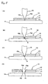
Fig. 1(A) to (D) are views schematically showing a cutting method of a multilayer structure according to the present invention. -
Fig. 2 are views schematically showing a multilayer container produced in accordance with a molding method of a multilayer container, in which (A) is a front view half in section, (B) is an enlarged sectional view of a flange end portion, (C) is an enlarged flange end portion having a clamp flaw. -
Fig. 3(A) is a sectional view showing a mold of the multilayer container ofFig. 2 ,Fig. 3(B) is a perspective view of a push cutter of the mold of 3(A), andFig. 3(C) is a perspective view showing the push cut in form of ring. -
Figs. 4(A) to (D) are views showing molding steps of the multilayer container. -
Figs. 5(A) to (D) are views showing molding steps of the multilayer container. -
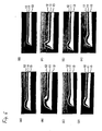
Fig. 6(A) to (H) are views showing examples of a photograph of a section of a flange portion molded by the forming method of the multilayer container of the present invention. - Hereunder, the present invention will be described with reference to embodiments shown in the drawings.
-
Fig. 1 is a schematic view explaining the cutting method of the multilayer (or multi-layered) structure according to the present invention. - A
multilayer structure 10 to be cut is composed of a sheet of three-layered structure including anintermediate resin layer 11 as an intermediate layer and a pair ofsurface resin layers intermediate resin layer 11 therebetween. Bonding agent layers, not shown, may be formed between theadjacent layers - In
such multilayer structure 10, at least one layer is in a fused state, and by pushing apush cutter 15 by a predetermined amount into themultilayer structure 10, which is supported at one side thereof by a cutter receiving (bearing)portion 14, from the other side thereof, therespective layers Fig. 1(A) and (B) ). Further, though not shown herein, the resin layer as the lower layer is bilaterally pushed byside surfaces push cutter 15 so as to be slightly creased as protruded portion expanding outward on both side portions of thepush cutter 15. The shape or size of the creasedprotruded portion 121a will change in accordance with the molding conditions, the thickness of the resin layer and the angle of the hand push cutter. - In the next step, a portion S compressed so as to provide the thin thickness portion is cut by pushing down the
push cutter 15 till the blade front edge thereof abuts against of thecutter receiving portion 14, and the respective layers of theintermediate resin layer 11 and thesurface resin layers push cutter 15 and the cutter receiving portion 14 (seeFig. 1(C) ). - Since the
push cutter 15 bites deeply at least one of the layers in the fused state, the fused layer is not cut off and deformed so as to provide inclined surfaces following the shapes of the side surfaces of thepush cutter 15, and theend face 10a of thecut multilayer structure 10 is maintained in a state covered with one of thesurface resin layer 12 without theintermediate resin layer 11 being exposed outside. - Furthermore, since the thin thickness portion S of the entire layer structure is finally cut off, the respective layers are pressed till the respective layers have crushed so as to provide very thin thickness portions and then cut, so that the cutting points A1 and A2 are converged substantially to one point. Especially, as to the
intermediate resin layer 11, the cut portion thereof has a very thin thickness and is substantially covered by the pairedsurface resin layers intermediate resin layer 11 therebetween. - The biting depth (dimension) of the
push cutter 15 in the fused state of the layer will be suitably selected in consideration of the thickness of themultilayer structure 10, the structure of the layers, the kinds of the resin materials and so on. - The push cutting of the thin thickness portion S is done after cooled and hardened below a melting point of temperature of the resin constituting each layer of the
multilayer structure 10,. - It is desirable that the
push cutter 15 has a normal temperature, and it is also desirable for thecutter receiving portion 14 to have a normal temperature. - The
push cutter 15 is composed of a flexible belt-shaped cutter blade. The belt-shaped cutter can cut the structure in linear form, curved form or endless circular form. - The
push cutter 15 has both inclined side surfaces 15a and 15b providing double edge shape. In a structure that both side surfaces form a small angle, thesurface resin layer 12 will be cut, and therefore, it will be desired for such angle to be more than 30 degrees. - The
push cutter 15 may have asymmetric double edge shape of the side surfaces 15a and 15b in its angle or have a single edge shape having only one inclined side surface. - That is, as shown in
Fig. 5(E) , thepush cutter 15 has oneside surface 15a, which is formed into flat shape, abutting against theend edge face 121 of the flange portion 20 of thecontainer 100, and on the other hand, theother side surface 15b is formed as inclined surface. In such structure, the protruding amount of the protrudedportion 121 a will be suppressed minimally, thus being desirable. -
Fig. 2 represents a multilayer (multi-layered)container 10 formed from the multilayer structure in form of sheet. - The
multilayer container 100 comprises a cup-shapedcontainer body 110 which is drawn from the sheet-shapedmultilayer structure 10 mentioned above and a flange orflanged portion 120 extending outward from a peripheral edge portion of an opening of the cup-shapedcontainer body 110, and thecontainer 100 is formed, using the multilayer structure cutting method mentioned above, by push-cutting a portion corresponding to the outer end of theflange portion 120 of themultilayer structure 10 between thepush cutter 15 and thecutter receiving portion 14 so as to provide a predetermined shape. - The thicknesses of the respective resin layers of the
multilayer structure 10, will be as follows: thesurface resin layer 13 as lowermost layer (constituting an outer layer of the container wall) has a largest thickness corresponding to substantially half thickness of the container wall, thesurface resin layer 12 as uppermost layer (constituting an inner layer of the container wall) has a smallest thickness, and theintermediate resin layer 11 has a middle thickness therebetween. - The
flange portion 120 has, as shown inFig. 2(B) , alower surface portion 123 and anupper surface portion 124 both being in parallel to each other, the former having a diameter larger than the latter, and theflange end face 121 is formed as an inclining surface portion widened downward from the outer diameter end portion of the flangeupper surface portion 124 towards the outer diameter end portion of the flangelower surface portion 123. - The
flange end face 121 has a sharp-angled lower edge portion as a cutting (or cut)point 122 of thepush cutter 15, and the respective layers forming theflange portion 120 are converged, at their end portions, to thiscutting point 122. - The respective resin layers 11, 12 and 13 constituting the
flange portion 120 are parallel to the flangelower surface 123 and the flangeupper surface 124 and have a structure converged to thecut point 122 at the ends of theflange portion 12. Further, portions between these parallel portions and converged portions are creased as protruded portion, on theupper surface 124 side by laterally pressed by the side surfaces of thepush cutter 15. - That is, the sectional converged shape of the
end portion 13a of thesurface resin layer 13 as the lowermost layer has a triangle shape having thecutting point 122 being the apex point, and an angle constituted by a boundary surface m1 between theintermediate resin layer 11 and the flangelower surface 123 with respect thereto is smaller than the angle constituted by theflange end face 121 with respect to thelower surface portion 123. - The
end portion 11a of theintermediate resin layer 11 has a rostral shape in section with thecutting point 122 being the apex point, which is overlapped with theend portion 13a of the lowersurface resin layer 13 in shape of triangle. - The
end portion 12a of the uppersurface resin layer 12 has a thin thickness, extends to thecutting point 122 and is overlapped with the lower rostral-shapedend portion 11 a of theintermediate resin layer 11. - The lower
surface resin layer 13 has a creased (protruded)portion 13b which is protruded towards theintermediate resin layer 11 side at the boundary surface ml between theintermediate resin layer 11 and thesurface resin layer 13, and the creased (protruded)portion 11b of theintermediate resin layer 11 and the creasedportion 12b of the uppersurface resin layer 12 are overlapped, in location, with the creasedportion 13b of the lowersurface resin layer 13. - The
end portion 12a of the uppersurface resin layer 12 has a thin thickness and is totally expanded, so that theend portion 12a has less change in thickness compared with the lower resin layer, at which the end portion thereof extends finely towards the front end thereof. On the other hand, theend portion 13a of the lowermostsurface resin layer 13 does not extend downward and is deformed laterally under compression by the pushing force of thepush cutter 15 to thereby make large the creasedportion 13b. The deformation of theintermediate resin layer 11 is middle. Thus, the deformed conditions of the respective layers change depending on the thicknesses of the respective resin layers, the positional relationship therebetween and the like. -
Fig. 2(C) shows an example having aclamp mark 125 at a time when theflange portion 120 is pressed by the mold at the molding process. Since theflange portion 120 is compressed by the clamping pressure, thecreased portions - The surface resin layers 12 and 13 of the
multilayer structure 10 forming themultilayer container 100 is formed of a thermoplastic resin such as polypropylene group resin, and theintermediate resin layer 11 is formed from a single layer structure of the oxygen absorbing layer or gas shut-off layer or double layer structure of these layers. - As the oxygen absorbing layer, a thermoplastic resin mixed with an iron series deoxidizing agent or other oxygen absorbing polymers (olefin type, polyester type, urethane type or like).
- The oxygen absorbing polymers include, for example, ethylene-vinyl acetate copolymer saponification compound and others which are prepared by blending polyamide group gas-barrier resins such as nylon 6, nylon 6• 6, nylon 6/6• 6 copolymer, metaxylylene adipamide with oxidizing resins or transition metal group catalyst.
- The oxidizing resins may include: (1) a resin including carbon side chain and at least one functional group, as main chain or side chain, selected from the groups of carboxylic acid group, carboxylic acid anhydride group, carboxylic acid ester group, carboxylic amide group, and carbonyl group, (2) a polyamide resin such as metaxylylene adipamide, (3) an ethylene group unsaturated group contained copolymer.
- The transition metal group catalyst is a catalyst for an oxidizing reaction of the oxidizing resin and is formed of organic acid salt or organic complex salt of the transition metal. The transition metal group catalysts include, for example, iron, cobalt, nickel, copper, silver, tin, titanium, zirconium, vanadium, chromium, manganese and so on.
- The gas shut-off layer is formed, for example, of ethylene-vinyl acetate copolymer saponification compound and others including blending polyamide group such as nylon 6, nylon 6• 6, nylon 6/6• 6 copolymer, metaxylylene adipamide, resin coating agent, inorganic evaporation layer and so on.
- The surface resin layers 12 and 13 are formed of thermoplastic resins including polypropylene group resin, polystyrene group resin, polyethylene terephthalate group resin or like. These paired surface resin layers 12 and 13 may be formed of resin materials different from each other.
- The
intermediate resin layer 11 may be formed from the single layer of oxygen absorbing layer, the single gas shut-off layer or other resin layer. Theintermediate layer 11 is not limited to the resin layer and may be formed of a metal layer such as aluminium foil layer. In the case of the multilayer structure including the intermediate layer composed of the metal layer such as aluminium foil layer, it will be preferably utilized for a film of a pouch. - Hereunder, with reference to
Figs. 3 to 5 , the method of forming the multilayer container of the structure mentioned above will be described. - The
multilayer container 100 is formed from the sheet-shapedmultilayer structure 10 into thecontainer body 110 having cubic structure by pneumatic forming (molding), vacuum forming (molding) or vacuum-pneumatic forming (molding), and at the same time of this container body forming, theflange portion 120 is punched out in the round form and cut off. - First, with reference to
Figs. 3 , the mold or molding die 200 will be described. - The mold or molding die 200 includes a pair of first and second mold halves 210 and 220 which clamps the
multilayer structure 10. Thepush cutter 15 is provided for thesecond mold half 220 and, on the other hand, asupport pedestal 212 constituting the cutter receiving portion is provided for thefirst mold half 210. - The
first mold half 210 has acavity 211 forming thecontainer body 110 and a flatannular support pedestal 212 provided for the peripheral edge portion of the opening of thecavity 211. Thesecond mold half 220 is provided with aclamp 221 engageable with an area of the upper surface of thesupport pedestal 212 of thefirst mold half 210 on the inner diameter side thereof. - A
plug 230 for pushing themultilayer structure 10 having at least one fused layer into thecavity 211 is provided on the side thesecond mold half 220. In the illustrated example, although theplug 230 is described to be movable with thesecond mold half 220, it may be disposed independently from thesecond mold half 220 so as to be movable separately. - Furthermore, an
ejector mold 240 for releasing themultilayer container 100 molded in thecavity 211 so as to be creased and protruded therein after the molding is provided for the bottom portion of thecavity 211 of thefirst mold half 210. - In addition, the
push cutter 15 for cutting under pressure theflange portion 120 is provided on the side of thesecond mold half 220. Thispush cutter 15 is arranged at a position opposing to the upper surface of thesupport pedestal 212 of thefirst mold half 210 on the outside of the outer end portion of theclamp portion 221 of thesecond mold half 220. The estimated cutting position by the front end portion of thepush cutter 15 is a position apart outside, by a predetermined distance, from the outer end of the clamp area of theclamp portion 221. - It is desirable to form the surface layer of the
support pedestal 212 with a hard material having heat insulation property, and asoft material 213 such as bronze is embedded, as a lower layer, below this hard surface layer so as to be capable of absorbing a shock at the abutment of thepush cutter 15. - The
push cutter 15 is formed from a flexible band-shaped cutter blade and used by connecting both ends thereof to be endlessly (seeFigs. 3(B) and (C) , and thepush cutter 15 is fitted to the inner periphery of aholder 250 and held thereby along the inner periphery thereof. Further, although, in the illustrated example, thepush cutter 15, i.e., theholder 250 has a circular shape, it may have a rectangular shape, elliptical shape or other shape in accordance with the shape of thecontainer 100. - Hereunder, the multilayer container forming (molding) method will be explained with reference to
Figs. 4 and5 . - The molding process includes a sheet feed step, preceding plug insertion step, a mold closing step, an pressure molding step, a flange portion cutting step and a knock out step.
- In the sheet feed step, as shown in
Fig. 4(A) , themultilayer structure 10 which has at least one of the layers in the fused state is fed to the upper surface of thefirst mold half 210 of the mold. Themultilayer structure 10 is weighed down by its self-weight into thecavity 211 of thefirst mold half 210. - In the preceding plug insertion step, as shown in
Fig. 4(B) , theplug 230 is pushed downward beforehand the molding of thecontainer body 110 so as to push themultilayer structure 10 into thecavity 211 of thefirst mold half 210 by a predetermined amount. - In the mold closing step, as shown in
Fig. 4(C) , thepush cutter 15 is pushed into themultilayer structure 10 by a predetermined depth during at least one layer of themultilayer structure 10 being maintained in the fused state beforehand the molding of thecontainer body 110. When thesecond mold half 220 contacts themultilayer structure 220, the temperature of themultilayer structure 10 is rapidly lowered and then hardened, so that, in the state of thesecond mold half 220 not contacting themultilayer structure 10, that is, in the state that the temperature of themultilayer structure 10 is kept to be more than its melting point, thepush cutter 15 is pushed into themultilayer structure 10 from its other side surface and themultilayer structure 10 is compressed into thin shape while deforming the respective layers so that the portions to be cut by thepush cutter 15 follow the sectional shape thereof. At this moment, the multilayer structure is not cut off and the front end of thepush cutter 15 and the upper surface of thesupport pedestal 212 are separated from each other by a distance corresponding to the thin thickness portion S. - Since at least one of the layers of the
multilayer structure 10 is in the fused state, theintermediate resin layer 11 and the paired surface resin layers 12 and 13 are not cut off and the respective layers are extended with thin thickness while maintaining the three-layer structure. - Further, since the above-mentioned preceding plug insertion step and the mold closing step shown in
Fig. 4(A) to (C) progress extremely rapidly in a short time, the fused state of at least one layer of the multilayer structure can be maintained. - Immediately after the biting of the
push cutter 15 into themultilayer structure 10 by the predetermined amount, the lower surface of thesecond mold half 220 contacts the upper surface of themultilayer structure 10 and the portion thereof inside the biting portion of thepush cutter 15 is clamped. - As shown in
Fig. 4(D) , themultilayer structure 10 is compressed by the clamping force through the lower surface of thesecond mold half 220, and an annularnon-compressed area 17 exists between the lower surface of thesecond mold half 220 and the bitingportion 16 of thepush cutter 15. Accordingly, the fluidized resin material is moved to thenon-compressed side 17 from the compressedportion 18 compressed by thesecond mold half 220 and the bitingportion 16 of thepush cutter 15, and then, the respective layers of themultilayer structure 10 are curved so as to be protruded entirely at thenon-compressed portion 17. - It is desired for the
push cutter 15 to have the normal temperature. - In the pneumatic molding step, as shown in
Fig. 5(A) , the pressurized air is blown into a space between thesecond mold half 220 and themultilayer structure 10 at an instant of the completion of the clamping, and themultilayer structure 10 is closely contacted to the inner periphery of thecavity 211 of thefirst mold half 210 so as to cool and harden the multilayer structure. Thecontainer body 110 may be formed by vacuuming the space between thefirst mold half 210 and themultilayer structure 10 in place of blowing the pressurized air. Further, thecontainer body 110 may be formed by both the pneumatic forming and vacuum forming. - In the flange portion push-cutting step, as shown in
Fig. 5(B) , after the formation of thecontainer body 110, thefirst mold half 210 is raised upward with thepush cutter 15 being stopped, and finally, the front end of thepush cutter 15 abuts against thesupport pedestal 212 to thereby push-cut the thin thickness portion S and form theflange portion 120. The cutting may be done by pushing down thepush cutter 15 with thefirst mold half 210 being fixed. - As this result, as shown in
Fig. 5(D) , theintermediate resin layer 11 and the surface resin layers 12, 13 are converged to the abutting portion A of thepush cutter 15 and thesupport pedestal 212. - Further, this push-cutting of the
flange portion 120 from themultilayer structure 10 may be performed in the fused state before the forming of the container body 110 (i.e., mold closing time). - After the push-cutting step, the product is knocked out.
- In this knock-out step, as shown in
Fig. 5(C) , with thefirst mold half 210 being fixed, thesecond mold half 220 and thepush cutter 15 are raised upward, and at the same time, the knock-outmold 240, arranged at the bottom portion, is pushed upward. Thus, the bottom portion of thecontainer body 110 is pushed upward, so that thecontainer body 110 is released from thecavity 211 of thefirst mold half 210. - Further, in the embodiment described above, although the
push cutter 15 is provided in adjacent to thesecond mold half 220 and thesupport pedestal 212 of thefirst mold half 210 is formed as the cutter receiving portion, the cutter receiving portion may be provided on the side of thesecond mold half 220 and thepush cutter 15 may be disposed in adjacent to thefirst mold half 210 having thecavity 211. - In addition, although the multilayer container formed, as a multilayer product, by cutting the periphery of a container such as cubic cup or tray, for example, the multilayer product may be a pouch constituting a bag formed of such multilayer structure.
-
Figs. 6(A) to (H) show photographs, in section, of the flange portions of the actually manufactured multilayer containers. - In any case of the photograph, the flange end portions of the respective resin layers 11, 12 and 13 are converged to the cut-off point, and therefore, the end faces of the flange portions can be completely covered by one of the resin layers without the intermediate resin layer being exposed to the flange end faces.
- Furthermore, as to the clamp flaw, as shown in
Figs. 6(C) and (E) , it does not appear in accordance with the forming conditions. Further, any creased and protruded portion is not substantially formed in the example ofFig. 6(E) .
Claims (10)
- A method of cutting a multilayer structure (10) composed of a plurality of resin layers (11, 12, 13) so as to provide a predetermined shape, comprising the steps of:compressing and deforming a multilayer structure (10), while extending respective layers (11, 12, 13) of the multilayer structure (10) to provide a thin thickness portion (S), so that an upper layer is pushed into a lower layer by pushing a push cutter (15), by a predetermined amount, into the multilayer structure (10) supported by a cutter receiving portion (14),in a fused state of at least one of the resin layers (11, 12, 13) forming the multilayer structure (10); andpush-cutting the compressed thin thickness portion (S) till the push cutter (15) abuts against the cutter receiving portion (14) so as to converge an intermediate layer (11) and surface resin layers (12, 13) of the multilayer structure (10) to the abutting portion (A) of the push cutter (15) and the cutter receiving portion (14),
characterized in thatthe push-cutting step is performed after the resin material (11, 12, 13) constituting the multilayer structure (10) is cooled and hardened below a melting point thereof. - The method of cutting a multilayer structure (10) according to claim 1, wherein the push cutter (15) has a normal temperature.
- The method of cutting a multilayer structure (10) according to claim 1, wherein the push cutter (15) is a belt-shaped cutter having both ends connected together endlessly.
- The method of cutting a multilayer structure (10) according to claim 2 or 3, wherein the push cutter (15) has an angled edge shape having at least one side surface (15a, 15b) inclined.
- The method of cutting a multilayer structure (10) according to any one of claims 1 to 4, wherein the multilayer structure (10) is in form of a sheet.
- The method of cutting a multilayer structure (10) according to any one of claims 1 to 4, wherein the multilayer structure (10) is a cup or tray.
- The method of cutting a multilayer structure (10) according to any one of claims 1 to 4, wherein the multilayer structure (10) is a pouch.
- The method of cutting a multilayer structure (10) according to any one of claims 1 to 7, wherein the intermediate layer (11) includes at least a gas shut-off layer.
- The method of cutting a multilayer structure (10) according to any one of claims 1 to 7, wherein the intermediate layer (11) includes at least an oxygen absorbing layer including an iron series deoxidizing agent.
- The method of cutting a multilayer structure (10) according to any one of claims 1 to 7, wherein the intermediate layer includes a two-layer structure composed of an oxygen absorbing layer and a gas shut-off layer.
Applications Claiming Priority (3)
| Application Number | Priority Date | Filing Date | Title |
|---|---|---|---|
| JP2002217342A JP4503220B2 (en) | 2002-07-25 | 2002-07-25 | Multilayer cutting method and multilayer molded article |
| JP2002217342 | 2002-07-25 | ||
| PCT/JP2003/009487 WO2004011211A1 (en) | 2002-07-25 | 2003-07-25 | Method of cutting multilayer body, method of forming multilayer container, and multilayer formed product |
Publications (4)
| Publication Number | Publication Date |
|---|---|
| EP1541303A1 EP1541303A1 (en) | 2005-06-15 |
| EP1541303A4 EP1541303A4 (en) | 2010-03-17 |
| EP1541303B1 true EP1541303B1 (en) | 2011-11-02 |
| EP1541303B8 EP1541303B8 (en) | 2012-02-29 |
Family
ID=31184652
Family Applications (1)
| Application Number | Title | Priority Date | Filing Date |
|---|---|---|---|
| EP20030771360 Expired - Lifetime EP1541303B8 (en) | 2002-07-25 | 2003-07-25 | Method of cutting multilayer body |
Country Status (9)
| Country | Link |
|---|---|
| US (2) | US7833379B2 (en) |
| EP (1) | EP1541303B8 (en) |
| JP (1) | JP4503220B2 (en) |
| KR (1) | KR20050037462A (en) |
| CN (1) | CN100357074C (en) |
| AT (1) | ATE531496T1 (en) |
| AU (1) | AU2003248129A1 (en) |
| DK (1) | DK1541303T3 (en) |
| WO (1) | WO2004011211A1 (en) |
Families Citing this family (19)
| Publication number | Priority date | Publication date | Assignee | Title |
|---|---|---|---|---|
| JP2008080387A (en) * | 2006-09-28 | 2008-04-10 | Toyota Motor Corp | R drilling method and R drilling device |
| JP4578458B2 (en) * | 2006-11-08 | 2010-11-10 | 有限会社紀和金属 | Ultrasonic welding equipment |
| JP5056517B2 (en) * | 2008-03-19 | 2012-10-24 | セイコーエプソン株式会社 | Nozzle plate manufacturing method and liquid jet head |
| JP5794518B2 (en) * | 2008-07-30 | 2015-10-14 | 株式会社▲高▼橋型精 | Punching mold |
| CA2835194A1 (en) * | 2011-05-05 | 2012-11-08 | Daktari Diagnostics, Inc. | Conductive patterns and methods for making conductive patterns |
| CN102514183A (en) * | 2011-12-28 | 2012-06-27 | 青岛海尔模具有限公司 | Hot press molding and cutting integrated mold for membrane |
| EP2727855A1 (en) * | 2012-06-04 | 2014-05-07 | Magic Pack S.R.L. | Food tray and method for obtaining the same |
| ITMI20120962A1 (en) * | 2012-06-04 | 2013-12-05 | Magic Pack S R L | MOLD FOR TRAY FOR FOOD AND TRAY SO IT IS OBTAINED |
| ITMI20120963A1 (en) * | 2012-06-04 | 2013-12-05 | Magic Pack S R L | FOOD TRAY AND PROCEDURE FOR ITS ACHIEVEMENT |
| DE112014003222T5 (en) * | 2013-07-09 | 2016-04-28 | Brita Gmbh | Method and plant for producing a fluid treatment element |
| JP6470007B2 (en) * | 2014-10-16 | 2019-02-13 | Toyo Tire株式会社 | Manufacturing method of rubber sheet with cord |
| US20180009125A1 (en) * | 2015-01-26 | 2018-01-11 | Riken Technos Corporation | Process for producing resinous panel |
| CH711043A1 (en) * | 2015-05-06 | 2016-11-15 | Berhalter Ag | Device for the punching of thin-walled materials. |
| KR102468967B1 (en) * | 2015-06-01 | 2022-11-22 | 쇼와 덴코 패키징 가부시키가이샤 | Container and packaging body |
| JP6738625B2 (en) * | 2015-06-01 | 2020-08-12 | 昭和電工パッケージング株式会社 | Containers and packages |
| DE102016201433A1 (en) | 2016-02-01 | 2017-08-03 | Bayerische Motoren Werke Aktiengesellschaft | Method for processing and / or producing a component |
| JP7396789B2 (en) * | 2018-08-10 | 2023-12-12 | 日東電工株式会社 | Wired circuit board, its manufacturing method, and wired circuit board assembly sheet |
| US20220219216A1 (en) * | 2021-01-14 | 2022-07-14 | Frontier Co., Ltd. | Stamping apparatus, method of stamping and stamping mold |
| SE547296C2 (en) * | 2022-04-08 | 2025-06-24 | Pulpac AB | A dry-forming mould system and a method for manufacturing a cellulose product in a dry-forming mould system |
Family Cites Families (35)
| Publication number | Priority date | Publication date | Assignee | Title |
|---|---|---|---|---|
| US2735797A (en) * | 1956-02-21 | Method of heat sealing and severing | ||
| US2635672A (en) * | 1950-11-29 | 1953-04-21 | Jr Herbert Rumsey | Apparatus for heat sealing and severing thermoplastic materials |
| BE628244A (en) * | 1962-02-12 | |||
| US3513052A (en) * | 1967-04-12 | 1970-05-19 | Fuji Photo Film Co Ltd | Method of forming a film package |
| US3574039A (en) * | 1967-11-02 | 1971-04-06 | Campbell Taggart Ass Bakeries | Film sealing and cutting apparatus |
| US3522135A (en) * | 1968-04-29 | 1970-07-28 | Fmc Corp | Rotating heat sealing head with cooling means |
| US4053671A (en) * | 1973-01-24 | 1977-10-11 | Carlisle Richard S | Article having edge-sealed films |
| US4069727A (en) * | 1974-11-27 | 1978-01-24 | Rospatch Corporation | Separation of label tape into labels |
| US4648931A (en) * | 1983-12-15 | 1987-03-10 | Johnston Orin B | Method of forming bead seal in biaxially oriented polymer film by heat bonding |
| US4708760A (en) * | 1985-11-04 | 1987-11-24 | Chrysler Motors Corporation | Cutting and heat sealing apparatus for vehicle seat inserts |
| JPS62170324A (en) * | 1986-01-23 | 1987-07-27 | Toyota Motor Corp | Laminate cutting treatment and high frequency welding method |
| JPS63150200A (en) * | 1986-12-16 | 1988-06-22 | 出光石油化学株式会社 | Annular notch forming device to vessel flange section |
| EP0370798B1 (en) * | 1988-11-22 | 1994-10-26 | Mitsui Petrochemical Industries, Ltd. | Heat-bonding blade and heat-bonding apparatus |
| CN1011766B (en) * | 1989-07-15 | 1991-02-27 | 太原重型机器厂 | Shearing and crushing of titanium sponge and special equipment thereof |
| JPH0825159B2 (en) * | 1989-11-18 | 1996-03-13 | 高島屋日発工業株式会社 | Cutting method and cutting device for laminated skin material having pad layer |
| JP3117732B2 (en) * | 1990-12-21 | 2000-12-18 | 株式会社ブリヂストン | Method and apparatus for cutting and forming a band-shaped member |
| JPH04360794A (en) * | 1991-06-07 | 1992-12-14 | Sekisui Chem Co Ltd | Resin made sheet body continuous punching method and punching device therefor |
| JPH04136698U (en) * | 1991-06-12 | 1992-12-18 | 一幸 水野 | sheet punching equipment |
| JPH0550499A (en) | 1991-08-27 | 1993-03-02 | Kuwabara Yasunaga | Trimming method in mold and container |
| EP0540495A1 (en) * | 1991-10-30 | 1993-05-05 | GFM Gesellschaft für Fertigungstechnik und Maschinenbau Aktiengesellschaft | Method of cutting workpieces made from fibre reinforced plastic |
| DE4208565A1 (en) * | 1991-11-29 | 1993-09-23 | Roeder & Spengler Stanz | PUNCHING KNIFE |
| JPH07227259A (en) | 1994-02-14 | 1995-08-29 | Sumitomo Chem Co Ltd | Multi-layer sheet molding |
| US6066226A (en) * | 1994-08-03 | 2000-05-23 | Mitsubishi Gas Chemical Company, Inc. | Method of making a sheet-shaped oxygen absorber |
| JPH08112880A (en) * | 1994-08-22 | 1996-05-07 | Dainippon Printing Co Ltd | Laminated body and lid and bag body using the same |
| JP3413539B2 (en) * | 1995-03-08 | 2003-06-03 | 四国化工機株式会社 | Liquid sealing tube heat sealing device |
| US5667864A (en) * | 1995-06-07 | 1997-09-16 | Landoll; Leo M. | Absorbant laminates and method of making same |
| JPH1015879A (en) | 1996-07-02 | 1998-01-20 | Konica Corp | Cutting blade and cutting method |
| US5766400A (en) * | 1996-08-27 | 1998-06-16 | Liteliner, L.L.C. | Method of producing prefabricated multi layered flexible products and products having improved sealing profiles resulting therefrom |
| JPH1071595A (en) * | 1996-08-27 | 1998-03-17 | Matsushita Electric Works Ltd | Cutting method for prepreg and cutting device for prepreg using the method |
| US6036811A (en) * | 1996-08-27 | 2000-03-14 | Liteliner International Holdings, Co., Llc | Leakproof seams for non-containable waterproof/breathable fabric composites |
| DE19725949C2 (en) | 1997-06-19 | 1999-09-02 | Silver Plastics Gmbh & Co Kg | Packaging tray for food and a method for producing these packaging trays |
| US6367361B1 (en) * | 1997-07-30 | 2002-04-09 | Ford Motor Company | Method and apparatus for trimming thermoformed films |
| JP4120712B2 (en) | 1997-08-06 | 2008-07-16 | 三菱瓦斯化学株式会社 | Deoxidizing multilayer container |
| US6224792B1 (en) * | 1999-04-13 | 2001-05-01 | 3M Innovative Properties Company | Cutting and edge sealing cellular retroreflective sheeting |
| JP2001328099A (en) * | 2000-05-22 | 2001-11-27 | Kasai Kogyo Co Ltd | End processing method for surface material and end structure |
-
2002
- 2002-07-25 JP JP2002217342A patent/JP4503220B2/en not_active Expired - Lifetime
-
2003
- 2003-07-25 AT AT03771360T patent/ATE531496T1/en active
- 2003-07-25 WO PCT/JP2003/009487 patent/WO2004011211A1/en not_active Ceased
- 2003-07-25 DK DK03771360T patent/DK1541303T3/en active
- 2003-07-25 EP EP20030771360 patent/EP1541303B8/en not_active Expired - Lifetime
- 2003-07-25 KR KR1020057001260A patent/KR20050037462A/en not_active Ceased
- 2003-07-25 CN CNB038172291A patent/CN100357074C/en not_active Expired - Lifetime
- 2003-07-25 AU AU2003248129A patent/AU2003248129A1/en not_active Abandoned
- 2003-07-25 US US10/522,392 patent/US7833379B2/en active Active
-
2009
- 2009-08-14 US US12/541,294 patent/US7942996B2/en not_active Expired - Lifetime
Also Published As
| Publication number | Publication date |
|---|---|
| CN100357074C (en) | 2007-12-26 |
| US7833379B2 (en) | 2010-11-16 |
| EP1541303A4 (en) | 2010-03-17 |
| EP1541303A1 (en) | 2005-06-15 |
| CN1668429A (en) | 2005-09-14 |
| AU2003248129A1 (en) | 2004-02-16 |
| US20060185789A1 (en) | 2006-08-24 |
| AU2003248129A8 (en) | 2004-02-16 |
| US7942996B2 (en) | 2011-05-17 |
| JP2004058181A (en) | 2004-02-26 |
| WO2004011211A1 (en) | 2004-02-05 |
| KR20050037462A (en) | 2005-04-21 |
| ATE531496T1 (en) | 2011-11-15 |
| JP4503220B2 (en) | 2010-07-14 |
| US20090304960A1 (en) | 2009-12-10 |
| DK1541303T3 (en) | 2012-01-30 |
| EP1541303B8 (en) | 2012-02-29 |
Similar Documents
| Publication | Publication Date | Title |
|---|---|---|
| US7942996B2 (en) | Method of cutting multilayer body, method of forming multilayer container, and multilayer formed product | |
| US8137493B2 (en) | Multi-component product container with reclosable top | |
| EP0140282B1 (en) | Can-like container and method for manufacturing same | |
| CN106414251B (en) | Laminated peel container and method for producing the same | |
| WO2004017375A2 (en) | Multi-component packaging system and method for manufacture | |
| JP2004307024A (en) | Container, package, and method of manufacturing container | |
| JP5931340B2 (en) | Packaging container, packaging container manufacturing method and manufacturing apparatus | |
| JPH06219435A (en) | Formation of container of polymer and transmission preventing container | |
| KR101790808B1 (en) | Easy-open container and production method thereof | |
| CN115190859A (en) | Packaging, process and equipment for making said packaging | |
| JP4717656B2 (en) | Easy-open container, container body, easy-open container manufacturing method, and easy-open container manufacturing apparatus | |
| JP5011321B2 (en) | Method for forming multilayer container | |
| JP4599966B2 (en) | Flange molding method for flanged container, flanged container, and easy-open container | |
| JP3937301B2 (en) | Multilayer cut method and multilayer cut product | |
| JP4876679B2 (en) | Packaging container for microwave oven and manufacturing method thereof | |
| JP2001301063A (en) | Method and apparatus for producing specially shaped pouch | |
| JP6122274B2 (en) | SEALING MACHINE, SEALING METHOD, SEALING DEVICE, AND CONTAINER MANUFACTURING METHOD | |
| KR102230835B1 (en) | Notching blade, machining device, notch-forming device, notch-forming method, and container | |
| JP2006298410A (en) | Degassing valve label, and its manufacturing method | |
| JP5965817B2 (en) | Container, packaging container, container manufacturing method, and packaging container manufacturing method | |
| JP2014198575A (en) | Container body, container, molding method, and molding machine | |
| JP2013159368A (en) | Cap for soft plastic container, soft plastic container, and method for manufacturing the same | |
| JPH07700U (en) | Annular notch forming device for container flange | |
| JPH04308722A (en) | Manufacturing method for kagami-mochi containers |
Legal Events
| Date | Code | Title | Description |
|---|---|---|---|
| PUAI | Public reference made under article 153(3) epc to a published international application that has entered the european phase |
Free format text: ORIGINAL CODE: 0009012 |
|
| 17P | Request for examination filed |
Effective date: 20050125 |
|
| AK | Designated contracting states |
Kind code of ref document: A1 Designated state(s): AT BE BG CH CY CZ DE DK EE ES FI FR GB GR HU IE IT LI LU MC NL PT RO SE SI SK TR |
|
| AX | Request for extension of the european patent |
Extension state: AL LT LV MK |
|
| DAX | Request for extension of the european patent (deleted) | ||
| A4 | Supplementary search report drawn up and despatched |
Effective date: 20100211 |
|
| RIC1 | Information provided on ipc code assigned before grant |
Ipc: B32B 7/02 20060101ALI20100205BHEP Ipc: B65D 81/38 20060101ALI20100205BHEP Ipc: B32B 27/18 20060101ALI20100205BHEP Ipc: B26F 1/40 20060101AFI20040219BHEP Ipc: B65D 1/28 20060101ALI20100205BHEP Ipc: B32B 1/04 20060101ALI20100205BHEP Ipc: B65D 1/34 20060101ALI20100205BHEP Ipc: B65D 81/26 20060101ALI20100205BHEP Ipc: B65D 1/26 20060101ALI20100205BHEP |
|
| 17Q | First examination report despatched |
Effective date: 20100712 |
|
| RAP1 | Party data changed (applicant data changed or rights of an application transferred) |
Owner name: TOYO SEIKAN KAISHA, LTD. |
|
| GRAP | Despatch of communication of intention to grant a patent |
Free format text: ORIGINAL CODE: EPIDOSNIGR1 |
|
| RIC1 | Information provided on ipc code assigned before grant |
Ipc: B65D 1/34 20060101ALI20110524BHEP Ipc: B32B 7/02 20060101ALI20110524BHEP Ipc: B65D 1/28 20060101ALI20110524BHEP Ipc: B32B 1/04 20060101ALI20110524BHEP Ipc: B65D 81/38 20060101ALI20110524BHEP Ipc: B65D 1/26 20060101ALI20110524BHEP Ipc: B65D 81/26 20060101ALI20110524BHEP Ipc: B32B 27/18 20060101ALI20110524BHEP Ipc: B26F 1/40 20060101AFI20110524BHEP |
|
| RTI1 | Title (correction) |
Free format text: METHOD OF CUTTING MULTILAYER BODY |
|
| GRAS | Grant fee paid |
Free format text: ORIGINAL CODE: EPIDOSNIGR3 |
|
| GRAA | (expected) grant |
Free format text: ORIGINAL CODE: 0009210 |
|
| AK | Designated contracting states |
Kind code of ref document: B1 Designated state(s): AT BE BG CH CY CZ DE DK EE ES FI FR GB GR HU IE IT LI LU MC NL PT RO SE SI SK TR |
|
| REG | Reference to a national code |
Ref country code: GB Ref legal event code: FG4D |
|
| REG | Reference to a national code |
Ref country code: CH Ref legal event code: EP |
|
| REG | Reference to a national code |
Ref country code: IE Ref legal event code: FG4D |
|
| RIN2 | Information on inventor provided after grant (corrected) |
Inventor name: MIZOGUCHI, KENICHI Inventor name: MATSUMURA, YASUYO Inventor name: TAKAI, TOSHIHIRO Inventor name: HARUTA, TOMOAKI Inventor name: USAMI, HIDEKI Inventor name: TANAKA, SHINJI Inventor name: MATSUOKA, KIKUO |
|
| REG | Reference to a national code |
Ref country code: DE Ref legal event code: R096 Ref document number: 60338994 Country of ref document: DE Effective date: 20120112 |
|
| REG | Reference to a national code |
Ref country code: DK Ref legal event code: T3 |
|
| REG | Reference to a national code |
Ref country code: NL Ref legal event code: VDEP Effective date: 20111102 |
|
| PG25 | Lapsed in a contracting state [announced via postgrant information from national office to epo] |
Ref country code: SI Free format text: LAPSE BECAUSE OF FAILURE TO SUBMIT A TRANSLATION OF THE DESCRIPTION OR TO PAY THE FEE WITHIN THE PRESCRIBED TIME-LIMIT Effective date: 20111102 Ref country code: NL Free format text: LAPSE BECAUSE OF FAILURE TO SUBMIT A TRANSLATION OF THE DESCRIPTION OR TO PAY THE FEE WITHIN THE PRESCRIBED TIME-LIMIT Effective date: 20111102 Ref country code: SE Free format text: LAPSE BECAUSE OF FAILURE TO SUBMIT A TRANSLATION OF THE DESCRIPTION OR TO PAY THE FEE WITHIN THE PRESCRIBED TIME-LIMIT Effective date: 20111102 Ref country code: BE Free format text: LAPSE BECAUSE OF FAILURE TO SUBMIT A TRANSLATION OF THE DESCRIPTION OR TO PAY THE FEE WITHIN THE PRESCRIBED TIME-LIMIT Effective date: 20111102 Ref country code: PT Free format text: LAPSE BECAUSE OF FAILURE TO SUBMIT A TRANSLATION OF THE DESCRIPTION OR TO PAY THE FEE WITHIN THE PRESCRIBED TIME-LIMIT Effective date: 20120302 Ref country code: GR Free format text: LAPSE BECAUSE OF FAILURE TO SUBMIT A TRANSLATION OF THE DESCRIPTION OR TO PAY THE FEE WITHIN THE PRESCRIBED TIME-LIMIT Effective date: 20120203 |
|
| PG25 | Lapsed in a contracting state [announced via postgrant information from national office to epo] |
Ref country code: CY Free format text: LAPSE BECAUSE OF FAILURE TO SUBMIT A TRANSLATION OF THE DESCRIPTION OR TO PAY THE FEE WITHIN THE PRESCRIBED TIME-LIMIT Effective date: 20111102 |
|
| PG25 | Lapsed in a contracting state [announced via postgrant information from national office to epo] |
Ref country code: BG Free format text: LAPSE BECAUSE OF FAILURE TO SUBMIT A TRANSLATION OF THE DESCRIPTION OR TO PAY THE FEE WITHIN THE PRESCRIBED TIME-LIMIT Effective date: 20120202 Ref country code: EE Free format text: LAPSE BECAUSE OF FAILURE TO SUBMIT A TRANSLATION OF THE DESCRIPTION OR TO PAY THE FEE WITHIN THE PRESCRIBED TIME-LIMIT Effective date: 20111102 Ref country code: CZ Free format text: LAPSE BECAUSE OF FAILURE TO SUBMIT A TRANSLATION OF THE DESCRIPTION OR TO PAY THE FEE WITHIN THE PRESCRIBED TIME-LIMIT Effective date: 20111102 Ref country code: SK Free format text: LAPSE BECAUSE OF FAILURE TO SUBMIT A TRANSLATION OF THE DESCRIPTION OR TO PAY THE FEE WITHIN THE PRESCRIBED TIME-LIMIT Effective date: 20111102 |
|
| PG25 | Lapsed in a contracting state [announced via postgrant information from national office to epo] |
Ref country code: IT Free format text: LAPSE BECAUSE OF FAILURE TO SUBMIT A TRANSLATION OF THE DESCRIPTION OR TO PAY THE FEE WITHIN THE PRESCRIBED TIME-LIMIT Effective date: 20111102 Ref country code: RO Free format text: LAPSE BECAUSE OF FAILURE TO SUBMIT A TRANSLATION OF THE DESCRIPTION OR TO PAY THE FEE WITHIN THE PRESCRIBED TIME-LIMIT Effective date: 20111102 |
|
| PLBE | No opposition filed within time limit |
Free format text: ORIGINAL CODE: 0009261 |
|
| STAA | Information on the status of an ep patent application or granted ep patent |
Free format text: STATUS: NO OPPOSITION FILED WITHIN TIME LIMIT |
|
| REG | Reference to a national code |
Ref country code: AT Ref legal event code: MK05 Ref document number: 531496 Country of ref document: AT Kind code of ref document: T Effective date: 20111102 |
|
| 26N | No opposition filed |
Effective date: 20120803 |
|
| REG | Reference to a national code |
Ref country code: DE Ref legal event code: R097 Ref document number: 60338994 Country of ref document: DE Effective date: 20120803 |
|
| PG25 | Lapsed in a contracting state [announced via postgrant information from national office to epo] |
Ref country code: AT Free format text: LAPSE BECAUSE OF FAILURE TO SUBMIT A TRANSLATION OF THE DESCRIPTION OR TO PAY THE FEE WITHIN THE PRESCRIBED TIME-LIMIT Effective date: 20111102 |
|
| PG25 | Lapsed in a contracting state [announced via postgrant information from national office to epo] |
Ref country code: MC Free format text: LAPSE BECAUSE OF NON-PAYMENT OF DUE FEES Effective date: 20120731 |
|
| REG | Reference to a national code |
Ref country code: CH Ref legal event code: PL |
|
| PG25 | Lapsed in a contracting state [announced via postgrant information from national office to epo] |
Ref country code: LI Free format text: LAPSE BECAUSE OF NON-PAYMENT OF DUE FEES Effective date: 20120731 Ref country code: ES Free format text: LAPSE BECAUSE OF FAILURE TO SUBMIT A TRANSLATION OF THE DESCRIPTION OR TO PAY THE FEE WITHIN THE PRESCRIBED TIME-LIMIT Effective date: 20120213 Ref country code: CH Free format text: LAPSE BECAUSE OF NON-PAYMENT OF DUE FEES Effective date: 20120731 |
|
| REG | Reference to a national code |
Ref country code: IE Ref legal event code: MM4A |
|
| PG25 | Lapsed in a contracting state [announced via postgrant information from national office to epo] |
Ref country code: FI Free format text: LAPSE BECAUSE OF FAILURE TO SUBMIT A TRANSLATION OF THE DESCRIPTION OR TO PAY THE FEE WITHIN THE PRESCRIBED TIME-LIMIT Effective date: 20111102 |
|
| PG25 | Lapsed in a contracting state [announced via postgrant information from national office to epo] |
Ref country code: IE Free format text: LAPSE BECAUSE OF NON-PAYMENT OF DUE FEES Effective date: 20120725 |
|
| PG25 | Lapsed in a contracting state [announced via postgrant information from national office to epo] |
Ref country code: TR Free format text: LAPSE BECAUSE OF FAILURE TO SUBMIT A TRANSLATION OF THE DESCRIPTION OR TO PAY THE FEE WITHIN THE PRESCRIBED TIME-LIMIT Effective date: 20111102 |
|
| PG25 | Lapsed in a contracting state [announced via postgrant information from national office to epo] |
Ref country code: LU Free format text: LAPSE BECAUSE OF NON-PAYMENT OF DUE FEES Effective date: 20120725 |
|
| PG25 | Lapsed in a contracting state [announced via postgrant information from national office to epo] |
Ref country code: HU Free format text: LAPSE BECAUSE OF FAILURE TO SUBMIT A TRANSLATION OF THE DESCRIPTION OR TO PAY THE FEE WITHIN THE PRESCRIBED TIME-LIMIT Effective date: 20030725 |
|
| REG | Reference to a national code |
Ref country code: FR Ref legal event code: PLFP Year of fee payment: 14 |
|
| REG | Reference to a national code |
Ref country code: FR Ref legal event code: PLFP Year of fee payment: 15 |
|
| REG | Reference to a national code |
Ref country code: FR Ref legal event code: PLFP Year of fee payment: 16 |
|
| PGFP | Annual fee paid to national office [announced via postgrant information from national office to epo] |
Ref country code: GB Payment date: 20220720 Year of fee payment: 20 Ref country code: DK Payment date: 20220725 Year of fee payment: 20 Ref country code: DE Payment date: 20220720 Year of fee payment: 20 |
|
| PGFP | Annual fee paid to national office [announced via postgrant information from national office to epo] |
Ref country code: FR Payment date: 20220720 Year of fee payment: 20 |
|
| REG | Reference to a national code |
Ref country code: DE Ref legal event code: R071 Ref document number: 60338994 Country of ref document: DE |
|
| REG | Reference to a national code |
Ref country code: DK Ref legal event code: EUP Expiry date: 20230725 |
|
| REG | Reference to a national code |
Ref country code: GB Ref legal event code: PE20 Expiry date: 20230724 |
|
| PG25 | Lapsed in a contracting state [announced via postgrant information from national office to epo] |
Ref country code: GB Free format text: LAPSE BECAUSE OF EXPIRATION OF PROTECTION Effective date: 20230724 |