EP1541269A1 - Circular saw - Google Patents
Circular saw Download PDFInfo
- Publication number
- EP1541269A1 EP1541269A1 EP20040028742 EP04028742A EP1541269A1 EP 1541269 A1 EP1541269 A1 EP 1541269A1 EP 20040028742 EP20040028742 EP 20040028742 EP 04028742 A EP04028742 A EP 04028742A EP 1541269 A1 EP1541269 A1 EP 1541269A1
- Authority
- EP
- European Patent Office
- Prior art keywords
- blade
- case
- cooling air
- dust
- dust case
- Prior art date
- Legal status (The legal status is an assumption and is not a legal conclusion. Google has not performed a legal analysis and makes no representation as to the accuracy of the status listed.)
- Granted
Links
- 239000000428 dust Substances 0.000 claims abstract description 116
- 238000001816 cooling Methods 0.000 claims abstract description 106
- 238000005520 cutting process Methods 0.000 claims description 25
- 229910052751 metal Inorganic materials 0.000 claims description 19
- 239000002184 metal Substances 0.000 claims description 19
- 238000004804 winding Methods 0.000 claims description 3
- 238000004891 communication Methods 0.000 description 8
- XEEYBQQBJWHFJM-UHFFFAOYSA-N Iron Chemical compound [Fe] XEEYBQQBJWHFJM-UHFFFAOYSA-N 0.000 description 6
- 230000002093 peripheral effect Effects 0.000 description 5
- 238000000034 method Methods 0.000 description 4
- 229910000831 Steel Inorganic materials 0.000 description 3
- 229910052742 iron Inorganic materials 0.000 description 3
- 239000010959 steel Substances 0.000 description 3
- 229910000838 Al alloy Inorganic materials 0.000 description 2
- 238000010276 construction Methods 0.000 description 2
- 239000003779 heat-resistant material Substances 0.000 description 2
- 239000000463 material Substances 0.000 description 2
- 239000000203 mixture Substances 0.000 description 2
- 239000004575 stone Substances 0.000 description 2
- 229920003051 synthetic elastomer Polymers 0.000 description 2
- 229920003002 synthetic resin Polymers 0.000 description 2
- 239000000057 synthetic resin Substances 0.000 description 2
- 239000005061 synthetic rubber Substances 0.000 description 2
- 239000002023 wood Substances 0.000 description 2
- 238000010438 heat treatment Methods 0.000 description 1
- 238000004519 manufacturing process Methods 0.000 description 1
- 235000012054 meals Nutrition 0.000 description 1
- 238000005192 partition Methods 0.000 description 1
Images


Classifications
-
- B—PERFORMING OPERATIONS; TRANSPORTING
- B23—MACHINE TOOLS; METAL-WORKING NOT OTHERWISE PROVIDED FOR
- B23Q—DETAILS, COMPONENTS, OR ACCESSORIES FOR MACHINE TOOLS, e.g. ARRANGEMENTS FOR COPYING OR CONTROLLING; MACHINE TOOLS IN GENERAL CHARACTERISED BY THE CONSTRUCTION OF PARTICULAR DETAILS OR COMPONENTS; COMBINATIONS OR ASSOCIATIONS OF METAL-WORKING MACHINES, NOT DIRECTED TO A PARTICULAR RESULT
- B23Q11/00—Accessories fitted to machine tools for keeping tools or parts of the machine in good working condition or for cooling work; Safety devices specially combined with or arranged in, or specially adapted for use in connection with, machine tools
- B23Q11/12—Arrangements for cooling or lubricating parts of the machine
- B23Q11/126—Arrangements for cooling or lubricating parts of the machine for cooling only
- B23Q11/127—Arrangements for cooling or lubricating parts of the machine for cooling only for cooling motors or spindles
-
- B—PERFORMING OPERATIONS; TRANSPORTING
- B23—MACHINE TOOLS; METAL-WORKING NOT OTHERWISE PROVIDED FOR
- B23D—PLANING; SLOTTING; SHEARING; BROACHING; SAWING; FILING; SCRAPING; LIKE OPERATIONS FOR WORKING METAL BY REMOVING MATERIAL, NOT OTHERWISE PROVIDED FOR
- B23D59/00—Accessories specially designed for sawing machines or sawing devices
- B23D59/006—Accessories specially designed for sawing machines or sawing devices for removing or collecting chips
-
- B—PERFORMING OPERATIONS; TRANSPORTING
- B23—MACHINE TOOLS; METAL-WORKING NOT OTHERWISE PROVIDED FOR
- B23Q—DETAILS, COMPONENTS, OR ACCESSORIES FOR MACHINE TOOLS, e.g. ARRANGEMENTS FOR COPYING OR CONTROLLING; MACHINE TOOLS IN GENERAL CHARACTERISED BY THE CONSTRUCTION OF PARTICULAR DETAILS OR COMPONENTS; COMBINATIONS OR ASSOCIATIONS OF METAL-WORKING MACHINES, NOT DIRECTED TO A PARTICULAR RESULT
- B23Q11/00—Accessories fitted to machine tools for keeping tools or parts of the machine in good working condition or for cooling work; Safety devices specially combined with or arranged in, or specially adapted for use in connection with, machine tools
- B23Q11/0042—Devices for removing chips
- B23Q11/005—Devices for removing chips by blowing
-
- Y—GENERAL TAGGING OF NEW TECHNOLOGICAL DEVELOPMENTS; GENERAL TAGGING OF CROSS-SECTIONAL TECHNOLOGIES SPANNING OVER SEVERAL SECTIONS OF THE IPC; TECHNICAL SUBJECTS COVERED BY FORMER USPC CROSS-REFERENCE ART COLLECTIONS [XRACs] AND DIGESTS
- Y10—TECHNICAL SUBJECTS COVERED BY FORMER USPC
- Y10T—TECHNICAL SUBJECTS COVERED BY FORMER US CLASSIFICATION
- Y10T83/00—Cutting
- Y10T83/202—With product handling means
- Y10T83/2066—By fluid current
- Y10T83/207—By suction means
Definitions
- the present invention relates to a circular saw and more particularly, to a dust collecting circular saw having a dust case in which chips generated during operation of cutting a workpiece can be collected.
- Japanese laid-open utility model publication No. 5-41702 discloses a dust collecting circular saw for cutting metal workpiece such as a steel or iron plate.
- the known circular saw includes a dust case to collect chips generated during the metal workpiece cutting operation.
- an outlet for cooling air is formed in the side surface of a blade case that covers a blade.
- the cooling air to cool the motor is led from a motor housing into the blade case via an outlet and blown out onto the upper inner circumferential surface of the blade case.
- the blade case heated by the metal cutting chips can be cooled.
- the cooling air is introduced into the dust case to cool the dust case.
- due to momentum of the cooling air introduced into the dust case collected chips within the dust case may possibly escape out of the dust case. In this connection, further improvement of rational structure in the dust collecting circular saw is desired.
- an object of the invention to provide a dust collecting circular saw in which cooling air to cool the motor can be further effectively utilized.
- a representative circular saw may include a blade, a motor, a cooling fan, a dust case, a dust case cover and an air space between the dust case cover and the dust case.
- the cooling air to cool the motor is designed to be introduced into the air space. Therefore, according to the invention, heat of the dust case caused by hot chips collected within the dust case can be prevented from being transferred from the dust case to the dust case cover by the air space into which the cooling air is introduced. Thus, the user of the circular saw can securely be escaped from contacting any circular saw members heated by the hot chips within the dust case.
- the representative dust collecting typed circular saw may include a blade that cuts a workpiece, a motor that drives the blade, a cooling fan that generates a cooling air to cool the motor, a dust case that collects chips generated during the cutting operation by the blade, a dust case cover that covers at least part of the outside surface of the dust case and air space formed between the dust case cover and the dust case, wherein the cooling air is introduced into the air space.
- the representative circular saw is preferably applied to cut metal workpiece such as a steel material and an iron plate, while it can also be applied to cut wood or stone. Typically, when cutting metal workpiece, hot metal chips may be generated during the cutting operation and such hot chips may heat the dust case when chips are collected into the dust case.
- the representative circular saw introduces the cooling air to cool the motor into the air space between the heated dust case and the dust case cover.
- the cooling air can actively cool the outside surface of the dust case, chips within the dust case do not escape to the outside because the cooling air is not introduced into the dust case.
- the dust collecting circular saw 101 is designed for cutting metal workpiece such as a steel material and an iron plate.
- the circular saw 101 includes a circular saw body 103, a base 105 and a dust case 107.
- the base 105 is connected to the body 103 and placed in use on a workpiece (not shown).
- the dust case 107 is removably attached to the body 103 and chips generated during the cutting operation are collected in the dust case 107.
- a motor housing 111 and a blade case 113 is connected together to define the circular saw body 103.
- the motor housing 111 houses a driving motor 121 and a cooling fan 131.
- the cooling fan 131 is mounted on a driving shaft 123 of the driving motor 121 and rotated together with the driving shaft 123 when the driving motor 121 is driven.
- the blade case 113 houses a blade 129.
- a safety cover 115 is retractably attached to the lower region of the blade case 113.
- the blade case 113 has a handgrip 117 and a circular gear housing 114.
- the handgrip 117 is formed on the rearward outer circumferential portion of the blade case 113.
- the gear housing 114 is integrally formed on the side of the blade case 113 and bulges toward the motor housing 111.
- the handgrip 117 has a trigger 117a operated to start and stop the driving motor 117.
- the side peripheral edge portion or the end surface of the gear housing 114 which bulges toward the motor housing 111 butts the open end surface of the motor housing 111 and is connected to the motor housing 111 by bolts (not shown).
- a driven gear 133 (not shown) and a spindle 125 (see FIG. 3) are disposed within the gear housing 114 in a position corresponding to the position of the end of the driving shaft 123 that extends toward the gear housing 114.
- the driven gear is mounted on one end of the spindle 125 and a blade 129 is mounted on the other end of the spindle 125.
- the spindle 125, the blade 129 and the driven gear can rotate together in one piece.
- a driving gear 123a is formed on the end of the driving shaft 123 and engages the driven gear.
- the safety cover 115 is mounted on the spindle 125 and can rotate with respect to the spindle 125 via a rotation sliding portion 115a.
- the safety cover 115 is normally protruded from the underside of the base 105 by a biasing device (not shown) including a spring and covers the lower edge portion of the blade 129 for cutting a metal workpiece.
- a biasing device not shown
- the safety cover 115 is pushed and retracted by the workpiece, so that the safety cover 115 exposes the lower edge portion of the blade 129 and is housed within the blade case 113.
- Chips are generated by cutting the metal workpiece with the blade 129 and fly out in the tangential direction of the blade 129. Specifically, as shown by the thin arrows in FIG. 3, the chips fly upward into the blade case 113 and move toward a chip outlet 113b along an inner circumferential surface 113a of the peripheral wall of the blade case 113 or its vicinity.
- the chip outlet 113b is formed in the upper portion of the side wall surface of the blade case 113 on the side of the dust case 107.
- the metal workpiece generates relatively hot metal chips when being cut by the blade 129.
- the metal chips fly out into the blade case 113 generally heat the blade case 113. Therefore, the blade case 113 is made of metal such as aluminum alloy in consideration of heat resistance, while the outer surface of the blade case 113 becomes hot due to such hot metal chips.
- the entire outside surface of the blade case 113 including the gear housing 114 i.e. the side wall surface on the side of the motor housing 111, the side wall surface on the side of the dust case 107 and the peripheral wall surface connecting the both side wall surfaces, is covered with a blade case cover 119 formed of heat-resistant material, such as synthetic resin or synthetic rubber.
- a blade case cover 119 formed of heat-resistant material, such as synthetic resin or synthetic rubber.
- an appropriate clearance is provided between the blade case 113 and the blade case cover 119 so that a double wall having so-called air space is formed.
- the blade case cover 119 is removably connected to the blade case 113 by fastening means such as screws.
- the dust case 107 is disposed on the opposite side of the motor housing 111 with respect to the blade case 113.
- the dust case 107 is removably attached by a fastening device (not shown) to the side wall surface of the blade case 113 which faces the dust case 107.
- the dust case 107 has a dust collecting inlet (not shown) formed in a position to face the chip outlet 113b of the blade case 113. Hot chips flow into a dust collecting chamber 107a via the dust collecting inlet.
- the dust case 107 is formed of metal such as aluminum alloy in consideration of heat resistance against the hot meal chips.
- the dust case 107 may be heated by the collected chips and its outside surface may become hot. In view of this fact, in order to prevent the user from directly contacting the outside surface of the dust case 107, the entire outside surface is covered with a dust case cover 141 formed of heat-resistant material such as synthetic resin or synthetic rubber.
- the dust case cover 141 is arranged at a predetermined distance from the outside surface of the dust case 107, so that air space 143 is formed between the dust case 107 and the dust case cover 141.
- the dust case cover 141 has a bowl-like shape similar to the contours of the dust case 107.
- the dust case cover 141 is removably connected to the dust case 107 by fastening device such as screws, with the open peripheral edge portion of the dust case cover 141 in contact with the outside surface of the dust case 107 or the blade case cover 119.
- the cooling fan 131 on the driving shaft 123 of the driving motor 121 draws outside air into the motor housing 111 through an air intake (not shown) formed in a portion (the axial end) of the motor housing 111.
- the intake air flows within the motor housing 111, thereby cooling the driving motor 121.
- the air flows out into the gear housing 114 through the cooling fan 131.
- a generally annular cooling air outflow passage 145 is formed in the side surface of the gear housing 114 which faces the cooling fan 131.
- the cooling air outflow passage 145 is defined by denting the side surface of the gear housing 114 inward (leftward as viewed in the drawings) and receives the cooling air which flows out of the motor housing 111 in the axial direction of the cooling fan 131.
- the cooling air flows out into the cooling air outflow passage 145 and then into a cooling air outflow space 147 above the outer peripheral portion of the gear housing 114. Then, the cooling air branches out into three flows in the cooling air outflow space 147.
- the cooling air outflow space 147 is defined between the blade case 113 and the blade case cover 119 by denting a portion of the side surface of the blade case 113 on the side of the motor housing 111 inward of the blade case 113.
- One of the three flows of the cooling air forms a first flow that is led into the air space 143 via a plurality of slit-like communication apertures 149 in the side wall surface of the blade case 113.
- a first passage of the first flow is defined by the communication apertures 149.
- the communication apertures 149 are formed near the upper portion of the side wall surface of the blade case 113 to allow communication between the cooling air outflow space 147 and the air space 143.
- the cooling air is introduced into the air space 143 through the communication apertures 149 and serves to cool the outside surface of the dust case 107. Thereafter, the cooling air is discharged obliquely downward to the outside through a plurality of slit-like exhaust apertures 151.
- the exhaust apertures 151 are formed in the lower forward end portion of the dust case cover 141.
- a second passage of the second flow is defined by a clearance 155, a cooling air guide passage 153 and a spout 157.
- the clearance 155 is defined between the blade case 113 and the blade case cover 119.
- the cooling air is led from the cooling air outflow space 147 to the clearance 155 via the cooling air guide passage 153.
- the cooling air serves to cool the blade case 113 by flowing through the clearance 155.
- the cooling air is then discharged to the outside through the spout 157.
- the cooling air guide passage 153 is defined by denting a portion of the side surface of the blade case 113 on the side of the motor housing 111 inward of the blade case 113.
- the spout 157 is formed in the lower forward end of the blade case cover 119 such that the cooling air is blown on the upper surface of the base 105, or more specifically, toward a blade position check notch 161 as shown in FIG. 1.
- the notch 161 is formed in the forward end portion of the base 105 and indicates a cutting line along which cutting is performed by the blade 129.
- the cooling air guide passage 153, the clearance 155 and the spout 157 correspond to the "exhaust passage” according to the invention. Further, the notch 161 corresponds to the "mark” according to the invention.
- the cooling air outflow space 147, the cooling air guide passage 153 and the clearance 155 are defined by the blade case 113 and the blade case cover 119 and form air space between the blade case 113 and the blade case cover 119.
- the other flow of the cooling air forms a third flow that is introduced into the blade case 113.
- the third flow serves to reduce the tendency that the chips fly from the blade case 113 to the gear housing 114. In other words, it serves to assist the chips in moving toward the chip outlet 113b.
- a third passage of the third flow is defined by a guide hole 159.
- the guide hole 159 is formed in the forward portion of the wall surface that defines the cooling air outflow space 147.
- the guide hole 159 is formed above the center of rotation of the blade 129 and opens in the direction that allows the cooling air to be discharged generally horizontally in the forward direction.
- the guide hole 159 opens in such a direction that the direction of discharge of the cooling air into the blade case 113 crosses the direction in which the chips fly out into the blade case 113 by the operation of cutting the workpiece and coincides with the direction in which the cooling air guides the chips toward the inner circumferential surface 113a of the blade case 113.
- the guide hole 159 is a feature that corresponds to the "cooling air guide" according to the invention.
- the base 105 is placed on a workpiece to be cut and the trigger 117a is operated by the user to drive the driving motor 121.
- the blade 129 is rotated via the driving shaft 123 and the spindle 125.
- the circular saw 101 is slid forward on the workpiece, so that the workpiece is cut by the blade 129.
- the cooling fan 131 rotates together with the driving shaft 123 and draws the cooling air into the motor housing 111. Then, as shown by the thick arrows in FIG. 1, the cooling air flows axially within the motor housing 111, thereby cooling the driving motor 121. Thereafter, the cooling air flows out into the cooling air outflow passage 145 of the gear housing 114 and then into the cooling air outflow space 147. Part of the cooling air which has flown into the cooling air outflow space 147 is led into the air space 143 of the dust case 107 through the communication apertures 149 as shown by the thick arrow in FIG. 2. Then, the cooling air cools the outside surface of the dust case 107 by flowing through the air space 143 as shown by the thick arrows in FIGS. 1 and 4. Thereafter, the cooling air is discharged to the outside through the exhaust apertures 151.
- the outside surface of the dust case 107 is covered with the dust case cover 141, and the air space 143 is provided between the dust case 107 and the dust case cover 141. Therefore, the air space 143 serves to prevent heat transfer from the dust case 107 to the dust case cover 141. Moreover, heat dissipated from the outside surface of the dust case 107 is actively released to the outside by means of the cooling air flowing through the air space 143, so that the outside surface of the dust case 107 can be cooled. Further, with the construction in which the dust case cover 141 covers almost the entire outside surface of the dust case 107, user may directly contact the outside surface of the dust case 107 during cutting operation.
- the other part of the cooling air which has flown into the cooling air outflow space 147 is introduced into the blade case 113 via the guide hole 159. Then, as shown by the thick arrow in FIG. 3, the cooling air is discharged generally horizontally in the forward direction from above the center of rotation of the blade 129.
- This flow serves to reduce the tendency that the chips generated by the cutting operation of the blade 129 fly toward the gear housing 114. Specifically, the flow acts upon the chips (shown by the thin arrows) that fly out into the blade case 113 during the cutting operation, such that the chips are guided toward the inner circumferential surface 113a of the blade case 113. Thus, the chips flow upward toward the chip outlet 113b along the inner circumferential surface 113a of the blade case 113.
- the chips are discharged from the chip outlet 113b into the dust case 107.
- chip collection efficiency is enhanced.
- chips can be effectively kept out of the rotation sliding portion 115a of the safety cover 115 disposed within the blade case 113.
- chips can be effectively prevented from being caught in the rotation sliding portion 115a.
- the invention can be applied to a dust collecting circular saw not only for metal cutting but also for wood or stone cutting.
- the air space 143 may be divided by a partition such that a passage, e.g. a meander passage (winding passage) like a winding maze, is formed within the air space 143.
- a passage e.g. a meander passage (winding passage) like a winding maze
- the cooling air led into the air space 143 via the communication apertures 149 flows through the meander passage and is discharged to the outside from the exhaust apertures 151.
- residence time of the cooling air within the air space 143 can be elongated, so that the effectiveness of cooling the dust case 107 can be enhanced.
- the air space 143 may be formed in layers on the outside surface of the dust case 107.
- the dust case cover 141 may cover only part of the outside surface of the dust case 113.
Abstract
Description
- The present invention relates to a circular saw and more particularly, to a dust collecting circular saw having a dust case in which chips generated during operation of cutting a workpiece can be collected.
- Japanese laid-open utility model publication No. 5-41702 discloses a dust collecting circular saw for cutting metal workpiece such as a steel or iron plate. The known circular saw includes a dust case to collect chips generated during the metal workpiece cutting operation. Within the known circular saw, an outlet for cooling air is formed in the side surface of a blade case that covers a blade. The cooling air to cool the motor is led from a motor housing into the blade case via an outlet and blown out onto the upper inner circumferential surface of the blade case. As a result, the blade case heated by the metal cutting chips can be cooled. As well, the cooling air is introduced into the dust case to cool the dust case. However, due to momentum of the cooling air introduced into the dust case, collected chips within the dust case may possibly escape out of the dust case. In this connection, further improvement of rational structure in the dust collecting circular saw is desired.
- It is, accordingly, an object of the invention to provide a dust collecting circular saw in which cooling air to cool the motor can be further effectively utilized.
- According to the present invention, a representative circular saw may include a blade, a motor, a cooling fan, a dust case, a dust case cover and an air space between the dust case cover and the dust case. The cooling air to cool the motor is designed to be introduced into the air space. Therefore, according to the invention, heat of the dust case caused by hot chips collected within the dust case can be prevented from being transferred from the dust case to the dust case cover by the air space into which the cooling air is introduced. Thus, the user of the circular saw can securely be escaped from contacting any circular saw members heated by the hot chips within the dust case.
- Other objects, features and advantages of the present invention will be readily understood after reading the following detailed description together with the accompanying drawings and the claims.
-
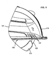
- FIG. 1 is a sectional plan view showing a dust collecting circular saw according to a representative embodiment in its entirety except part of a motor housing and a driving motor.
- FIG. 2 is a right side view of a blade case, in which the motor housing and a base are deleted.
- FIG. 3 is a left side view of the blade case, in which a dust case and the base are deleted.
- FIG. 4 is a sectional front view showing the dust collecting circular saw as taken along a line slightly displaced rearward of the axis of rotation of the driving motor.
- FIG. 5 is a side view of a forward end part of the circular saw as viewed from the left side of FIG. 1.
-
- The representative dust collecting typed circular saw according to the invention may include a blade that cuts a workpiece, a motor that drives the blade, a cooling fan that generates a cooling air to cool the motor, a dust case that collects chips generated during the cutting operation by the blade, a dust case cover that covers at least part of the outside surface of the dust case and air space formed between the dust case cover and the dust case, wherein the cooling air is introduced into the air space. The representative circular saw is preferably applied to cut metal workpiece such as a steel material and an iron plate, while it can also be applied to cut wood or stone. Typically, when cutting metal workpiece, hot metal chips may be generated during the cutting operation and such hot chips may heat the dust case when chips are collected into the dust case. To cope with such heating, the representative circular saw introduces the cooling air to cool the motor into the air space between the heated dust case and the dust case cover. As a result, heat transfer from the dust case to the dust case cover can be prevented and therefore, the user can be securely escaped from directly contacting any heated members of the circular saw. Further, according to the invention, while the cooling air can actively cool the outside surface of the dust case, chips within the dust case do not escape to the outside because the cooling air is not introduced into the dust case.
- Each of the additional features and method steps disclosed above and below may be utilized separately or in conjunction with other features and method steps to provide and manufacture improved circular saws and method for using such circular saws and devices utilized therein. Representative examples of the present invention, which examples utilized many of these additional features and method steps in conjunction, will now be described in detail with reference to the drawings. This detailed description is merely intended to teach a person skilled in the art further details for practicing preferred aspects of the present teachings and is not intended to limit the scope of the invention. Only the claims define the scope of the claimed invention. Therefore, combinations of features and steps disclosed within the following detailed description may not be necessary to practice the invention in the broadest sense, and are instead taught merely to particularly describe some representative examples of the invention, which detailed description will now be given with reference to the accompanying drawings.
- A representative embodiment of the present invention is explained with reference to FIGS. 1 to 5. In FIGS., flow of cooling air and flow of chips are shown by thick arrows and thin arrows, respectively. The dust collecting
circular saw 101 according to the representative embodiment is designed for cutting metal workpiece such as a steel material and an iron plate. Thecircular saw 101 includes acircular saw body 103, abase 105 and adust case 107. Thebase 105 is connected to thebody 103 and placed in use on a workpiece (not shown). Thedust case 107 is removably attached to thebody 103 and chips generated during the cutting operation are collected in thedust case 107. - As shown in FIG. 1, a
motor housing 111 and ablade case 113 is connected together to define thecircular saw body 103. Themotor housing 111 houses a drivingmotor 121 and acooling fan 131. Thecooling fan 131 is mounted on adriving shaft 123 of thedriving motor 121 and rotated together with thedriving shaft 123 when thedriving motor 121 is driven. - The
blade case 113 houses ablade 129. Asafety cover 115 is retractably attached to the lower region of theblade case 113. As shown in FIGS. 2 and 3, theblade case 113 has ahandgrip 117 and acircular gear housing 114. Thehandgrip 117 is formed on the rearward outer circumferential portion of theblade case 113. Thegear housing 114 is integrally formed on the side of theblade case 113 and bulges toward themotor housing 111. Thehandgrip 117 has atrigger 117a operated to start and stop the drivingmotor 117. As shown in FIG. 1, the side peripheral edge portion or the end surface of thegear housing 114 which bulges toward themotor housing 111 butts the open end surface of themotor housing 111 and is connected to themotor housing 111 by bolts (not shown). - A driven gear 133 (not shown) and a spindle 125 (see FIG. 3) are disposed within the
gear housing 114 in a position corresponding to the position of the end of thedriving shaft 123 that extends toward thegear housing 114. The driven gear is mounted on one end of thespindle 125 and ablade 129 is mounted on the other end of thespindle 125. Thespindle 125, theblade 129 and the driven gear can rotate together in one piece. A driving gear 123a is formed on the end of thedriving shaft 123 and engages the driven gear. Thus, the rotation of thedriving motor 121 is transmitted to theblade 129 via thespindle 125 while being decelerated between the driving gear 123a and the driven gear. Thus, theblade 129 is rotated and cuts a workpiece. - As shown in FIG. 3, the
safety cover 115 is mounted on thespindle 125 and can rotate with respect to thespindle 125 via arotation sliding portion 115a. Thesafety cover 115 is normally protruded from the underside of thebase 105 by a biasing device (not shown) including a spring and covers the lower edge portion of theblade 129 for cutting a metal workpiece. When thebase 105 is placed on the workpiece to be cut, thesafety cover 115 is pushed and retracted by the workpiece, so that thesafety cover 115 exposes the lower edge portion of theblade 129 and is housed within theblade case 113. - Chips are generated by cutting the metal workpiece with the
blade 129 and fly out in the tangential direction of theblade 129. Specifically, as shown by the thin arrows in FIG. 3, the chips fly upward into theblade case 113 and move toward achip outlet 113b along an innercircumferential surface 113a of the peripheral wall of theblade case 113 or its vicinity. Thechip outlet 113b is formed in the upper portion of the side wall surface of theblade case 113 on the side of thedust case 107. The metal workpiece generates relatively hot metal chips when being cut by theblade 129. Thus, the metal chips fly out into theblade case 113 generally heat theblade case 113. Therefore, theblade case 113 is made of metal such as aluminum alloy in consideration of heat resistance, while the outer surface of theblade case 113 becomes hot due to such hot metal chips. - In view of this fact, in order to prevent the user from directly contacting the outside surface of the
blade case 113, as shown in FIGS. 1 and 4, the entire outside surface of theblade case 113 including thegear housing 114, i.e. the side wall surface on the side of themotor housing 111, the side wall surface on the side of thedust case 107 and the peripheral wall surface connecting the both side wall surfaces, is covered with ablade case cover 119 formed of heat-resistant material, such as synthetic resin or synthetic rubber. In this case, an appropriate clearance is provided between theblade case 113 and theblade case cover 119 so that a double wall having so-called air space is formed. Theblade case cover 119 is removably connected to theblade case 113 by fastening means such as screws. - As shown in FIGS. 1 and 4, the
dust case 107 is disposed on the opposite side of themotor housing 111 with respect to theblade case 113. Thedust case 107 is removably attached by a fastening device (not shown) to the side wall surface of theblade case 113 which faces thedust case 107. Thedust case 107 has a dust collecting inlet (not shown) formed in a position to face thechip outlet 113b of theblade case 113. Hot chips flow into adust collecting chamber 107a via the dust collecting inlet. Thedust case 107 is formed of metal such as aluminum alloy in consideration of heat resistance against the hot meal chips. Thedust case 107 may be heated by the collected chips and its outside surface may become hot. In view of this fact, in order to prevent the user from directly contacting the outside surface of thedust case 107, the entire outside surface is covered with adust case cover 141 formed of heat-resistant material such as synthetic resin or synthetic rubber. - The
dust case cover 141 is arranged at a predetermined distance from the outside surface of thedust case 107, so thatair space 143 is formed between thedust case 107 and thedust case cover 141. Thedust case cover 141 has a bowl-like shape similar to the contours of thedust case 107. Thedust case cover 141 is removably connected to thedust case 107 by fastening device such as screws, with the open peripheral edge portion of thedust case cover 141 in contact with the outside surface of thedust case 107 or theblade case cover 119. - When the driving
motor 121 is driven, the coolingfan 131 on the drivingshaft 123 of the drivingmotor 121 draws outside air into themotor housing 111 through an air intake (not shown) formed in a portion (the axial end) of themotor housing 111. The intake air flows within themotor housing 111, thereby cooling the drivingmotor 121. Thereafter, the air flows out into thegear housing 114 through the coolingfan 131. As shown in FIGS. 1 and 2, a generally annular coolingair outflow passage 145 is formed in the side surface of thegear housing 114 which faces the coolingfan 131. The coolingair outflow passage 145 is defined by denting the side surface of thegear housing 114 inward (leftward as viewed in the drawings) and receives the cooling air which flows out of themotor housing 111 in the axial direction of the coolingfan 131. - As shown by thick arrows in FIG. 2, the cooling air flows out into the cooling
air outflow passage 145 and then into a coolingair outflow space 147 above the outer peripheral portion of thegear housing 114. Then, the cooling air branches out into three flows in the coolingair outflow space 147. The coolingair outflow space 147 is defined between theblade case 113 and theblade case cover 119 by denting a portion of the side surface of theblade case 113 on the side of themotor housing 111 inward of theblade case 113. - One of the three flows of the cooling air forms a first flow that is led into the
air space 143 via a plurality of slit-like communication apertures 149 in the side wall surface of theblade case 113. A first passage of the first flow is defined by thecommunication apertures 149. Thecommunication apertures 149 are formed near the upper portion of the side wall surface of theblade case 113 to allow communication between the coolingair outflow space 147 and theair space 143. The cooling air is introduced into theair space 143 through thecommunication apertures 149 and serves to cool the outside surface of thedust case 107. Thereafter, the cooling air is discharged obliquely downward to the outside through a plurality of slit-like exhaust apertures 151. Theexhaust apertures 151 are formed in the lower forward end portion of thedust case cover 141. - Another flow of the cooling air forms a second flow that serves to cool the outside surface of the
blade case 113. A second passage of the second flow is defined by aclearance 155, a coolingair guide passage 153 and aspout 157. Theclearance 155 is defined between theblade case 113 and theblade case cover 119. The cooling air is led from the coolingair outflow space 147 to theclearance 155 via the coolingair guide passage 153. The cooling air serves to cool theblade case 113 by flowing through theclearance 155. The cooling air is then discharged to the outside through thespout 157. The coolingair guide passage 153 is defined by denting a portion of the side surface of theblade case 113 on the side of themotor housing 111 inward of theblade case 113. Further, thespout 157 is formed in the lower forward end of theblade case cover 119 such that the cooling air is blown on the upper surface of thebase 105, or more specifically, toward a bladeposition check notch 161 as shown in FIG. 1. - The
notch 161 is formed in the forward end portion of thebase 105 and indicates a cutting line along which cutting is performed by theblade 129. The coolingair guide passage 153, theclearance 155 and thespout 157 correspond to the "exhaust passage" according to the invention. Further, thenotch 161 corresponds to the "mark" according to the invention. The coolingair outflow space 147, the coolingair guide passage 153 and theclearance 155 are defined by theblade case 113 and theblade case cover 119 and form air space between theblade case 113 and theblade case cover 119. - The other flow of the cooling air forms a third flow that is introduced into the
blade case 113. The third flow serves to reduce the tendency that the chips fly from theblade case 113 to thegear housing 114. In other words, it serves to assist the chips in moving toward thechip outlet 113b. A third passage of the third flow is defined by aguide hole 159. Theguide hole 159 is formed in the forward portion of the wall surface that defines the coolingair outflow space 147. Theguide hole 159 is formed above the center of rotation of theblade 129 and opens in the direction that allows the cooling air to be discharged generally horizontally in the forward direction. Specifically, theguide hole 159 opens in such a direction that the direction of discharge of the cooling air into theblade case 113 crosses the direction in which the chips fly out into theblade case 113 by the operation of cutting the workpiece and coincides with the direction in which the cooling air guides the chips toward the innercircumferential surface 113a of theblade case 113. Theguide hole 159 is a feature that corresponds to the "cooling air guide" according to the invention. - Operation of the dust collecting
circular saw 101 is now explained. Thebase 105 is placed on a workpiece to be cut and thetrigger 117a is operated by the user to drive the drivingmotor 121. Thus, theblade 129 is rotated via the drivingshaft 123 and thespindle 125. In this state, thecircular saw 101 is slid forward on the workpiece, so that the workpiece is cut by theblade 129. - When the driving
motor 121 is driven, the coolingfan 131 rotates together with the drivingshaft 123 and draws the cooling air into themotor housing 111. Then, as shown by the thick arrows in FIG. 1, the cooling air flows axially within themotor housing 111, thereby cooling the drivingmotor 121. Thereafter, the cooling air flows out into the coolingair outflow passage 145 of thegear housing 114 and then into the coolingair outflow space 147. Part of the cooling air which has flown into the coolingair outflow space 147 is led into theair space 143 of thedust case 107 through thecommunication apertures 149 as shown by the thick arrow in FIG. 2. Then, the cooling air cools the outside surface of thedust case 107 by flowing through theair space 143 as shown by the thick arrows in FIGS. 1 and 4. Thereafter, the cooling air is discharged to the outside through theexhaust apertures 151. - The outside surface of the
dust case 107 is covered with thedust case cover 141, and theair space 143 is provided between thedust case 107 and thedust case cover 141. Therefore, theair space 143 serves to prevent heat transfer from thedust case 107 to thedust case cover 141. Moreover, heat dissipated from the outside surface of thedust case 107 is actively released to the outside by means of the cooling air flowing through theair space 143, so that the outside surface of thedust case 107 can be cooled. Further, with the construction in which thedust case cover 141 covers almost the entire outside surface of thedust case 107, user may directly contact the outside surface of thedust case 107 during cutting operation. - Further, another part of the cooling air which has flown into the cooling
air outflow space 147 is led through the coolingair guide passage 153 into theclearance 155 formed between theblade case 113 and theblade case cover 119 as shown by the thick arrows in FIG. 2. Then, the cooling air cools the outside surface of theblade case 113 by flowing through theclearance 155. Thereafter, as shown in FIG. 1, the cooling air is discharged onto the upper surface of the base 105 toward thenotch 161 through thespout 157. At this time, the cooling air blows away chips around thenotch 161 on thebase 105, so that the user can readily check the position of theblade 129. - Further, the other part of the cooling air which has flown into the cooling
air outflow space 147 is introduced into theblade case 113 via theguide hole 159. Then, as shown by the thick arrow in FIG. 3, the cooling air is discharged generally horizontally in the forward direction from above the center of rotation of theblade 129. This flow serves to reduce the tendency that the chips generated by the cutting operation of theblade 129 fly toward thegear housing 114. Specifically, the flow acts upon the chips (shown by the thin arrows) that fly out into theblade case 113 during the cutting operation, such that the chips are guided toward the innercircumferential surface 113a of theblade case 113. Thus, the chips flow upward toward thechip outlet 113b along the innercircumferential surface 113a of theblade case 113. Then, the chips are discharged from thechip outlet 113b into thedust case 107. As a result, chip collection efficiency is enhanced. Further, by reducing the tendency that the chips fly toward thegear housing 114 or toward the center of theblade case 113, chips can be effectively kept out of therotation sliding portion 115a of thesafety cover 115 disposed within theblade case 113. Thus, chips can be effectively prevented from being caught in therotation sliding portion 115a. - Further, the invention can be applied to a dust collecting circular saw not only for metal cutting but also for wood or stone cutting. Besides the above described embodiment, the
air space 143 may be divided by a partition such that a passage, e.g. a meander passage (winding passage) like a winding maze, is formed within theair space 143. In this case, the cooling air led into theair space 143 via thecommunication apertures 149 flows through the meander passage and is discharged to the outside from theexhaust apertures 151. With this construction, residence time of the cooling air within theair space 143 can be elongated, so that the effectiveness of cooling thedust case 107 can be enhanced. Further, beside the representative embodiment, the air space 143may be formed in layers on the outside surface of thedust case 107. Further, thedust case cover 141 may cover only part of the outside surface of thedust case 113. - It is explicitly stated that all features disclosed in the description and/or the claims are intended to be disclosed separately and independently from each other for the purpose of original disclosure as well as for the purpose of restricting the claimed invention independent of the composition of the features in the embodiments and/or the claims. It is explicitly stated that all value ranges or indications of groups of entities disclose every possible intermediate value or intermediate entity for the purpose of original disclosure as well as for the purpose of restricting the claimed invention, in particular as limits of value ranges.
-
- 101
- dust collecting circular saw
- 103
- circular saw body
- 105
- base
- 107
- dust case
- 107a
- dust collecting chamber
- 111
- motor housing
- 113
- blade case
- 113a
- inner circumferential surface
- 113b
- chip outlet
- 114
- gear housing
- 115
- safety cover
- 115a
- rotation sliding portion
- 117
- handgrip
- 117a
- trigger
- 119
- blade case cover
- 121
- driving motor
- 123
- driving shaft
- 123a
- driving gear.
- 125
- spindle
- 129
- blade
- 131
- cooling fan
- 141
- dust case cover
- 143
- air space
- 145
- cooling air outflow passage
- 147
- cooling air outflow space
- 149
- communication aperture (cooling air guide)
- 151
- exhaust aperture
- 153
- cooling air guide passage (exhaust passage)
- 155
- clearance (exhaust passage)
- 157
- spout (exhaust passage)
- 159
- guide hole (cooling air guide)
- 161
- notch (mark)
- It is explicitly stated that all features disclosed in the description and/or the claims are intended to be disclosed separately and independently from each other for the purpose of original disclosure as well as for the purpose of restricting the claimed invention independent of the compositions of the features in the embodiments and/or the claims. It is explicitly stated that all value ranges or indications of groups of entities disclose every possible intermediate value or intermediate entity for the purpose of original disclosure as well as for the purpose of restricting the claimed invention, in particular as limits of value ranges.
Claims (9)
- A circular saw comprising a blade that cuts a workpiece, a motor that drives the blade, a cooling fan that generates a cooling air to cool the motor, a dust case that collects chips generated during the cutting operation by the blade, a dust case cover that covers at least part of the outside surface of the dust case,
characterized in that air space is formed between the dust case cover and the dust case and the cooling air is introduced into the air space. - The circular saw as defined in claim 1, wherein the dust case cover is provided substantially on the entire outside surface of the dust case.
- The circular saw as defined in claim 1 or 2, further comprising a blade case that covers the blade, a blade case cover that covers the outside surface of the blade case, an exhaust passage formed between the blade case and the blade case cover, a base connected to the blade case and a blade position check mark provided on the base to perform the cutting operation by the blade, wherein the cooling air to cool the motor is introduced into the exhaust passage and led through the exhaust passage along the outside surface of the blade case and then blown out toward the mark on the upper surface of the base.
- The circular saw as defined in any one of claims 1 to 3, further comprising a blade case that covers the blade, a cooling air guide that guides the cooling air to cool the motor into the blade case, wherein the cooling air introduced into the blade case by the cooling air guide introduces the chips within the blade case into the dust case.
- The circular saw as defined in any one of claims 1 to 4, wherein the blade is arranged to cut metal workpiece, hot metal chips generated during the workpiece cutting operation is collected within the dust case, and air space prevents the heat propagation of the hot chips from the dust case to the dust case cover.
- The circular saw as defined in claim 5 further comprising a blade case that covers the blade, a cooling air guide that guides the cooling air to cool the motor into the blade case, wherein the direction of guiding the cooling air into the blade case crosses the direction in which the chips fly out into the blade case by the operation of cutting the workpiece and coincides with the direction in which the cooling air guides the chips toward the inner circumferential surface of the blade case.
- The circular saw as defined in any one of claims 1 to 6, wherein the air space comprises a winding passage to meander the cooling air within the air space.
- The circular saw as defined in any one of claims 1 to 7, wherein air space comprises a plurality of air layers from the dust case to the dust case cover.
- A circular saw comprising a blade that cuts a metal workpiece, a motor that drives the blade, a cooling fan that generates a cooling air to cool the motor, a dust case that collects chips generated during the cutting operation by the blade, and a blade case that covers the blade,
characterized by a cooling air guide that guides the cooling air into the blade case, wherein the direction of guiding the cooling air into the blade case crosses the direction in which the chips fly out into the blade case by the operation of cutting the workpiece and coincides with the direction in which the cooling air guides the chips toward the inner circumferential surface of the blade case.
Applications Claiming Priority (2)
| Application Number | Priority Date | Filing Date | Title |
|---|---|---|---|
| JP2003409070A JP4467964B2 (en) | 2003-12-08 | 2003-12-08 | Dust collection circular saw |
| JP2003409070 | 2003-12-08 |
Publications (2)
| Publication Number | Publication Date |
|---|---|
| EP1541269A1 true EP1541269A1 (en) | 2005-06-15 |
| EP1541269B1 EP1541269B1 (en) | 2007-05-23 |
Family
ID=34510469
Family Applications (1)
| Application Number | Title | Priority Date | Filing Date |
|---|---|---|---|
| EP20040028742 Active EP1541269B1 (en) | 2003-12-08 | 2004-12-03 | Circular saw |
Country Status (4)
| Country | Link |
|---|---|
| US (1) | US7628102B2 (en) |
| EP (1) | EP1541269B1 (en) |
| JP (1) | JP4467964B2 (en) |
| DE (1) | DE602004006589T2 (en) |
Cited By (2)
| Publication number | Priority date | Publication date | Assignee | Title |
|---|---|---|---|---|
| FR2917000A1 (en) * | 2007-06-11 | 2008-12-12 | Paul Parisse | Circular saw for cutting wooden plate, has duct connecting release orifice and inlet opening, where duct is oriented such that axis is directed towards base of concave curved wall that closes ends of reception volume |
| CN111531220A (en) * | 2020-05-11 | 2020-08-14 | 龙南格林园艺制品有限公司 | Full-automatic guillootine |
Families Citing this family (14)
| Publication number | Priority date | Publication date | Assignee | Title |
|---|---|---|---|---|
| JP4762642B2 (en) * | 2005-08-19 | 2011-08-31 | 株式会社マキタ | Cutting machine |
| US20100058911A1 (en) * | 2008-09-11 | 2010-03-11 | Jay Aaron Goddard | Blade Guard for Power Tool Having an Evacuation System |
| US20110079125A1 (en) * | 2009-10-01 | 2011-04-07 | Hsin-Cheng Kuo | Circular Saw |
| US9463546B1 (en) | 2011-04-13 | 2016-10-11 | Skitter & Squirt Adventures, LLC. | System and method for dissipating heat from a rotary power tool |
| US9089941B2 (en) * | 2011-09-30 | 2015-07-28 | Robert Bosch Gmbh | Circular saw guard system |
| JP2014148006A (en) * | 2013-02-01 | 2014-08-21 | Makita Corp | Electric power tool and portable circular saw |
| KR20140145478A (en) * | 2013-06-13 | 2014-12-23 | 동일정밀공업 주식회사 | Air heater |
| JP6380931B2 (en) | 2014-09-12 | 2018-08-29 | パナソニックIpマネジメント株式会社 | Electric circular saw |
| WO2018100940A1 (en) * | 2016-11-30 | 2018-06-07 | 日立工機株式会社 | Power-driven tool |
| EP3765226B1 (en) | 2018-03-16 | 2023-11-01 | Milwaukee Electric Tool Corporation | Blade clamp for power tool, reciprocating power tool, and method of operating such a blade clamp |
| USD887806S1 (en) | 2018-04-03 | 2020-06-23 | Milwaukee Electric Tool Corporation | Jigsaw |
| US11014176B2 (en) | 2018-04-03 | 2021-05-25 | Milwaukee Electric Tool Corporation | Jigsaw |
| EP3659763B1 (en) | 2018-11-28 | 2023-05-31 | Black & Decker Inc. | Power tool |
| JP7468154B2 (en) | 2020-05-29 | 2024-04-16 | 工機ホールディングス株式会社 | Work Machine |
Citations (4)
| Publication number | Priority date | Publication date | Assignee | Title |
|---|---|---|---|---|
| JPH01148502A (en) * | 1987-12-04 | 1989-06-09 | Hitachi Koki Co Ltd | Dust collecting mechanism of portable dust collecting circular saw |
| JPH06190628A (en) * | 1992-12-22 | 1994-07-12 | Makita Corp | Circular saw device |
| US5701676A (en) * | 1995-05-09 | 1997-12-30 | Makita Corporation | Portable rotary saw |
| US6009782A (en) * | 1997-06-19 | 2000-01-04 | Makita Corporation | Table saw |
Family Cites Families (10)
| Publication number | Priority date | Publication date | Assignee | Title |
|---|---|---|---|---|
| US4675999A (en) * | 1984-11-16 | 1987-06-30 | Hitachi Koki Company, Ltd. | Portable power tool equipped with dust collector |
| DE3843236A1 (en) * | 1988-12-22 | 1990-06-28 | Bosch Gmbh Robert | Circular saw |
| FR2649746B1 (en) | 1989-07-13 | 1995-07-07 | Ferco Int Usine Ferrures | INSTALLATION FOR THE AUTOMATIC ASSEMBLY OF A FASTENING DEVICE, PARTICULARLY A SIDE LOCK TO BE MOUNTED ON OPENING ELEMENTS, ESPECIALLY OSCILLO-HINGED WINDOWS |
| JPH0644652Y2 (en) * | 1990-03-15 | 1994-11-16 | リョービ株式会社 | Electric cutting cutter with dust collector |
| US5074044A (en) * | 1991-04-26 | 1991-12-24 | Duncan C Warren | Dust disposal attachment for a rotary element of a power tool |
| JP2752811B2 (en) | 1991-08-05 | 1998-05-18 | 日本電気株式会社 | Transmission speed switching method |
| JP2561668Y2 (en) * | 1991-11-08 | 1998-02-04 | 日立工機株式会社 | Portable dust collection circular saw |
| JPH0541702U (en) * | 1991-11-14 | 1993-06-08 | 日立工機株式会社 | Portable dust collecting circular saw |
| JP3072537U (en) * | 2000-04-14 | 2000-10-20 | 優 下田 | Electric saw |
| JP4656806B2 (en) * | 2002-11-01 | 2011-03-23 | 株式会社マキタ | Electric tool |
-
2003
- 2003-12-08 JP JP2003409070A patent/JP4467964B2/en not_active Expired - Lifetime
-
2004
- 2004-12-03 DE DE200460006589 patent/DE602004006589T2/en active Active
- 2004-12-03 EP EP20040028742 patent/EP1541269B1/en active Active
- 2004-12-08 US US11/009,936 patent/US7628102B2/en active Active
Patent Citations (4)
| Publication number | Priority date | Publication date | Assignee | Title |
|---|---|---|---|---|
| JPH01148502A (en) * | 1987-12-04 | 1989-06-09 | Hitachi Koki Co Ltd | Dust collecting mechanism of portable dust collecting circular saw |
| JPH06190628A (en) * | 1992-12-22 | 1994-07-12 | Makita Corp | Circular saw device |
| US5701676A (en) * | 1995-05-09 | 1997-12-30 | Makita Corporation | Portable rotary saw |
| US6009782A (en) * | 1997-06-19 | 2000-01-04 | Makita Corporation | Table saw |
Non-Patent Citations (2)
| Title |
|---|
| PATENT ABSTRACTS OF JAPAN vol. 018, no. 538 (M - 1686) 13 October 1994 (1994-10-13) * |
| PATENT ABSTRACTS OF JAPAN vol. 2000, no. 17 5 June 2001 (2001-06-05) * |
Cited By (2)
| Publication number | Priority date | Publication date | Assignee | Title |
|---|---|---|---|---|
| FR2917000A1 (en) * | 2007-06-11 | 2008-12-12 | Paul Parisse | Circular saw for cutting wooden plate, has duct connecting release orifice and inlet opening, where duct is oriented such that axis is directed towards base of concave curved wall that closes ends of reception volume |
| CN111531220A (en) * | 2020-05-11 | 2020-08-14 | 龙南格林园艺制品有限公司 | Full-automatic guillootine |
Also Published As
| Publication number | Publication date |
|---|---|
| JP4467964B2 (en) | 2010-05-26 |
| JP2005169519A (en) | 2005-06-30 |
| DE602004006589D1 (en) | 2007-07-05 |
| EP1541269B1 (en) | 2007-05-23 |
| DE602004006589T2 (en) | 2008-01-31 |
| US20050120845A1 (en) | 2005-06-09 |
| US7628102B2 (en) | 2009-12-08 |
Similar Documents
| Publication | Publication Date | Title |
|---|---|---|
| US7628102B2 (en) | Circular saws | |
| EP1415746B1 (en) | Power tool | |
| US7302947B2 (en) | Cutting machine with environment control arrangement | |
| US7219435B2 (en) | Portable electric cutting device with blower mechanism | |
| JP2739861B2 (en) | Hand held circular saw | |
| EP3099455B1 (en) | Airflow managemnet system for a power tool | |
| EP1708858B1 (en) | Power circular saw with blower system and bevel quadrant | |
| GB2423272A (en) | Electric power tool with heat sink | |
| US20090165312A1 (en) | Hand-held power tool | |
| EP1584423A2 (en) | Power tool | |
| JPH06173797A (en) | Intake device for engine | |
| CN102639857A (en) | Hand-held work apparatus powered by internal combustion engine | |
| JP4899033B2 (en) | Blower working machine and blower casing | |
| JP2013189948A (en) | Engine and engine working machine | |
| JP2007218186A (en) | Engine cooling structure of portable air blowing work machine | |
| JP2002210705A (en) | Chain saw | |
| WO2009038453A1 (en) | Electric hand tool with improved dust disposal | |
| WO2022044771A1 (en) | Work machine | |
| JP2006159373A (en) | Power tool | |
| EP2079919B1 (en) | Crankcase and internal combustion engine unit | |
| JP3353128B2 (en) | Tabletop circular saw machine | |
| JP7468154B2 (en) | Work Machine | |
| JPH085766Y2 (en) | Portable electric circular saw dust discharge structure | |
| JPH0541702U (en) | Portable dust collecting circular saw | |
| JP2010105463A (en) | Drive section structure of working vehicle |
Legal Events
| Date | Code | Title | Description |
|---|---|---|---|
| PUAI | Public reference made under article 153(3) epc to a published international application that has entered the european phase |
Free format text: ORIGINAL CODE: 0009012 |
|
| AK | Designated contracting states |
Kind code of ref document: A1 Designated state(s): AT BE BG CH CY CZ DE DK EE ES FI FR GB GR HU IE IS IT LI LT LU MC NL PL PT RO SE SI SK TR |
|
| AX | Request for extension of the european patent |
Extension state: AL BA HR LV MK YU |
|
| 17P | Request for examination filed |
Effective date: 20050530 |
|
| AKX | Designation fees paid |
Designated state(s): DE FR GB |
|
| GRAP | Despatch of communication of intention to grant a patent |
Free format text: ORIGINAL CODE: EPIDOSNIGR1 |
|
| GRAS | Grant fee paid |
Free format text: ORIGINAL CODE: EPIDOSNIGR3 |
|
| GRAA | (expected) grant |
Free format text: ORIGINAL CODE: 0009210 |
|
| AK | Designated contracting states |
Kind code of ref document: B1 Designated state(s): DE FR GB |
|
| REG | Reference to a national code |
Ref country code: GB Ref legal event code: FG4D |
|
| REF | Corresponds to: |
Ref document number: 602004006589 Country of ref document: DE Date of ref document: 20070705 Kind code of ref document: P |
|
| ET | Fr: translation filed | ||
| PLBE | No opposition filed within time limit |
Free format text: ORIGINAL CODE: 0009261 |
|
| STAA | Information on the status of an ep patent application or granted ep patent |
Free format text: STATUS: NO OPPOSITION FILED WITHIN TIME LIMIT |
|
| 26N | No opposition filed |
Effective date: 20080226 |
|
| REG | Reference to a national code |
Ref country code: FR Ref legal event code: PLFP Year of fee payment: 12 |
|
| REG | Reference to a national code |
Ref country code: FR Ref legal event code: PLFP Year of fee payment: 13 |
|
| REG | Reference to a national code |
Ref country code: FR Ref legal event code: PLFP Year of fee payment: 14 |
|
| PGFP | Annual fee paid to national office [announced via postgrant information from national office to epo] |
Ref country code: GB Payment date: 20231102 Year of fee payment: 20 |
|
| PGFP | Annual fee paid to national office [announced via postgrant information from national office to epo] |
Ref country code: FR Payment date: 20231108 Year of fee payment: 20 Ref country code: DE Payment date: 20231031 Year of fee payment: 20 |