EP1540613B1 - Intelligentes behälterüberwachungssystem - Google Patents
Intelligentes behälterüberwachungssystem Download PDFInfo
- Publication number
- EP1540613B1 EP1540613B1 EP03791154A EP03791154A EP1540613B1 EP 1540613 B1 EP1540613 B1 EP 1540613B1 EP 03791154 A EP03791154 A EP 03791154A EP 03791154 A EP03791154 A EP 03791154A EP 1540613 B1 EP1540613 B1 EP 1540613B1
- Authority
- EP
- European Patent Office
- Prior art keywords
- shipping container
- wireless communicator
- remotely monitorable
- communicator
- wireless
- Prior art date
- Legal status (The legal status is an assumption and is not a legal conclusion. Google has not performed a legal analysis and makes no representation as to the accuracy of the status listed.)
- Expired - Lifetime
Links
Images


Classifications
-
- E—FIXED CONSTRUCTIONS
- E05—LOCKS; KEYS; WINDOW OR DOOR FITTINGS; SAFES
- E05B—LOCKS; ACCESSORIES THEREFOR; HANDCUFFS
- E05B39/00—Locks giving indication of authorised or unauthorised unlocking
-
- G—PHYSICS
- G08—SIGNALLING
- G08B—SIGNALLING OR CALLING SYSTEMS; ORDER TELEGRAPHS; ALARM SYSTEMS
- G08B25/00—Alarm systems in which the location of the alarm condition is signalled to a central station, e.g. fire or police telegraphic systems
- G08B25/01—Alarm systems in which the location of the alarm condition is signalled to a central station, e.g. fire or police telegraphic systems characterised by the transmission medium
- G08B25/10—Alarm systems in which the location of the alarm condition is signalled to a central station, e.g. fire or police telegraphic systems characterised by the transmission medium using wireless transmission systems
-
- E—FIXED CONSTRUCTIONS
- E05—LOCKS; KEYS; WINDOW OR DOOR FITTINGS; SAFES
- E05B—LOCKS; ACCESSORIES THEREFOR; HANDCUFFS
- E05B39/00—Locks giving indication of authorised or unauthorised unlocking
- E05B39/005—Locks with means for tracking the location of locked items, e.g. freight containers
-
- E—FIXED CONSTRUCTIONS
- E05—LOCKS; KEYS; WINDOW OR DOOR FITTINGS; SAFES
- E05B—LOCKS; ACCESSORIES THEREFOR; HANDCUFFS
- E05B83/00—Vehicle locks specially adapted for particular types of wing or vehicle
- E05B83/02—Locks for railway freight-cars, freight containers or the like; Locks for the cargo compartments of commercial lorries, trucks or vans
- E05B83/08—Locks for railway freight-cars, freight containers or the like; Locks for the cargo compartments of commercial lorries, trucks or vans with elongated bars for actuating the fastening means
- E05B83/10—Rotary bars
-
- G—PHYSICS
- G06—COMPUTING OR CALCULATING; COUNTING
- G06K—GRAPHICAL DATA READING; PRESENTATION OF DATA; RECORD CARRIERS; HANDLING RECORD CARRIERS
- G06K19/00—Record carriers for use with machines and with at least a part designed to carry digital markings
- G06K19/06—Record carriers for use with machines and with at least a part designed to carry digital markings characterised by the kind of the digital marking, e.g. shape, nature, code
- G06K19/067—Record carriers with conductive marks, printed circuits or semiconductor circuit elements, e.g. credit or identity cards also with resonating or responding marks without active components
- G06K19/07—Record carriers with conductive marks, printed circuits or semiconductor circuit elements, e.g. credit or identity cards also with resonating or responding marks without active components with integrated circuit chips
- G06K19/077—Constructional details, e.g. mounting of circuits in the carrier
- G06K19/07749—Constructional details, e.g. mounting of circuits in the carrier the record carrier being capable of non-contact communication, e.g. constructional details of the antenna of a non-contact smart card
- G06K19/07798—Constructional details, e.g. mounting of circuits in the carrier the record carrier being capable of non-contact communication, e.g. constructional details of the antenna of a non-contact smart card part of the antenna or the integrated circuit being adapted for rupturing or breaking, e.g. record carriers functioning as sealing devices for detecting not-authenticated opening of containers
-
- G—PHYSICS
- G07—CHECKING-DEVICES
- G07C—TIME OR ATTENDANCE REGISTERS; REGISTERING OR INDICATING THE WORKING OF MACHINES; GENERATING RANDOM NUMBERS; VOTING OR LOTTERY APPARATUS; ARRANGEMENTS, SYSTEMS OR APPARATUS FOR CHECKING NOT PROVIDED FOR ELSEWHERE
- G07C11/00—Arrangements, systems or apparatus for checking, e.g. the occurrence of a condition, not provided for elsewhere
-
- G—PHYSICS
- G07—CHECKING-DEVICES
- G07C—TIME OR ATTENDANCE REGISTERS; REGISTERING OR INDICATING THE WORKING OF MACHINES; GENERATING RANDOM NUMBERS; VOTING OR LOTTERY APPARATUS; ARRANGEMENTS, SYSTEMS OR APPARATUS FOR CHECKING NOT PROVIDED FOR ELSEWHERE
- G07C5/00—Registering or indicating the working of vehicles
- G07C5/008—Registering or indicating the working of vehicles communicating information to a remotely located station
-
- G—PHYSICS
- G07—CHECKING-DEVICES
- G07C—TIME OR ATTENDANCE REGISTERS; REGISTERING OR INDICATING THE WORKING OF MACHINES; GENERATING RANDOM NUMBERS; VOTING OR LOTTERY APPARATUS; ARRANGEMENTS, SYSTEMS OR APPARATUS FOR CHECKING NOT PROVIDED FOR ELSEWHERE
- G07C5/00—Registering or indicating the working of vehicles
- G07C5/08—Registering or indicating performance data other than driving, working, idle, or waiting time, with or without registering driving, working, idle or waiting time
- G07C5/0841—Registering performance data
-
- G—PHYSICS
- G08—SIGNALLING
- G08B—SIGNALLING OR CALLING SYSTEMS; ORDER TELEGRAPHS; ALARM SYSTEMS
- G08B13/00—Burglar, theft or intruder alarms
- G08B13/02—Mechanical actuation
- G08B13/08—Mechanical actuation by opening, e.g. of door, of window, of drawer, of shutter, of curtain, of blind
-
- G—PHYSICS
- G08—SIGNALLING
- G08B—SIGNALLING OR CALLING SYSTEMS; ORDER TELEGRAPHS; ALARM SYSTEMS
- G08B13/00—Burglar, theft or intruder alarms
- G08B13/02—Mechanical actuation
- G08B13/12—Mechanical actuation by the breaking or disturbance of stretched cords or wires
- G08B13/126—Mechanical actuation by the breaking or disturbance of stretched cords or wires for a housing, e.g. a box, a safe, or a room
-
- G—PHYSICS
- G08—SIGNALLING
- G08B—SIGNALLING OR CALLING SYSTEMS; ORDER TELEGRAPHS; ALARM SYSTEMS
- G08B13/00—Burglar, theft or intruder alarms
- G08B13/02—Mechanical actuation
- G08B13/14—Mechanical actuation by lifting or attempted removal of hand-portable articles
- G08B13/1445—Mechanical actuation by lifting or attempted removal of hand-portable articles with detection of interference with a cable tethering an article, e.g. alarm activated by detecting detachment of article, breaking or stretching of cable
- G08B13/1463—Physical arrangements, e.g. housings
-
- G—PHYSICS
- G08—SIGNALLING
- G08B—SIGNALLING OR CALLING SYSTEMS; ORDER TELEGRAPHS; ALARM SYSTEMS
- G08B13/00—Burglar, theft or intruder alarms
- G08B13/18—Actuation by interference with heat, light, or radiation of shorter wavelength; Actuation by intruding sources of heat, light, or radiation of shorter wavelength
- G08B13/189—Actuation by interference with heat, light, or radiation of shorter wavelength; Actuation by intruding sources of heat, light, or radiation of shorter wavelength using passive radiation detection systems
- G08B13/19—Actuation by interference with heat, light, or radiation of shorter wavelength; Actuation by intruding sources of heat, light, or radiation of shorter wavelength using passive radiation detection systems using infrared-radiation detection systems
-
- G—PHYSICS
- G08—SIGNALLING
- G08B—SIGNALLING OR CALLING SYSTEMS; ORDER TELEGRAPHS; ALARM SYSTEMS
- G08B21/00—Alarms responsive to a single specified undesired or abnormal condition and not otherwise provided for
- G08B21/02—Alarms for ensuring the safety of persons
- G08B21/0202—Child monitoring systems using a transmitter-receiver system carried by the parent and the child
- G08B21/0269—System arrangements wherein the object is to detect the exact location of child or item using a navigation satellite system, e.g. GPS
-
- G—PHYSICS
- G08—SIGNALLING
- G08B—SIGNALLING OR CALLING SYSTEMS; ORDER TELEGRAPHS; ALARM SYSTEMS
- G08B21/00—Alarms responsive to a single specified undesired or abnormal condition and not otherwise provided for
- G08B21/02—Alarms for ensuring the safety of persons
- G08B21/0202—Child monitoring systems using a transmitter-receiver system carried by the parent and the child
- G08B21/028—Communication between parent and child units via remote transmission means, e.g. satellite network
- G08B21/0283—Communication between parent and child units via remote transmission means, e.g. satellite network via a telephone network, e.g. cellular GSM
-
- G—PHYSICS
- G08—SIGNALLING
- G08C—TRANSMISSION SYSTEMS FOR MEASURED VALUES, CONTROL OR SIMILAR SIGNALS
- G08C17/00—Arrangements for transmitting signals characterised by the use of a wireless electrical link
- G08C17/02—Arrangements for transmitting signals characterised by the use of a wireless electrical link using a radio link
-
- G—PHYSICS
- G07—CHECKING-DEVICES
- G07C—TIME OR ATTENDANCE REGISTERS; REGISTERING OR INDICATING THE WORKING OF MACHINES; GENERATING RANDOM NUMBERS; VOTING OR LOTTERY APPARATUS; ARRANGEMENTS, SYSTEMS OR APPARATUS FOR CHECKING NOT PROVIDED FOR ELSEWHERE
- G07C9/00—Individual registration on entry or exit
- G07C9/00174—Electronically operated locks; Circuits therefor; Nonmechanical keys therefor, e.g. passive or active electrical keys or other data carriers without mechanical keys
- G07C9/00896—Electronically operated locks; Circuits therefor; Nonmechanical keys therefor, e.g. passive or active electrical keys or other data carriers without mechanical keys specially adapted for particular uses
- G07C2009/0092—Electronically operated locks; Circuits therefor; Nonmechanical keys therefor, e.g. passive or active electrical keys or other data carriers without mechanical keys specially adapted for particular uses for cargo, freight or shipping containers and applications therefore in general
-
- G—PHYSICS
- G07—CHECKING-DEVICES
- G07C—TIME OR ATTENDANCE REGISTERS; REGISTERING OR INDICATING THE WORKING OF MACHINES; GENERATING RANDOM NUMBERS; VOTING OR LOTTERY APPARATUS; ARRANGEMENTS, SYSTEMS OR APPARATUS FOR CHECKING NOT PROVIDED FOR ELSEWHERE
- G07C2209/00—Indexing scheme relating to groups G07C9/00 - G07C9/38
- G07C2209/60—Indexing scheme relating to groups G07C9/00174 - G07C9/00944
- G07C2209/63—Comprising locating means for detecting the position of the data carrier, i.e. within the vehicle or within a certain distance from the vehicle
Definitions
- the present invention relates to shipping and transportation of goods and more particularly to remotely monitorable shipping containers.
- the present invention seeks to provide an improved remotely monitorable shipping container.
- a remotely monitorable shipping container including a shipping container body having associated therewith at least one door and at least one door latch having a latch locking element arranged for locking engagement with a door mounted locking element, at least one wireless communicator mounted in a secure location within the shipping container and being operative to wirelessly transmit information to a remote monitor regarding the status of an electronic seal mounted onto the locking element for confirming locking of the at least one door, and at least one wireless antenna mounted within a protected enclosure on the outside of the shipping container for transmitting the information from the at least one wireless communicator.
- the at least one wireless communicator includes a transceiver.
- the latch locking element includes a tamper-resistant remotely monitorable electronic seal including a shaft portion, a socket arranged to engage the shaft portion in a monitorable manner, whereby disengagement of the socket and the shaft portion results in a monitorable event, and a wireless communicator associated with at least one of the shaft portion and the socket and being operative to provide a remotely monitorable indication of the monitorable event.
- the remotely monitorable shipping container also includes at least one sensor operative to sense at least one condition within the shipping container and wherein the at least one wireless transmitter and the at least one wireless antenna are operative to wirelessly transmit information regarding an output of the at least one sensor to a remote monitor.
- the at least one sensor senses at least one of motion, carbon dioxide, infra-red emissions and temperature.
- the at least one wireless communicator also transmits information regarding the status of the cargo, which is placed in the shipping container body.
- the remotely monitorable shipping container also includes at least one GPS antenna for receiving signals relating to location of the shipping container and location reporting circuitry responsive to an output from the at least one GPS antenna for providing information to the at least one wireless communicator indicating location of the shipping container.
- the at least one wireless communicator includes at least one RF transmitter.
- the at least one wireless communicator includes at least one long range transmitter.
- the at least one wireless communicator includes a transmitter communicating via at least one of cellular, radio and satellite communication networks.
- a shipping container communications system which includes a remotely monitorable shipping container including a shipping container body having associated therewith at least one door and at least one door latch having a latch locking element arranged for locking engagement with a door mounted locking element, at least one wireless communicator mounted in a secure location within the shipping container and being operative to wirelessly transmit information to a remote monitor regarding the status of an electronic seal mounted onto the locking element for confirming locking of the at least one door, and at least one wireless antenna mounted within a protected enclosure on the outside of the shipping container for transmitting the information from the at least one wireless communicator.
- the shipping container communications system also includes at least one remote communicator communicating with the at least one wireless communicator.
- the at least one wireless communicator includes at least one transceiver, communicating with the at least one remote communicator.
- the at least one remote communicator includes at least one of a presence sensor and communicator, a remote monitor, and an electronic seal.
- FIG. 1 is a simplified illustration of a shipping container communications system constructed and operative in accordance with a preferred embodiment of the present invention
- FIG. 2 is a simplified illustration showing sealing engagement of a door lock handle of a shipping container of the type illustrated in Fig. 1 ;
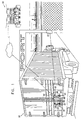
- Fig. 3 is a sectional illustration taken along lines III - III of Fig. 2 ;
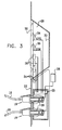
- Fig. 4 is a simplified illustration showing an alternative embodiment of sealing engagement of a door lock handle of a shipping container of the type illustrated in Fig. 1 ;
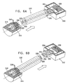
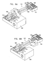
- Figs. 5A and 5B are simplified pictorial illustrations of two stages in the assembly of a press-fit electronic seal particularly useful as a tamper resistant remotely monitorable electronic seal of the type illustrated in Fig. 4 ;
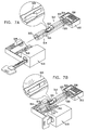
- Figs. 6A and 6B are simplified pictorial illustrations of two different types of breaks produced in the press-fit electronic seal of Figs. 5A and 5B ;
- Figs. 7A and 7B are simplified pictorial illustrations of two stages in the assembly of a lockable electronic seal particularly useful as a tamper resistant remotely monitorable electronic seal of the type illustrated in Fig. 4 ;
- Figs. 8A and 8B are simplified pictorial illustrations of two different types of breaks produced in the lockable electronic seal of Figs. 7A and 7B ;
- Figs. 9A and 9B are simplified pictorial illustrations of two stages in the assembly of a press-fit electronic seal particularly useful as a tamper resistant remotely monitorable electronic seal of the type illustrated in Fig. 4 ;
- Figs. 10A and 10B are simplified pictorial illustrations of two different types of breaks produced in the press-fit electronic seal of Figs. 9A and 9B ;
- Figs. 11A and 11B are simplified pictorial illustrations of two stages in the assembly of a lockable electronic seal particularly useful as a tamper resistant remotely monitorable electronic seal of the type illustrated in Fig. 4 ;
- Figs. 12A and 12B are simplified pictorial illustrations of two different types of breaks produced in the lockable electronic seal of Figs. 11A and 11B .
- a shipping container 10 which may be a conventional shipping container useful for land and sea transport, is shown in communication with multiple communicators, including, for example, a presence sensor and communicator 12, located at the gate of a port, and a remote monitoring center 14, which may communicate via the Internet. It is appreciated that any suitable type of shipping container may be employed.
- the term "shipping container” is used herein in a very broad sense to include any enclosure in which goods may be transported or stored.
- shipping containers employ one or more hasps 15, which are fixed to door latches and are rotatably engageable with corresponding lockable members, such as loops 16, in the manner shown in Figs. 1 and 2 .
- a padlock 17 engages a portion of loop 16 which extends through a hasp 15, preventing disengagement of the hasp 15 from the loop 16 and thus preventing unlocking of the door.
- an electronic seal wire 18 is preferably passed through the loop 16 over the hasp 15.
- a preferred electronic seal wire is described and claimed in applicant/assignee's U.S. Patent No. 6,069,563 , the description of which is hereby incorporated by reference.
- first and second plugs 19, electrically communicating with respective first and second ends of the electronic seal wire 18, are removably received in respective sockets 20, which are recessed behind a wall 22 of a container door.
- the sockets 20 communicate with electronic circuitry 23, which in turn communicates via conductors 24 with RF antennas 26 which are located within an enclosure 28 defined by an outer wall 30 of the container, typically formed of steel, and a cover 32, preferably formed of plastic or other dielectric material, which does not appreciably attenuate the output of the RF antennas 26.
- transceivers forming part of circuitry 23 are employed for receiving and transmitting information relating to the integrity of the seal.
- Each transceiver preferably operates at an RF frequency characteristic of a given part of the world and communicates via corresponding multiple RF antennas 26. Typical transmission frequencies are 315 MHz for the Far East, 433 MHz for Europe and 916 MHz for the U.S.A. Spread spectrum frequencies may also be employed. It is appreciated that alternatively, unidirectional transmitters may be employed instead of transceivers.
- the transceivers preferably communicate with electronic seals mounted on the container as well as with external communicators, such as presence sensor and communicator 12, located at the gate of a port and remote monitoring center 14. Presence sensor and communicator 12 also may communicate with remote monitoring center 14.
- GPS and GSM antennas 34 and 36 and/or any other suitable type of communications antennas may also be located within enclosure 28 and may communicate with circuitry 23 for transmitting data recorded by circuitry 23 to the remote monitoring center 14 via antennas 26 and 36.
- An internal environmental sensor 38 such as one or more sensor which senses carbon dioxide presence, infra-red emissions, temperature and motion may also communicate with circuitry 23. Outputs of sensor 38, which may indicate the presence of contraband within the container may also be transmitted via antennas 26 and 36 for remote monitoring thereof.
- a shipping container 110 which may be a conventional shipping container useful for land and sea transport and which may communicate with multiple communicators, employs one or more hasps 115 which are fixed to door latches and are rotatably engageable with corresponding lockable members, such as loops 116, in the manner shown in Figs. 1 and 2 .
- a tamper resistant remotely monitorable electronic seal 117 is employed instead of the padlock 17 described hereinabove with reference to Figs. 1 & 2 .
- the tamper resistant remotely monitorable electronic seal 117 engages a portion of loop 116 which extends through a hasp 115, preventing disengagement of the hasp from the loop and thus preventing unlocking of the door.
- an electronic seal wire 118 is preferably passed through the loop 116 over the hasp 115.
- a preferred electronic seal wire is described and claimed in applicant/assignee's U.S. Patent No. 6,069,563 , the description of which is hereby incorporated by reference.
- the electronic seal wire 118 is encased in a reinforced steel sleeve 119.
- first and second plugs 120 electrically communicating with respective first and second ends of the electronic seal wire 118 are removably received in respective sockets 121 which are recessed behind a wall 122 of a container door.
- the sockets 121 communicate with electronic circuitry (not shown) such as circuitry 23 ( Fig. 3 ), which in turn communicates with RF antennas which are located within an enclosure 28 ( Fig. 3 ) defined by an outer wall 124 of the container, typically formed of steel, and a cover 125, preferably formed of plastic or other dielectric material, which does not appreciably attenuate the output of the RF transmitting antennas. It is appreciated that the tamper resistant remotely monitorable seal 117 may also communicate directly with presence sensor and communicator 12.
- FIGs. 5A and 5B are simplified pictorial illustrations of two stages in the assembly of a press-fit electronic seal particularly useful as tamper resistant remotely monitorable electronic seal 117 in the embodiment of Fig. 4 .
- a tamper-resistant electronic seal which preferably comprises a shaft portion 210, which is integrally formed with or fixed to a sensing circuitry and transceiver portion 212.
- Shaft portion 210 preferably has a generally cylindrical configuration and terminates in a press-fit tip 214, preferably formed with a series of circumferential teeth 216 which are adapted for press-fit engagement with corresponding tooth-like recesses formed in a socket 218.
- the press-fit engagement between tip 214 of shaft portion 210 and socket 218 is preferably such that it is impossible to remove the tip 214 from the socket 218 without breaking the shaft portion 210.
- Shaft portion 210 preferably includes a weakened frangible portion 220, located intermediate the sensing circuitry and transceiver portion 212 and the tip 214.
- Frangible portion 220 is preferably located closer to sensing circuitry and transceiver portion 212 than to tip 214 and typically has a lesser thickness than the remainder of the shaft portion 210.
- a conductive loop 222 preferably extends through shaft portion 210 through to the tip 214 thereof and is configured and mounted in shaft portion 210, such that breakage of the shaft portion 210 produces a disconnection or significant change in the electrical properties of the conductive loop 222.
- sensing circuitry 224 and an RF transceiver 226 are housed within sensing circuitry and transceiver portion 212.
- Sensing circuitry 224 is electrically coupled to conductive loop 222 and senses the integrity thereof.
- Receiving an output from sensing circuitry 224 is transceiver 226, which is operative to provide transmitted information indicating whether the conductive loop 222 is intact.
- Conventional wireless monitoring circuitry may be employed to receive information which is transmitted by RF transceiver 226 and indicates tampering with the seal which results in breakage of the shaft portion 210.
- Figs. 6A and 6B are simplified pictorial illustrations of two different types of breaks produced in the press-fit electronic seal of Figs. 5A and 5B .
- application of force to the seal of Figs. 6A and 6B in an attempt to separate shaft portion 210 from socket 218 will not cause tip 214 to be disengaged from socket 218, without first breaking the shaft portion 210.
- Fig. 6A shows such a break at a location along the shaft portion 210 which lies just above the tip 214. It is seen that this break produces a disconnection or significant change in the electrical properties of the conductive loop 222.
- Fig. 6B shows such a break at the frangible portion 220 along the shaft portion 210. It is seen that this break also produces a disconnection or significant change in the electrical properties of the conductive loop 222.
- Figs. 7A and 7B are simplified pictorial illustrations of two stages in the assembly of a lockable electronic seal particularly useful as tamper resistant remotely monitorable electronic seal 117 in the embodiment of Fig. 4 .
- a tamper-resistant reusable lockable electronic seal which preferably comprises a shaft portion 310, which is integrally formed with or fixed to a sensing circuitry and transceiver portion 312.
- Shaft portion 310 preferably has a generally cylindrical configuration and terminates in a lockable tip 314, preferably formed with an undercut groove 315 which is adapted for lockable engagement with a corresponding locking element 316 forming part of a lock 318, defining a socket, which includes a magnet 319.
- Lock 318 is here shown to be a key-operated lock, it being appreciated that any other suitable type of lock may be employed.
- the locking engagement between tip 314 of shaft portion 310 and locking element 316 is preferably such that without first unlocking the lock, it is impossible to remove the tip 314 from engagement with the locking element 316 without breaking the shaft portion 310.
- Shaft portion 310 preferably includes a weakened frangible portion 320, located intermediate the sensing circuitry and transceiver portion 312 and the tip 314.
- Frangible portion 320 is preferably located closer to sensing circuitry and transceiver portion 312 than to tip 314 and typically has a lesser thickness than the remainder of the shaft portion 310.
- sensing circuitry 324 and an RF transceiver 326 are housed within sensing circuitry and transceiver portion 312.
- Sensing circuitry 324 is electrically coupled to conductive loop 322 and senses the integrity thereof.
- Receiving an output from sensing circuitry 324 is transceiver 326, which is operative to provide transmitted information indicating whether the conductive loop 322 is intact.
- Conventional wireless monitoring circuitry may be employed to receive information which is transmitted by RF transceiver 326.
- Figs. 8A and 8B are simplified pictorial illustrations of two different types of breaks produced in the lockable electronic seal of Figs. 7A and 7B .
- application of force to the seal of Figs. 8A and 8B in an attempt to separate shaft portion 310 from locking element 316 will not cause tip 314 to be disengaged from locking element 316, without first breaking the shaft portion 310.
- Fig. 8A shows such a break at a location along the shaft portion 310 which lies just above the tip 314. It is seen that this break produces a disconnection or significant change in the electrical properties of the conductive loop 322.
- Fig. 8B shows such a break at the frangible portion 320 along the shaft portion 310. It is seen that this break also produces a disconnection or significant change in the electrical properties of the conductive loop 322.
- Figs. 9A and 9B are simplified pictorial illustrations of two stages in the assembly of a press-fit electronic seal particularly useful as tamper resistant remotely monitorable electronic seal 117 in the embodiment of Fig. 4 .
- a tamper-resistant electronic seal which preferably comprises a shaft portion 410, which is integrally formed with or fixed to a sensing circuitry and transceiver portion 412.
- Shaft portion 410 preferably has a generally cylindrical configuration and terminates in a press-fit tip 414, preferably formed with a series of circumferential teeth 416 which are adapted for press-fit engagement with corresponding tooth-like recesses formed in a socket 418.
- the press-fit engagement between tip 414 of shaft portion 410 and socket 418 is preferably such that it is impossible to remove the tip 414 from the socket 418 without breaking the shaft portion 410.
- Shaft portion 410 preferably includes a weakened frangible portion 420, located intermediate the sensing circuitry and transceiver portion 412 and the tip 414.
- Frangible portion 420 is preferably located closer to sensing circuitry and transceiver portion 412 than to tip 414 and typically has a lesser thickness than the remainder of the shaft portion 410.
- a pair of elongate conductors 422 and 424 preferably extends through shaft portion 410 through to the tip 414 thereof and is configured and mounted in shaft portion 410, such that breakage of the shaft portion 410 produces a disconnection or significant change in the electrical properties of at least one and preferably both of conductors 422 and 424.
- conductors 422 and 424 communicate with respective contacts 426 and 428 which are exposed at the end of tip 414 and are arranged to electrically engage an electrical shorting contact 430 at the corresponding interior surface of socket 418 when shaft portion 410 is fully press-fit mounted into socket 418, thereby defining a conductive loop.
- sensing circuitry 432 and an RF transceiver 434 are housed within sensing circuitry and transceiver portion 412.
- Sensing circuitry 432 is electrically coupled to conductors 422 and 424 and senses the integrity of a conductive loop which is defined by conductors 422 and 424 when the shaft portion 410 is fully seated in socket 418.
- Receiving an output from sensing circuitry 432 is transceiver 434, which is operative to provide transmitted information indicating whether the conductive loop is intact.
- Conventional wireless monitoring circuitry (not shown) may be employed to receive information which is transmitted by RF transceiver 434 and indicates tampering with the seal which results in breakage of the shaft portion 410.
- Figs. 10A and 10B are simplified pictorial illustrations of two different types of breaks produced in the press-fit electronic seal of Figs. 9A and 9B .
- Fig. 10A shows such a break at a location along the shaft portion 410 which lies just above the tip 414. It is seen that this break produces a disconnection or significant change in the electrical properties of the conductive loop defined by conductors 422 and 424.
- Fig. 10B shows such a break at the frangible portion 420 along the shaft portion 410. It is seen that this break also produces a disconnection or significant change in the electrical properties of the conductive loop.
- FIGs. 11A and 11B are simplified pictorial illustrations of two stages in the assembly of a lockable electronic seal particularly useful as tamper resistant remotely monitorable electronic seal 117 in the embodiment of Fig. 4 .
- a tamper-resistant lockable electronic seal which preferably comprises a shaft portion 510, which is integrally formed with or fixed to a sensing circuitry and transceiver portion 512.
- Shaft portion 510 preferably has a generally cylindrical configuration and terminates in a lockable tip 514, preferably formed with an undercut groove 515 which is adapted for lockable engagement with a corresponding locking element 516 forming part of a lock 518, defining a socket, which includes a magnet 519.
- Lock 518 is here shown to be a key-operated lock, it being appreciated that any other suitable type of lock may be employed.
- the locking engagement between tip 514 of shaft portion 510 and locking element 516 is preferably such that without first unlocking the lock, it is impossible to remove the tip 514 from engagement with the locking element 516 without breaking the shaft portion 510.
- Shaft portion 510 preferably includes a weakened frangible portion 520, located intermediate the sensing circuitry and transceiver portion 512 and the tip 514.
- Frangible portion 520 is preferably located closer to sensing circuitry and transceiver portion 512 than to tip 514 and typically has a lesser thickness than the remainder of the shaft portion 510.
- a pair of elongate conductors 522 and 524 extends through shaft portion 510 through to the tip 514 thereof and is configured and mounted in shaft portion 510, such that breakage of the shaft portion 510 produces a disconnection or significant change in the electrical properties of at least one and preferably both of conductors 522 and 524.
- conductors 522 and 524 communicate with respective contacts 526 and 528 which are exposed at the end of tip 514.
- Contacts 526 and 528 are arranged to electrically engage an electrical shorting contact 530 at the corresponding interior surface of lock 518 when shaft portion 510 is in lockable engagement with lock 518. This electrical engagement, together with the closing of series connected reed switch 525 by magnet 519, thereby defines a conductive loop.
- sensing circuitry 532 and an RF transceiver 534 are housed within sensing circuitry and transceiver portion 512.
- Sensing circuitry 532 is electrically coupled to conductors 522 and 524 and senses the integrity of a conductive loop which is defined by conductors 522 and 524 when the shaft portion 510 is in lockable engagement with lock 518.
- Receiving an output from sensing circuitry 532 is transceiver 534, which is operative to provide transmitted information indicating whether the conductive loop is intact.
- Conventional wireless monitoring circuitry may be employed to receive information which is transmitted by RF transceiver 534 and indicates when the shaft portion 510 is located in lockable engagement with lock 518 and when the shaft portion 510 is separated from lock 518 due to either tampering with the seal, which results in breakage of the shaft portion 510, or disengagement of shaft portion 510 and lock 518 by using a key to unlock lock 518.
- reed switch 525 and magnet 519 enables sensing circuitry 532 to sense when the shaft portion 510 is located in lockable engagement with lock 518 and also enables sensing circuitry 532 to sense when the shaft portion 510 is separated from lock 518 for any reason, and allows for recording of engagements and disengagements of shaft portion 510 and lock 518.
- Figs. 12A and 12B are simplified pictorial illustrations of two different types of breaks produced in the lockable electronic seal of Figs. 11A and 11B .
- application of force to the seal of Figs. 12A and 12B in an attempt to separate shaft portion 510 from locking element 516 will not cause tip 514 to be disengaged from locking element 516, without first breaking the shaft portion 510.
- Fig. 12A shows such a break at a location along the shaft portion 510 which lies just above the tip 514. It is seen that this break produces a disconnection or significant change in the electrical properties of the conductive loop defined by conductors 522 and 524.
- Fig. 12B shows such a break at the frangible portion 520 along the shaft portion 510. It is seen that this break also produces a disconnection or significant change in the electrical properties of the conductive loop defined by conductors 522 and 524.
Landscapes
- Physics & Mathematics (AREA)
- General Physics & Mathematics (AREA)
- Engineering & Computer Science (AREA)
- General Health & Medical Sciences (AREA)
- Child & Adolescent Psychology (AREA)
- Microelectronics & Electronic Packaging (AREA)
- Health & Medical Sciences (AREA)
- Emergency Management (AREA)
- Business, Economics & Management (AREA)
- Theoretical Computer Science (AREA)
- Computer Hardware Design (AREA)
- Computer Networks & Wireless Communication (AREA)
- Radar, Positioning & Navigation (AREA)
- Closures For Containers (AREA)
- Lock And Its Accessories (AREA)
- Burglar Alarm Systems (AREA)
- Alarm Systems (AREA)
- Arrangements For Transmission Of Measured Signals (AREA)
Claims (22)
- Ein fernüberwachbarer Container (10) beinhaltet:einen Containerbehälter mit mindestens einer Tür und mindestens einem Türriegel, der über ein Türriegelverschlusselement (16) verfügt, das zur Verschlusssicherung mit einem an der Tür angebrachten Verschlusselement (15) versehen ist;mindestens einen kabellosen Zeichengeber (20), der dazu dient, Informationen hinsichtlich des Status eines auf das Verschlusselement (16) aufgebrachten elektronischen Siegels (18) zur Bestätigung des Verschlusses mindestens einer Tür zu übertragen; sowiemindestens eine kabellose Antenne (26), die außen am Container (10) angebracht ist, um die Informationen von dem mindestens einen kabellosen Zeichengeber (20) zu übertragen,dadurch gekenntzeichnet, dassbesagte mindestens eine kabellose Antenne (26) innerhalb einer Schutzumkleidung (28) am Äußeren des Containers angebracht ist und dass mindestens ein Teil (32) der besagten Schutzumkleidung (28) aus einem Material gefertigt wurde, das die Leistung der mindestens einen besagten kabellosen Antenne (26) nicht nennenswert beeinträchtigt.
- Ein fernüberwachbarer Container (10) gemäß Anspruch 1 und darunter der mindestens eine kabellose Zeichengeber (20) enthalten einen Sendeempfänger.
- Ein fernüberwachbarer Container (10) gemäß Anspruch 2 mit mindestens einer GPS-Antenne (34) zum Empfang von Signalen in Bezug auf den Standort des Containers (10) und einem Standortberichtsschaltkreis, der die Ausgabe von der mindestens einen GPS-Antenne (34) zur Bereitstellung von Informationen an mindestens einen kabellosen Zeichengeber (20) aufnimmt und den Standort des Containers (10) anzeigt.
- Ein fernüberwachbarer Container (10) gemäß Anspruch 2 und darin mindestens ein kabelloser Zeichengeber (20) enthalten mindestens einen Hochfrequenzsender.
- Ein fernüberwachbarer Container (10) gemäß Anspruch 2 und darin mindestens ein kabelloser Zeichengeber (20) enthalten mindestens einen Langstreckensender.
- Ein fernüberwachbarer Container (10) gemäß Anspruch 2 und darin mindestens ein kabelloser Zeichengeber (20) enthalten einen Sender, der über mindestens ein Mobilfunk-, Rundfunk- oder Satelliten-Kommunikationsnetzwerk kommuniziert.
- Ein fernüberwachbarer Container (10) gemäß Anspruch 1 und darin das Türriegelverschlusselement (16), welches ein manipulationssicheres, fernüberwachbares elektronisches Siegel (18) enthält, bestehend aus:einem Schaftteil (19);einer Fassung (20) zur Aufnahme des Schaftteils (19) mit Überwachungsmöglichkeit, wobei die Entkopplung von Kupplung (20) und Schaftteil (19) zu einem überwachbaren Ereignis führt; sowieeinem kabellosen Zeichengeber (20) in Verbindung mit mindestens einem der Schaftteile (19) und der Kupplung (20), der eine fernüberwachbare Anzeige des betreffenden überwachbaren Ereignisses abgibt.
- Ein fernüberwachbarer Container (10) gemäß Anspruch 7 und darin mindestens eine GPS-Antenne (34) zum Erhalt von Signalen in Bezug auf den Standort des Containers (10) und ein Standortberichtsschaltkreis (23), der die Ausgabe von mindestens der einen GPS-Antenne (34) zur Bereitstellung von Informationen an den mindestens einen kabellosen Zeichengeber (20) aufnimmt, der den Standort des Containers (10) anzeigt.
- Ein fernüberwachbarer Container (10) gemäß Anspruch 7 und darin mindestens ein kabelloser Zeichengeber (20) enthalten mindestens einen Hochfrequenzsender.
- Ein femüberwachbarer Container (10) gemäß Anspruch 7 und darin mindestens ein kabelloser Zeichengeber (20) enthalten mindestens einen Langstreckensender.
- Ein fernüberwachbarer Container (10) gemäß Anspruch 1 enthält mindestens einen Sensor (38), der mindestens einen Zustand innerhalb des Containers (10) abtastet. In ihm befinden sich mindestens ein kabelloser Zeichengeber (20) sowie mindestens eine kabellose Antenne (26) zur kabellosen Übertragung von Informationen hinsichtlich einer Abtastung von mindestens einem Sensor (38) an den entfernt liegenden Monitor (14).
- Ein fernüberwachbarer Container (10) gemäß Anspruch 11 und darin mindestens ein Sensor (38), der mindestens einen Kohlendioxidwert sowie Infrarotemissionen und die Temperatur misst.
- Ein fernüberwachbarer Container (10) gemäß Anspruch 11 und darin mindestens ein kabelloser Zeichengeber (20) übertragen außerdem Informationen zum Frachtstatus innerhalb des besagten Containerbehälters.
- Ein fernüberwachbarer Container (10) gemäß Anspruch 1 und darin mindestens eine GPS-Antenne (34) zum Erhalt von Signalen in Bezug auf den Standort des Containers (10) und ein Standortberichtsschaltkreis (23), der die Ausgabe von mindestens einer GPS-Antenne (34) zur Bereitstellung von Informationen an mindestens einen kabellosen Zeichengeber (20) aufnimmt, der den Standort des Containers (10) anzeigt.
- Ein fernüberwachbarer Container (10) gemäß Anspruch 1 und darin mindestens ein kabelloser Zeichengeber (20) enthalten mindestens einen Hochfrequenzsender.
- Ein fernüberwachbarer Container (10) gemäß Anspruch 1 und darin mindestens ein kabelloser Zeichengeber (20) enthalten mindestens einen Langstreckensender.
- Ein fernüberwachbarer Container (10) gemäß Anspruch 1 und darin mindestens ein kabelloser Zeichengeber (20) enthalten einen Sender, der über mindestens ein Mobilfunk-, Rundfunk- oder Satelliten-Kommunikationsnetzwerk kommuniziert.
- Ein Container-Kommunikationssystem enthält:einen fernüberwachbaren Container (10) gemäß allen Ansprüchen 1 bis 17 sowiemindestens einen Fernzeichengeber (14), der mit mindestens einem kabellosen Zeichengeber (20) kommuniziert.
- Ein Container-Kommunikationssystem gemäß Anspruch 18 und darin mindestens ein Fernzeichengeber (14) umfassen mindestens jeweils:einen Präsenzsensor (38) und Zeichengeber (20);einen entfernt liegenden Monitor (14) sowieein elektronisches Siegel (18).
- Ein Container-Kommunikationssystem gemäß Anspruch 18 und darin mindestens ein kabelloser Zeichengeber (20) enthalten mindestens einen Sendeempfänger, der mit mindestens einem Fernzeichengeber (14) kommuniziert, und darin:enthält mindestens ein Fernzeichengeber (14) mindestens jeweils:einen Präsenzsensor (38) und Zeichengeber (20);einen entfernt liegenden Monitor (14) sowieein elektronisches Siegel (18).
- Ein fernüberwachbarer Container (10) gemäß Anspruch 1 enthält mindestens einen Sensor (38), der mindestens den Kohlendioxidausstoß oder die Bewegung innerhalb des Containers (10) abtastet, und darin ist mindestens der eine kabellose Zeichengeber (20) sowie mindestens eine kabellose Antenne (26) enthalten, die kabellos Informationen hinsichtlich einer Ausgabe mindestens eines Sensors (38) an einen entfernt liegenden Monitor (14) übertragen.
- Ein Container-Kommunikationssystem gemäß Anspruch 18 enthält mindestens einen Sensor (38), der mindestens den Kohlendioxidausstoß oder die Bewegung innerhalb des Containers (10) abtastet, und darin ist mindestens der eine kabellose Zeichengeber (20) sowie mindestens eine kabellose Antenne (26) enthalten, die kabellos Informationen hinsichtlich einer Ausgabe mindestens eines Sensors (38) an einen entfernt liegenden Monitor (14) übertragen.
Applications Claiming Priority (3)
| Application Number | Priority Date | Filing Date | Title |
|---|---|---|---|
| US10/228,842 US6753775B2 (en) | 2002-08-27 | 2002-08-27 | Smart container monitoring system |
| US228842 | 2002-08-27 | ||
| PCT/IL2003/000676 WO2004021299A1 (en) | 2002-08-27 | 2003-08-14 | Smart container monitoring system |
Publications (3)
| Publication Number | Publication Date |
|---|---|
| EP1540613A1 EP1540613A1 (de) | 2005-06-15 |
| EP1540613A4 EP1540613A4 (de) | 2010-01-06 |
| EP1540613B1 true EP1540613B1 (de) | 2012-06-06 |
Family
ID=31976124
Family Applications (1)
| Application Number | Title | Priority Date | Filing Date |
|---|---|---|---|
| EP03791154A Expired - Lifetime EP1540613B1 (de) | 2002-08-27 | 2003-08-14 | Intelligentes behälterüberwachungssystem |
Country Status (7)
| Country | Link |
|---|---|
| US (2) | US6753775B2 (de) |
| EP (1) | EP1540613B1 (de) |
| JP (1) | JP2005537569A (de) |
| KR (1) | KR20050067386A (de) |
| CN (1) | CN1692382A (de) |
| AU (1) | AU2003250514A1 (de) |
| WO (1) | WO2004021299A1 (de) |
Families Citing this family (205)
| Publication number | Priority date | Publication date | Assignee | Title |
|---|---|---|---|---|
| US7174769B2 (en) * | 1996-01-23 | 2007-02-13 | Mija Industries, Inc. | Monitoring contents of fluid containers |
| GB2330679B (en) * | 1997-10-21 | 2002-04-24 | 911 Emergency Products Inc | Warning signal light |
| CA2288588A1 (en) * | 1999-05-28 | 2000-11-28 | Doug Miller | System and method for rail transport of trailers |
| US7209468B2 (en) * | 2000-12-22 | 2007-04-24 | Terahop Networks, Inc. | Forming communication cluster of wireless AD HOC network based on common designation |
| US7200132B2 (en) * | 2000-12-22 | 2007-04-03 | Terahop Networks, Inc. | Forming ad hoc RSI networks among transceivers sharing common designation |
| US7391321B2 (en) * | 2005-01-10 | 2008-06-24 | Terahop Networks, Inc. | Keyhole communication device for tracking and monitoring shipping container and contents thereof |
| US7733818B2 (en) * | 2000-12-22 | 2010-06-08 | Terahop Networks, Inc. | Intelligent node communication using network formation messages in a mobile Ad hoc network |
| US7221668B2 (en) * | 2000-12-22 | 2007-05-22 | Terahop Networks, Inc. | Communications within population of wireless transceivers based on common designation |
| US7742772B2 (en) | 2005-10-31 | 2010-06-22 | Terahop Networks, Inc. | Determining relative elevation using GPS and ranging |
| US7783246B2 (en) * | 2005-06-16 | 2010-08-24 | Terahop Networks, Inc. | Tactical GPS denial and denial detection system |
| US8050625B2 (en) | 2000-12-22 | 2011-11-01 | Terahop Networks, Inc. | Wireless reader tags (WRTs) with sensor components in asset monitoring and tracking systems |
| US7539520B2 (en) * | 2005-06-17 | 2009-05-26 | Terahop Networks, Inc. | Remote sensor interface (RSI) having power conservative transceiver for transmitting and receiving wakeup signals |
| US7830850B2 (en) * | 2000-12-22 | 2010-11-09 | Terahop Networks, Inc. | Class-switching in class-based data communcations network |
| US7574168B2 (en) | 2005-06-16 | 2009-08-11 | Terahop Networks, Inc. | Selective GPS denial system |
| US7430437B2 (en) * | 2000-12-22 | 2008-09-30 | Terahop Networks, Inc. | Transmitting sensor-acquired data using step-power filtering |
| US7542849B2 (en) * | 2005-06-03 | 2009-06-02 | Terahop Networks, Inc. | Network aided terrestrial triangulation using stars (NATTS) |
| US7554442B2 (en) | 2005-06-17 | 2009-06-30 | Terahop Networks, Inc. | Event-driven mobile hazmat monitoring |
| US7155264B2 (en) * | 2000-12-22 | 2006-12-26 | Terahop Networks, Inc. | Systems and methods having LPRF device wake up using wireless tag |
| US7526381B2 (en) | 2005-06-03 | 2009-04-28 | Terahop Networks, Inc. | Network aided terrestrial triangulation using stars (NATTS) |
| US20080303897A1 (en) * | 2000-12-22 | 2008-12-11 | Terahop Networks, Inc. | Visually capturing and monitoring contents and events of cargo container |
| US7209771B2 (en) * | 2000-12-22 | 2007-04-24 | Terahop Networks, Inc. | Battery powered wireless transceiver having LPRF component and second wake up receiver |
| US6934540B2 (en) * | 2000-12-22 | 2005-08-23 | Seekernet, Inc. | Network formation in asset-tracking system based on asset class |
| US7574300B2 (en) * | 2005-06-16 | 2009-08-11 | Terahop Networks, Inc. | GPS denial device detection and location system |
| US7563991B2 (en) * | 2005-06-08 | 2009-07-21 | Terahop Networks, Inc. | All weather housing assembly for electronic components |
| US7830273B2 (en) * | 2005-08-18 | 2010-11-09 | Terahop Networks, Inc. | Sensor networks for pipeline monitoring |
| US7133704B2 (en) * | 2000-12-22 | 2006-11-07 | Terahop Networks, Inc. | Manufacture of LPRF device wake up using wireless tag |
| US7705747B2 (en) | 2005-08-18 | 2010-04-27 | Terahop Networks, Inc. | Sensor networks for monitoring pipelines and power lines |
| US7583769B2 (en) | 2005-06-16 | 2009-09-01 | Terahop Netowrks, Inc. | Operating GPS receivers in GPS-adverse environment |
| US7522568B2 (en) * | 2000-12-22 | 2009-04-21 | Terahop Networks, Inc. | Propagating ad hoc wireless networks based on common designation and routine |
| US20090016308A1 (en) * | 2000-12-22 | 2009-01-15 | Terahop Networks, Inc. | Antenna in cargo container monitoring and security system |
| US8280345B2 (en) | 2000-12-22 | 2012-10-02 | Google Inc. | LPRF device wake up using wireless tag |
| EP1246094A1 (de) * | 2001-03-27 | 2002-10-02 | TELEFONAKTIEBOLAGET L M ERICSSON (publ) | System und Verfahren zum Überwachen von Behältern |
| US7961094B2 (en) * | 2002-06-11 | 2011-06-14 | Intelligent Technologies International, Inc. | Perimeter monitoring techniques |
| US8354927B2 (en) | 2002-06-11 | 2013-01-15 | Intelligent Technologies International, Inc. | Shipping container monitoring based on door status |
| US7109847B1 (en) * | 2002-07-18 | 2006-09-19 | Hill James W | Closure security seal with time-recording feature |
| US6753775B2 (en) * | 2002-08-27 | 2004-06-22 | Hi-G-Tek Ltd. | Smart container monitoring system |
| US6778083B2 (en) * | 2002-08-27 | 2004-08-17 | Hi-G-Tek Ltd. | Electronic locking seal |
| US7411495B2 (en) * | 2002-08-27 | 2008-08-12 | Hi-G-Tek Ltd. | Smart container monitoring system |
| US7002472B2 (en) * | 2002-09-04 | 2006-02-21 | Northrop Grumman Corporation | Smart and secure container |
| US7479877B2 (en) * | 2002-09-17 | 2009-01-20 | Commerceguard Ab | Method and system for utilizing multiple sensors for monitoring container security, contents and condition |
| KR101012977B1 (ko) * | 2002-09-17 | 2011-02-10 | 커머스가드 에이비 | 컨테이너의 보안을 유지하기 위해 컨테이너를 모니터링하기위한 시스템 및 방법 |
| US7042354B2 (en) * | 2002-12-11 | 2006-05-09 | Hi-G-Tek Ltd. | Tamper-resistant electronic seal |
| US20040183673A1 (en) * | 2003-01-31 | 2004-09-23 | Nageli Hans Peter | Portable detachable self-contained tracking unit for two-way satellite communication with a central server |
| US7323981B2 (en) * | 2003-02-20 | 2008-01-29 | Global Statistics, Inc. | Container tracking system |
| WO2004077091A1 (en) * | 2003-02-25 | 2004-09-10 | All Set Marine Security Ab | Method and system for monitoring relative movement of maritime containers and other cargo |
| US7259669B2 (en) * | 2003-04-18 | 2007-08-21 | Savi Technology, Inc. | Method and apparatus for detecting unauthorized intrusion into a container |
| US7639134B2 (en) * | 2003-05-07 | 2009-12-29 | Savi Technology, Inc. | Item-level visibility of nested and adjacent containers |
| US20050162269A1 (en) * | 2003-05-07 | 2005-07-28 | Lambright Stephen J. | Dual mode reader device |
| US7068162B2 (en) * | 2003-06-24 | 2006-06-27 | Alan James Maple | Compartment security system |
| ZA200402317B (en) | 2003-09-15 | 2004-10-07 | Andrew Gerald Lynn Brown | "A seal". |
| CN1926589B (zh) * | 2003-10-27 | 2012-01-11 | Savi技术公司 | 集装箱的安全和监视 |
| US7317387B1 (en) | 2003-11-07 | 2008-01-08 | Savi Technology, Inc. | Method and apparatus for increased container security |
| ATE541277T1 (de) * | 2003-11-13 | 2012-01-15 | Commerceguard Ab | Verfahren und system zum überwachen von behältern zur aufrechterhaltung ihrer sicherheit |
| US7265668B1 (en) * | 2003-12-12 | 2007-09-04 | Skybitz, Inc. | System and method for asset tracking and monitoring |
| US7522046B2 (en) * | 2004-03-17 | 2009-04-21 | Sap Aktiengesellschaft | Document management |
| US7358856B2 (en) * | 2004-03-18 | 2008-04-15 | Savi Technology, Inc. | Two-phase commit synchronizing seal state |
| GB0406376D0 (en) * | 2004-03-22 | 2004-04-21 | Maple Alan J | Lock mechanism |
| JP2007531107A (ja) * | 2004-03-24 | 2007-11-01 | オール セット マリン セキュリティ アーベー | コンテナを監視して、そのセキュリティを維持する方法およびシステム(関連出願のクロスレファレンス)本特許出願は、2004年3月24日出願された同時係属中の暫定特許出願第60/556,106号の全体の開示から優先権を主張するとともに、目的の如何に依らず参照することによってその開示を組み込む。また本特許出願は、参照することにより2003年9月17日出願の米国特許出願第10/667,282号を組み込む。 |
| US7239238B2 (en) * | 2004-03-30 | 2007-07-03 | E. J. Brooks Company | Electronic security seal |
| US8068027B2 (en) * | 2004-03-30 | 2011-11-29 | Hi-G-Tek Ltd. | Monitorable locking assemblies |
| DE602005010407D1 (de) * | 2004-04-07 | 2008-11-27 | All Set Marine Security Ab | Verfahren und systeme zur scharfschaltung einer containersicherheitsvorrichtung ohne verwendung eines elektronischen lesers |
| US7755486B2 (en) * | 2004-05-06 | 2010-07-13 | Savi Technology, Inc. | Expanded compatibility RFID tags |
| US7142107B2 (en) | 2004-05-27 | 2006-11-28 | Lawrence Kates | Wireless sensor unit |
| CN100342107C (zh) * | 2004-06-18 | 2007-10-10 | 上海高智科技发展有限公司 | 带无线定位和监控机构的电子密码锁 |
| US8258950B2 (en) * | 2004-07-15 | 2012-09-04 | Savi Technology, Inc. | Method and apparatus for control or monitoring of a container |
| US20060055603A1 (en) * | 2004-09-10 | 2006-03-16 | Joseph Jesson | Concealed planar antenna |
| US7444946B2 (en) * | 2004-09-14 | 2008-11-04 | Halliburton Energy Services, Inc. | Material management apparatus, systems, and methods |
| DE102004053522A1 (de) * | 2004-10-29 | 2006-08-24 | Deutsches Zentrum für Luft- und Raumfahrt e.V. | Überwachungsvorrichtung für Transportgüter und Verfahren zur Überwachung von Transportgütern |
| US7324921B2 (en) * | 2004-12-28 | 2008-01-29 | Rftrax Inc. | Container inspection system |
| US7327248B2 (en) * | 2004-12-30 | 2008-02-05 | Sap Aktiengesellschaft | Generating electronic seals |
| US7378962B2 (en) * | 2004-12-30 | 2008-05-27 | Sap Aktiengesellschaft | Sensor node management and method for monitoring a seal condition of an enclosure |
| EP1839286A2 (de) | 2005-01-10 | 2007-10-03 | Terahop Networks, Inc. | Schlüssellochkommunikationsvorrichtung zur verfolgung und überwachung von versandverpackungen und deren inhalt |
| US7378958B2 (en) * | 2005-01-10 | 2008-05-27 | Terahop Networks, Inc. | Keyhole communication device for tracking and monitoring shipping container and contents thereof |
| DE102005001582A1 (de) | 2005-01-13 | 2006-07-27 | Robert Bosch Gmbh | Einrichtung und Verfahren zur Registrierung des Öffnens von Verschlüssen von zu sichernden Räumen |
| ZA200706162B (en) * | 2005-01-14 | 2008-10-29 | Henderson Matthew | A transponder bolt seal and a housing for a transponder |
| EP1839287A1 (de) * | 2005-01-14 | 2007-10-03 | Matthew Henderson | Transponder-bolzenversiegelung und gehäuse für einen transponder |
| AU2006206045B2 (en) * | 2005-01-14 | 2011-06-16 | Matthew Henderson | A transponder bolt seal and a housing for a transponder |
| KR100587735B1 (ko) | 2005-04-06 | 2006-06-09 | (주)케이피씨 | 컨테이너 개방 감지장치 및 방법 |
| US7283052B2 (en) | 2005-05-13 | 2007-10-16 | Commerceguard Ab | Method and system for arming a multi-layered security system |
| SE528760C2 (sv) * | 2005-05-18 | 2007-02-13 | Secure Logistics Sweden Ab | Metod och anordning för detektering av intrång i eller manipulation av innehållet i en inneslutning |
| WO2006133151A1 (en) | 2005-06-03 | 2006-12-14 | Terahop Networks, Inc. | Using wake-up receivers for soft hand-off in wireless communications |
| US20070008107A1 (en) * | 2005-06-21 | 2007-01-11 | Savi Technology, Inc. | Method and apparatus for monitoring mobile containers |
| EP1905200A1 (de) | 2005-07-01 | 2008-04-02 | Terahop Networks, Inc. | Nichtdeterministisches und deterministisches netzwerk-routing |
| US7438334B2 (en) * | 2005-07-29 | 2008-10-21 | Terry Daniel J | Bolt-type seal lock |
| US7828342B2 (en) * | 2005-07-29 | 2010-11-09 | Terahop Networks, Inc. | Reusable locking body, of bolt-type seal lock, having open-ended passageway and U-shaped bolt |
| CN100458091C (zh) * | 2005-09-22 | 2009-02-04 | 上海物联软件有限公司 | 电子监管锁 |
| US7339482B2 (en) * | 2005-09-30 | 2008-03-04 | The Boeing Company | Shipping container air-vent cover antenna housing |
| US7649459B2 (en) * | 2005-09-30 | 2010-01-19 | The Boeing Company | Shipping container security unit quick mount device |
| US7847691B2 (en) | 2005-09-30 | 2010-12-07 | The Boeing Company | Shipping container security unit quick mount device |
| US20070085680A1 (en) * | 2005-10-19 | 2007-04-19 | Victor Cohen | Device, system and method for securing cargo items |
| US7538672B2 (en) * | 2005-11-01 | 2009-05-26 | Savi Technology, Inc. | Method and apparatus for capacitive sensing of door position |
| US7808383B2 (en) * | 2005-11-03 | 2010-10-05 | Savi Technology, Inc. | Method and apparatus for monitoring an environmental condition with a tag |
| US20090129306A1 (en) | 2007-02-21 | 2009-05-21 | Terahop Networks, Inc. | Wake-up broadcast including network information in common designation ad hoc wireless networking |
| EP1972159A1 (de) | 2006-01-01 | 2008-09-24 | Terahop Networks, Inc. | Feststellung des vorhandenseins einer hf-kommunikationsvorrichtung |
| GB0601977D0 (en) * | 2006-02-01 | 2006-03-15 | Alpha Asd Ltd | A high security lock & integral seal preventing unauthorised access to both passenger & military aircraft whilst unattended & waiting for next tour ofduty |
| US20070193297A1 (en) * | 2006-02-21 | 2007-08-23 | Healthcare Products International, Inc. | Method and device for the transportation of temperature sensitive materials |
| US7737840B2 (en) * | 2006-04-10 | 2010-06-15 | The Boeing Company | Container security system |
| WO2007124129A2 (en) * | 2006-04-20 | 2007-11-01 | Nve Corporataion | Enclosure tamper detection and protection |
| EP1852565B1 (de) * | 2006-05-02 | 2017-03-15 | 3M Innovative Properties Company | Ein abgedichtetes Gehäuse und eine Kombination einschliesslich das abgedichtete Gehäuse und eine Tür |
| CN101438600B (zh) * | 2006-05-02 | 2012-09-05 | 3M创新有限公司 | 通信机罩监视系统 |
| DE102006025214B3 (de) * | 2006-05-29 | 2007-11-08 | Reel Reinheimer Elektronik Gmbh | Anordnung einer Antenne an einem Container |
| US7543467B2 (en) * | 2006-09-19 | 2009-06-09 | Sheehan Thomas R | Portable lock wirelessly connectable to security system |
| US20080246604A1 (en) * | 2006-10-06 | 2008-10-09 | Mcpherson Wayne | Wireless interface module |
| US7936266B2 (en) * | 2006-10-27 | 2011-05-03 | Maritime Container Security, Inc. | Shipping container seal monitoring device, system and method |
| CN100437663C (zh) * | 2006-11-17 | 2008-11-26 | 上海国际港务(集团)股份有限公司 | 带有集装箱定位和电子封条的集装箱电子标签 |
| US7612671B2 (en) * | 2006-11-29 | 2009-11-03 | Motorola, Inc. | Attachment device, attachment receiving device and system for identifying secured containers |
| US8223680B2 (en) | 2007-02-21 | 2012-07-17 | Google Inc. | Mesh network control using common designation wake-up |
| US8294577B2 (en) | 2007-03-09 | 2012-10-23 | Nve Corporation | Stressed magnetoresistive tamper detection devices |
| US7667597B2 (en) | 2007-03-09 | 2010-02-23 | Savi Technology, Inc. | Method and apparatus using magnetic flux for container security |
| KR100886890B1 (ko) * | 2007-03-20 | 2009-03-06 | (주)케이피씨 | 전자봉인장치 및 그를 이용한 개방감지방법 |
| US20080231438A1 (en) * | 2007-03-23 | 2008-09-25 | Diamond Arrow Communications L.L.C. | Cargo Container Monitoring System |
| US20080231454A1 (en) * | 2007-03-23 | 2008-09-25 | Diamond Arrow Communications L.L.C. | Cargo Container Monitoring Device |
| CH699647B1 (de) * | 2007-05-10 | 2010-04-15 | Cwa Const Sa | Verriegelungsüberwachung. |
| CN101755292A (zh) * | 2007-06-15 | 2010-06-23 | 马修·亨德森 | 应答器插销封条以及用于应答器的壳体 |
| EP2201544A4 (de) * | 2007-08-09 | 2013-04-24 | Hi G Tek Inc | Überwachbare dichtende kabelverriegelung |
| US20090066503A1 (en) * | 2007-09-07 | 2009-03-12 | Lien-Feng Lin | System for monitoring containers with seals |
| US9472125B2 (en) | 2007-10-05 | 2016-10-18 | E.J. Brooks Company | Reusable bolt electronic seal module with GPS/cellular phone communications and tracking system |
| US8319640B2 (en) | 2007-10-19 | 2012-11-27 | N7 Systems, Llc | Method for maintaining a shipping container manifest |
| WO2009074052A1 (fr) * | 2007-11-29 | 2009-06-18 | Lien Feng Lin | Système de surveillance de sceau |
| US8031069B2 (en) * | 2008-01-14 | 2011-10-04 | Oded Yair Cohn | Electronic security seal and system |
| CN101494009A (zh) * | 2008-01-24 | 2009-07-29 | 上海英颁斯物流科技有限公司 | 一种识别容器被开启的装置及其方法 |
| EP2083412A1 (de) * | 2008-01-25 | 2009-07-29 | SmTAG international AG | Überwachungseinrichtung |
| US20090240373A1 (en) * | 2008-03-23 | 2009-09-24 | Brown Rork S | Establishing a use cycle using a container condition |
| KR101044442B1 (ko) * | 2008-04-15 | 2011-06-27 | 동아대학교 산학협력단 | 스위치 센서 기반의 컨테이너 보안 시스템 |
| DE102008019964B4 (de) * | 2008-04-21 | 2013-02-28 | Deutsche Post Ag | Mobiler Frachtbehälter mit induktiver Energieversorgung; Umschlag- und/oder Transporteinrichtung für Frachtbehälter; Behälterlogistiksystem und Verfahren zur Energieversorgung eines Frachtbehälters |
| US7969304B2 (en) * | 2008-04-29 | 2011-06-28 | Berland Kerry S | Secured bag locking and tracking device |
| US8207848B2 (en) * | 2008-05-16 | 2012-06-26 | Google Inc. | Locking system for shipping container including bolt seal and electronic device with arms for receiving bolt seal |
| US8462662B2 (en) | 2008-05-16 | 2013-06-11 | Google Inc. | Updating node presence based on communication pathway |
| WO2009151877A2 (en) * | 2008-05-16 | 2009-12-17 | Terahop Networks, Inc. | Systems and apparatus for securing a container |
| US20100141445A1 (en) * | 2008-12-08 | 2010-06-10 | Savi Networks Inc. | Multi-Mode Commissioning/Decommissioning of Tags for Managing Assets |
| US8391435B2 (en) | 2008-12-25 | 2013-03-05 | Google Inc. | Receiver state estimation in a duty cycled radio |
| US20110204656A1 (en) * | 2009-01-27 | 2011-08-25 | Simon Lai | Electronic Seal |
| US8300551B2 (en) | 2009-01-28 | 2012-10-30 | Google Inc. | Ascertaining presence in wireless networks |
| US8705523B2 (en) | 2009-02-05 | 2014-04-22 | Google Inc. | Conjoined class-based networking |
| US8184006B2 (en) * | 2009-03-20 | 2012-05-22 | Mach 1 Development, Inc. | Shipping container integrity device and system |
| US8207854B2 (en) * | 2009-02-09 | 2012-06-26 | Mach 1 Development, Inc. | Shipping container integrity device and system |
| WO2010151901A1 (en) * | 2009-06-26 | 2010-12-29 | Cubic Corporation | System for operating a container lock |
| US8401146B2 (en) * | 2009-07-13 | 2013-03-19 | R. John Vorhees | Conveyer belt with optically visible and machine-detectable indicators |
| US8456302B2 (en) | 2009-07-14 | 2013-06-04 | Savi Technology, Inc. | Wireless tracking and monitoring electronic seal |
| EP2454729A1 (de) | 2009-07-14 | 2012-05-23 | Deal Magic, Inc. | Sicherheitsdichtung |
| US20120261476A1 (en) * | 2009-07-24 | 2012-10-18 | Visibility Solutions Pty Ltd | Wirelessly detectable tamper evident seal |
| US8432274B2 (en) | 2009-07-31 | 2013-04-30 | Deal Magic, Inc. | Contextual based determination of accuracy of position fixes |
| KR20120099631A (ko) | 2009-08-17 | 2012-09-11 | 사비 테크날러지 인코퍼레이티드 | 자산의 상황 인식 모니터링 |
| US8334773B2 (en) * | 2009-08-28 | 2012-12-18 | Deal Magic, Inc. | Asset monitoring and tracking system |
| US8314704B2 (en) * | 2009-08-28 | 2012-11-20 | Deal Magic, Inc. | Asset tracking using alternative sources of position fix data |
| CN102044103B (zh) * | 2009-10-15 | 2012-07-18 | 香港理工大学 | 一种基于rfid电子封条的集装箱管理系统和方法 |
| WO2011074020A1 (en) * | 2009-12-17 | 2011-06-23 | Dsi Sas | Electronic safety seal and process for manufacturing the same |
| EP2372677B1 (de) * | 2010-03-29 | 2016-06-01 | Deutsche Post AG | Versiegelungssystem zum Versiegeln von Türen von Transportfahrzeugen mit türspezifischen Siegeln |
| US8564410B2 (en) * | 2010-05-20 | 2013-10-22 | Paul Llewellyn Greene | Shipping container security process |
| FR2962585B1 (fr) * | 2010-07-07 | 2012-09-07 | Dsi | Scelle de securite, organes de positionnement et de maintien pour un tel scelle et procede de fabrication de tels organes |
| EP2603401A1 (de) | 2010-08-13 | 2013-06-19 | Carrier Corporation | Sicherheitssystem mit transportkühlung |
| US9041534B2 (en) * | 2011-01-26 | 2015-05-26 | En-Gauge, Inc. | Fluid container resource management |
| WO2012123961A2 (en) * | 2011-02-21 | 2012-09-20 | Nitin Manjrekar | A multi-part access control means for sealing and tracking |
| US9558468B2 (en) * | 2011-03-16 | 2017-01-31 | Cubic Corporaton | Transportation route management |
| DE102011106202A1 (de) * | 2011-06-07 | 2012-12-13 | Astrium Gmbh | Verfahren und System zur Überwachung der Integrität von Frachtbehältnissen |
| DE102011108855A1 (de) * | 2011-07-28 | 2013-01-31 | Würth Elektronik GmbH & Co. KG | Elektronisches Siegel |
| EP2610816B1 (de) * | 2011-12-28 | 2021-04-21 | Stoneridge Electronics AB | Fahrzeugeinheit mit integrierter Antenne |
| US20130170107A1 (en) * | 2012-01-04 | 2013-07-04 | Doug Dean | Enclosure for Preventing Tampering of Mobile Communication Equipment in Transportation Industry |
| WO2013134731A1 (en) * | 2012-03-09 | 2013-09-12 | Neology Inc. | Tamper evident cargo container seal bolt lock |
| WO2013142104A1 (en) | 2012-03-19 | 2013-09-26 | Neology Inc. | Tamper evident cargo container seal bolt lock |
| WO2013158062A2 (en) * | 2012-04-16 | 2013-10-24 | University Of Manitoba | Reusable electronic seal |
| CA2820573A1 (en) * | 2012-07-06 | 2014-01-06 | Entreprises Mobilock Inc. | Electric locking device for securing goods |
| BE1021441B1 (nl) * | 2012-10-01 | 2015-11-20 | Track4C Nv | Draadloos containervolgsysteem en container omvattende een dergelijk draadloos containervolgsysteem |
| EP2717242A1 (de) * | 2012-10-03 | 2014-04-09 | Oneseal A/S | Eingreifschloss für einen Behälter |
| WO2014053551A1 (en) * | 2012-10-03 | 2014-04-10 | Oneseal Aps | Engagement lock for a container |
| CN102923414A (zh) * | 2012-11-02 | 2013-02-13 | 上海电机学院 | 集装箱防盗监控系统 |
| JP5987211B2 (ja) * | 2012-12-14 | 2016-09-07 | 國家中山科學研究院 | 結合式マルチモジュール型の電子シール |
| US9112790B2 (en) | 2013-06-25 | 2015-08-18 | Google Inc. | Fabric network |
| CN104657769A (zh) * | 2013-11-20 | 2015-05-27 | 北京易寻方达科技有限责任公司 | 一次性防盗电子钢丝封 |
| US20150373487A1 (en) * | 2014-06-23 | 2015-12-24 | Hirschmann Car Communication Inc. | Long life container tracking device and method for detecting tampering with the tracking device |
| RU2579740C1 (ru) * | 2015-04-01 | 2016-04-10 | Акционерное общество "Инженерный Промышленный Концерн "СТРАЖ" | Электронный модуль запорно-пломбировочного устройства (варианты) |
| CN105034917B (zh) * | 2015-07-30 | 2017-09-12 | 苏州玄禾物联网科技有限公司 | 一种基于全封闭渣土车的渣土倾倒智能检测远程控制系统 |
| CN105015448A (zh) * | 2015-07-30 | 2015-11-04 | 苏州宏展信息科技有限公司 | 一种基于全封闭渣土车的渣土倾倒系统 |
| CN105045239A (zh) * | 2015-07-30 | 2015-11-11 | 苏州玄禾物联网科技有限公司 | 一种基于全封闭渣土车的渣土倾倒监控控制系统 |
| CN105151835A (zh) * | 2015-07-30 | 2015-12-16 | 苏州宏展信息科技有限公司 | 一种基于全封闭渣土车的渣土倾倒射频系统 |
| CN105015447A (zh) * | 2015-07-30 | 2015-11-04 | 苏州宏展信息科技有限公司 | 一种基于全封闭渣土车的智能射频渣土倾倒系统 |
| CN105128813A (zh) * | 2015-07-30 | 2015-12-09 | 苏州宏展信息科技有限公司 | 一种基于全封闭渣土车的智能渣土倾倒系统 |
| CN105065098B (zh) * | 2015-08-06 | 2018-01-09 | 中国北方发动机研究所(天津) | 用于远程防控和监测柴油机排放的装置 |
| US10320081B2 (en) * | 2016-07-13 | 2019-06-11 | Blackberry Limited | Container having a slot antenna |
| CN106314999A (zh) * | 2016-08-30 | 2017-01-11 | 科尔沁牛业南阳有限公司 | 一种牛肉冷鲜肉源头追溯系统及方法 |
| US10455200B2 (en) * | 2016-09-26 | 2019-10-22 | 3 Strike, Llc | Storage container with inventory control |
| US12323743B2 (en) | 2016-09-26 | 2025-06-03 | 3 Strike, Llc | Storage room with inventory control |
| US10267061B2 (en) | 2017-04-03 | 2019-04-23 | Joseph Hage | Locking system and method for a movable freight container |
| US11551498B2 (en) | 2018-04-01 | 2023-01-10 | Joseph Hage | Locking system and method for a movable freight container door |
| US10713613B2 (en) | 2017-04-03 | 2020-07-14 | Joseph Hage | Redundant wireless electronic motor vehicle chassis monitoring network |
| US10851562B2 (en) * | 2017-04-28 | 2020-12-01 | The Regents Of The University Of Colorado, A Body Corporate | Passive continuity monitoring device with active features |
| US10679173B2 (en) | 2018-02-19 | 2020-06-09 | Rpmanetworks Holdings | End to end logistic chain tracking and control of shipping containers |
| WO2019204660A1 (en) | 2018-04-19 | 2019-10-24 | Ember Technologies, Inc. | Portable cooler with active temperature control |
| EP3598081A1 (de) * | 2018-07-17 | 2020-01-22 | Packwise GmbH | Vorrichtung zur überwachung eines zustandsparameters eines industriecontainers |
| CN109462817A (zh) * | 2018-12-11 | 2019-03-12 | 哈尔滨工程大学 | 一种基于北斗导航和无线通讯的海运集装箱监控方法 |
| WO2020146394A2 (en) | 2019-01-11 | 2020-07-16 | Ember Technologies, Inc. | Portable cooler with active temperature control |
| WO2020206486A1 (en) * | 2019-04-09 | 2020-10-15 | Falcon Lair Pty. Ltd. | Electronic bolt seal assembly for cargo containers |
| US11162716B2 (en) | 2019-06-25 | 2021-11-02 | Ember Technologies, Inc. | Portable cooler |
| US11668508B2 (en) | 2019-06-25 | 2023-06-06 | Ember Technologies, Inc. | Portable cooler |
| AU2020304631A1 (en) | 2019-06-25 | 2022-01-06 | Yeti Coolers, Llc | Portable cooler |
| CN110379041A (zh) * | 2019-07-18 | 2019-10-25 | 亳州职业技术学院 | 一种基于车辆位置的运输状态智能自动识别方法 |
| CA3178289A1 (en) | 2020-04-03 | 2021-10-07 | Clayton Alexander | Portable cooler with active temperature control |
| EP4143404A1 (de) | 2020-04-30 | 2023-03-08 | Autida AB | Verriegelungserkennungsvorrichtung |
| US11667165B1 (en) * | 2020-09-29 | 2023-06-06 | Orbcomm Inc. | System, method and apparatus for multi-zone container monitoring |
| BR102021004997B1 (pt) * | 2021-03-16 | 2023-11-07 | Lohmm Participacoes S.A. | Conjunto de containers de carga |
| US11847940B2 (en) * | 2021-04-23 | 2023-12-19 | J. J. Keller & Associates, Inc. | Bolt seal |
| US20220410838A1 (en) * | 2021-06-25 | 2022-12-29 | Heil Trailer International, Llc | Theft-deterrent system for container vehicle |
| US11785424B1 (en) | 2021-06-28 | 2023-10-10 | Wm Intellectual Property Holdings, L.L.C. | System and method for asset tracking for waste and recycling containers |
| EP4494120A1 (de) | 2022-03-16 | 2025-01-22 | Overhaul Group, Inc. | Sendungsverfolgungssystem mit überwachung des zugangs zu einem geschlossenen versandbehälter oder frachtraum |
| US12356292B1 (en) | 2023-07-21 | 2025-07-08 | Wm Intellectual Property Holdings, L.L.C. | Apparatus and method for asset tracking for metal waste and recycling containers |
Family Cites Families (58)
| Publication number | Priority date | Publication date | Assignee | Title |
|---|---|---|---|---|
| US6919803B2 (en) | 2002-06-11 | 2005-07-19 | Intelligent Technologies International Inc. | Low power remote asset monitoring |
| US4750197A (en) | 1986-11-10 | 1988-06-07 | Denekamp Mark L | Integrated cargo security system |
| US4688244A (en) * | 1986-11-10 | 1987-08-18 | Marwan Hannon | Integrated cargo security system |
| US4782784A (en) | 1986-12-15 | 1988-11-08 | Little Cheryl G | Motorized boat-mounted signaling device for water skiers |
| US5097253A (en) | 1989-01-06 | 1992-03-17 | Battelle Memorial Institute | Electronic security device |
| DE4019265C1 (de) | 1990-06-16 | 1991-11-28 | Anatoli 3013 Barsinghausen De Stobbe | |
| US5166929A (en) | 1990-06-18 | 1992-11-24 | Northern Telecom Limited | Multiple access protocol |
| US5056837A (en) | 1990-07-24 | 1991-10-15 | Stoffel Seals Corporation | Tamper resistant shackle seal with assembled locking components |
| US5127687A (en) | 1990-10-17 | 1992-07-07 | E. J. Brooks Co. | Tamper indicator for a locking seal |
| US5266944A (en) | 1991-06-26 | 1993-11-30 | Bodyguard Technologies, Inc. | Electronic system and method for monitoring abusers for compliance with a protective order |
| US5169188A (en) | 1991-08-19 | 1992-12-08 | The United States Of America As Represented By The United States Department Of Energy | Ceramic tamper-revealing seals |
| CH684134A5 (de) | 1991-12-16 | 1994-07-15 | Heinrich Sieber | An einen Gegenstand anbringbarer Sicherungsanhänger zur Signalisierung eines versuchten Diebstahls. |
| US5570080A (en) | 1992-04-24 | 1996-10-29 | Toshio Inoue | Theft prevention tab device having alarm mechanism housed therein |
| US5406263A (en) | 1992-07-27 | 1995-04-11 | Micron Communications, Inc. | Anti-theft method for detecting the unauthorized opening of containers and baggage |
| US5831531A (en) | 1992-07-27 | 1998-11-03 | Micron Communications, Inc. | Anti-theft method for detecting the unauthorized opening of containers and baggage |
| US5587702A (en) | 1992-11-12 | 1996-12-24 | Chadfield; Garth R. | Padlock with tamper alarm |
| US5410301A (en) | 1992-11-24 | 1995-04-25 | Mas-Hamilton Group | Status monitoring system for an electronic lock |
| DE4318441A1 (de) | 1993-06-03 | 1994-12-08 | Sel Alcatel Ag | Notruf-System |
| US5392025A (en) | 1993-09-24 | 1995-02-21 | Intermark Corporation | Electronic security system for display cabinets |
| US5594738A (en) | 1993-10-18 | 1997-01-14 | Motorola, Inc. | Time slot allocation method |
| US5471212A (en) | 1994-04-26 | 1995-11-28 | Texas Instruments Incorporated | Multi-stage transponder wake-up, method and structure |
| US5565858A (en) * | 1994-09-14 | 1996-10-15 | Northrop Grumman Corporation | Electronic inventory system for stacked containers |
| US5615247A (en) * | 1994-10-11 | 1997-03-25 | Mills; Thomas O. | Security device for the protection of cargo transport containers |
| US5525992A (en) | 1994-11-14 | 1996-06-11 | Texas Instruments Deutschland Gmbh | Method and system for conserving power in a recognition system |
| US5615249A (en) | 1994-11-30 | 1997-03-25 | Lucent Technologies Inc. | Service prioritization in a cellular telephone system |
| US5574977A (en) | 1995-04-17 | 1996-11-12 | Telefonaktiebolaget Lm Ericsson | System and method for providing priority access and channel assignment in a cellular telecommunication system |
| US5691980A (en) * | 1995-06-07 | 1997-11-25 | General Electric Company | Local communication network for power reduction and enhanced reliability in a multiple node tracking system |
| US5642355A (en) | 1995-09-29 | 1997-06-24 | Telefonaktiebolaget Lm Ericsson | Method of supporting extended range in a TDMA system |
| US5940006A (en) | 1995-12-12 | 1999-08-17 | Lucent Technologies Inc. | Enhanced uplink modulated backscatter system |
| US6069563A (en) | 1996-03-05 | 2000-05-30 | Kadner; Steven P. | Seal system |
| US5656996A (en) | 1996-03-13 | 1997-08-12 | Global Associates, Ltd. | Electronic security bonding device |
| US5892441A (en) | 1996-06-26 | 1999-04-06 | Par Government Systems Corporation | Sensing with active electronic tags |
| US5910944A (en) | 1997-02-28 | 1999-06-08 | Motorola, Inc. | Radio telephone and method for operating a radiotelephone in slotted paging mode |
| US6288629B1 (en) | 1997-05-23 | 2001-09-11 | Intermec Ip Corp. | Method of using write—ok flag for radio frequency (RF) transponders (RF Tags) |
| US6421540B1 (en) | 1997-05-30 | 2002-07-16 | Qualcomm Incorporated | Method and apparatus for maximizing standby time using a quick paging channel |
| JP3370902B2 (ja) | 1997-06-03 | 2003-01-27 | 株式会社エヌ・ティ・ティ・ドコモ | 移動無線通信におけるハンドオーバ制御方法 |
| US6055426A (en) * | 1997-06-17 | 2000-04-25 | Highwaymaster Communications, Inc. | Notification of a mobile unit out of coverage |
| US6593845B1 (en) | 1998-01-09 | 2003-07-15 | Intermac Ip Corp. | Active RF tag with wake-up circuit to prolong battery life |
| US6133876A (en) | 1998-03-23 | 2000-10-17 | Time Domain Corporation | System and method for position determination by impulse radio |
| US6154139A (en) | 1998-04-21 | 2000-11-28 | Versus Technology | Method and system for locating subjects within a tracking environment |
| US6590886B1 (en) | 1998-07-17 | 2003-07-08 | Qualcomm, Incorporated | Technique for reduction of awake time in a wireless communication device utilizing slotted paging |
| US6256493B1 (en) | 1998-07-31 | 2001-07-03 | Motorola, Inc. | Selective call receiver and method for programming a selective call receiver |
| US6023218A (en) | 1998-08-06 | 2000-02-08 | Tremblay; Steven | Locating and alarm system for a motor vehicle |
| US6366779B1 (en) | 1998-09-22 | 2002-04-02 | Qualcomm Incorporated | Method and apparatus for rapid assignment of a traffic channel in digital cellular communication systems |
| US6297768B1 (en) * | 1999-02-25 | 2001-10-02 | Lunareye, Inc. | Triggerable remote controller |
| US6507567B1 (en) | 1999-04-09 | 2003-01-14 | Telefonaktiebolaget Lm Ericsson (Publ) | Efficient handling of connections in a mobile communications network |
| US6466558B1 (en) | 1999-06-14 | 2002-10-15 | Qualcomm Incorporated | Selection mechanism for signal combining methods |
| US6166627A (en) * | 1999-07-20 | 2000-12-26 | Reeley; Ronald B. | Mobile detection and alert system |
| US6369710B1 (en) | 2000-03-27 | 2002-04-09 | Lucent Technologies Inc. | Wireless security system |
| US6339397B1 (en) * | 2000-06-01 | 2002-01-15 | Lat-Lon, Llc | Portable self-contained tracking unit and GPS tracking system |
| US6646555B1 (en) | 2000-07-18 | 2003-11-11 | Marconi Communications Inc. | Wireless communication device attachment and detachment device and method |
| US6972682B2 (en) | 2002-01-18 | 2005-12-06 | Georgia Tech Research Corporation | Monitoring and tracking of assets by utilizing wireless communications |
| US6879257B2 (en) | 2002-02-25 | 2005-04-12 | Omron Corporation | State surveillance system and method for an object and the adjacent space, and a surveillance system for freight containers |
| US6744366B2 (en) | 2002-04-04 | 2004-06-01 | Hoton How | Method and apparatus of obtaining security tag operation using local magnetic marker |
| AU2003248640A1 (en) | 2002-06-05 | 2003-12-22 | Navitag Technologies, Inc. | Reusable self contained electronic device providing in-transit cargo visibility |
| US6753775B2 (en) * | 2002-08-27 | 2004-06-22 | Hi-G-Tek Ltd. | Smart container monitoring system |
| US6927688B2 (en) | 2003-04-02 | 2005-08-09 | Caci International Inc. | Method for enabling communication and condition monitoring from inside of a sealed shipping container using impulse radio wireless techniques |
| US7098784B2 (en) * | 2003-09-03 | 2006-08-29 | System Planning Corporation | System and method for providing container security |
-
2002
- 2002-08-27 US US10/228,842 patent/US6753775B2/en not_active Expired - Lifetime
-
2003
- 2003-08-14 KR KR1020057003242A patent/KR20050067386A/ko not_active Ceased
- 2003-08-14 WO PCT/IL2003/000676 patent/WO2004021299A1/en not_active Ceased
- 2003-08-14 EP EP03791154A patent/EP1540613B1/de not_active Expired - Lifetime
- 2003-08-14 CN CNA038246090A patent/CN1692382A/zh active Pending
- 2003-08-14 US US10/526,318 patent/US7375619B2/en not_active Expired - Fee Related
- 2003-08-14 JP JP2004532636A patent/JP2005537569A/ja active Pending
- 2003-08-14 AU AU2003250514A patent/AU2003250514A1/en not_active Abandoned
Also Published As
| Publication number | Publication date |
|---|---|
| WO2004021299A1 (en) | 2004-03-11 |
| AU2003250514A1 (en) | 2004-03-19 |
| EP1540613A4 (de) | 2010-01-06 |
| US20060103524A1 (en) | 2006-05-18 |
| US7375619B2 (en) | 2008-05-20 |
| US6753775B2 (en) | 2004-06-22 |
| CN1692382A (zh) | 2005-11-02 |
| KR20050067386A (ko) | 2005-07-01 |
| EP1540613A1 (de) | 2005-06-15 |
| US20040041705A1 (en) | 2004-03-04 |
| JP2005537569A (ja) | 2005-12-08 |
Similar Documents
| Publication | Publication Date | Title |
|---|---|---|
| EP1540613B1 (de) | Intelligentes behälterüberwachungssystem | |
| US7916016B2 (en) | Smart container monitoring system | |
| US20200105167A1 (en) | Reusable bolt electronic seal module with gps/cellular phone communications & tracking system | |
| CA2538746C (en) | A seal | |
| US7336170B2 (en) | Tamper-resistant electronic seal | |
| EP2195802B1 (de) | Bolzenartiger sicherheitsverschluss mit wiederverwendbarem elektronikmodul und bolzen | |
| WO2020206486A1 (en) | Electronic bolt seal assembly for cargo containers | |
| HK1121278A (en) | Smart container monitoring system | |
| HK1085041A (en) | Smart container monitoring system | |
| HK1092922B (en) | A seal |
Legal Events
| Date | Code | Title | Description |
|---|---|---|---|
| PUAI | Public reference made under article 153(3) epc to a published international application that has entered the european phase |
Free format text: ORIGINAL CODE: 0009012 |
|
| 17P | Request for examination filed |
Effective date: 20050329 |
|
| AK | Designated contracting states |
Kind code of ref document: A1 Designated state(s): AT BE BG CH CY CZ DE DK EE ES FI FR GB GR HU IE IT LI LU MC NL PT RO SE SI SK TR |
|
| AX | Request for extension of the european patent |
Extension state: AL LT LV MK |
|
| DAX | Request for extension of the european patent (deleted) | ||
| RIN1 | Information on inventor provided before grant (corrected) |
Inventor name: GENIN, ARCADI Inventor name: BLUM, SHMUEL Inventor name: COHEN, RONY Inventor name: SENDER, RAN Inventor name: AUERBACH, MICHA Inventor name: GOLAN, ELI Inventor name: ISENBERG, ALEX |
|
| RAP1 | Party data changed (applicant data changed or rights of an application transferred) |
Owner name: HI-G-TEK INC. |
|
| RIN1 | Information on inventor provided before grant (corrected) |
Inventor name: COHEN, RONY Inventor name: SENDER, RAN Inventor name: AUERBACH, MICHA Inventor name: GOLAN, ELI Inventor name: GENIN, ARCADI Inventor name: ISENBERG, ALEX Inventor name: BLUM, SHMUEL |
|
| A4 | Supplementary search report drawn up and despatched |
Effective date: 20091209 |
|
| 17Q | First examination report despatched |
Effective date: 20110322 |
|
| REG | Reference to a national code |
Ref country code: DE Ref legal event code: R079 Ref document number: 60341189 Country of ref document: DE Free format text: PREVIOUS MAIN CLASS: G08B0001080000 Ipc: E05B0039000000 |
|
| GRAP | Despatch of communication of intention to grant a patent |
Free format text: ORIGINAL CODE: EPIDOSNIGR1 |
|
| RIC1 | Information provided on ipc code assigned before grant |
Ipc: G07C 11/00 20060101ALI20111128BHEP Ipc: E05B 39/00 20060101AFI20111128BHEP |
|
| GRAS | Grant fee paid |
Free format text: ORIGINAL CODE: EPIDOSNIGR3 |
|
| GRAA | (expected) grant |
Free format text: ORIGINAL CODE: 0009210 |
|
| AK | Designated contracting states |
Kind code of ref document: B1 Designated state(s): AT BE BG CH CY CZ DE DK EE ES FI FR GB GR HU IE IT LI LU MC NL PT RO SE SI SK TR |
|
| REG | Reference to a national code |
Ref country code: GB Ref legal event code: FG4D |
|
| REG | Reference to a national code |
Ref country code: AT Ref legal event code: REF Ref document number: 561138 Country of ref document: AT Kind code of ref document: T Effective date: 20120615 Ref country code: CH Ref legal event code: EP |
|
| REG | Reference to a national code |
Ref country code: IE Ref legal event code: FG4D |
|
| REG | Reference to a national code |
Ref country code: DE Ref legal event code: R096 Ref document number: 60341189 Country of ref document: DE Effective date: 20120802 |
|
| REG | Reference to a national code |
Ref country code: NL Ref legal event code: T3 |
|
| PG25 | Lapsed in a contracting state [announced via postgrant information from national office to epo] |
Ref country code: CY Free format text: LAPSE BECAUSE OF FAILURE TO SUBMIT A TRANSLATION OF THE DESCRIPTION OR TO PAY THE FEE WITHIN THE PRESCRIBED TIME-LIMIT Effective date: 20120606 Ref country code: SE Free format text: LAPSE BECAUSE OF FAILURE TO SUBMIT A TRANSLATION OF THE DESCRIPTION OR TO PAY THE FEE WITHIN THE PRESCRIBED TIME-LIMIT Effective date: 20120606 Ref country code: FI Free format text: LAPSE BECAUSE OF FAILURE TO SUBMIT A TRANSLATION OF THE DESCRIPTION OR TO PAY THE FEE WITHIN THE PRESCRIBED TIME-LIMIT Effective date: 20120606 |
|
| REG | Reference to a national code |
Ref country code: AT Ref legal event code: MK05 Ref document number: 561138 Country of ref document: AT Kind code of ref document: T Effective date: 20120606 |
|
| PG25 | Lapsed in a contracting state [announced via postgrant information from national office to epo] |
Ref country code: GR Free format text: LAPSE BECAUSE OF FAILURE TO SUBMIT A TRANSLATION OF THE DESCRIPTION OR TO PAY THE FEE WITHIN THE PRESCRIBED TIME-LIMIT Effective date: 20120907 Ref country code: SI Free format text: LAPSE BECAUSE OF FAILURE TO SUBMIT A TRANSLATION OF THE DESCRIPTION OR TO PAY THE FEE WITHIN THE PRESCRIBED TIME-LIMIT Effective date: 20120606 |
|
| PG25 | Lapsed in a contracting state [announced via postgrant information from national office to epo] |
Ref country code: EE Free format text: LAPSE BECAUSE OF FAILURE TO SUBMIT A TRANSLATION OF THE DESCRIPTION OR TO PAY THE FEE WITHIN THE PRESCRIBED TIME-LIMIT Effective date: 20120606 Ref country code: SK Free format text: LAPSE BECAUSE OF FAILURE TO SUBMIT A TRANSLATION OF THE DESCRIPTION OR TO PAY THE FEE WITHIN THE PRESCRIBED TIME-LIMIT Effective date: 20120606 Ref country code: RO Free format text: LAPSE BECAUSE OF FAILURE TO SUBMIT A TRANSLATION OF THE DESCRIPTION OR TO PAY THE FEE WITHIN THE PRESCRIBED TIME-LIMIT Effective date: 20120606 Ref country code: CZ Free format text: LAPSE BECAUSE OF FAILURE TO SUBMIT A TRANSLATION OF THE DESCRIPTION OR TO PAY THE FEE WITHIN THE PRESCRIBED TIME-LIMIT Effective date: 20120606 Ref country code: BE Free format text: LAPSE BECAUSE OF FAILURE TO SUBMIT A TRANSLATION OF THE DESCRIPTION OR TO PAY THE FEE WITHIN THE PRESCRIBED TIME-LIMIT Effective date: 20120606 Ref country code: AT Free format text: LAPSE BECAUSE OF FAILURE TO SUBMIT A TRANSLATION OF THE DESCRIPTION OR TO PAY THE FEE WITHIN THE PRESCRIBED TIME-LIMIT Effective date: 20120606 |
|
| PG25 | Lapsed in a contracting state [announced via postgrant information from national office to epo] |
Ref country code: PT Free format text: LAPSE BECAUSE OF FAILURE TO SUBMIT A TRANSLATION OF THE DESCRIPTION OR TO PAY THE FEE WITHIN THE PRESCRIBED TIME-LIMIT Effective date: 20121008 Ref country code: IT Free format text: LAPSE BECAUSE OF FAILURE TO SUBMIT A TRANSLATION OF THE DESCRIPTION OR TO PAY THE FEE WITHIN THE PRESCRIBED TIME-LIMIT Effective date: 20120606 |
|
| REG | Reference to a national code |
Ref country code: CH Ref legal event code: PL |
|
| PG25 | Lapsed in a contracting state [announced via postgrant information from national office to epo] |
Ref country code: MC Free format text: LAPSE BECAUSE OF NON-PAYMENT OF DUE FEES Effective date: 20120831 |
|
| PLBE | No opposition filed within time limit |
Free format text: ORIGINAL CODE: 0009261 |
|
| STAA | Information on the status of an ep patent application or granted ep patent |
Free format text: STATUS: NO OPPOSITION FILED WITHIN TIME LIMIT |
|
| PG25 | Lapsed in a contracting state [announced via postgrant information from national office to epo] |
Ref country code: CH Free format text: LAPSE BECAUSE OF NON-PAYMENT OF DUE FEES Effective date: 20120831 Ref country code: LI Free format text: LAPSE BECAUSE OF NON-PAYMENT OF DUE FEES Effective date: 20120831 Ref country code: ES Free format text: LAPSE BECAUSE OF FAILURE TO SUBMIT A TRANSLATION OF THE DESCRIPTION OR TO PAY THE FEE WITHIN THE PRESCRIBED TIME-LIMIT Effective date: 20120917 Ref country code: DK Free format text: LAPSE BECAUSE OF FAILURE TO SUBMIT A TRANSLATION OF THE DESCRIPTION OR TO PAY THE FEE WITHIN THE PRESCRIBED TIME-LIMIT Effective date: 20120606 |
|
| 26N | No opposition filed |
Effective date: 20130307 |
|
| REG | Reference to a national code |
Ref country code: IE Ref legal event code: MM4A |
|
| REG | Reference to a national code |
Ref country code: DE Ref legal event code: R097 Ref document number: 60341189 Country of ref document: DE Effective date: 20130307 |
|
| PG25 | Lapsed in a contracting state [announced via postgrant information from national office to epo] |
Ref country code: IE Free format text: LAPSE BECAUSE OF NON-PAYMENT OF DUE FEES Effective date: 20120814 Ref country code: BG Free format text: LAPSE BECAUSE OF FAILURE TO SUBMIT A TRANSLATION OF THE DESCRIPTION OR TO PAY THE FEE WITHIN THE PRESCRIBED TIME-LIMIT Effective date: 20120906 |
|
| PGFP | Annual fee paid to national office [announced via postgrant information from national office to epo] |
Ref country code: DE Payment date: 20130821 Year of fee payment: 11 |
|
| PGFP | Annual fee paid to national office [announced via postgrant information from national office to epo] |
Ref country code: FR Payment date: 20130823 Year of fee payment: 11 |
|
| PG25 | Lapsed in a contracting state [announced via postgrant information from national office to epo] |
Ref country code: TR Free format text: LAPSE BECAUSE OF FAILURE TO SUBMIT A TRANSLATION OF THE DESCRIPTION OR TO PAY THE FEE WITHIN THE PRESCRIBED TIME-LIMIT Effective date: 20120606 |
|
| PG25 | Lapsed in a contracting state [announced via postgrant information from national office to epo] |
Ref country code: LU Free format text: LAPSE BECAUSE OF NON-PAYMENT OF DUE FEES Effective date: 20120814 |
|
| PG25 | Lapsed in a contracting state [announced via postgrant information from national office to epo] |
Ref country code: HU Free format text: LAPSE BECAUSE OF FAILURE TO SUBMIT A TRANSLATION OF THE DESCRIPTION OR TO PAY THE FEE WITHIN THE PRESCRIBED TIME-LIMIT Effective date: 20030814 |
|
| REG | Reference to a national code |
Ref country code: DE Ref legal event code: R119 Ref document number: 60341189 Country of ref document: DE |
|
| REG | Reference to a national code |
Ref country code: DE Ref legal event code: R119 Ref document number: 60341189 Country of ref document: DE Effective date: 20150303 |
|
| REG | Reference to a national code |
Ref country code: FR Ref legal event code: ST Effective date: 20150430 |
|
| PG25 | Lapsed in a contracting state [announced via postgrant information from national office to epo] |
Ref country code: DE Free format text: LAPSE BECAUSE OF NON-PAYMENT OF DUE FEES Effective date: 20150303 |
|
| PG25 | Lapsed in a contracting state [announced via postgrant information from national office to epo] |
Ref country code: FR Free format text: LAPSE BECAUSE OF NON-PAYMENT OF DUE FEES Effective date: 20140901 |
|
| PGFP | Annual fee paid to national office [announced via postgrant information from national office to epo] |
Ref country code: NL Payment date: 20170821 Year of fee payment: 15 |
|
| PGFP | Annual fee paid to national office [announced via postgrant information from national office to epo] |
Ref country code: GB Payment date: 20170822 Year of fee payment: 15 |
|
| REG | Reference to a national code |
Ref country code: NL Ref legal event code: MM Effective date: 20180901 |
|
| GBPC | Gb: european patent ceased through non-payment of renewal fee |
Effective date: 20180814 |
|
| PG25 | Lapsed in a contracting state [announced via postgrant information from national office to epo] |
Ref country code: NL Free format text: LAPSE BECAUSE OF NON-PAYMENT OF DUE FEES Effective date: 20180901 |
|
| PG25 | Lapsed in a contracting state [announced via postgrant information from national office to epo] |
Ref country code: GB Free format text: LAPSE BECAUSE OF NON-PAYMENT OF DUE FEES Effective date: 20180814 |