EP1540431B1 - Method for regulating the current flowing through an electromagnetic actuator - Google Patents
Method for regulating the current flowing through an electromagnetic actuator Download PDFInfo
- Publication number
- EP1540431B1 EP1540431B1 EP03740069A EP03740069A EP1540431B1 EP 1540431 B1 EP1540431 B1 EP 1540431B1 EP 03740069 A EP03740069 A EP 03740069A EP 03740069 A EP03740069 A EP 03740069A EP 1540431 B1 EP1540431 B1 EP 1540431B1
- Authority
- EP
- European Patent Office
- Prior art keywords
- switch
- current
- actuator
- pwm signal
- value
- Prior art date
- Legal status (The legal status is an assumption and is not a legal conclusion. Google has not performed a legal analysis and makes no representation as to the accuracy of the status listed.)
- Expired - Lifetime
Links
- 238000000034 method Methods 0.000 title claims abstract description 15
- 230000001105 regulatory effect Effects 0.000 title claims abstract description 8
- 230000010355 oscillation Effects 0.000 claims abstract description 6
- 230000006870 function Effects 0.000 claims description 25
- 238000003745 diagnosis Methods 0.000 claims description 15
- 238000012937 correction Methods 0.000 claims description 7
- 238000004590 computer program Methods 0.000 claims description 6
- 230000005540 biological transmission Effects 0.000 claims description 4
- XEEYBQQBJWHFJM-UHFFFAOYSA-N Iron Chemical group [Fe] XEEYBQQBJWHFJM-UHFFFAOYSA-N 0.000 description 6
- 230000008859 change Effects 0.000 description 4
- 230000001276 controlling effect Effects 0.000 description 4
- 230000008901 benefit Effects 0.000 description 3
- 238000010586 diagram Methods 0.000 description 3
- 238000012544 monitoring process Methods 0.000 description 3
- 238000011161 development Methods 0.000 description 2
- 230000004044 response Effects 0.000 description 2
- 238000012935 Averaging Methods 0.000 description 1
- 238000002485 combustion reaction Methods 0.000 description 1
- 150000001875 compounds Chemical class 0.000 description 1
- 230000008878 coupling Effects 0.000 description 1
- 238000010168 coupling process Methods 0.000 description 1
- 238000005859 coupling reaction Methods 0.000 description 1
- 230000001419 dependent effect Effects 0.000 description 1
- 238000009472 formulation Methods 0.000 description 1
- 230000006872 improvement Effects 0.000 description 1
- 238000002347 injection Methods 0.000 description 1
- 239000007924 injection Substances 0.000 description 1
- 230000007257 malfunction Effects 0.000 description 1
- 239000000203 mixture Substances 0.000 description 1
- 230000009467 reduction Effects 0.000 description 1
- 239000000243 solution Substances 0.000 description 1
- 230000003068 static effect Effects 0.000 description 1
- 230000001960 triggered effect Effects 0.000 description 1
Images


Classifications
-
- G—PHYSICS
- G05—CONTROLLING; REGULATING
- G05B—CONTROL OR REGULATING SYSTEMS IN GENERAL; FUNCTIONAL ELEMENTS OF SUCH SYSTEMS; MONITORING OR TESTING ARRANGEMENTS FOR SUCH SYSTEMS OR ELEMENTS
- G05B19/00—Programme-control systems
- G05B19/02—Programme-control systems electric
- G05B19/18—Numerical control [NC], i.e. automatically operating machines, in particular machine tools, e.g. in a manufacturing environment, so as to execute positioning, movement or co-ordinated operations by means of programme data in numerical form
- G05B19/19—Numerical control [NC], i.e. automatically operating machines, in particular machine tools, e.g. in a manufacturing environment, so as to execute positioning, movement or co-ordinated operations by means of programme data in numerical form characterised by positioning or contouring control systems, e.g. to control position from one programmed point to another or to control movement along a programmed continuous path
-
- G—PHYSICS
- G05—CONTROLLING; REGULATING
- G05B—CONTROL OR REGULATING SYSTEMS IN GENERAL; FUNCTIONAL ELEMENTS OF SUCH SYSTEMS; MONITORING OR TESTING ARRANGEMENTS FOR SUCH SYSTEMS OR ELEMENTS
- G05B2219/00—Program-control systems
- G05B2219/30—Nc systems
- G05B2219/41—Servomotor, servo controller till figures
- G05B2219/41156—Injection of vibration anti-stick, against static friction, dither, stiction
-
- G—PHYSICS
- G05—CONTROLLING; REGULATING
- G05B—CONTROL OR REGULATING SYSTEMS IN GENERAL; FUNCTIONAL ELEMENTS OF SUCH SYSTEMS; MONITORING OR TESTING ARRANGEMENTS FOR SUCH SYSTEMS OR ELEMENTS
- G05B2219/00—Program-control systems
- G05B2219/30—Nc systems
- G05B2219/41—Servomotor, servo controller till figures
- G05B2219/41206—Lookup table, memory with certain relationships
-
- G—PHYSICS
- G05—CONTROLLING; REGULATING
- G05B—CONTROL OR REGULATING SYSTEMS IN GENERAL; FUNCTIONAL ELEMENTS OF SUCH SYSTEMS; MONITORING OR TESTING ARRANGEMENTS FOR SUCH SYSTEMS OR ELEMENTS
- G05B2219/00—Program-control systems
- G05B2219/30—Nc systems
- G05B2219/42—Servomotor, servo controller kind till VSS
- G05B2219/42235—Adaptive pulsing, augment time duration until movement detected
Definitions
- PWM pulse width modulation
- a problem of the known control is that the electromagnetic actuator usually has a hysteresis. This leads, for example when using the actuator in a transmission control of a motor vehicle to the fact that exact switching operations of the transmission due to inaccuracies of the regulation resulting from the hysteresis are no longer readily feasible.
- the object of the invention is to provide a method for controlling the current through an electromagnetic actuator, which allows a higher accuracy of the scheme.
- This object is achieved in a method of the type mentioned in the present invention that the time duration of an on and off cycle of the PWM signal is changed, and that the PWM signal is a so-called Dither function is superimposed in the form of a low-frequency oscillation.
- the change in the duration of an on-off cycle represents a change in the so-called chopper frequency of the PWM signal.
- the chopper frequency By thus changing the chopper frequency, it is possible to reduce so-called seat bounce of the electromagnetic actuator. It is also possible to reduce the hysteresis of the actuator, in particular in the middle current range by reducing the chopper frequency.
- the chopper frequency can be selected depending on the temperature, so that the friction hysteresis of the actuator is reduced by lowering the chopper frequency.
- the dither function achieves a further improvement of this control.
- the movable iron core of the actuator is prevented from transitioning to a state of stiction by means of the low-frequency oscillation of the PWM signal. So it can the iron core by the dither function continuously in one Condition of sliding friction held and thus a minimum hysteresis of the actuator can be achieved.
- the time duration during which the dither value is added to the pulses of the PWM signal is preferably equal to the time duration during which the dither value is subtracted from the pulses.
- the two time periods result in a total time duration, which is a multiple of the duration of an on and off cycle of the PWM signal.
- the current measured by the current measuring circuit and flowing through the actuator is freed from a correction by the dither function. It is particularly advantageous if two current values are measured at the time interval of that time duration during which the dither value is added to the pulses of the PWM signal or subtracted, and that an average of these two measured current values is formed.
- the current through the actuator is determined by a diagnosis from the measured on and off times of the first switch, and it is compared by the diagnosis of this determined current with the current measured by the current measuring circuit and / or with the desired value ,
- the invention may also be implemented in the form of a computer program or in the form of a control device.
- the computer program can then be stored on an electronic storage medium.
- the controller may include those components of the invention implemented in software.
- the controller may have all those components that are required for coupling the software with the actuator and the associated hardware components.
- an electromagnetic actuator 10 is shown, which may be, for example, a coil with an iron core arranged displaceably therein.
- the actuator 10 may be used, for example, in a transmission control of a motor vehicle or as an injection valve of an internal combustion engine or the like.
- the actuator 10 is connected via a first switch 11 to a supply voltage UV and a second switch 12 to ground. Between the actuator 10 and the second switch 12, a current measuring circuit 13 is interposed and a monitor 14 is connected. Parallel to the actuator 10 and the current measuring circuit 13, a freewheeling diode 15 is connected.
- a diagnostic circuit 16 is connected at the connection point of the actuator 10 and the first switch 11.
- the connection point of the current measuring circuit 13 and the monitor 14 is connected via a resistor 17 to the supply voltage UV.
- a controller 20 is supplied with the supply voltage UV, with a signal representing the ambient temperature TU and a signal indicative of a setpoint SW.
- a signal generated by the current measuring circuit 13 is processed by a correction 21 to then be passed to the controller 20.
- the controller 20 controls on the one hand via a pulse generator 22 to the first switch 11 and on the other hand directly to the second switch 12.
- a diagnostic 23 is acted upon by signals generated by the diagnostic circuit 16, the current measuring circuit 13 and the monitoring 14. Furthermore, the setpoint SW is still present at the diagnosis 23. Depending on this, the diagnosis 23 can affect the control 20.
- FIG. 1 only a single actuator 10 is shown.
- the illustrated system is adapted to control the flow through this actuator 10.
- a plurality of actuators 10 are present.
- those components are in the FIG. 1 are arranged between the two dashed lines 25, present in a corresponding plurality.
- a plurality of actuators 10 are present in this case, but also a plurality of respectively associated first switches 11, current measuring circuits 13, freewheeling diodes 15 and diagnostic circuits 16.
- the plurality of actuators 10 are then driven in parallel in the same manner as shown in FIG. 1 has been shown and already explained.
- those compounds that are multiple in this case are shown as thicker lines.
- These connections may, for example, be bus connections in which each control valve 10 is assigned a single line of the bus connection.
- the components shown between the two lines 25 are designed as hardware components.
- the in the FIG. 1 to the left of the lines 25 are shown preferably implemented as software and provided for execution by a microprocessor or the like.
- a computer program is provided whose program instructions are adapted to be executed on the microprocessor.
- the computer program is preferably stored on a flash memory, which is housed together with the microprocessor in a control unit. Between the hardware components and the microprocessor or the control unit interfaces, analog / digital converters and the like may be present, which in the FIG. 1 are not shown.
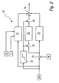
- the regulation 20 of the FIG. 1 is in the FIG. 2 shown in more detail.
- the controller 20 has a pilot control 31, an I-portion 32 and a P-portion 33.
- the pilot control 31 is acted upon by the supply voltage UV, the ambient temperature TU and the setpoint SW. In response, the feedforward control 31 generates a signal which is supplied to an addition point 34.
- the feedforward control 31 has the task of keeping the deviation to be compensated for by the I-component 32 and the F-component 33 as small as possible.
- An actual value IW is subtracted from the setpoint SW at a subtraction point 35.
- the actual value IM corresponds to that signal, which from the correction 21 of FIG. 1 is produced.
- the difference determined by the subtraction point 35 acts on the 1-part 32 and the P-part 33.
- the P-part 33 generates a signal which is supplied to the addition point 34.
- the generation of the I component 32 can be interrupted by means of two switches 36.
- the two switches 36 are driven by a block 37, which in turn is acted upon by the desired value SW.
- the block 37 detects whether the set point SW is making a jump exceeding a predetermined maximum jump. If this is the case, the block 37 opens the two switches 36 and interrupts the generation of the I component 32. The jump of the desired value SW is then compensated solely by the P component 33.
- the duration of the interruption of the 1-part 33 may be fixed or variable selected, for example, depending on the jump height of the setpoint SM.
- the switches 36 remain closed and the I-portion 32 is active. Of the 1 portion 32 is then supplied to the addition point 34. It is again pointed out at this point that the regulation 20 of the FIG. 2 and thus also the switches 36 are preferably realized as software.
- the sum S generated by the addition point 34 corresponds to the signal which is generated by the controller 20 and supplied to the pulse generator 22.
- Such a PWM signal is exemplary in the FIG. 3 applied over time t.
- the PWM signal discriminates only between an on state ("1") in which the first switch 11 is closed and an off state ("0") in which the first switch 11 is opened.
- an on state in which the first switch 11 is closed
- an off state 0
- the first switch 11 is opened.
- a current flows from the voltage supply UV via the first switch 11, the actuator 10, the current measuring circuit 13 and the closed second switch 12 to ground.
- the first switch 11 is open, no such current flows.
- the PWM signal is generated by the pulse generator 22 in response to the output of the controller 20.
- the pulse generator 22 converts the output signal of the controller 20 into a PWM signal whose ratio of the switch-on and switch-off durations corresponds to the magnitude of the output signal.
- the time duration TC of an on and off cycle of the PWM signal corresponds to the so-called chopper frequency of the PWM signal.
- the controller 20 and / or the pulse generator 22 can variably change this time period TC. If a plurality of actuators 10 are present, their time periods TC can be changed independently of one another and variably.
- the change in the durations TC and thus the chopper frequency can also be used to achieve a reduction of the so-called seat bounce of the actuator 10 by a smaller stroke amplitude of the displaceable iron core at a larger chopper frequency. Due to a lower chopper frequency, the hysteresis of the actuator 10 can be reduced, especially in a medium current range.
- the chopper frequency can be set in such a temperature-dependent manner that the chopper frequency is reduced at lower temperatures, so that a friction hysteresis of the actuator 10 which is present at lower temperatures is reduced.
- the controller 20 and / or the pulse generator 22 can perform a so-called dither function, which is a low-frequency oscillation superposition for the current through the actuator 10.
- a specifiable dither value DW is added or subtracted from the PWM signal determined per se.
- This dither function can be performed independently and variably for a plurality of actuators 10.
- the individual pulses of the PWM signal are first extended by the dither value DW and then shortened.
- the time duration T1 in which the individual pulses are extended, is equal to the time period T2, in which the pulses are shortened.
- the total duration TD of the dither function resulting additively from the two aforementioned time periods T1, T2 is a multiple of the time duration TC of the chopper frequency. In the present case, the time TD is ten times the time TC.
- the dither function With the aid of the dither function, it is possible, in particular, to prevent the movable iron core of the actuated actuator 10 from becoming in the state of static friction.
- the iron core can be kept continuously in a state of sliding friction by the dither function and thus a minimum hysteresis of the actuator 10 can be achieved.
- the controller 20 is triggered at predetermined time intervals and executed according to the number of existing actuators 10. It will be available to all Actuators 10 passed corresponding output signal from the controller 20 to the pulse generator 22, which then continuously generates the respective associated PWM signals for the various actuators 10, with which finally to the various actuators 10 respectively associated first switch 11 are controlled.
- the current flowing through the various actuators 10 in this way is measured by the respectively associated current measuring circuit 13.
- the current measuring circuit may preferably be a so-called shunt resistor.
- the measured current value is forwarded to the correction 21, where the dither function introduced by the controller 20 or the pulse generator 22 is eliminated again. This ensures that the dither function has no influence on the control 20.
- the dither function can be compensated in the correction 21, for example, by forming the mean value from two current values measured at the time interval T1. Due to the relationship between the time duration TD of the dither function and the time duration TC of the chopper frequency, the dither function and in particular the dither value DW are no longer contained in the abovementioned mean value.
- the correction 21 passes on the measured current value, which has been freed from the dither function, to the control 20 as actual value IW.
- the measured current value is also passed from the current measuring circuit 13 to the diagnosis 23. There, the measured current value is compared with the setpoint SW. In the case of a deviation which exceeds a predefinable maximum value, the diagnosis 23 can either correctively intervene via the control 20 or switch off the flow through the relevant actuator 10 or even for all the present actuators 10.
- the existing between the / the actuator / ern 10 and the second switch 12 potential is monitored by the monitor 14 and passed to the diagnosis 23. If this potential is faulty, in particular there is a short circuit to the supply voltage UV, then the second switch 12 is immediately opened by the diagnosis 23 via the controller 20, so that no more current can flow via the actuator 10.
- the existing between the / the Stellgliad / ern 10 and the first switch 11 potential is monitored by the diagnostic circuit 16 and passed to the diagnosis 23. If this potential is faulty, lies In particular, a short circuit to ground, so the first switch 11 is opened by the diagnosis 23 via the controller 20 immediately remaining, so that no more current can flow over the / the actuator / he 10.
- the diagnosis circuit 16 recognizes those times when the first switch (s) 11 is opened and closed. From these measured times of the diagnosis 23, the respective current value can be determined, which flows through the associated actuator 10. This determined current value is compared with the current value measured by the current measuring circuit 13 and / or with the desired value SW. If the diagnosis 23 detects a deviation which is greater than a predefined maximum value, the current can again be switched off by the associated actuator 10 or by all existing actuators 10 via the controller 20.
- the second switch 12 Before the first operation of the in the FIG. 1 shown system for controlling the current through the / the actuator / he 10, ie In particular during an initialization of the system, the second switch 12 is still open so that no current flows through the actuator 10. The potential between the / the actuator / ern 10 and the second switch 12 can not be determined per se.
- the resistor 17 is present only once and has a rather large resistance value. Due to the resistor 17, the potential between the / the actuator / ern 10 and the second switch 12 is determined by the monitoring 14 and thus a short circuit to the supply voltage UV or ground can be determined.
- Deviating from the FIG. 1 it is possible that the PWM signal applied to the second switch and the first switch remains continuously closed during normal operation.
- the diagnostic circuit is in this case the second switch and the monitoring associated with the first switch. Otherwise, however, the variable chopper frequency and the dither function are equally applicable, as in the FIG. 1 is described.
Abstract
Description
Die Erfindung geht aus von einem Verfahren zum Regeln des Stroms durch ein elektromagnetisches Stellglied, wobei das Stellglied, ein erster Schalter und eine Strommessschaltung eine Serienschaltung bilden, wobei dem Stellglied (10) eine Freilaufdiode parallelgeschaltet ist, und wobei der erste Schalter von einer Regelung und einer Pulsgenerierung mittels eines PWM-Signals (PWM = Pulsweitenmodulation) derart geschlossen und geöffnet wird, dass der von der Strommessschaltung gemessene, durch das Stellglied fließende Strom auf einen Sollwert geregelt wird.The invention is based on a method for regulating the current through an electromagnetic actuator, wherein the actuator, a first switch and a current measuring circuit form a series circuit, wherein the actuator (10) a freewheeling diode is connected in parallel, and wherein the first switch of a control and a pulse generation by means of a PWM signal (PWM = pulse width modulation) is closed and opened so that the measured by the current measuring circuit, flowing through the actuator current is controlled to a desired value.
Ein derartiges Verfahren ist allgemein bekannt (siehe beispielsweise
Ein Problem der bekannten Regelung besteht darin, dass das elektromagnetische Stellglied üblicherweise eine Hysterese aufweist. Dies führt beispielsweise beim Einsatz des Stellglieds bei einer Getriebesteuerung eines Kraftfahrzeugs dazu, dass exakte Schaltvorgänge des Getriebes aufgrund von aus der Hysterese resultierenden Ungenauigkeiten der Regelung nicht mehr ohne weiteres durchführbar sind.A problem of the known control is that the electromagnetic actuator usually has a hysteresis. This leads, for example when using the actuator in a transmission control of a motor vehicle to the fact that exact switching operations of the transmission due to inaccuracies of the regulation resulting from the hysteresis are no longer readily feasible.
Aufgabe der Erfindung ist es, ein Verfahren zum Regeln des Stroms durch ein elektromagnetisches Stellglied zu schaffen, das eine höhere Genauigkeit der Regelung ermöglicht.The object of the invention is to provide a method for controlling the current through an electromagnetic actuator, which allows a higher accuracy of the scheme.
Diese Aufgabe wird bei einem Verfahren der eingangs genannten Art erfindungsgemäß dadurch gelöst, dass die Zeitdauer eines Ein- und Ausschaltzyklus des PWM-Signals verändert wird, und dass dem PWM-Signal eine sogenannte Ditherfunktion in der Form einer niederfrequenten Schwingung überlagert wird.This object is achieved in a method of the type mentioned in the present invention that the time duration of an on and off cycle of the PWM signal is changed, and that the PWM signal is a so-called Dither function is superimposed in the form of a low-frequency oscillation.
Die Veränderung der Zeitdauer eines Ein- und Ausschaltzyklus stellt eine Veränderung der sogenannten Chopperfrequenz des PWM-Signals dar. Durch eine derartige Veränderung der Chopperfrequenz ist es möglich, ein sogenanntes Sitzprellen des elektromagnetischen Stellglieds zu vermindern. Ebenfalls ist es möglich, die Hysterese des Stellglieds insbesondere im mittleren Strombereich durch eine Verminderung der Chopperfrequenz zu reduzieren. Die Chopperfrequenz kann temperaturabhängig gewählt werden, so dass die Reibungshysterese des Stellglieds durch ein Absenken der Chopperfrequenz vermindert wird. Insgesamt kann durch die Beeinflussung der Zeitdauer des Ein- und Ausschaltzyklus des PWM-Signals die erfindungsgemäße Regelung des Stroms durch das Stellglied wesentlich verbessert werden.The change in the duration of an on-off cycle represents a change in the so-called chopper frequency of the PWM signal. By thus changing the chopper frequency, it is possible to reduce so-called seat bounce of the electromagnetic actuator. It is also possible to reduce the hysteresis of the actuator, in particular in the middle current range by reducing the chopper frequency. The chopper frequency can be selected depending on the temperature, so that the friction hysteresis of the actuator is reduced by lowering the chopper frequency. Overall, by influencing the duration of the on and off cycle of the PWM signal, the control of the current by the actuator according to the invention can be substantially improved.
Durch die Ditherfunktion wird eine weitere Verbesserung dieser Regelung erreicht. Insbesondere wird der bewegliche Eisenkern des Stellglieds mit Hilfe der niederfrequenten Schwingung des PWM-Signals daran gehindert, in einen Zustand einer Haftreibung überzugehen. Es kann also der Eisenkern durch die Ditherfunktion fortlaufend in einem Zustand der Gleitreibung gehalten und damit eine minimale Hysterese des Stellglieds erreicht werden.The dither function achieves a further improvement of this control. In particular, the movable iron core of the actuator is prevented from transitioning to a state of stiction by means of the low-frequency oscillation of the PWM signal. So it can the iron core by the dither function continuously in one Condition of sliding friction held and thus a minimum hysteresis of the actuator can be achieved.
Besonders vorteilhaft ist es, wenn bei der Ditherfunktion jedem Puls des PWM-Signels ein Ditherwert hinzuaddiert oder subtrahiert wird. Die Zeitdauer, während der den Pulsen des PWM-Signals der Ditherwert hinzuaddiert wird, ist dabei vorzugsweise gleich der Zeitdauer, während der den Pulsen der Ditherwert abgezogen wird.It is particularly advantageous if a dither value is added or subtracted in the dither function for each pulse of the PWM signal. The time duration during which the dither value is added to the pulses of the PWM signal is preferably equal to the time duration during which the dither value is subtracted from the pulses.
Dies bringt den Vorteil mit sich, dass die Ditherfunktion insgesamt keinen Einfluss auf den mittleren Strom hat, der durch das Stellglied fließt.This has the advantage that the dither function has no overall influence on the average current flowing through the actuator.
Bei einer besonders vorteilhaften Weiterbildung der Erfindung ergeben die beiden Zeitdauern eine gesamte Zeitdauer, die ein Vielfaches der Zeitdauer eines Ein- und Ausschaltzyklus des PWM-Signals ist.In a particularly advantageous development of the invention, the two time periods result in a total time duration, which is a multiple of the duration of an on and off cycle of the PWM signal.
Bei einer weiteren besonders vorteilhaften Weiterbildung der Erfindung wird der von der Strommessschaltung gemessene, durch das Stellglied fließende Strom von einer Korrektur von der Ditherfunktion befreit wird. Besonders vorteilhaft ist es dabei, wenn zwei Stromwerte im Zeitabstand derjenigen Zeitdauer gemessen werden, während der den Pulsen des PWM-Signals der Ditherwert hinzuaddiert oder subtrahiert wird, und dass ein Mittelwert dieser beiden gemessenen Stromwerte gebildet wird.In a further particularly advantageous development of the invention, the current measured by the current measuring circuit and flowing through the actuator is freed from a correction by the dither function. It is particularly advantageous if two current values are measured at the time interval of that time duration during which the dither value is added to the pulses of the PWM signal or subtracted, and that an average of these two measured current values is formed.
Durch die Mittelwertbildung der beiden, in dem genannten Zeitabstand gemessenen Stromwerte wird gewährleistet, dass die hinzuaddierten bzw. subtrahierten Ditherwerte sich gerade auslöschen. Auf diese Weise wird erreicht, dass die Ditherfunktion keinerlei Einfluss auf die Regelung des Stroms durch das Stellglied hat.By averaging the two current values measured in the stated time interval, it is ensured that the added or subtracted dither values are just canceling out. In this way it is achieved that the dither function has no influence on the regulation of the current through the actuator.
Bei einer vorteilhaften Ausgestaltung der Erfindung wird von einer Diagnose aus den gemessenen Ein- und Ausschaltzeitpunkten des ersten Schalters der Strom durch das Stellglied ermittelt, und es wird von der Diagnose dieser ermittelte Strom mit dem von der Strommessschaltung gemessenen Strom und/oder mit dem Sollwert verglichen.In an advantageous embodiment of the invention, the current through the actuator is determined by a diagnosis from the measured on and off times of the first switch, and it is compared by the diagnosis of this determined current with the current measured by the current measuring circuit and / or with the desired value ,
Dies ermöglicht eine redundante Überprüfung der gesamten erfindungsgemäßen Regelung des Stroms durch das Stellglied. Es ist also nicht nur möglich, den gemessenen Strom mit dem Sollwert zu vergleichen, sondern es kann zusätzlich auch der aus den Ein- und Ausschaltzeitpunkten ermittelte Strom mit dem gemessenen Strom und/oder mit dem Sollwert verglichen werden. Es besteht damit die Möglichkeit, auf Kurzschlüsse und Stromabweichungen, die durch Fehlfunktionen bedingt sind, besser reagieren zu können.This allows a redundant check of the entire regulation of the current according to the invention by the actuator. It is therefore not only possible to compare the measured current with the setpoint, but it can also be compared with the measured current and / or with the setpoint also the determined from the on and off times current. It is thus possible to better respond to short circuits and current deviations due to malfunction.
Die Erfindung kann auch in der Form eines Computerprogramms oder in der Form eines Steuergerät realisiert sein. Das Computerprogramm kann dann auf einem elektronischen Speichermedium gespeichert sein. Das Steuergerät kann insbesondere diejenigen Komponenten der Erfindung enthalten, die in Software realisiert sind. Weiterhin kann das Steuergerät all diejenigen Bauteile aufweisen, die zur Kopplung der Software mit dem Stellglied und den dazugehörigen Hardware-Bauteilen erforderlich sind.The invention may also be implemented in the form of a computer program or in the form of a control device. The computer program can then be stored on an electronic storage medium. In particular, the controller may include those components of the invention implemented in software. Furthermore, the controller may have all those components that are required for coupling the software with the actuator and the associated hardware components.
Weitere Merkmale, Anwendungsmöglichkeiten und Vorteile der Erfindung ergeben sich aus der nachfolgenden Beschreibung von Ausführungsbeispielen der Erfindung, die in den Figuren der Zeichnung dargestellt sind. Dabei bilden alle beschriebenen oder dargestellten Merkmale für sich oder in beliebiger Kombination den Gegenstand der Erfindung, unabhängig von ihrer Zusammenfassung in den Patentansprüchen oder deren Rückbeziehung sowie unabhängig von ihrer Formulierung bzw. Darstellung in der Beschreibung bzw. in der Zeichnung.
-
Figur 1 -
Figur 2 zeigt ein schematisches Blockschaltbild eines Ausführungsbeispiels einer Regelung für das System derFigur 1 -
Figur 3 zeigt ein schematisches Zeitdiagramm des Ansteuersignals für den Strom durch das elektromagnetische Stellglied.
-
FIG. 1 shows a schematic block diagram of an embodiment of a system according to the invention for controlling the current through an electromagnetic actuator, -
FIG. 2 shows a schematic block diagram of an embodiment of a scheme for the system ofFIG. 1 , and -
FIG. 3 shows a schematic timing diagram of the drive signal for the current through the electromagnetic actuator.
In der
Das Stellglied 10 ist über einen ersten Schalter 11 an eine Versorgungsspannung UV und über einen zweiten Schalter 12 an Masse angeschlossen. Zwischen dem Stellglied 10 und dem zweiten Schalter 12 ist eine Strommessschaltung 13 zwischengeschaltet und eine Überwachung 14 angeschlossen. Parallel zu dem Stellglied 10 und der Strommessschaltung 13 ist eine Freilaufdiode 15 geschaltet.The
An den Verbindungspunkt des Stellglieds 10 und des ersten Schalters 11 ist eine Diagnoseschaltung 16 angeschlossen. Der Verbindungspunkt der Strommessschaltung 13 und der Überwachung 14 ist über einen Widerstand 17 mit der Versorgungsspannung UV verbunden.At the connection point of the
Eine Regelung 20 wird mit der Versorgungsspannung UV, mit einem die Umgebungstemperatur TU darstellenden Signal und einem einen Sollwert SW kennzeichnenden Signal beaufschlagt. Ein von der Strommessschaltung 13 erzeugtes Signal wird von einer Korrektur 21 verarbeitet, um dann an die Regelung 20 weitergegeben zu werden. Die Regelung 20 steuert einerseits über eine Pulsgenerierung 22 den ersten Schalter 11 sowie andererseits direkt den zweiten Schalter 12 an.A
Eine Diagnose 23 wird von Signalen beaufschlagt, die von der Diagnoseschaltung 16, der Strommessschaltung 13 und der Überwachung 14 erzeugt werden. Weiterhin liegt an der Diagnose 23 noch der Sollwert SW an. In Abhängigkeit davon kann die Diagnose 23 auf die Regelung 20 einwirken.A diagnostic 23 is acted upon by signals generated by the
In der
Die Mehrzahl von Stellglieder 10 werden dann parallel zueinander in derselben Art und Weise angesteuert, wie dies in der
Die zwischen den beiden Linien 25 dargestellten Komponenten sind als Hardware-Bauteile ausgeführt. Die in der
Die Regelung 20 der
Die Vorsteuerung 31 wird von der Versorgungsspannung UV, der Umgebungstemperatur TU und dem Sollwert SW beaufschlagt. In Abhängigkeit davon erzeugt die Vorsteuerung 31 ein Signal, das einer Additionsstelle 34 zugeführt ist. Die Vorsteuerung 31 hat die Aufgabe, die von dem I-Anteil 32 und dem F-Anteil 33 auszugleichende Abweichung möglichst gering zu halten.The pilot control 31 is acted upon by the supply voltage UV, the ambient temperature TU and the setpoint SW. In response, the feedforward control 31 generates a signal which is supplied to an
Ein Istwert IW wird an einer Subtraktionsstelle 35 von dem Sollwert SW abgezogen. Der Istwert IM entspricht dabei demjenigen Signal, das von der Korrektur 21 der
Die Erzeugung des I-Anteils 32 kann mit Hilfe zweier Schalter 36 unterbrochen werden. Zu diesem Zweck werden die beiden Schalter 36 von einem Block 37 angesteuert, der seinerseits von dem Sollwert SW beaufschlagt ist.The generation of the
Durch einen fortlaufenden Vergleich zeitlich aufeinanderfolgender Werte erkennt der Block 37, ob der Sollwert SW einen Sprung ausführt, der einen vorgegebenen Maximalsprung übersteigt. Ist dies der Fall, so öffnet der Block 37 die beiden Schalter 36 und unterbricht die Erzeugung des I-Anteils 32. Der Sprung des Sollwerts SW wird dann allein von dem P-Anteil 33 ausgeregelt. Die Dauer der Unterbrechung des 1-Anteils 33 kann fest vorgegeben oder variabel gewählt sein, beispielsweise in Abhängigkeit von der Sprunghöhe des Sollwerts SM.Through a continuous comparison of temporally successive values, the
Wird von dem Block 37 kein Sprung erkannt, so bleiben die Schalter 36 geschlossen und der I-Anteil 32 ist aktiv. Der 1-Anteil 32 ist dann der Additionsstelle 34 zugeführt. Es wird an dieser Stelle nochmals darauf hingewiesen, dass die Regelung 20 der
Die von der Additionsstelle 34 erzeugte Summe S entspricht demjenigen Signal, das von der Regelung 20 erzeugt und der Pulsgenerierung 22 zugeführt wird.The sum S generated by the
Das in der
- Der Strom
über das Stellglied 10 wird mit Hilfe des ersten Schalters 11 eingestellt. Der ersteSchalter 11 wird zu diesem Zweck mit einem PWM-Signal (PWM = Pulsweitenmodulation) beaufschlagt. Der zweiteSchalter 12 ist im normalen Betrieb geschlossen.
- The current through the
actuator 10 is adjusted by means of thefirst switch 11. Thefirst switch 11 is applied for this purpose with a PWM signal (PWM = pulse width modulation). Thesecond switch 12 is closed during normal operation.
Ein derartiges PWM-Signal ist beispielhaft in der
Das PWM-Signal wird von der Pulsgenerierung 22 in Abhängigkeit von dem Ausgangssignal der Regelung 20 erzeugt. Insbesondere wird von der Pulsgenerierung 22 das Ausgangssignal der Regelung 20 in ein PWM-Signal umgesetzt, dessen Verhältnis der Ein- und Ausschaltzeitdauern der Größe des Ausgangssignal entspricht.The PWM signal is generated by the
Die Zeitdauer TC eines Ein- und Ausschaltzyklus des PWM-Signals entspricht der sogenannten Chopperfrequenz des PWM-Signals. Die Regelung 20 und/oder die Pulsgenerierung 22 können diese Zeitdauer TC variabel verändern. Sind eine Mehrzahl von Stellgliedern 10 vorhanden, so können deren Zeitdauern TC unabhängig voneinander und variabel verändert werden.The time duration TC of an on and off cycle of the PWM signal corresponds to the so-called chopper frequency of the PWM signal. The
Um zu gewährleisten, dass die Ein- und/oder Ausschaltzeitpunkte der zu den verschiedenen Stellgliedern 10 zugehörigen ersten Schalter 11 möglichst nicht gleichzeitig auftreten, werden die einzelne Stellglieder 10 phasenversetzt angesteuert. Durch eine Variation der Zeitdauern TC kann diese Phasenbeziehung derart beeinflusst werden, dass möglichst wenig Schaltflanken aufeinander fallen.In order to ensure that the switch-on and / or switch-off times of the
Die Veränderung der Zeitdauern TC und damit der Chopperfrequenz kann auch dazu verwendet werden, eine Reduktion des sogenannten Sitzprellens des Stellglieds 10 durch eine kleinere Hubamplitude des verschiebbaren Eisenkerns bei einer größeren Chopperfrequenz zu erreichen. Durch eine geringere Chopperfrequenz kann insbesondere in einem mittleren Strombereich die Hysterese des Stellglieds 10 vermindert werden. Die Chopperfrequenz kann derart temperaturabhängig eingestellt werden, dass bei tieferen Temperaturen die Chopperfrequenz vermindert wird, so dass eine bei tieferen Temperaturen vorhandene Reibungshysterese des Stellglieds 10 vermindert wird.The change in the durations TC and thus the chopper frequency can also be used to achieve a reduction of the so-called seat bounce of the
Die Regelung 20 und/oder die Pulsgenerierung 22 können eine sogenannte Ditherfunktion durchführen, bei der es sich um eine niederfrequente Schwingungsüberlagerung für den Strom durch das Stellglied 10 handelt. Dabei wird zu dem an sich ermittelten PWM-Signal ein vorgebbarer Ditherwert DW hinzuaddiert oder subtrahiert. Diese Ditherfunktion kann für eine Mehrzahl von Stellgliedern 10 unabhängig voneinander und variabel ausgeführt werden.The
Für ein einzelnes Stellglied 10 ist dies in der
Ergänzend ist es möglich, durch eine Veränderung der zeitlichen Länge des Ditherwerts DW auch die Amplitude der Ditherfunktion zu variieren.In addition, it is possible to vary the amplitude of the dither function by changing the time length of the dither value DW.
Mit Hilfe der Ditherfunktion kann insbesondere verhindert werden, dass der bewegliche Eisenkern des angesteuerten Stellglieds 10 in den Zustand einer Haftreibung übergeht. Es kann also der Eisenkern durch die Ditherfunktion fortlaufend in einem Zustand der Gleitreibung gehalten und damit eine minimale Hysterese des Stellglieds 10 erreicht werden.With the aid of the dither function, it is possible, in particular, to prevent the movable iron core of the actuated
Die Regelung 20 wird in vorgegebenen zeitlichen Abständen angestoßen und entsprechend der Anzahl der vorhandenen Stellglieder 10 ausgeführt. Es werden für alle vorhandenen Stellglieder 10 entsprechende Ausgangssignal von der Regelung 20 an die Pulsgenerierung 22 weitergegeben, die dann fortlaufend die jeweils zugehörigen PWM-Signale für die verschiedenen Stellglieder 10 erzeugt, mit denen schließlich die zu den verschiedenen Stellgliedern 10 jeweils zugehörigen ersten Schalter 11 angesteuert werden.The
Der auf diese Weise über die verschiedenen Stellglieder 10 fließende Strom wird von der jeweils zugehörigen Strommessschaltung 13 gemessen. Bei der Strommessschaltung kann es sich dabei vorzugsweise um einen sogenannten Shunt-Widerstand handeln. Der gemessene Stromwert wird an die Korrektur 21 weitergegeben, wo die von der Regelung 20 bzw. der Pulsgenerierung 22 eingeführte Ditherfunktion wieder herausgerechnet wird. Damit wird erreicht, dass die Ditherfunktion keinerlei Einfluss auf die Regelung 20 hat.The current flowing through the
Die Ditherfunktion kann in der Korrektur 21 beispielsweise dadurch kompensiert werden, dass aus zwei im Zeitabstand der Zeitdauer T1 gemessenen Stromwerte der Mittelwert gebildet wird. Aufgrund des Zusammenhangs zwischen der Zeitdauer TD der Ditherfunktion und der Zeitdauer TC der Chopperfrequenz ist in dem vorgenannten Mittelwert die Ditherfunktion und insbesondere der Ditherwert DW nicht mehr enthalten.The dither function can be compensated in the
Wie bereits erläutert wurde, wird von der Korrektur 21 der gemessene und von der Ditherfunktion befreite Stromwert an die Regelung 20 als Istwert IW weitergegeben.As has already been explained, the
Der gemessenen Stromwert wird von der Strommessschaltung 13 auch an die Diagnose 23 weitergegeben. Dort wird der gemessene Stromwert mit dem Sollwert SW verglichen. Bei einer Abweichung, die einen vorgebbaren Maximalwert übersteigt, kann die Diagnose 23 über die Regelung 20 entweder korrigierend eingreifen oder den Strom durch das betreffende Stellglied 10 oder gar für alle vorhandenen Stellglieder 10 abschalten.The measured current value is also passed from the
Das zwischen dem/den Stellglied/ern 10 und dem zweiten Schalter 12 vorhandene Potential wird von der Überwachung 14 überwacht und an die Diagnose 23 weitergegeben. Ist dieses Potential fehlerhaft, liegt insbesondere ein Kurzschluss zu der Versorgungsspannung UV vor, so wird der zweite Schalter 12 von der Diagnose 23 über die Regelung 20 unverzüglich geöffnet, so dass kein Strom mehr über das/die Stellglied/er 10 fließen kann.The existing between the / the actuator /
Das zwischen dem/den Stellgliad/ern 10 und dem ersten Schalter 11 vorhandene Potential wird von der Diagnoseschaltung 16 überwacht und an die Diagnose 23 weitergegeben. Ist dieses Potential fehlerhaft, liegt insbesondere ein Kurzschluss nach Masse vor, so wird der erste Schalter 11 von der Diagnose 23 über die Regelung 20 unverzüglich bleibend geöffnet, so dass kein Strom mehr über das/die Stellglied/er 10 fließen kann.The existing between the / the Stellgliad /
Weiterhin erkennt die Diagnoseschaltung 16 diejenigen Zeitpunkte, in denen der/die erste/n Schalter 11 geöffnet und geschlossen wird/werden. Aus diesen gemessenen Zeitpunkten kann von der Diagnose 23 der jeweilige Stromwert ermittelt werden, der durch das zugehörige Stellglied 10 fließt. Dieser ermittelte Stromwert wird mit dem von der Strommessschaltung 13 gemessenen Stromwert und/oder mit dem Sollwert SW verglichen. Wird von der Diagnose 23 eine Abweichung festgestellt, die größer ist als ein vorgegebener Maximalwert, so kann wiederum der Strom durch das zugehörige Stellglied 10 oder durch alle vorhandenen Stellglieder 10 über die Regelung 20 abgeschaltet werden.Furthermore, the
Insgesamt wird auf diese Weise der durch das Stellglied 10 fließende Strom mehrfach und damit redundant überwacht. Dies gilt auch bei einer Mehrzahl von vorhandenen Stellgliedern 10.Overall, in this way, the current flowing through the
Vor dem ersten Betrieb des in der
Dies wird jedoch mit Hilfe des Widerstands 17 ermöglicht. Der Widerstand 17 ist dabei nur einmalig vorhanden und weist einen eher großen Widerstandswert auf. Aufgrund des Widerstands 17 kann das Potential zwischen dem/den Stellglied/ern 10 und dem zweiten Schalter 12 von der Überwachung 14 ermittelt und somit ein Kurzschluss zur Versorgungsspannung UV oder nach Masse festgestellt werden.However, this is made possible by means of the
Abweichend von der
Claims (11)
- Method for regulating the current through an electromagnetic actuator (10), with the actuator (10), a first switch (11) and a current measuring circuit (13) forming a series circuit, with a freewheeling diode (15) being connected in parallel with the actuator (10), and with the first switch (11) being closed and opened by a regulation means (20) and a pulse generation means (22) by means of a PWM signal (PWM = pulse-width modulation) in such a way that the current measured by the current measuring circuit (13) and flowing through the actuator (10) is regulated at a setpoint value (SW), characterized in that the period (TC) of a switch-on and switch-off cycle of the PWM signal is varied, and in that a so-called dither function in the from of a low-frequency oscillation is superimposed on the PWM signal.
- Method according to Claim 1, characterized in that, in the event of the dither function, a dither value (DW) is added to or subtracted from each pulse of the PWM signal.
- Method according to Claim 2, characterized in that the period (T1), during which the dither value (DW) is added to the pulses of the PWM signal, is equal to the period (T2), during which the dither value (DW) is subtracted from the pulses.
- Method according to Claim 3, characterized in that the two periods (T1, T2) produce a total period (TD) which is a multiple of the period (TC) of a switch-on and switch-off cycle of the PWM signal.
- Method according to one of the preceding claims, characterized in that the value of the current flowing through the actuator (10), which value is measured by the current measuring circuit (13), is freed from the dither function by a correction means (21).
- Method according to Claim 5 and Claim 4, characterized in that two current values are measured at a time interval from that period (T1) during which the dither value (DW) is added to or subtracted from the pulses of the PWM signal, and in that an average value of these two measured current values is calculated.
- Method according to one of the preceding claims, characterized in that the current through the actuator (10) is determined from the measured switch-on and switch-off times of the first switch (11) by a diagnosis means (23), and in that this determined current is compared with the current measured by the current measuring circuit (13) and/or with the setpoint value (SW) by the diagnosis means (23).
- Computer program containing program instructions which are suitable for executing the method according to one of the preceding claims when said program instructions are run on a computer, in particular a microprocessor.
- Electronic memory medium, in particular a flash memory, in which the computer program according to Claim 8 is stored.
- Controller for regulating the current through an electromagnetic actuator (10), with the actuator (10), a first switch (11) and a current measuring circuit (13) forming a series circuit, with a freewheeling diode (15) being connected in parallel with the actuator (10), and with the controller having a regulation means (20) and a pulse generation means (22) by which the first switch (11) is closed and opened by means of a PWM signal (PWM = pulse-width modulation) in such a way that the current measured by the current measuring circuit (13) and flowing through the actuator (10) is regulated at a setpoint value (SW), characterized in that the controller is suitable for varying the period (TC) of a switch-on and switch-off cycle of the PWM signal and superimposing a so-called dither function in the form of a low-frequency oscillation on the PWM signal.
- Controller according to Claim 10, characterized by the use of said controller in a motor vehicle, in particular in a transmission control of a motor vehicle.
Applications Claiming Priority (3)
| Application Number | Priority Date | Filing Date | Title |
|---|---|---|---|
| DE10242790 | 2002-09-14 | ||
| DE10242790A DE10242790A1 (en) | 2002-09-14 | 2002-09-14 | Regulating current in electromagnetic final control element, e.g. for motor vehicle gearbox control, involves varying pulse width modulated switching signal on/off, superimposing low frequency dither function |
| PCT/DE2003/001904 WO2004027529A1 (en) | 2002-09-14 | 2003-06-10 | Method for regulating the current flowing through an electromagnetic actuator |
Publications (2)
| Publication Number | Publication Date |
|---|---|
| EP1540431A1 EP1540431A1 (en) | 2005-06-15 |
| EP1540431B1 true EP1540431B1 (en) | 2010-11-17 |
Family
ID=31896004
Family Applications (1)
| Application Number | Title | Priority Date | Filing Date |
|---|---|---|---|
| EP03740069A Expired - Lifetime EP1540431B1 (en) | 2002-09-14 | 2003-06-10 | Method for regulating the current flowing through an electromagnetic actuator |
Country Status (6)
| Country | Link |
|---|---|
| US (1) | US7206180B2 (en) |
| EP (1) | EP1540431B1 (en) |
| JP (1) | JP4878118B2 (en) |
| CN (1) | CN100449438C (en) |
| DE (2) | DE10242790A1 (en) |
| WO (1) | WO2004027529A1 (en) |
Families Citing this family (12)
| Publication number | Priority date | Publication date | Assignee | Title |
|---|---|---|---|---|
| JP4692044B2 (en) * | 2005-03-30 | 2011-06-01 | ブラザー工業株式会社 | Sewing thread tension device |
| DE102006026630A1 (en) * | 2006-06-08 | 2007-12-13 | Zf Friedrichshafen Ag | Proportional magnet controlling method for electromagnetic valve, involves detecting seat bouncing by anchor path sensor, and adjusting control frequency or changing amplitude of control flow signal such that reduced hysteresis is achieved |
| DE102008007512A1 (en) * | 2007-07-30 | 2009-02-05 | Schaeffler Kg | Method and arrangement for the sensorless operation of magnetic bearings |
| US7733073B2 (en) | 2007-09-28 | 2010-06-08 | Infineon Technologies Ag | Current regulator with current threshold dependent duty cycle |
| DE102008000304B4 (en) * | 2008-02-15 | 2017-09-14 | Zf Friedrichshafen Ag | Method for operating a valve device of a transmission device |
| US20100087999A1 (en) * | 2008-10-03 | 2010-04-08 | Gm Global Technology Operations, Inc. | Apparatus and Method for Detecting End-of-Fill at Clutch in Automatic Transmission |
| DE102010038803B4 (en) | 2010-08-02 | 2024-01-25 | Robert Bosch Gmbh | Electronic circuit for regulating a current depending on a predetermined setpoint |
| CN102315043B (en) * | 2011-09-09 | 2014-04-09 | 福州大学 | Double-closed-loop feedback-control module |
| DE102013203776A1 (en) | 2012-12-21 | 2014-06-26 | Robert Bosch Gmbh | Method for providing control signal for valve i.e. magnetic valve, of motor vehicle, involves forming control signal by modulating dither signal to guide signal, where guide signal represents desired current flow through component of valve |
| DE102013222405A1 (en) * | 2013-11-05 | 2015-05-07 | Robert Bosch Gmbh | Apparatus for monitoring operation of an inductive element |
| JP6295810B2 (en) * | 2014-05-07 | 2018-03-20 | 株式会社デンソー | Load drive control device |
| DE102022102073A1 (en) | 2022-01-28 | 2023-08-03 | Faurecia Autositze Gmbh | Method of operating a vehicle seat comfort system |
Family Cites Families (15)
| Publication number | Priority date | Publication date | Assignee | Title |
|---|---|---|---|---|
| JPH0320807A (en) * | 1989-06-19 | 1991-01-29 | Japan Electron Control Syst Co Ltd | Linear solenoid controller |
| US5432693A (en) * | 1993-04-01 | 1995-07-11 | Ford Motor Company | Digital pulse width modulator circuit with proportional dither |
| JPH07290895A (en) * | 1994-04-26 | 1995-11-07 | Roland D G Kk | Pencil pressure controlling apparatus for plotter |
| SE505747C2 (en) * | 1996-02-07 | 1997-10-06 | Asea Brown Boveri | Contactor |
| JP3922397B2 (en) * | 1996-06-28 | 2007-05-30 | ダイキン工業株式会社 | Electromagnetic valve driving method and apparatus |
| JP3800361B2 (en) * | 1996-09-20 | 2006-07-26 | 株式会社日立製作所 | Suspension control device |
| US5731595A (en) * | 1996-09-30 | 1998-03-24 | Siemens Energy & Automation, Inc. | Diagnostic input for programmable logic controller |
| JP3855209B2 (en) * | 1996-12-09 | 2006-12-06 | 株式会社日立製作所 | Suspension control device |
| JP3810509B2 (en) * | 1997-03-19 | 2006-08-16 | 株式会社日立製作所 | Brake hydraulic pressure control device |
| JPH11202947A (en) * | 1998-01-09 | 1999-07-30 | Sumitomo Electric Ind Ltd | Driving control method for electromagnetic proportional pressure control valve |
| US6687555B1 (en) * | 1998-04-21 | 2004-02-03 | Denso Corporation | Linear solenoid control apparatus and method having increased responsiveness features |
| JP2000092851A (en) * | 1998-09-14 | 2000-03-31 | Toyota Motor Corp | Pwm system rotating machine controller |
| JP2000121508A (en) * | 1998-10-15 | 2000-04-28 | Tlv Co Ltd | Monitoring system having power supply built in |
| DE19941488A1 (en) * | 1999-09-01 | 2001-03-15 | Bosch Gmbh Robert | Protection circuit for a series connection of power semiconductor limit switch and motor |
| JP2002262549A (en) * | 2001-02-28 | 2002-09-13 | Denso Corp | Power control device for inductive load |
-
2002
- 2002-09-14 DE DE10242790A patent/DE10242790A1/en not_active Ceased
-
2003
- 2003-06-10 CN CNB038017687A patent/CN100449438C/en not_active Expired - Fee Related
- 2003-06-10 JP JP2004536814A patent/JP4878118B2/en not_active Expired - Fee Related
- 2003-06-10 DE DE50313270T patent/DE50313270D1/en not_active Expired - Lifetime
- 2003-06-10 US US10/527,291 patent/US7206180B2/en not_active Expired - Fee Related
- 2003-06-10 EP EP03740069A patent/EP1540431B1/en not_active Expired - Lifetime
- 2003-06-10 WO PCT/DE2003/001904 patent/WO2004027529A1/en active Application Filing
Also Published As
| Publication number | Publication date |
|---|---|
| DE10242790A1 (en) | 2004-03-25 |
| DE50313270D1 (en) | 2010-12-30 |
| US7206180B2 (en) | 2007-04-17 |
| CN1606719A (en) | 2005-04-13 |
| US20060098377A1 (en) | 2006-05-11 |
| CN100449438C (en) | 2009-01-07 |
| JP2005538676A (en) | 2005-12-15 |
| JP4878118B2 (en) | 2012-02-15 |
| EP1540431A1 (en) | 2005-06-15 |
| WO2004027529A1 (en) | 2004-04-01 |
Similar Documents
| Publication | Publication Date | Title |
|---|---|---|
| EP0714568B1 (en) | Device for driving a power controlling element of a vehicle driving unit | |
| EP1540431B1 (en) | Method for regulating the current flowing through an electromagnetic actuator | |
| EP2850725B1 (en) | Method for controlling a power source, and power source and process controller therefor | |
| EP2891161B1 (en) | Method for the closed-loop control of the current intensity of the electrical current flowing through an inductive consumer and corresponding circuit arrangement | |
| DE10335904B4 (en) | Method and device for bidirectional single-wire data transmission | |
| EP1880096B1 (en) | Method and device for electrically actuating a valve with a mechanical closing element | |
| EP0782513A1 (en) | Circuit arrangement for monitoring a control circuit | |
| DE10234091A1 (en) | Solenoid valve supply current monitoring method for a combustion engine, especially a motor vehicle engine, involves comparing the total valve supply current with a total theoretical value | |
| DE3322074A1 (en) | EMERGENCY DEVICE FOR MICROCOMPUTER CONTROLLED SYSTEMS | |
| DE102006057523B4 (en) | Control method for a volume flow control | |
| EP2782793B1 (en) | Method and assembly for controlling at least one triggering element for a personal protective means | |
| EP2744997B1 (en) | Method and device for driveing a piezoelectric actuator | |
| WO2012104169A2 (en) | Assembly for controlling an electric vacuum pump | |
| DE102004053265A1 (en) | Method and device for adapting a stop of an electrically controlled actuator | |
| EP1375882B1 (en) | Method for operating a combustion engine, in particular a motor vehicle | |
| WO2006048432A1 (en) | Method and device for triggering an actuator | |
| EP3381119A1 (en) | Method for controlling the current of an inductive load | |
| DE19858697A1 (en) | Method and circuit arrangement for monitoring the operating state of a load | |
| EP1470628B1 (en) | Circuit arrangement for momentarily maintaining an internal operating direct current voltage in the event of an interruption in the vehicle electrical system power supply voltage | |
| DE102006004766B4 (en) | Electric circuit for operating a piezoelectric actuator of a fuel injector of an internal combustion engine | |
| EP2807363B1 (en) | Method and control device for charging or discharging a piezo-electric actuator | |
| DE102009041451B4 (en) | Control unit for electric and / or pneumatic adjusting drives | |
| DE4212069C1 (en) | ||
| DE102021206426B3 (en) | Control device for controlling a power arrangement comprising an internal combustion engine and a generator drivingly connected to the internal combustion engine, control arrangement with such a control device, power arrangement and method for controlling a power arrangement | |
| DE102018209680B4 (en) | Circuit arrangement for operating a consumer |
Legal Events
| Date | Code | Title | Description |
|---|---|---|---|
| PUAI | Public reference made under article 153(3) epc to a published international application that has entered the european phase |
Free format text: ORIGINAL CODE: 0009012 |
|
| 17P | Request for examination filed |
Effective date: 20050414 |
|
| AK | Designated contracting states |
Kind code of ref document: A1 Designated state(s): AT BE BG CH CY CZ DE DK EE ES FI FR GB GR HU IE IT LI LU MC NL PT RO SE SI SK TR |
|
| RBV | Designated contracting states (corrected) |
Designated state(s): DE FR GB |
|
| 17Q | First examination report despatched |
Effective date: 20071102 |
|
| GRAP | Despatch of communication of intention to grant a patent |
Free format text: ORIGINAL CODE: EPIDOSNIGR1 |
|
| GRAS | Grant fee paid |
Free format text: ORIGINAL CODE: EPIDOSNIGR3 |
|
| GRAA | (expected) grant |
Free format text: ORIGINAL CODE: 0009210 |
|
| AK | Designated contracting states |
Kind code of ref document: B1 Designated state(s): DE FR GB |
|
| REG | Reference to a national code |
Ref country code: GB Ref legal event code: FG4D Free format text: NOT ENGLISH |
|
| REF | Corresponds to: |
Ref document number: 50313270 Country of ref document: DE Date of ref document: 20101230 Kind code of ref document: P |
|
| PLBE | No opposition filed within time limit |
Free format text: ORIGINAL CODE: 0009261 |
|
| STAA | Information on the status of an ep patent application or granted ep patent |
Free format text: STATUS: NO OPPOSITION FILED WITHIN TIME LIMIT |
|
| 26N | No opposition filed |
Effective date: 20110818 |
|
| REG | Reference to a national code |
Ref country code: DE Ref legal event code: R097 Ref document number: 50313270 Country of ref document: DE Effective date: 20110818 |
|
| REG | Reference to a national code |
Ref country code: FR Ref legal event code: PLFP Year of fee payment: 14 |
|
| REG | Reference to a national code |
Ref country code: FR Ref legal event code: PLFP Year of fee payment: 15 |
|
| PGFP | Annual fee paid to national office [announced via postgrant information from national office to epo] |
Ref country code: DE Payment date: 20170809 Year of fee payment: 15 |
|
| REG | Reference to a national code |
Ref country code: FR Ref legal event code: PLFP Year of fee payment: 16 |
|
| PGFP | Annual fee paid to national office [announced via postgrant information from national office to epo] |
Ref country code: FR Payment date: 20180625 Year of fee payment: 16 |
|
| PGFP | Annual fee paid to national office [announced via postgrant information from national office to epo] |
Ref country code: GB Payment date: 20180626 Year of fee payment: 16 |
|
| REG | Reference to a national code |
Ref country code: DE Ref legal event code: R119 Ref document number: 50313270 Country of ref document: DE |
|
| PG25 | Lapsed in a contracting state [announced via postgrant information from national office to epo] |
Ref country code: DE Free format text: LAPSE BECAUSE OF NON-PAYMENT OF DUE FEES Effective date: 20190101 |
|
| GBPC | Gb: european patent ceased through non-payment of renewal fee |
Effective date: 20190610 |
|
| PG25 | Lapsed in a contracting state [announced via postgrant information from national office to epo] |
Ref country code: GB Free format text: LAPSE BECAUSE OF NON-PAYMENT OF DUE FEES Effective date: 20190610 |
|
| PG25 | Lapsed in a contracting state [announced via postgrant information from national office to epo] |
Ref country code: FR Free format text: LAPSE BECAUSE OF NON-PAYMENT OF DUE FEES Effective date: 20190630 |