EP0714568B1 - Device for driving a power controlling element of a vehicle driving unit - Google Patents
Device for driving a power controlling element of a vehicle driving unit Download PDFInfo
- Publication number
- EP0714568B1 EP0714568B1 EP94921592A EP94921592A EP0714568B1 EP 0714568 B1 EP0714568 B1 EP 0714568B1 EP 94921592 A EP94921592 A EP 94921592A EP 94921592 A EP94921592 A EP 94921592A EP 0714568 B1 EP0714568 B1 EP 0714568B1
- Authority
- EP
- European Patent Office
- Prior art keywords
- current
- output stage
- limit value
- motor
- full
- Prior art date
- Legal status (The legal status is an assumption and is not a legal conclusion. Google has not performed a legal analysis and makes no representation as to the accuracy of the status listed.)
- Expired - Lifetime
Links
Images


Classifications
-
- H—ELECTRICITY
- H02—GENERATION; CONVERSION OR DISTRIBUTION OF ELECTRIC POWER
- H02P—CONTROL OR REGULATION OF ELECTRIC MOTORS, ELECTRIC GENERATORS OR DYNAMO-ELECTRIC CONVERTERS; CONTROLLING TRANSFORMERS, REACTORS OR CHOKE COILS
- H02P7/00—Arrangements for regulating or controlling the speed or torque of electric DC motors
- H02P7/03—Arrangements for regulating or controlling the speed or torque of electric DC motors for controlling the direction of rotation of DC motors
- H02P7/04—Arrangements for regulating or controlling the speed or torque of electric DC motors for controlling the direction of rotation of DC motors by means of a H-bridge circuit
-
- B—PERFORMING OPERATIONS; TRANSPORTING
- B60—VEHICLES IN GENERAL
- B60R—VEHICLES, VEHICLE FITTINGS, OR VEHICLE PARTS, NOT OTHERWISE PROVIDED FOR
- B60R16/00—Electric or fluid circuits specially adapted for vehicles and not otherwise provided for; Arrangement of elements of electric or fluid circuits specially adapted for vehicles and not otherwise provided for
- B60R16/02—Electric or fluid circuits specially adapted for vehicles and not otherwise provided for; Arrangement of elements of electric or fluid circuits specially adapted for vehicles and not otherwise provided for electric constitutive elements
- B60R16/03—Electric or fluid circuits specially adapted for vehicles and not otherwise provided for; Arrangement of elements of electric or fluid circuits specially adapted for vehicles and not otherwise provided for electric constitutive elements for supply of electrical power to vehicle subsystems or for
-
- F—MECHANICAL ENGINEERING; LIGHTING; HEATING; WEAPONS; BLASTING
- F02—COMBUSTION ENGINES; HOT-GAS OR COMBUSTION-PRODUCT ENGINE PLANTS
- F02D—CONTROLLING COMBUSTION ENGINES
- F02D11/00—Arrangements for, or adaptations to, non-automatic engine control initiation means, e.g. operator initiated
- F02D11/06—Arrangements for, or adaptations to, non-automatic engine control initiation means, e.g. operator initiated characterised by non-mechanical control linkages, e.g. fluid control linkages or by control linkages with power drive or assistance
- F02D11/10—Arrangements for, or adaptations to, non-automatic engine control initiation means, e.g. operator initiated characterised by non-mechanical control linkages, e.g. fluid control linkages or by control linkages with power drive or assistance of the electric type
Landscapes
- Engineering & Computer Science (AREA)
- Power Engineering (AREA)
- Control Of Direct Current Motors (AREA)
Abstract
Description
Die Erfindung betrifft eine Vorrichtung zur Ansteuerung der Drosselklappe einer Antriebseinheit eines Fahrzeugs.The invention relates to a device for controlling the throttle valve of a drive unit of a vehicle.
Eine derartige Vorrichtung ist aus der DE-OS 36 25 091 (US-PS 4 951 188) bekannt. Dort wird zur Ansteuerung eines Leistungsstellelements, insbesondere einer Drosselklappe im Rahmen eines elektronischen Gaspedalsystems, eine Vollbrückenschaltung bestehend aus vier betätigbaren Schaltelementen vorgeschlagen, welche durch wenigstens ein impulsförmiges Ansteuersignal ansteuerbar sind. Dabei ist der Verbraucher, der elektrische Motor, der mit dem Leistungsstellelement verbunden ist, in der Brückendiagonale angeordnet, wobei zur Betätigung des Motors in die erste Drehrichtung im Sinne einer Öffnung des Leistungsstellelements zwei diagonal gegenüberliegende Schaltelemente geschlossen werden, bei einer Betätigung in die zweite Drehrichtung die jeweils beiden anderen diagonal gegenüberliegenden Schaltelemente betätigt werden. Diesen Bestromungsphasen, in denen das Ansteuersignal einen aktiven Pegel aufweist, steht die sogenannte Freilaufphase gegenüber, in der das Ansteuersignal einen inaktiven Pegel aufweist und während der keines der Schaltelemente angesteuert wird. Durch die getaktete Ansteuerung des Leistungsstellelements, bestehend aus Bestromungs- und Freilaufphase, wird ein mittlerer Strom durch den Verbraucher erzeugt, welcher den Verbraucher gegen eine rückstellende Kraft in der vom elektronischen Gaspedalsystem vorgegebene Position hält.Such a device is known from DE-OS 36 25 091 (US-PS 4 951 188). In order to control a power control element, in particular a throttle valve in the context of an electronic accelerator pedal system, a full-bridge circuit consisting of four actuatable switching elements is proposed, which can be controlled by at least one pulse-shaped control signal. The consumer, the electric motor, which is connected to the power control element, is arranged in the bridge diagonal, two diagonally opposite switching elements being closed to actuate the motor in the first direction of rotation in the sense of an opening of the power control element, when actuating in the second direction of rotation the two other diagonally opposite switching elements are actuated. These energization phases, in which the control signal has an active level, are opposed by the so-called free-running phase, in which the control signal has an inactive level and during which none of the switching elements are activated. Due to the clocked activation of the power control element, consisting of energization and free-running phase, an average current is generated by the consumer, which keeps the consumer against a restoring force in the position specified by the electronic accelerator pedal system.
Um die Endstufe kurzschlußfest zu machen, wird durch einen Meßwiderstand im Bereich des Masseanschlusses der Vollbrücke der durch die gesamte Brücke und durch den Verbraucher fließende Strom erfaßt. Dieser Strom wird mit einem vorgegebenen Maximalwert verglichen und bei Überschreiten des Maximalwerts die Ansteuerung auf ein Tastverhältnis von 1 % reduziert, bei Unterschreiten wiederaufgenommen. Als Maximalstromwert ist dabei ein Stromwert festgelegt, der bei einem Kurzschluß des Verbrauchers mindestens durch die Brücke fließen würde. Durch die Reduzierung der Ansteuerung bei Überschreiten des Schwellwertes ist die bekannte Endstufe gegen Kurzschlüsse geschützt und somit kurzschlußfest. Durch die Reduzierung der Ansteuerung auf ein Tastverhältnis von 1 % ergeben sich im Kurzschlußfall starke Stromschwankungen bei Über- und Unterschreiten der Schwelle, die ein unbefriedigendes Verhalten des Steuersystems nach sich ziehen.In order to make the output stage short-circuit proof, the measuring current in the area of the ground connection of the full bridge detects the current flowing through the entire bridge and through the consumer. This current is compared with a predetermined maximum value and, if the maximum value is exceeded, the control is reduced to a pulse duty factor of 1%, and resumed if the value falls below. A current value is defined as the maximum current value which would flow at least through the bridge if the consumer were short-circuited. By reducing the activation when the threshold value is exceeded, the known output stage is protected against short circuits and is therefore short-circuit proof. By reducing the control to a pulse duty factor of 1%, there are strong current fluctuations in the event of a short circuit when the threshold is exceeded and fallen below, which result in unsatisfactory behavior of the control system.
Bei der Ansteuerung eines Leistungsstellelements, insbesondere einer Drosselklappe, mit einem Gleichstrommotor sind Mechanik des Stellelements und Steuergeräteelektronik aufeinander abzustimmen. Dabei treten entgegengesetzte Forderung auf. Es sind vorgegebene Maximalverstellzeiten für das Leistungsstellement einzuhalten, es ist ein vorgegebenes Überschußmoment des Antriebs im Falle von Schwergängigkeit oder Vereisung des Stellelements bereitzustellen, der Gleichstrommotor soll mit einem möglichst kleinen Strom in einer vorgegebenen Position gehalten werden, es soll möglichst geringe Bordnetzspitzenbelastung erzeugt werden und zuletzt soll die ansteuernde Endstufe kurzschlußfest ausgelegt und auf einfache Weise integrierbar sein, d.h. der von der Endstufe geforderte Maximalstrom sollte möglichst gering sein.When controlling a power control element, in particular a throttle valve, with a DC motor, the mechanics of the control element and control unit electronics must be coordinated. The opposite request occurs. Specified maximum adjustment times for the power control element must be observed, a specified excess torque of the drive must be provided in the event of stiffness or icing of the control element, the DC motor should be kept in a specified position with the lowest possible current, the lowest possible electrical system load should be generated and last the driving output stage should be short-circuit proof and easily integrated, ie the maximum current required by the output stage should be as low as possible.
Bei der bekannten, kurzschlußfesten Endstufe werden nicht alle diese Forderungen erfüllt. Um eine möglichst kurze Verstellzeit zu erreichen, wird bei der bekannten Endstufe ein Maximalstrom bis zum Kurzschlußstrom zugelassen. Dies führt auch zu einem hohen Überschußmoment. Allerdings erzeugt der eingesetzte Gleichstrommotor bei Änderungen der Ansteuerung, insbesondere beim Verstellvorgang während seiner Beschleunigung und Bremsung hohe Ströme oder Stromspitzen. Dadurch wird das Bordnetz des Kraftfahrzeugs stark belastet, so daß große Spannungseinbrüche und Abfälle die Folge sein können. Ferner wird eine sehr leistungsstarke, nur schwer integrierbare Endstufe, mit der entsprechende Kosten verbunden sind, gefordert.Not all of these requirements are met in the known short-circuit-proof output stage. In order to achieve the shortest possible adjustment time, a maximum current up to the short-circuit current is permitted in the known output stage. This also leads to a high excess torque. However, the DC motor used generates high currents or current peaks when the control changes, in particular during the adjustment process during its acceleration and braking. As a result, the electrical system of the motor vehicle is heavily loaded, so that large voltage dips and drops can be the result. Furthermore, a very powerful, difficult to integrate power amplifier, with the associated costs, is required.
Die bekannte Endstufe kann somit die gegensätzlichen Forderungen an eine Endstufe zur Ansteuerung eines Gleichstrommotors nicht zufriedenstellend erfüllen.The known output stage can therefore not satisfactorily meet the opposing requirements for an output stage for controlling a DC motor.
Würde eine leistungsschwächere Endstufe zur Steuerung des elektrischen Verbrauchers bzw. Motors eingesetzt werden, würde der bekannte Kurzschlußschutz bei normaler Verstellung infolge der Strom- bzw. Spannungsspitzen beim Steuern des Verbrauchers bzw. Verstellen eines Gleichstrommotors eingreifen und den Antrieb quasi abschalten.If a less powerful output stage were used to control the electrical consumer or motor, the known short-circuit protection would intervene during normal adjustment as a result of the current or voltage peaks when controlling the consumer or adjusting a DC motor and would virtually switch off the drive.
Es ist daher Aufgabe der Erfindung, eine Vorrichtung zur Ansteuerung eines Leistungsstellelements einer Antriebseinheit anzugeben, bei der die gegensätzlichen Forderungen so gut wie möglich erfüllt werden, insbesondere die Bordnetzbelastung möglichst gering ist, ohne daß anderen Eigenschaften des Ansteuersystems, insbesondere die notwendige Verstellzeit, wesentlich beeinträchtigt werden.It is therefore an object of the invention to provide a device for controlling a power control element of a drive unit, in which the opposite requirements are met as well as possible, in particular the electrical system load is as low as possible without significantly affecting other properties of the control system, in particular the necessary adjustment time will.
Dies wird durch die Vorrichtung nach Anspruch 1 erreicht.This is achieved by the device according to claim 1.
Die erfindungsgemäße Vorrichtung stellt eine Vollbrückenendstufe zur Ansteuerung eines Gleichstrommotors, bei der einerseits durch Überwachung der Ströme durch die einzelnen Transistoren der Endstufe auf Überschreiten eines maximalen Kurzschlußstromwertes und Abschalten der Endstufe im Kurzschlußfall die Kurzschlußfestigkeit hergestellt wird, andererseits der Strom durch die Vollbrückenendstufe auf einen vorgegebenen Grenzwert begrenzt wird und zur Begrenzung das impulsförmige Ansteuersignal so getaktet wird, daß die Überschreitung des Grenzwerts verhindert wird. Dieser Grenzwert ist dabei betragsmäßig kleiner als der Spitzenwerte der im Normalbetrieb auftretenden Stromspitzen beim Verstellvorgang, insebsondere der Einschalt-und der Reversierstromspitze. Ergebnis ist demnach eine Begrenzung des Strom durch den Verbraucher in jedem Betriebszustand, nicht nur im Fehlerfall, auf den vorgegebenen Grenzwert, wobei der Grenzstrom in engen Grenzen eingehalten wird. .The device according to the invention provides a full-bridge output stage for controlling a DC motor, in which on the one hand the short-circuit strength is established by monitoring the currents through the individual transistors of the output stage for exceeding a maximum short-circuit current value and switching off the output stage in the event of a short-circuit, and on the other hand the current through the full-bridge output stage to a predetermined limit value is limited and the pulse-shaped control signal is clocked so that the limit value is prevented from being exceeded. The amount of this limit is smaller than the peak values of the current peaks occurring during normal operation during the adjustment process, in particular the switch-on and the reversing current peak. The result is therefore a limitation of the current through the consumer in every operating state, not only in the event of a fault, to the predetermined limit value, the limit current being maintained within narrow limits. .
Aus der DE-OS 37 18 309 ist bekannt, in der Freilaufphase einer Vollbrückenendstufe zur Ansteuerung eines Leistungsstellelements einer Antriebseinheit zwei gegenüberliegende Schaltelemente zu betätigen.From DE-OS 37 18 309 it is known to actuate two opposite switching elements in the free-running phase of a full-bridge output stage to control a power control element of a drive unit.
Auf den Seiten 106 bis 109 der Ausgabe Band 40, Nr. 21, Oktober 1991 der Fachzeitschrift "Elektronik", München, DE, wird eine Vorrichtung zur Ansteuerung eines Leistungsstellelements beschrieben. Diese weist eine Vollbrückenendstufe auf, deren Schaltelemente mittels wenigstens eines impulsförmigen Signals angesteuert werden. Die Vollbrückenendstufe ist mit einer Strombegrenzung versehen, die bei Überschreiten eines voreingestellten Grenzwertes durch Ausblenden der Ansteuerung den Motorstrom auf diesen Grenzwert begrenzt. Maßnahmen zur Erkennung von Kurzschlüssen der einzelnen Schaltelemente werden nicht beschrieben.On
Aus der EP-A 0 060 331 ist eine Vollbrückenendstufe für einen Gleichstromsteller bekannt, bei welchem jedem Schaltelement eine Kurzschlußüberwachung zugeordnet ist. Bei einem der Schaltelemente wird dieses bis zum nächsten Einschaltimpuls ausgeschaltet. Liegt der Kurzschluß eine bestimmte Zeit lang an, so wird durch Vergleich des durch den Steller fließenden Stromes mit einem Sollwert ein Fehlerzustand erkannt und die Endstufe abgeschaltet. Maßnahmen zur Strombegrenzung sind nicht vorgesehen. Außerdem ist die Art und Weise des Kurzschlußschutzes für Anwendungen bei der Steuerung einer Drosselklappe und somit der Leistung einer Antriebseinheit nicht befriedigend.From EP-A 0 060 331 a full-bridge output stage for a direct current controller is known, in which a short-circuit monitor is assigned to each switching element. With one of the switching elements, this is switched off until the next switch-on pulse. If the short circuit is present for a certain period of time, then by comparing the current flowing through the actuator with a nominal value, an error state is recognized and the output stage is switched off. Measures to limit the current are not provided. In addition, the type of short-circuit protection for applications in controlling a throttle valve and thus the performance of a drive unit is unsatisfactory.
Durch die erfindungsgemäße Vorgehensweise werden die obengenannten gegensätzlichen Forderungen erfüllt.The above-mentioned conflicting requirements are met by the procedure according to the invention.
Durch die erfindungsgemäße Vorrichtung werden die gegenläufigen Forderungen in optimaler Weise miteinander verbunden, da durch die Strombegrenzung die Bordnetzbelastung bei Verstellvorgängen möglichst gering gehalten werden kann, ohne daß die Verstellzeit wesentlich geringer wird. Dadurch kann die Stellelementemechanik (Getriebe, Rückstellfedern, Motor) mit Blick auf Verstellzeit und Haltestrom optimiert werden.By means of the device according to the invention, the opposing requirements are optimally connected to one another, since the on-board electrical system load can be kept as low as possible during adjustment operations without the adjustment time becoming significantly shorter due to the current limitation. As a result, the control mechanism (gearbox, return springs, motor) can be optimized with regard to the adjustment time and holding current.
Desweiteren ist vorteilhaft, daß die Endstufe selbst nicht auf den maximal zulässigen Strom des Motors sondern auf den vorgegebenen Stromgrenzwert ausgelegt werden kann, demnach nicht so leistungsstark ausfällt und somit billiger wird.Furthermore, it is advantageous that the output stage itself cannot be designed for the maximum permissible current of the motor, but rather for the specified current limit value, so it is not as powerful and therefore cheaper.
Dadurch, daß im Bereich der Endstufe und im elektrischen Motor ein eindeutiger Maximalstrom vorgegeben ist, können kleinere Drahtquerschnitte im Bereich der Endstufe und des Gleichstrommotors gewählt werden, was ebenfalls die Kosten reduziert.Because a clear maximum current is specified in the area of the output stage and in the electric motor, smaller wire cross-sections can be selected in the area of the output stage and the DC motor, which also reduces the costs.
Durch die erfindungsgemäße Vorgehensweise werden hohe Stromspitzen beim Verstellvorgang vermieden, so daß Spannungseinbrüche in der Steuergeräteversorgung im wesentlichen vermieden werden können. Die Bordnetzbelastung ist somit wesentlich niedriger.The procedure according to the invention avoids high current peaks during the adjustment process, so that voltage drops in the control unit supply can be substantially avoided. The electrical system load is thus significantly lower.
Ferner ist es möglich, kosten beim Gleichstrommotor selbst einzusparen und diesen kleiner auszulegen.It is also possible to save costs on the DC motor itself and to make it smaller.
Besondere Bedeutung hat die erfindungsgemäße Vorgehensweise durch die einfache Integrierbarkeit der Endstufe. Durch die Verwendung leistungsschwächerer Bauelemente und die Begrenzung des durch den Baustein fliessenden Strom wird die Integration des Bausteins infolge der verminderten Verlustleistung erst ermöglicht. Dabei kann auf umfangreiche Kühlmaßnahmen für den Baustein verzichtet werden.The procedure according to the invention is particularly important due to the simple integration of the output stage. By using less powerful components and limiting the current flowing through the module, the integration of the module is only possible due to the reduced power loss. Comprehensive cooling measures for the module can be dispensed with.
Besondere Bedeutung weist der erfindungsgemäße Gegenstand bei der Gewährleistung der Betriebssicherheit auf. Fehlerströmen, insbesondere Kurzschlußströmen, die durch Kurzschluß durch den elektrischen Verbraucher (Kurzschluß nach Plus) entstehen, wird durch die Begrenzung des Stromes durch den Verbraucher auf den Grenzwert begegnet. Da diese Maßnahme beispielsweise bei einem Kurzschluß eine Verbraucherklemme nach Masse keinen Schutz bietet, ist eine Überwachung des Stromes durch die einzelnen Transistoren vorgesehen, die im Fehlerfall bei Auftreten des Kurzschlusses die Endstufe in einen sicheren Zustand führt. Die Reaktion besteht in der Abschaltung der Endstufe.The subject matter of the invention has particular importance in ensuring operational safety. Residual currents, in particular short-circuit currents, which result from a short circuit through the electrical consumer (short circuit to plus), are countered by limiting the current through the consumer to the limit value. Since this measure, for example, a consumer terminal in the event of a short circuit offers no protection according to ground, monitoring of the current through the individual transistors is provided, which leads the output stage to a safe state in the event of a fault when the short circuit occurs. The reaction consists in switching off the output stage.
Weitere Vorteile ergeben sich aus der nachfolgenden Beschreibung von Ausführungsbeispielen sowie aus den abhängigen Ansprüchen.Further advantages result from the following description of exemplary embodiments and from the dependent claims.
Die Erfindung wird nachstehend anhand der in der Zeichnung dargestellten Ausführungsformen näher erläutert. Dabei zeigt Figur 1 ein Blockschaltbild eines Steuersystems zur Ansteuerung eines Leistungsstellelements, bei dem die erfindungsgemäße Vorgehensweise realisiert ist. Figur 2 zeigt anhand von Signalverläufen die Wirkung der erfindungsgemäßen Vorgehensweise im Vergleich zu herkömmlichen Ansteuersystemen. Figur 3 zeigt das Prinzip des Kurzschlußschutzes der kurzschlußfesten Endstufe.The invention is explained below with reference to the embodiments shown in the drawing. 1 shows a block diagram of a control system for controlling a power control element, in which the procedure according to the invention is implemented. FIG. 2 shows the effect of the procedure according to the invention in comparison to conventional control systems on the basis of signal profiles. Figure 3 shows the principle of short-circuit protection of the short-circuit proof output stage.
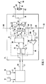
Figur 1 zeigt ein Übersichtsblockschaltbild eines Steuersystems zur Ansteuerung eines Leistungsstellelements, bei dem die erfindungsgemäße Vorgehensweise realisiert ist. Dabei ist mit 10 ein Rechenelement dargestellt, welches über die Eingangsleitungen 12 bis 14, welche das Rechenelement 10 mit Meßeinrichtungen 16 bis 18 verbindet, verfügt. Ferner weist das Rechenelement 10 Ausgangsleitungen 20 und 22 auf, welche auf eine Ansteuerschaltung 24 führen. Die Ausgangsleitung 20 führt dabei auf eine Logikeinheit 25, der außerdem die Leitung 22 und eine Leitung 96 zugeführt sind. Die vier Ausgangsleitungen 32, 34, 36 und 38 der Logikeinheit 25 führen auf jeweils ein Schaltelement einer Vollbrückenendstufe 40.FIG. 1 shows an overview block diagram of a control system for controlling a power control element, in which the procedure according to the invention is implemented. 10 shows a computing element which has the
In einem bevorzugten Ausführungsbeispiel umfaßt die Logikeinheit 25 eine erste Logikschaltung 26, der die Leitung 20 zugeführt wird und deren Ausgangsleitung 28 auf eine Logikanordnung 30 führt, sowie eine zweite Logikschaltung 42, der die Leitung 22 zugeführt ist und deren Ausgangsleitung 44 ebenfalls auf die Logikanordnung 30 führt.In a preferred exemplary embodiment, the
Die Vollbrückenschaltung besteht aus einem ersten Schaltelement 46, dem die Leitung 32 zugeordnet ist und welches über die Leitung 48 mit dem positiven Pol 50 der Betriebsspannung, andererseits über eine Leitung 52 mit einem zweiten Schaltelement 54 verbunden ist, dem die Leitung 38 zugeordnet ist und welches über die Leitung 56, den Meßwiderstand 58 sowie die Leitung 60 mit dem negativen Pol 62 der Betriebsspannung verknüpft ist. Ferner weist die Vollbrückenschaltung 40 ein drittes Schaltelement 64 auf, welches über die Leitung 66 mit dem positiven Pol 50 der Betriebsspannung, über die Leitung 68 mit dem vierten Schaltelement 70 verknüpft ist, welches über die Leitung 52, den Widerstand 58 und die Leitung 60 mit dem negativen Pol 62 der Betriebsspannung verbunden ist. Dabei ist dem Schaltelement 64 die Leitung 34 und dem Schaltelement 70 die Leitung 36 zugeordnet. Von der Leitung 68 führt eine Leitung 74 zum Anschlußpunkt 76 der Schaltungsanordnung 24, während von der Leitung 52 eine Leitung 78 zum Anschlußpunkt 80 der Schaltungsanordnung 24 führt. Zwischen den Anschlüssen 76 und 80 ist der elektrische Motor 82, vorzugsweise eine Gleichstrommotor, geschaltet, welcher über eine mechanische Verbindung 84 mit dem Leistungsstellelement 86, insbesondere einer Drosselklappe, verknüpft ist. Von der Leitung 60 führt eine Leitung 88 zur Erfassung des durch die Vollbrückenschaltung fließenden Stromes zum Komparator 90, dessen anderer Eingang mit der Leitung 92 beaufschlagt ist, welche den Komparator 90 mit einer Referenzspannungsquelle 94 verbindet. Die Ausgangsleitung 96 führt auf die Logikeinheit 25, dort jeweils auf die Logikschaltungen 26 und 42.The full-bridge circuit consists of a
Abhängig von den von den Meßeinrichtungen 16 bis 18 erfaßten Betriebsgrößen, vorzugsweise Fahrpedalstellung, Drosselklappenstellung, Motordrehzahl, Motortemperatur, etc., bildet das Rechenelement 10 vorzugsweise im Rahmen einer Lageregelung Ausgangssignale zur Einstellung des Leistungsstellelements bzw. des Motors 82. Diese werden für die erste Drehrichtung über die Leitung 20, für die zweite Drehrichtung über die Leitung 22 an die Ansteuervorrichtung 24 in Form eines impulsförmigen, im bevorzugtem Ausführungsbeispiel pulsweitenmodulierten Signals abgegeben. Dabei legt die Pulsweite die Dauer der Bestromungsphase des Motors fest und somit die Einstellung des Leistungsstellelements. Dieses pulsweitenmodulierte Signal wird über die entsprechende Leitung auf die erste Logikschaltung 26 und 42 geführt und dort mit dem logischen Ausgangssignal des Komparators 90, welches über die Leitung 96 den Logikschaltungen zugeführt wird, verglichen. Dabei kannn die Logikschaltung 26 bzw. 42 dadurch aufgebaut werden, daß das pulsweitenmodulierte Signal invertiert und das invertierte pulsweidenmodulierte Signal mit dem Komparatorausgangssignalpegel über eine logische NOR-funktion verknüpft wird. Die Logikschaltung muß dabei die Funktion erfüllen, daß auf der Ausgangsleitung 28 bzw. 44 ein hoher Signalpegel ansteht, wenn das pulsweitenmodulierte Impulssignal einen hohen Signalpegel aufweist, der Komparatorausgangssignalpegel jedoch niedrig, in allen anderen Fällen das Signal auf der Leitung 28 bzw. 44 niedrigen Pegel aufweist, Dabei sind neben der oben erwähnten Realsierung auch andere Verknüpfungen vorteilhaft.Depending on the operating variables detected by the measuring
Der Signalpegel auf der Leitung 96 wird vom Komparator 90 durch Vergleich der über den Meßwiderstand 58 anfallenden Spannung mit der vom Element 94 erzeugten Referenzspannung gebildet. Diese Referenzspannung ist so festgelegt, daß der Spannungswert einem vorgegebenen Grenzwert des durch den Verbaucher und die Brücke fliessenden Stroms entspricht. Überschreitet die über den Meßwiderstand 58 abgefallene Spannung den Referenzspannungswert, so zeigt dies einen den vorgegebenen Grenzwert überschreitenden Strom an. Der Ausgangssignalpegel des Komparators 90 wechselt dann auf hohen Pegel. Weist der Komparatorausgang einen hohen Signalpegel auf, so sperren die logischen Schaltungen 26 bzw. 42 einen möglicherweise anstehenden hohen Signalpegel des pulsweitenmodulierten Signals, so daß die Ansteuerung solange unterbrochen ist, bis der Komparator seinen Pegel wieder wechselt, das heißt die am Widerstand 58 abgefallene Spannung unter den Referenzwert sinkt.The signal level on
Die Logikanordnung 30 empfängt die über die Leitung 28 bzw. 44 zugeführten Signale und wählt entsprechend der ankommenden Signale die entsprechenden Leitungen zur Betätigung von Schaltelementen der Vollbrückenendstufe aus. Dabei wird bei positivem Signalpegel auf der Leitung 28 eine Bestromung in Vorwärtsrichtung ausgelöst, indem die Elemente 64 und 54 über die Leitungen 34 und 38 geschlossen werden, während beim negativen Signalpegel auf der Leitung 28 die Freilaufphase angenommen wird und entweder alle Schaltelemente geöffnet oder in einem bevorzugten Ausführungsbeispiel die Schaltelemente 64 und 46 über die Leitungen 34 und 32 geschlossen werden, so daß der Strom nicht zurück ins Bordnetz fließt, sondern sich in der Brücke freiläuft. Entsprechend werden von der Logikanordnung 30 die Signale auf der Leitung 44 behandelt, wobei ein positiver Signalpegel auf der Leitung 44 eine Betätigung des Motors in Rückwärtsrichtung anzeigt, so daß zur Bestromungsphase die Schaltelemente 70 und 46 über die Leitungen 32 und 36 geschlossen werden. Auch hier wird bei niedrigem Signalpegel auf der Leitung 44 die Freilaufphase angenommen und alle Schaltelemente geöffnet oder im bevorzugten Ausführungsbeispiele die Schaltelemente 64 und 46 geschlossen, damit der Strom nicht ins Bordnetz zurückfließt.The
Überschreitet demnach der Spannungsabfall am Meßwiderstand 58 den eingestellten Wert, so wird die Endstufe in die Freilaufphase überführt, die Ansteuerung unterbrochen, so daß im Endeffekt der durch den Motor 82 fließende Strom auf den voreingestellten Wert begrenzt wird. Sobald der abgefallene Spannungswert den eingestellten unterschreitet, wechselt der Signalpegel am Ausgang des Komparators, so daß die Endstufe wieder freigegeben wird und der positive Signalpegel des pulsweitenmodulierten Signals seine Bestromungswirkung wiedererlangt und den Motor entsprechend betätigt.Accordingly, if the voltage drop across the measuring
Neben der dargestellten bevorzugten Ausführungsform kann in anderen Auführungsformen anstelle der dargestellten positiven Logik negative Logik eingesetzt werden, d.h. die Bestromungsphase kann durch einen niedrigen Pegel des Ansteuersignals auf den Leitung 20 und 22 und/oder den Leitungen 32, 34, 36, 38 ausgelöst werden, während der Freilaufphase hoher Signalpegel zugeordnet ist. Ferner kann der Komparator 90 über eine Hysterese verfügen.In addition to the preferred embodiment shown, in other embodiments, negative logic may be used in place of the positive logic shown, i.e. the energization phase can be triggered by a low level of the control signal on
Das Prinzip des eingesetzten Kurzschlußschutzes ist in Fig. 3 gezeigt. Jedes der Schaltelemente 46, 54, 64 und 70 umfaßt Mittel zur Erfassung des durch das jeweilige Schaltelement fließenden Strom (z.B. durch den Einsatz sogenannter "current-sense-FETs"). Überschreitet der durch ein einzelnes Schaltelement fliessende Strom einen Kurzschlußstromschwellwert, wird zumindest dieses Schaltelement abgeschaltet. Diese Maßnahme bezüglich der Kurzschlußfestigkeit der Endstufe ist unabhängig von der Begrenzung des durch die Endstufe fliessenden Stroms. Am Beispiel des Schaltelements 46 der Transistor 100 mit Stromerfassung 102 gezeigt. Der erfaßte Strom wird über eine Leitung 104 auf einen Vergleicher 106 geführt. Dort wird er mit dem voreingestellten Stromwert Imax, dem Kurzschlußstrom, verglichen und ein Ausgangssignal erzeugt, wenn der erfaßte Strom den Grenzwert überschreitet. In einem NAND-Gatter 110 wird die Ausgangsleitung 108 des Vergleichers und die Ansteuerleitung 32 des Schaltelements 46 zusammengeführt. Die Ansteuerung des Transistors wird dadurch bei Überschreiten des Kurzschlußstromwertes im Kurzschlußfall unterbrochen. Das Zusammenspiel zwischen dieser Strombegrenzung durch die einzelnen Schaltelemente und der Strombegrenzung durch die gesamte Brücke ergibt sich daraus, daß bei Fehlerströmen, insbesondere Kurzschlußströmen, die durch Kurzschluß durch den elektrischen Verbraucher (Kurzschluß nach Plus) entstehen, der Strom durch den Verbraucher auf den Grenzwert begrenzt wird. Da diese Maßnahme beispielsweise bei einem Kurzschluß eine Verbraucherklemme nach Masse keinen Schutz bietet (z.B. Kurzschluß durch Transistor 64 bei Ansteuerung), ist eine Überwachung des Stromes durch die einzelnen Transistoren vorgesehen, die im Fehlerfall bei Auftreten des Kurzschlusses die Endstufe in einen sicheren Zustand führt. Die Reaktion besteht in der Abschaltung der Endstufe.The principle of the short-circuit protection used is shown in FIG. 3. Each of the switching
Durch die erfindungsgemäße Vorgehensweise der zusätzlichen Strombegrenzung einer kurzschlußfesten Endstufe wird ein Kappen der Einschalt- und Reversierstromspitze beim Verstellvorgang erreicht , ohne daß ein wesentlicher Verlust an Verstellzeit die Folge ist.The inventive procedure of the additional current limitation of a short-circuit-proof output stage results in a capping of the inrush and reversing current peak during the adjustment process without a substantial loss of adjustment time being the result.
Dies ist anhand der Signalverläufe in Figur 2 am Beispiel der Steuerung eines Gleichstrommotors 82 von einer ersten Stellung auf eine zweite Position dargestellt. Dabei ist jeweils waagrecht die Zeit, in Figur 2a senkrecht der Stellung alpha des Leistungsstellements, der Drosselklappe, in Figur 2b der durch den Motor fließende Strom aufgetragen. Dabei wird angenommen, daß der Motor in einer Stellung alphal steht und von einem Strom I1 in dieser Position gehalten wird. Zum Zeitpunkt T0 erfolgt eine sprungförmige Veränderung des Ansteuersignals im Sinne eines Schließens der Drosselklappe. Dies hat eine abrupte Stromerhöhung zur Folge, der in einer Realisierungsform ohne die erfindungsgemäße Vorgehensweise den Wert I2 erreicht hätte (strichliert dargestellt). Durch die erfindungsgemäße Vorgehensweise wird dieser Strom wie durch die durchgezogene Linie dargestellt begrenzt, z.B. auf 5 A, so daß die strichliert gezeichnete Einschaltspitze vermieden wird. Danach setzt sich der Motor in Bewegung, so daß der Strom absinkt, bis der Motor seine Verstellgeschwindigkeit erreicht hat. Zum Zeitpunkt T1 wird der Motor gebremst, da er sich seiner neuen Position alpha0 nähert. Dies führt zu einer Gegenspannung, die in der Realisierungsform ohne die erfindungsgemäße Vorgehensweise die strichliert gezeichnete Stromspitze I3, z.B. -15 A, zur Folge hätte. Durch die erfindungsgemäße Vorgehensweise wird jedoch auch diese Reversierstromspitze begrenzt, z.B. auf -5 A oder einen anderen Wert. Danach pegelt sich der Strom langsam auf den Haltestrom ein, welcher im Bereich des vorherigen Stromwerts liegt. Anhand Figur 2a wird deutlich, daß die durch die erfindungsgemäße Vorgehensweise erreichte Verstellung des Motors nur unwesentlich von der strichliert gezeigten Verstellkurve ohne die erfindungsgemäße Vorgehensweise abweicht. Eine wesentliche Verringerung der Verstellzeit ist nicht zu erkennen.This is based on the signal curves in FIG. 2, using the example of controlling a
Neben der dargestellten Ausführungsform bei der Steuerung einer Drosselklappe kann die erfindungsgemäße Vorgehensweise auch in Verbindung mit der Ansteuerung eines Einspritzpumpenhebels eines Dieselmotors Verwendung finden.In addition to the illustrated embodiment for controlling a throttle valve, the procedure according to the invention can be used can also be used in connection with the control of an injection pump lever of a diesel engine.
Ferner kann der Komparator 90 mit Meßwiderstand 58 und Referenzspannungsquelle 94 außerhalb des Endstufenbausteins 24 angebracht sein.Furthermore, the
Ferner kann die erfindungsgemäße Vorgehensweise der Strombegrenzung auch mit anderen schaltungstechnischen Realisierungen einer Vollbrückenendstufe mit Ansteuerung Anwendung finden. Kurzschlußmaßnahmen sind aus Übersichtlichkeitsgründen nicht dargestellt, jedoch selbstverständlich im Rahmen der Endstufe realisiert.Furthermore, the current limiting procedure according to the invention can also be used with other circuitry implementations of a full-bridge output stage with control. Short-circuit measures are not shown for reasons of clarity, but of course implemented in the context of the final stage.
Neben der Vorgabe eines Begrenzungswerts für positive und negative Ströme können in vorteilhafter Weise zwei Grenzwerte vorgesehen sein, z.B. kann zur Verstellung in Schließrichtung der Drosselklappe ein größerer Strom zugelassen werden.In addition to specifying a limit value for positive and negative currents, two limit values can advantageously be provided, e.g. a larger current can be permitted for adjustment in the closing direction of the throttle valve.
Die Grenzwerte können in vorteilhafter Weise auch abhängig von Betriebsgrößen wie Brennkraftmaschinen, Motortemperatur, Wicklungstemperatur, Umgebungstemperatur Stellung der Drosselklappe, etc. vorgegebenen sein. Besonders kann die Strombegrenzung in einem vorteilhaften Ausführungsbeispiel durch den Rechner über eine nicht dargestellte Leitung in bestimmten Betriebssituationen aufgehoben werden, z.B. wenn die Drosselklappe klemmt oder festgefroren ist.The limit values can advantageously also be predetermined depending on operating variables such as internal combustion engines, motor temperature, winding temperature, ambient temperature, position of the throttle valve, etc. In an advantageous exemplary embodiment, the current limitation can in particular be canceled by the computer via a line (not shown) in certain operating situations, e.g. if the throttle valve is stuck or frozen.
Die erfindungsgemäße Berenzung des Stromes ist dabei derart ausgebildet, daß im zeitlichen Mittel ein dem vorbestimmten Grenzwert entsprechender Strom durch den Verbraucher und die Endstufe fließt.The limitation of the current according to the invention is designed in such a way that, on average over time, a current corresponding to the predetermined limit value flows through the consumer and the output stage.
Claims (10)
- Device for driving the throttle valve of a drive unit of a vehicle,- having a full-bridge output stage (24) which is protected against short circuits, supplies an electric motor (82), which is connected to the throttle valve, with current and comprises the switching elements (46, 54, 64, 70) which are driven by means of at least one pulsed signal,- having current limiting means (90) for the current which flows through the full-bridge output stage and the connected motor and, when at least one preset limit value (94) is exceeded, is limited to this limit value as a result of blanking of the driving, the driving being resumed when the current falls below the limit value,- having short-circuit monitoring means (106) which monitor the current through each switching element of the output stage and, in the event of a short circuit in at least one of the switching elements, switch the full-bridge output stage off.
- Device according to Claim 1, characterized in that the pulsed drive signal is a pulse-width-modulated signal.
- Device according to one of the preceding claims, characterized in that the full-bridge output stage is driven in the context of energization phases for the two directions of rotation of the motor together with a freewheeling phase.
- Device according to one of the preceding claims, characterized in that when the at least one preset limit value is exceeded during an energization phase, the latter is interrupted and the freewheeling phase is initiated in that all the switching elements are opened or two opposite switching elements are closed.
- Device according to one of the preceding claims, characterized in that the at least one preset limit value has a smaller magnitude than the magnitudes of the peak values of the current profile during normal operation when the DC motor is adjusted.
- Device according to one of the preceding claims, characterized in that the limit value is predetermined as a function of the current direction and/or of operating parameters.
- Device according to one of the preceding claims, characterized in that a computing element (10) is provided which can cancel the limit value in predetermined operating situations or can increase the magnitude of the said limit value.
- Device according to one of the preceding claims, characterized in that hysteresis is provided between blanking and reactivating the driving as regards the current values.
- Device according to one of the preceding claims, characterized in that means (102) are provided which detect the current through each switching element of the output stage and compare it with a threshold value, and when the latter is exceeded, at least this switching element is switched off.
- Device according to one of the preceding claims, characterized in that the full-bridge circuit is integrated in an output stage module and the current limiting is set by external circuitry of the output stage.
Applications Claiming Priority (3)
| Application Number | Priority Date | Filing Date | Title |
|---|---|---|---|
| DE4327483 | 1993-08-16 | ||
| DE4327483A DE4327483A1 (en) | 1993-08-16 | 1993-08-16 | Method and device for controlling a power control element of a drive unit of a vehicle |
| PCT/DE1994/000858 WO1995005704A1 (en) | 1993-08-16 | 1994-07-23 | Device for driving a power controlling element of a vehicle driving unit |
Publications (2)
| Publication Number | Publication Date |
|---|---|
| EP0714568A1 EP0714568A1 (en) | 1996-06-05 |
| EP0714568B1 true EP0714568B1 (en) | 1997-10-22 |
Family
ID=6495291
Family Applications (1)
| Application Number | Title | Priority Date | Filing Date |
|---|---|---|---|
| EP94921592A Expired - Lifetime EP0714568B1 (en) | 1993-08-16 | 1994-07-23 | Device for driving a power controlling element of a vehicle driving unit |
Country Status (7)
| Country | Link |
|---|---|
| US (1) | US5712550A (en) |
| EP (1) | EP0714568B1 (en) |
| JP (1) | JPH09501817A (en) |
| KR (1) | KR100354476B1 (en) |
| DE (2) | DE4327483A1 (en) |
| ES (1) | ES2109004T3 (en) |
| WO (1) | WO1995005704A1 (en) |
Families Citing this family (23)
| Publication number | Priority date | Publication date | Assignee | Title |
|---|---|---|---|---|
| EP0739084B1 (en) * | 1995-04-22 | 2002-07-24 | PAPST-MOTOREN GmbH & Co. KG | Method for control or regulation of an electric motor and arrangement for executing such a method |
| GB9604431D0 (en) * | 1996-03-01 | 1996-05-01 | Lucas Ind Plc | Circuit for testing an electrical actuator drive stage |
| JP3665419B2 (en) * | 1996-05-02 | 2005-06-29 | 新電元工業株式会社 | Inductive load driving method and H-bridge circuit control device |
| DE19721490A1 (en) * | 1997-05-23 | 1998-11-26 | Thomson Brandt Gmbh | Circuit arrangement and method for operating an electronic motor |
| DE19756461A1 (en) * | 1997-12-18 | 1999-07-01 | Bosch Gmbh Robert | Method for influencing the electrical power of a load with a pulse width modulated signal |
| DE19949804A1 (en) | 1998-11-09 | 2000-05-11 | Papst Motoren Gmbh & Co Kg | Electronically commutated motor has arrangement that alters duty ratio of bridge control PWM signal depending on motor parameters to reduce current generated by motor if braking current exceeds threshold |
| JP3724964B2 (en) | 1998-11-18 | 2005-12-07 | 株式会社デンソー | Motor drive device |
| JP3458753B2 (en) | 1999-03-16 | 2003-10-20 | 株式会社デンソー | Motor drive |
| JP3275898B2 (en) | 1999-03-18 | 2002-04-22 | 株式会社デンソー | Motor drive |
| JP3458768B2 (en) | 1999-06-10 | 2003-10-20 | 株式会社デンソー | Load drive |
| ES2252264T3 (en) * | 2000-08-12 | 2006-05-16 | Robert Bosch Gmbh | CIRCUIT PROVISION FOR THE GENERATION OF RECTANGULAR PULSES. |
| DE10137087A1 (en) * | 2001-07-30 | 2003-02-27 | Guido Kuebler Gmbh | Control method for electrically-operated linear actuator or lifting cylinder calculates operating time for motor dependent on difference between actual and required displacement values |
| DE10256045A1 (en) * | 2001-12-15 | 2003-06-26 | Papst Motoren Gmbh & Co Kg | Processing data for electronically commutated motor, involves carrying out computer operation(s) during or outside current pulse duration according to duration comparison |
| JP2004274817A (en) * | 2003-03-05 | 2004-09-30 | Yazaki Corp | Motor forward/reverse drive circuit |
| US7227391B2 (en) * | 2004-04-28 | 2007-06-05 | Matsushita Electric Industrial Co., Ltd. | Semiconductor integrated circuit device and semiconductor integrated circuit system |
| JP2005325741A (en) * | 2004-05-13 | 2005-11-24 | Toyota Motor Corp | Throttle control device |
| US7636227B2 (en) * | 2006-04-21 | 2009-12-22 | International Rectifier Corporation | Noise immune over current protection with inherent current limiting for switching power converter |
| DE102009057709A1 (en) * | 2009-12-10 | 2011-06-16 | Continental Automotive Gmbh | Device for controlling actuators in a motor vehicle |
| US8552672B2 (en) * | 2010-10-19 | 2013-10-08 | Teknic, Inc. | Method and apparatus to drive two-phase motors from a three-phase bridge |
| TWI532285B (en) * | 2012-02-17 | 2016-05-01 | 台達電子工業股份有限公司 | Protection circuit and method for electrical apparatus |
| US20140265560A1 (en) * | 2013-03-15 | 2014-09-18 | Levant Power Corporation | System and method for using voltage bus levels to signal system conditions |
| DE102021103610A1 (en) * | 2021-02-16 | 2022-08-18 | Ebm-Papst Mulfingen Gmbh & Co. Kg | Electric motor, electronics module for an electric motor, method for setting a reference voltage and method for manufacturing a large number of electric motors |
| DE102021114525B4 (en) | 2021-06-07 | 2023-03-02 | Webasto SE | Reduction of radiated interference emissions with AC driven loads |
Citations (1)
| Publication number | Priority date | Publication date | Assignee | Title |
|---|---|---|---|---|
| EP0060331A1 (en) * | 1981-03-12 | 1982-09-22 | Siemens Aktiengesellschaft | Short-circuit protection device for a direct current actuator |
Family Cites Families (11)
| Publication number | Priority date | Publication date | Assignee | Title |
|---|---|---|---|---|
| US4705997A (en) * | 1986-02-21 | 1987-11-10 | United Technologies Automotive, Inc. | Bidirectional motor drive circuit |
| DE3625091A1 (en) * | 1986-07-24 | 1988-01-28 | Bosch Gmbh Robert | POWER STAGE IN BRIDGE CONTROL |
| US4794312A (en) * | 1986-09-29 | 1988-12-27 | Hitachi, Ltd. | Method and apparatus for controlling a servo motor |
| US4703238A (en) * | 1987-01-13 | 1987-10-27 | Design Components, Incorporated | Amplifier system for D.C. motor |
| DE3718309A1 (en) * | 1987-05-21 | 1988-12-15 | Vdo Schindling | CIRCUIT ARRANGEMENT FOR THE CLOCKED CONTROL OF SEMICONDUCTOR SWITCHES |
| US4985666A (en) * | 1988-08-30 | 1991-01-15 | Sony Corporation | Safety device for video cassette recorder |
| JPH02211082A (en) * | 1989-02-08 | 1990-08-22 | Toshiba Corp | Electric brake |
| DE4024160A1 (en) * | 1989-08-11 | 1991-02-14 | Siemens Ag | DC level controller with antiphase clocked switch pairs - performs two-term control of inductive load current maintained at desired value by selective switching circuit |
| US5111123A (en) * | 1990-11-16 | 1992-05-05 | Delco Electronics Corporation | Motor driver interface fault detection apparatus using initial turn-on and noise timers |
| US5264767A (en) * | 1992-01-21 | 1993-11-23 | General Motors Corporation | Electro-hydraulic control apparatus for improved hydraulic pressure control |
| US5457364A (en) * | 1994-01-18 | 1995-10-10 | Allegro Microsystems, Inc. | Bridge motor driver with short-circuit protection and motor-current limiting feature |
-
1993
- 1993-08-16 DE DE4327483A patent/DE4327483A1/en not_active Ceased
-
1994
- 1994-07-23 EP EP94921592A patent/EP0714568B1/en not_active Expired - Lifetime
- 1994-07-23 KR KR1019960700778A patent/KR100354476B1/en not_active IP Right Cessation
- 1994-07-23 ES ES94921592T patent/ES2109004T3/en not_active Expired - Lifetime
- 1994-07-23 US US08/596,345 patent/US5712550A/en not_active Expired - Lifetime
- 1994-07-23 JP JP7506675A patent/JPH09501817A/en active Pending
- 1994-07-23 DE DE59404441T patent/DE59404441D1/en not_active Expired - Lifetime
- 1994-07-23 WO PCT/DE1994/000858 patent/WO1995005704A1/en active IP Right Grant
Patent Citations (1)
| Publication number | Priority date | Publication date | Assignee | Title |
|---|---|---|---|---|
| EP0060331A1 (en) * | 1981-03-12 | 1982-09-22 | Siemens Aktiengesellschaft | Short-circuit protection device for a direct current actuator |
Also Published As
| Publication number | Publication date |
|---|---|
| WO1995005704A1 (en) | 1995-02-23 |
| JPH09501817A (en) | 1997-02-18 |
| EP0714568A1 (en) | 1996-06-05 |
| KR100354476B1 (en) | 2003-01-06 |
| ES2109004T3 (en) | 1998-01-01 |
| DE4327483A1 (en) | 1995-02-23 |
| DE59404441D1 (en) | 1997-11-27 |
| US5712550A (en) | 1998-01-27 |
Similar Documents
| Publication | Publication Date | Title |
|---|---|---|
| EP0714568B1 (en) | Device for driving a power controlling element of a vehicle driving unit | |
| DE3414592C2 (en) | ||
| DE2926938A1 (en) | SWITCHING ARRANGEMENT FOR DRIVING A MOVABLE ELEMENT, ESPECIALLY FOR DRIVING DISCS OR THE LIKE. IN MOTOR VEHICLES | |
| EP0848159A1 (en) | Starting device for an internal combustion engine | |
| DE10151177A1 (en) | Steering control device | |
| DE4329919A1 (en) | Method for operating a consumer in a vehicle | |
| DE19813797A1 (en) | Device for controlling the flow of current through a series of inductive loads | |
| DE4030533A1 (en) | ARRANGEMENT FOR MONITORING A CONSUMER IN CONNECTION WITH AN INTERNAL COMBUSTION ENGINE OR. A MOTOR VEHICLE | |
| DE3733623A1 (en) | DEVICE FOR ADJUSTING THE OPERATING CHARACTERISTICS OF AN INTERNAL COMBUSTION ENGINE | |
| DE4041620C2 (en) | Device for power supply for devices with overrun | |
| EP1540431B1 (en) | Method for regulating the current flowing through an electromagnetic actuator | |
| DE19811176A1 (en) | Control circuit for starter motor in vehicle | |
| WO2016166146A1 (en) | Electronic control device protected against overvoltage | |
| EP0371151B1 (en) | Safety circuit for an electronic speed control system for motor vehicles | |
| EP0920722B1 (en) | Generator control system | |
| EP1107440B1 (en) | Method and circuit for switching on a power output stage | |
| EP0780032B1 (en) | Circuit for operating an electric motor | |
| WO2005008877A1 (en) | Monitoring circuit for an electric motor and method for monitoring an electric motor | |
| DE4134495A1 (en) | CONTROL DEVICE FOR ELECTRIC MOTORS IN VEHICLES | |
| WO2001061835A2 (en) | Method for controlling an electric driving motor of an adjusting device pertaining to a motor vehicle | |
| EP2671317A2 (en) | Assembly for controlling an electric vacuum pump | |
| DE102005046993B3 (en) | Output signal producing device for use in semiconductor switch, has impact device formed in such manner to output intermediate signal as output signal to output signal output when load current does not fulfill predetermined condition | |
| EP1011190B1 (en) | Method and circuit for monitoring the operational status of a charge | |
| WO1986002127A1 (en) | Circuit arrangement for current control by an electrical, in particular electromagnetic, consumer | |
| EP0849753A2 (en) | Switched output stage for controlling or regulating inductive loads |
Legal Events
| Date | Code | Title | Description |
|---|---|---|---|
| PUAI | Public reference made under article 153(3) epc to a published international application that has entered the european phase |
Free format text: ORIGINAL CODE: 0009012 |
|
| 17P | Request for examination filed |
Effective date: 19960318 |
|
| AK | Designated contracting states |
Kind code of ref document: A1 Designated state(s): DE ES FR GB |
|
| RIN1 | Information on inventor provided before grant (corrected) |
Inventor name: MUELLER, KLAUS Inventor name: ZELLER, THOMAS Inventor name: BOLL, LEONHARD |
|
| 17Q | First examination report despatched |
Effective date: 19960703 |
|
| RIN1 | Information on inventor provided before grant (corrected) |
Inventor name: MUELLER, KLAUS Inventor name: ZELLER, THOMAS Inventor name: BOLL, LEONHARD |
|
| RIN1 | Information on inventor provided before grant (corrected) |
Inventor name: MUELLER, KLAUS Inventor name: ZELLER, THOMAS Inventor name: BOLL, LEONHARD |
|
| GRAG | Despatch of communication of intention to grant |
Free format text: ORIGINAL CODE: EPIDOS AGRA |
|
| GRAH | Despatch of communication of intention to grant a patent |
Free format text: ORIGINAL CODE: EPIDOS IGRA |
|
| GRAH | Despatch of communication of intention to grant a patent |
Free format text: ORIGINAL CODE: EPIDOS IGRA |
|
| GRAA | (expected) grant |
Free format text: ORIGINAL CODE: 0009210 |
|
| AK | Designated contracting states |
Kind code of ref document: B1 Designated state(s): DE ES FR GB |
|
| ET | Fr: translation filed | ||
| REF | Corresponds to: |
Ref document number: 59404441 Country of ref document: DE Date of ref document: 19971127 |
|
| REG | Reference to a national code |
Ref country code: ES Ref legal event code: FG2A Ref document number: 2109004 Country of ref document: ES Kind code of ref document: T3 |
|
| GBT | Gb: translation of ep patent filed (gb section 77(6)(a)/1977) |
Effective date: 19980108 |
|
| PLBI | Opposition filed |
Free format text: ORIGINAL CODE: 0009260 |
|
| PLBF | Reply of patent proprietor to notice(s) of opposition |
Free format text: ORIGINAL CODE: EPIDOS OBSO |
|
| 26 | Opposition filed |
Opponent name: MANNESMANN VDO AG Effective date: 19980722 |
|
| PLBF | Reply of patent proprietor to notice(s) of opposition |
Free format text: ORIGINAL CODE: EPIDOS OBSO |
|
| PLBO | Opposition rejected |
Free format text: ORIGINAL CODE: EPIDOS REJO |
|
| APAC | Appeal dossier modified |
Free format text: ORIGINAL CODE: EPIDOS NOAPO |
|
| APAE | Appeal reference modified |
Free format text: ORIGINAL CODE: EPIDOS REFNO |
|
| APAC | Appeal dossier modified |
Free format text: ORIGINAL CODE: EPIDOS NOAPO |
|
| PLBN | Opposition rejected |
Free format text: ORIGINAL CODE: 0009273 |
|
| STAA | Information on the status of an ep patent application or granted ep patent |
Free format text: STATUS: OPPOSITION REJECTED |
|
| REG | Reference to a national code |
Ref country code: GB Ref legal event code: IF02 |
|
| 27O | Opposition rejected |
Effective date: 20011004 |
|
| APAH | Appeal reference modified |
Free format text: ORIGINAL CODE: EPIDOSCREFNO |
|
| PGFP | Annual fee paid to national office [announced via postgrant information from national office to epo] |
Ref country code: FR Payment date: 20110729 Year of fee payment: 18 |
|
| PGFP | Annual fee paid to national office [announced via postgrant information from national office to epo] |
Ref country code: ES Payment date: 20110728 Year of fee payment: 18 Ref country code: GB Payment date: 20110721 Year of fee payment: 18 |
|
| GBPC | Gb: european patent ceased through non-payment of renewal fee |
Effective date: 20120723 |
|
| REG | Reference to a national code |
Ref country code: FR Ref legal event code: ST Effective date: 20130329 |
|
| PG25 | Lapsed in a contracting state [announced via postgrant information from national office to epo] |
Ref country code: GB Free format text: LAPSE BECAUSE OF NON-PAYMENT OF DUE FEES Effective date: 20120723 Ref country code: FR Free format text: LAPSE BECAUSE OF NON-PAYMENT OF DUE FEES Effective date: 20120731 |
|
| REG | Reference to a national code |
Ref country code: ES Ref legal event code: FD2A Effective date: 20131018 |
|
| PG25 | Lapsed in a contracting state [announced via postgrant information from national office to epo] |
Ref country code: ES Free format text: LAPSE BECAUSE OF NON-PAYMENT OF DUE FEES Effective date: 20120724 |
|
| PGFP | Annual fee paid to national office [announced via postgrant information from national office to epo] |
Ref country code: DE Payment date: 20130926 Year of fee payment: 20 |
|
| REG | Reference to a national code |
Ref country code: DE Ref legal event code: R071 Ref document number: 59404441 Country of ref document: DE |
|
| PG25 | Lapsed in a contracting state [announced via postgrant information from national office to epo] |
Ref country code: DE Free format text: LAPSE BECAUSE OF EXPIRATION OF PROTECTION Effective date: 20140724 |