EP1540221B1 - Method for curing a thermocurable matrix - Google Patents
Method for curing a thermocurable matrix Download PDFInfo
- Publication number
- EP1540221B1 EP1540221B1 EP03766099A EP03766099A EP1540221B1 EP 1540221 B1 EP1540221 B1 EP 1540221B1 EP 03766099 A EP03766099 A EP 03766099A EP 03766099 A EP03766099 A EP 03766099A EP 1540221 B1 EP1540221 B1 EP 1540221B1
- Authority
- EP
- European Patent Office
- Prior art keywords
- strip
- pipes
- curing
- line
- medium
- Prior art date
- Legal status (The legal status is an assumption and is not a legal conclusion. Google has not performed a legal analysis and makes no representation as to the accuracy of the status listed.)
- Expired - Lifetime
Links
- 238000000034 method Methods 0.000 title claims description 16
- 239000011159 matrix material Substances 0.000 title claims description 7
- XLYOFNOQVPJJNP-UHFFFAOYSA-N water Substances O XLYOFNOQVPJJNP-UHFFFAOYSA-N 0.000 claims abstract description 25
- 239000004753 textile Substances 0.000 claims abstract description 5
- 238000003825 pressing Methods 0.000 claims description 3
- 239000000126 substance Substances 0.000 claims description 3
- 239000012530 fluid Substances 0.000 claims 1
- 239000002699 waste material Substances 0.000 claims 1
- 239000004744 fabric Substances 0.000 description 4
- 239000000463 material Substances 0.000 description 3
- 238000003780 insertion Methods 0.000 description 2
- 230000037431 insertion Effects 0.000 description 2
- 238000009434 installation Methods 0.000 description 2
- 239000011347 resin Substances 0.000 description 2
- 229920005989 resin Polymers 0.000 description 2
- 239000010865 sewage Substances 0.000 description 2
- 229910000831 Steel Inorganic materials 0.000 description 1
- 230000005540 biological transmission Effects 0.000 description 1
- 238000007664 blowing Methods 0.000 description 1
- 239000000919 ceramic Substances 0.000 description 1
- 238000004140 cleaning Methods 0.000 description 1
- 238000004891 communication Methods 0.000 description 1
- 239000004567 concrete Substances 0.000 description 1
- 230000001419 dependent effect Effects 0.000 description 1
- 238000009826 distribution Methods 0.000 description 1
- 230000005611 electricity Effects 0.000 description 1
- 239000013505 freshwater Substances 0.000 description 1
- 238000010438 heat treatment Methods 0.000 description 1
- 239000004033 plastic Substances 0.000 description 1
- 238000002360 preparation method Methods 0.000 description 1
- 238000005086 pumping Methods 0.000 description 1
- 238000009418 renovation Methods 0.000 description 1
- 239000010959 steel Substances 0.000 description 1
- 229920001187 thermosetting polymer Polymers 0.000 description 1
Images

Classifications
-
- F—MECHANICAL ENGINEERING; LIGHTING; HEATING; WEAPONS; BLASTING
- F16—ENGINEERING ELEMENTS AND UNITS; GENERAL MEASURES FOR PRODUCING AND MAINTAINING EFFECTIVE FUNCTIONING OF MACHINES OR INSTALLATIONS; THERMAL INSULATION IN GENERAL
- F16L—PIPES; JOINTS OR FITTINGS FOR PIPES; SUPPORTS FOR PIPES, CABLES OR PROTECTIVE TUBING; MEANS FOR THERMAL INSULATION IN GENERAL
- F16L7/00—Supporting of pipes or cables inside other pipes or sleeves, e.g. for enabling pipes or cables to be inserted or withdrawn from under roads or railways without interruption of traffic
- F16L7/02—Supporting of pipes or cables inside other pipes or sleeves, e.g. for enabling pipes or cables to be inserted or withdrawn from under roads or railways without interruption of traffic and sealing the pipes or cables inside the other pipes, cables or sleeves
-
- E—FIXED CONSTRUCTIONS
- E03—WATER SUPPLY; SEWERAGE
- E03F—SEWERS; CESSPOOLS
- E03F3/00—Sewer pipe-line systems
-
- G—PHYSICS
- G02—OPTICS
- G02B—OPTICAL ELEMENTS, SYSTEMS OR APPARATUS
- G02B6/00—Light guides; Structural details of arrangements comprising light guides and other optical elements, e.g. couplings
- G02B6/46—Processes or apparatus adapted for installing or repairing optical fibres or optical cables
- G02B6/50—Underground or underwater installation; Installation through tubing, conduits or ducts
- G02B6/502—Installation methods in fluid conducts, e.g. pipelines
-
- G—PHYSICS
- G02—OPTICS
- G02B—OPTICAL ELEMENTS, SYSTEMS OR APPARATUS
- G02B6/00—Light guides; Structural details of arrangements comprising light guides and other optical elements, e.g. couplings
- G02B6/46—Processes or apparatus adapted for installing or repairing optical fibres or optical cables
- G02B6/50—Underground or underwater installation; Installation through tubing, conduits or ducts
- G02B6/508—Fixation devices in ducts for drawing cables
-
- H—ELECTRICITY
- H02—GENERATION; CONVERSION OR DISTRIBUTION OF ELECTRIC POWER
- H02G—INSTALLATION OF ELECTRIC CABLES OR LINES, OR OF COMBINED OPTICAL AND ELECTRIC CABLES OR LINES
- H02G1/00—Methods or apparatus specially adapted for installing, maintaining, repairing or dismantling electric cables or lines
- H02G1/06—Methods or apparatus specially adapted for installing, maintaining, repairing or dismantling electric cables or lines for laying cables, e.g. laying apparatus on vehicle
- H02G1/08—Methods or apparatus specially adapted for installing, maintaining, repairing or dismantling electric cables or lines for laying cables, e.g. laying apparatus on vehicle through tubing or conduit, e.g. rod or draw wire for pushing or pulling
-
- H—ELECTRICITY
- H02—GENERATION; CONVERSION OR DISTRIBUTION OF ELECTRIC POWER
- H02G—INSTALLATION OF ELECTRIC CABLES OR LINES, OR OF COMBINED OPTICAL AND ELECTRIC CABLES OR LINES
- H02G9/00—Installations of electric cables or lines in or on the ground or water
- H02G9/06—Installations of electric cables or lines in or on the ground or water in underground tubes or conduits; Tubes or conduits therefor
-
- H—ELECTRICITY
- H02—GENERATION; CONVERSION OR DISTRIBUTION OF ELECTRIC POWER
- H02G—INSTALLATION OF ELECTRIC CABLES OR LINES, OR OF COMBINED OPTICAL AND ELECTRIC CABLES OR LINES
- H02G9/00—Installations of electric cables or lines in or on the ground or water
- H02G9/10—Installations of electric cables or lines in or on the ground or water in cable chambers, e.g. in manhole or in handhole
Definitions
- the invention relates to a method for curing according to the preamble of patent claim 1.
- the object of the present invention is therefore to provide a method which allows a cost-effective manner optimal curing of pipes for data cables, electrical cables or a gas or liquid-carrying tubes carrying strips of curable material.
- FIG. 1 a conduit or channel of steel, concrete, ceramic or plastic is shown by reference numeral 1, in whose apex S a sickle-shaped strip 4 is visible from a fabric fabric or the like.
- the strip 5 for example, two empty tubes, short tubes 5, embedded for the reception of data or electrical cables.
- the strip 4 is held in the position shown here by an expandable hose 7, which is filled with air, for example.
- the strip 4 could also rest laterally at R or below at T on the inner line wall 9 and be provisionally fixed there before insertion of the tube 7 or be held by a robot 6 and the laying arm 8.
- the strip 4 or the textile supporting structure forming the strip 4 is impregnated with a thermosetting resin as the matrix 3.
- the insertion of the strip 4 in the line 1 can be done in various ways.
- the preferred method uses a robot 6, which inserts the strip 4 into the line 1 and applies it to the pipe inner wall 9 at a suitable location.
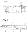
- the inflatable flexible tube 7 is introduced, preferably in a Stülphabilit, ie by blowing air or pumping water, the eversion from the inlet side to the outlet side and the tube 7 moves without relative movement to the strip 4, which is deposited by the robot arm 8 is, on the strip 4 and presses this, as soon as enough pressure in the conduit 7 is constructed, uniformly and firmly against the inner wall 9 of the line 1 ( FIG. 4 ).
- the at least one pipe 5 is connected to a water heater, eg a water heater 13.
- the instantaneous water heater 13 can be powered by gas or electricity.
- the duration of the heat treatment of the strip 4 by passing hot water and the temperature of the water must be determined on a case by case basis and depend on the resin used, which is used as the matrix 3 for the strip 4.
- the invention has been described with reference to the laying of data cable receiving strips 4 of textile material and a curable matrix 3 in non-accessible sewers.
- the same procedure can also be used in walk-in channels, as in larger cities are customary, to be applied.
- a pressurized tube 7 for temporary pressing of the strip 4 with the tubes 5 embedded therein other means such as slats or boards can be used, with which the strip 4 is temporarily pressed against the wall 9, to which it is to adhere.
- pipes for guiding electric wires can be fixed in this way. It is also possible with the inventive method pipes in which later, for example, water or gas to be routed to buildings to insert in this way in lines or channels. It is therefore possible to lead within a sewer pipe and the fresh water and gas supply pipes and the data cable receiving pipes or to introduce these later in sewers or in larger gas supply without having to make digging with the correspondingly high costs.
Abstract
Description
Gegenstand der Erfindung ist ein Verfahren zum Aushärten gemäss Oberbegriff des Patentanspruchs 1.The invention relates to a method for curing according to the preamble of
Die Verlegung von Kommunikations- und anderer Zuleitungen in bebauten Gebieten, insbesondere in städtischen Gebieten, ist mit riesigen Kosten verbunden. Seit einigen Jahren ist bekannt, Datenübertragungskabel in bestehende Abwasserleitungen, d.h. Entsorgungsleitungen, zu verlegen. Anfänglich wurden diese Kabel mittels Klammern und anderen aus der Technik bekannten Befestigungselementen direkt ins Innere der Entsorgungsleitungen eingebracht und mit mechanischen Mitteln befestigt.
Die chemische und mechanische Belastung durch Abwässer und allfällige Reinigungsmassnahmen mit Bürsten oder Wasserstrahl, welche zur Zerstörung der eingelegten Rohre führen können, haben dazu geführt, nach neuen Methoden für die Verlegung zu suchen. Eine solche besteht darin, die Leitungen zwischen einen in die Entsorgungsleitung eingelegten aus einem aushärtbaren Material bestehenden Schlauch und die Kanal- oder Leitungswandung einzulegen. Damit gelingt es einerseits, beschädigte Abwasserleitungen zu sanieren und andererseits Datenleitungen geschützt von chemischen und mechanischen Einflüssen zu verlegen. Dieses Verfahren eignet sich dort, wo ohnehin eine Sanierung der Abwasserleitungen ansteht. Sollen aber ausschliesslich Datenleitungen verlegt werden, mit denen ohne jegliche Grabarbeiten beliebige Gebäude einer Stadt erreichbar sind, so sind die Kosten für diese Verlegungsart zu hoch.The laying of communication and other feeder lines in built-up areas, especially in urban areas, is costly. For some years, it has been known to lay data transmission cables in existing sewers, ie disposal lines. Initially, these cables were inserted by means of clamps and other fasteners known in the art directly into the interior of the disposal lines and fastened by mechanical means.
The chemical and mechanical pollution by sewage and any cleaning measures with brushes or water jet, which destroy the inserted pipes have led to the search for new methods of installation. Such is to insert the lines between an inserted in the disposal line made of a curable material hose and the channel or conduit wall. On the one hand, this means that damaged sewage pipes can be rehabilitated and, on the other hand, that data cables are protected from chemical and mechanical influences. This method is suitable where a renovation of the sewers is pending anyway. However, if only data lines are to be laid with which any buildings of a city can be reached without any digging, the costs for this type of installation are too high.
Aus der
Aufgabe der vorliegenden Erfindung ist daher die Schaffung eines Verfahrens, das auf kostengünstige Weise eine optimale Aushärtung von Rohren für Datenkabel, Elektrokabel oder ein Gas oder Flüssigkeit führende Rohre tragende Streifen aus aushärtbarem Material ermöglicht.The object of the present invention is therefore to provide a method which allows a cost-effective manner optimal curing of pipes for data cables, electrical cables or a gas or liquid-carrying tubes carrying strips of curable material.
Gelöst wird diese Aufgabe durch ein Verfahren gemäss den Merkmalen des Patentanspruchs 1. Vorteilhafte Ausgestaltungen der Erfindung werden in den abhängigen Ansprüchen definiert.This object is achieved by a method according to the features of
Die temporäre Verwendung der beispielsweise für das Aufnehmen von Datenkabeln bereits in Streifen eingelegten Rohren zum Einbringen der notwendigen Aushärtewärme ist nicht nur um ein Vielfaches kostengünstiger, sondern die Wärme wird gezielt nur dort eingebracht, wo sie benötigt wird. Wenige Liter Wasser, die in einem einfachen, beispielsweise gasbetriebenen Durchlauferhitzer erwärmt bzw. während des Aushärtens warmgehalten werden können, genügen, um einen Streifen von der Länge von hundert und mehr Metern auszuhärten. Obwohl die Wärme nur in dem mindestens einen im Streifen vorhandenen Rohr geführt und abgegeben wird, gelingt es, den Streifen über seine gesamte Breite auszuhärten. Bei mehreren Datenkabel aufnehmenden Rohren kann das heisse Wasser durch Verbinden der Rohrenden an einem Ende des Streifens zirkuliert werden und folglich muss nicht das am Ende austretende Wasser ausserhalb des Streifens zurückgeführt oder stets neues heisses Wasser zugeführt werden. Bei mindestens zwei Rohren kann das heisse Wasser in Gegenstrom fliessen. Dies führt zu einer gleichmässigen Wärmezufuhr an den Streifen über die gesamte Länge des Streifens.The temporary use of, for example, for receiving data cables already inserted into strips tubes for introducing the necessary curing heat is not only much cheaper, but the Heat is deliberately introduced only where it is needed. A few liters of water, which can be heated in a simple, for example, gas-powered water heater or kept warm during curing, are sufficient to cure a strip of the length of one hundred and more meters. Although the heat is conducted and discharged only in the at least one pipe present in the strip, it is possible to cure the strip over its entire width. With multiple data pipe receiving pipes, the hot water can be circulated by connecting the pipe ends to one end of the strip, and consequently, it is not necessary to recirculate the end water out of the strip or to always supply new hot water. With at least two pipes, the hot water can flow in countercurrent. This results in a uniform supply of heat to the strip over the entire length of the strip.
Anhand eines illustrierten Ausführungsbeispiels für die Verlegung von Datenkabel aufnehmenden Rohren in Entsorgungsleitungen wird die Erfindung näher erläutert. Es zeigen
Figur 1- einen Querschnitt durch eine kommunale Entsorgungs- oder eine Versorgungsleitung,
- Figur 2
- einen Querschnitt durch einen Strassenzug mit zwei Schächten und einer zwischen den Schächten verlaufenden Entsorgungsleitung,
- Figur 3
- einen Querschnitt durch eine kommunale Entsorgungsleitung zwischen zwei Schächten vergrössert dargestellt,
- Figur 4
- einen Längsschnitt durch die
Leitung 1 und denflexiblen Schlauch 7 während des Umstülpens und Anlegens an den bereits in der Leitung liegenden mit einem Roboter ausgelegten Streifen.
- FIG. 1
- a cross section through a municipal disposal or supply line,
- FIG. 2
- a cross section through a road train with two shafts and one between the shafts running disposal line,
- FIG. 3
- shows a cross section through a municipal disposal line between two shafts enlarged,
- FIG. 4
- a longitudinal section through the
conduit 1 and theflexible tube 7 during everting and applying to the lying already in the line with a robot-designed strip.
In
Durch diese Massnahme kann nebst einer optimalen Ausnutzung des erwärmten Wassers auch eine optimale Wärmeverteilung längs des auszuhärtenden Abschnitts L zwischen den beiden Schächten A und B erreicht werden.By this measure, in addition to an optimal utilization of the heated water and an optimal heat distribution along the portion L to be cured between the two shafts A and B can be achieved.
Für die Dehnung des flexiblen Schlauchs 7 zum Anpressen des Streifens 4 genügt in diesem Fall Kaltluft oder kaltes Wasser, die bzw. das einerseits schnell und vor allem kostengünstig in den Schlauch 7 eingepresst werden kann. Allfällige kleine Leckstellen des Schlauchs 7 sind nicht von grossem Belang, da der Leckageverlust ohne weiteres von der Pumpe ausgeglichen werden kann. Der Schlauch 7 und die für das Aufblasen oder das Zuführen von kalten Wasser notwendige Pumpe sind in
Die Dauer der Wärmebehandlung des Streifens 4 durch Hindurchführen von heissem Wasser und die Temperatur des Wassers müssen von Fall zu Fall bestimmt werden und hängen vom verwendeten Harz ab, das als Matrix 3 für den Streifen 4 eingesetzt wird.The duration of the heat treatment of the strip 4 by passing hot water and the temperature of the water must be determined on a case by case basis and depend on the resin used, which is used as the matrix 3 for the strip 4.
Die Erfindung wurde anhand der Verlegung von Datenkabel aufnehmenden Streifen 4 aus textilem Material und einer aushärtbaren Matrix 3 in nicht begehbare Abwasserleitungen beschrieben. Selbstverständlich kann das gleiche Verfahren auch in begehbaren Kanälen, wie sie in grösseren Städten üblich sind, angewendet werden. Anstelle von einem unter Druck befindlichen Schlauch 7 zum temporären Anpressen des Streifens 4 mit den darin eingebetteten Rohren 5 können andere Mittel wie beispielsweise Latten oder Bretter verwendet werden, mit denen der Streifen 4 temporär an die Wand 9 anpressbar ist, an der dieser haften soll. Auch können anstelle von Datenleitungen aufnehmenden Rohren 5 Rohre für das Führen von Elektrokabeln auf diese Weise befestigt werden. Ebenso ist es möglich, mit dem erfindungsgemässen Verfahren Rohre, in denen später beispielsweise Wasser oder Gas zu Gebäuden geleitet werden soll, auf diese Weise in Leitungen oder Kanäle einzulegen. Es ist folglich möglich, innerhalb eines Abwasserrohres auch die Frischwasser- und Gaszuführrohre sowie die Datenkabel aufnehmenden Rohre zu führen bzw. diese nachträglich in Abwasserleitungen oder auch in grösseren Gaszuführleitungen einzubringen, ohne Grabarbeiten mit den entsprechend hohen Kosten vornehmen zu müssen.The invention has been described with reference to the laying of data cable receiving strips 4 of textile material and a curable matrix 3 in non-accessible sewers. Of course, the same procedure can also be used in walk-in channels, as in larger cities are customary, to be applied. Instead of a pressurized
Claims (7)
- Method for the curing of pipes (5) for accommodating data cable or electric cable and/or pipes guiding gaseous or fluid substances with a hot medium, the said pipes being laid in municipal supply and waste lines and ducts (1) and being secured by means of a textile securing strip (4) with a thermo-curable matrix (3) on the liner (9), characterised in that the hot medium, after pressing the strip (4) against the line or duct wall with the at least one pipe (5) embedded therein, is conducted through the at least one pipe (5).
- Method for curing according to claim 1, characterised in that hot water or hot steam is used as the medium.
- Method for curing according to claim 1 or claim 2, characterised in that the medium is introduced alternately from two directions into the at least one pipe (5).
- Method for curing according to one of claims 1 to 3, characterised in that where there are several pipes (5), the medium is guided in the counter current by connecting the pipes (5) at one end.
- Method for curing according to one of claims 1 to 4, characterised in that during curing the strip (4) is pressed by an expandable flexible tube (7) against the inside wall (9) of the line (1).
- Method for curing according to one of claims 1 to 4, characterised in that the strip (4) is pressed against the inside wall (9) of the line (1) by a board or a slat during curing.
- Method for curing according to one of claims 1 to 6, characterised in that the strip (4) is positioned onto the inside wall (9) by the arm (8) of a robot (6) that travels in the line (1) directly in front of the front end of an expandable flexible tube (7) that can be inverted in the line (1).
Priority Applications (1)
| Application Number | Priority Date | Filing Date | Title |
|---|---|---|---|
| SI200331367T SI1540221T1 (en) | 2002-08-06 | 2003-07-07 | Method for curing a thermocurable matrix |
Applications Claiming Priority (3)
| Application Number | Priority Date | Filing Date | Title |
|---|---|---|---|
| CH136102 | 2002-08-06 | ||
| CH13612002 | 2002-08-06 | ||
| PCT/CH2003/000447 WO2004013529A1 (en) | 2002-08-06 | 2003-07-07 | Method for curing a thermocurable matrix |
Publications (2)
| Publication Number | Publication Date |
|---|---|
| EP1540221A1 EP1540221A1 (en) | 2005-06-15 |
| EP1540221B1 true EP1540221B1 (en) | 2008-09-03 |
Family
ID=31193662
Family Applications (1)
| Application Number | Title | Priority Date | Filing Date |
|---|---|---|---|
| EP03766099A Expired - Lifetime EP1540221B1 (en) | 2002-08-06 | 2003-07-07 | Method for curing a thermocurable matrix |
Country Status (10)
| Country | Link |
|---|---|
| US (1) | US7691312B2 (en) |
| EP (1) | EP1540221B1 (en) |
| AT (1) | ATE407319T1 (en) |
| AU (1) | AU2003243872A1 (en) |
| DE (1) | DE50310446D1 (en) |
| DK (1) | DK1540221T3 (en) |
| ES (1) | ES2314250T3 (en) |
| PT (1) | PT1540221E (en) |
| SI (1) | SI1540221T1 (en) |
| WO (1) | WO2004013529A1 (en) |
Families Citing this family (3)
| Publication number | Priority date | Publication date | Assignee | Title |
|---|---|---|---|---|
| GB0814665D0 (en) * | 2008-08-12 | 2008-09-17 | Thomas Elfed | Laying network cables in sewers |
| US8571709B2 (en) * | 2010-10-05 | 2013-10-29 | Southeast Directional Drilling, Llc | Remote controlled vehicle |
| US9677262B2 (en) * | 2015-04-06 | 2017-06-13 | Shahriar Eftekharzadeh | Apparatus for pressurized conveyance in gravity conduits |
Family Cites Families (7)
| Publication number | Priority date | Publication date | Assignee | Title |
|---|---|---|---|---|
| US5674030A (en) * | 1991-08-27 | 1997-10-07 | Sika Equipment Ag. | Device and method for repairing building branch lines in inacessible sewer mains |
| US5263515A (en) * | 1992-01-31 | 1993-11-23 | Goodale James R | Device for repairing a tube |
| CA2173127C (en) * | 1994-08-19 | 2002-10-15 | Larry W. Kiest, Jr. | Method and apparatus for repairing a pipeline |
| US20010010781A1 (en) | 1998-07-30 | 2001-08-02 | Martin Prusak | Method of laying data cables and the like in underground pipes and pipe-cable combinations |
| SE0002436D0 (en) | 2000-06-28 | 2000-06-28 | Carl Johan Andersson | Method and apparatus for shaft-free laying of cables or the like internally in pipes and hoses |
| EP1262809A1 (en) | 2001-05-23 | 2002-12-04 | S3 Soncini S.r.l. | Apparatus for cables laying and conduits renovation and methods of its fabrication and installation |
| FR2825772B1 (en) | 2001-06-08 | 2003-09-19 | Ina Acquisition Corp | PROCESS FOR PLACING A CLOTH OF AT LEAST ONE SLEEVE WITHIN A PIPE |
-
2003
- 2003-07-07 DE DE50310446T patent/DE50310446D1/en not_active Expired - Lifetime
- 2003-07-07 US US10/573,209 patent/US7691312B2/en not_active Expired - Fee Related
- 2003-07-07 AU AU2003243872A patent/AU2003243872A1/en not_active Abandoned
- 2003-07-07 SI SI200331367T patent/SI1540221T1/en unknown
- 2003-07-07 AT AT03766099T patent/ATE407319T1/en active
- 2003-07-07 DK DK03766099T patent/DK1540221T3/en active
- 2003-07-07 ES ES03766099T patent/ES2314250T3/en not_active Expired - Lifetime
- 2003-07-07 PT PT03766099T patent/PT1540221E/en unknown
- 2003-07-07 EP EP03766099A patent/EP1540221B1/en not_active Expired - Lifetime
- 2003-07-07 WO PCT/CH2003/000447 patent/WO2004013529A1/en active IP Right Grant
Also Published As
| Publication number | Publication date |
|---|---|
| US20070052140A1 (en) | 2007-03-08 |
| DE50310446D1 (en) | 2008-10-16 |
| DK1540221T3 (en) | 2008-12-15 |
| US7691312B2 (en) | 2010-04-06 |
| WO2004013529A1 (en) | 2004-02-12 |
| AU2003243872A1 (en) | 2004-02-23 |
| ES2314250T3 (en) | 2009-03-16 |
| EP1540221A1 (en) | 2005-06-15 |
| SI1540221T1 (en) | 2009-02-28 |
| PT1540221E (en) | 2008-12-03 |
| ATE407319T1 (en) | 2008-09-15 |
Similar Documents
| Publication | Publication Date | Title |
|---|---|---|
| DE3732694C2 (en) | Process for lining channels | |
| EP0964106A1 (en) | Method for renovating inaccessible pipes and renovated pipe | |
| EP1540221B1 (en) | Method for curing a thermocurable matrix | |
| DE102012213306A1 (en) | Device for utilizing heat from waste water in sewer, has heat exchange tubes that are arranged parallel to each other over cross-sectional contour of profiled strand, and are inserted into bottom portion of sewer | |
| WO1999065129A1 (en) | Method for installing at least one pipe line and/or an empty conduit in supply and sanitation pipes which have already been laid, especially in sewer pipe systems or networks and similar | |
| DE102019100276A1 (en) | Method and device for the rehabilitation of a pipe section of a pipeline system | |
| EP1006638B1 (en) | Method for laying cables and distribution lines in the ground | |
| DE19504139C2 (en) | Process for sealing the transition between a connection line and PE pipes and connection seal | |
| DE102008040004A1 (en) | System for exchanging heat with waste water from garden in e.g. single family house, has shifting device bypassing and shifting waste water channel from earth's surface over vertical of shaft to horizontal of channel section | |
| DE19826155A1 (en) | Cable, line and/or conduits laying system especially for unpatrollable underground sewer pipes | |
| DE19921382C2 (en) | Method for installing at least one line and / or an empty pipe in pipes that are used for supply or disposal, in particular sewer pipe systems or networks and the like. | |
| AT404500B (en) | INSERT PART AND METHOD FOR REFURBISHING THE LEAKING WALLS OF PIPES USING SUCH AN INSERT PART | |
| WO2003038330A1 (en) | Method for filling open cavities and for securing cables, empty pipes or similar lines in the bottom area of waste water pipes by using a filling compound | |
| DE4019769A1 (en) | METHOD FOR INSERTING AN INLINER INTO A CHANNEL PIPELINE AND DEVICE FOR IMPLEMENTING THE METHOD | |
| DE3934980A1 (en) | Renovating buried pipe underground - involves using storage drum for plastics hose, with outlet and duct shaft | |
| EP0932794A1 (en) | Renovation apparatus for pipes | |
| DE19861090C2 (en) | Method for laying installation objects in channels, device for carrying out the method, installation robot for carrying out the method, and installed object | |
| EP3614032B1 (en) | Device and method for repairing a pipe section of a piping system | |
| DE19825325A1 (en) | Method of installing at least one pipe line and/or an empty conduit in already laid supply and sanitation pipes, esp. sewer pipe systems, does not affect operation of pipes | |
| DE102008052484A1 (en) | Combined sub-surface pipe replacement lining and integral light wave guide | |
| EP1447610A1 (en) | Device for establishing an inner lining in a conduit and a jacket hose containing the lining hose | |
| DE202015007494U1 (en) | Device for more efficient curing of hoses of great length or diameter | |
| EP0554416A1 (en) | Process and device for relining service drains joined to inaccessible main sewage drains. | |
| AT520174B1 (en) | Pipe rehabilitation process for the rehabilitation of underground or above-ground, inaccessible or walk-in pipes | |
| CH684210A5 (en) | A process for the rehabilitation of pipelines. |
Legal Events
| Date | Code | Title | Description |
|---|---|---|---|
| PUAI | Public reference made under article 153(3) epc to a published international application that has entered the european phase |
Free format text: ORIGINAL CODE: 0009012 |
|
| 17P | Request for examination filed |
Effective date: 20050121 |
|
| AK | Designated contracting states |
Kind code of ref document: A1 Designated state(s): AT BE BG CH CY CZ DE DK EE ES FI FR GB GR HU IE IT LI LU MC NL PT RO SE SI SK TR |
|
| AX | Request for extension of the european patent |
Extension state: AL LT LV MK |
|
| DAX | Request for extension of the european patent (deleted) | ||
| GRAP | Despatch of communication of intention to grant a patent |
Free format text: ORIGINAL CODE: EPIDOSNIGR1 |
|
| GRAS | Grant fee paid |
Free format text: ORIGINAL CODE: EPIDOSNIGR3 |
|
| GRAA | (expected) grant |
Free format text: ORIGINAL CODE: 0009210 |
|
| AK | Designated contracting states |
Kind code of ref document: B1 Designated state(s): AT BE BG CH CY CZ DE DK EE ES FI FR GB GR HU IE IT LI LU MC NL PT RO SE SI SK TR |
|
| REG | Reference to a national code |
Ref country code: GB Ref legal event code: FG4D Free format text: NOT ENGLISH |
|
| REG | Reference to a national code |
Ref country code: CH Ref legal event code: EP |
|
| REG | Reference to a national code |
Ref country code: CH Ref legal event code: NV Representative=s name: HANS RUDOLF GACHNANG PATENTANWALT |
|
| REG | Reference to a national code |
Ref country code: IE Ref legal event code: FG4D Free format text: LANGUAGE OF EP DOCUMENT: GERMAN |
|
| REF | Corresponds to: |
Ref document number: 50310446 Country of ref document: DE Date of ref document: 20081016 Kind code of ref document: P |
|
| REG | Reference to a national code |
Ref country code: PT Ref legal event code: SC4A Free format text: AVAILABILITY OF NATIONAL TRANSLATION Effective date: 20081120 |
|
| REG | Reference to a national code |
Ref country code: DK Ref legal event code: T3 |
|
| REG | Reference to a national code |
Ref country code: SE Ref legal event code: TRGR |
|
| REG | Reference to a national code |
Ref country code: GR Ref legal event code: EP Ref document number: 20080403321 Country of ref document: GR |
|
| PG25 | Lapsed in a contracting state [announced via postgrant information from national office to epo] |
Ref country code: FI Free format text: LAPSE BECAUSE OF FAILURE TO SUBMIT A TRANSLATION OF THE DESCRIPTION OR TO PAY THE FEE WITHIN THE PRESCRIBED TIME-LIMIT Effective date: 20080903 |
|
| REG | Reference to a national code |
Ref country code: ES Ref legal event code: FG2A Ref document number: 2314250 Country of ref document: ES Kind code of ref document: T3 |
|
| REG | Reference to a national code |
Ref country code: HU Ref legal event code: AG4A Ref document number: E004409 Country of ref document: HU |
|
| PG25 | Lapsed in a contracting state [announced via postgrant information from national office to epo] |
Ref country code: BG Free format text: LAPSE BECAUSE OF FAILURE TO SUBMIT A TRANSLATION OF THE DESCRIPTION OR TO PAY THE FEE WITHIN THE PRESCRIBED TIME-LIMIT Effective date: 20081203 |
|
| PG25 | Lapsed in a contracting state [announced via postgrant information from national office to epo] |
Ref country code: RO Free format text: LAPSE BECAUSE OF FAILURE TO SUBMIT A TRANSLATION OF THE DESCRIPTION OR TO PAY THE FEE WITHIN THE PRESCRIBED TIME-LIMIT Effective date: 20080903 |
|
| PLBE | No opposition filed within time limit |
Free format text: ORIGINAL CODE: 0009261 |
|
| STAA | Information on the status of an ep patent application or granted ep patent |
Free format text: STATUS: NO OPPOSITION FILED WITHIN TIME LIMIT |
|
| PG25 | Lapsed in a contracting state [announced via postgrant information from national office to epo] |
Ref country code: EE Free format text: LAPSE BECAUSE OF FAILURE TO SUBMIT A TRANSLATION OF THE DESCRIPTION OR TO PAY THE FEE WITHIN THE PRESCRIBED TIME-LIMIT Effective date: 20080903 |
|
| 26N | No opposition filed |
Effective date: 20090604 |
|
| PG25 | Lapsed in a contracting state [announced via postgrant information from national office to epo] |
Ref country code: MC Free format text: LAPSE BECAUSE OF NON-PAYMENT OF DUE FEES Effective date: 20090731 |
|
| PG25 | Lapsed in a contracting state [announced via postgrant information from national office to epo] |
Ref country code: TR Free format text: LAPSE BECAUSE OF FAILURE TO SUBMIT A TRANSLATION OF THE DESCRIPTION OR TO PAY THE FEE WITHIN THE PRESCRIBED TIME-LIMIT Effective date: 20080903 |
|
| PG25 | Lapsed in a contracting state [announced via postgrant information from national office to epo] |
Ref country code: CY Free format text: LAPSE BECAUSE OF FAILURE TO SUBMIT A TRANSLATION OF THE DESCRIPTION OR TO PAY THE FEE WITHIN THE PRESCRIBED TIME-LIMIT Effective date: 20080903 |
|
| REG | Reference to a national code |
Ref country code: CH Ref legal event code: NV Representative=s name: GACHNANG AG PATENTANWAELTE, CH |
|
| REG | Reference to a national code |
Ref country code: SK Ref legal event code: QB4A Ref document number: E4632 Country of ref document: SK Free format text: NON-EXCLUSIVE LICENSE Name of requester: B+Q NETWORK S.R.O., SK Effective date: 20131101 |
|
| PGFP | Annual fee paid to national office [announced via postgrant information from national office to epo] |
Ref country code: IE Payment date: 20140619 Year of fee payment: 12 |
|
| PGFP | Annual fee paid to national office [announced via postgrant information from national office to epo] |
Ref country code: GR Payment date: 20140626 Year of fee payment: 12 |
|
| REG | Reference to a national code |
Ref country code: IE Ref legal event code: MM4A |
|
| PG25 | Lapsed in a contracting state [announced via postgrant information from national office to epo] |
Ref country code: GR Free format text: LAPSE BECAUSE OF NON-PAYMENT OF DUE FEES Effective date: 20160202 |
|
| REG | Reference to a national code |
Ref country code: GR Ref legal event code: ML Ref document number: 20080403321 Country of ref document: GR Effective date: 20160202 |
|
| REG | Reference to a national code |
Ref country code: FR Ref legal event code: PLFP Year of fee payment: 14 |
|
| PG25 | Lapsed in a contracting state [announced via postgrant information from national office to epo] |
Ref country code: IE Free format text: LAPSE BECAUSE OF NON-PAYMENT OF DUE FEES Effective date: 20150707 |
|
| REG | Reference to a national code |
Ref country code: FR Ref legal event code: PLFP Year of fee payment: 15 |
|
| REG | Reference to a national code |
Ref country code: FR Ref legal event code: PLFP Year of fee payment: 16 |
|
| PGFP | Annual fee paid to national office [announced via postgrant information from national office to epo] |
Ref country code: LU Payment date: 20190722 Year of fee payment: 17 Ref country code: NL Payment date: 20190722 Year of fee payment: 17 |
|
| PGFP | Annual fee paid to national office [announced via postgrant information from national office to epo] |
Ref country code: SK Payment date: 20190703 Year of fee payment: 17 Ref country code: FR Payment date: 20190724 Year of fee payment: 17 Ref country code: PT Payment date: 20190705 Year of fee payment: 17 Ref country code: ES Payment date: 20190822 Year of fee payment: 17 Ref country code: DK Payment date: 20190723 Year of fee payment: 17 Ref country code: IT Payment date: 20190723 Year of fee payment: 17 Ref country code: CZ Payment date: 20190704 Year of fee payment: 17 Ref country code: SI Payment date: 20190702 Year of fee payment: 17 Ref country code: SE Payment date: 20190725 Year of fee payment: 17 |
|
| PGFP | Annual fee paid to national office [announced via postgrant information from national office to epo] |
Ref country code: BE Payment date: 20190722 Year of fee payment: 17 Ref country code: HU Payment date: 20190726 Year of fee payment: 17 |
|
| PGFP | Annual fee paid to national office [announced via postgrant information from national office to epo] |
Ref country code: GB Payment date: 20190725 Year of fee payment: 17 |
|
| PGFP | Annual fee paid to national office [announced via postgrant information from national office to epo] |
Ref country code: DE Payment date: 20200723 Year of fee payment: 18 |
|
| PGFP | Annual fee paid to national office [announced via postgrant information from national office to epo] |
Ref country code: CH Payment date: 20200807 Year of fee payment: 18 |
|
| PG25 | Lapsed in a contracting state [announced via postgrant information from national office to epo] |
Ref country code: CZ Free format text: LAPSE BECAUSE OF NON-PAYMENT OF DUE FEES Effective date: 20200707 |
|
| REG | Reference to a national code |
Ref country code: DK Ref legal event code: EBP Effective date: 20200731 |
|
| REG | Reference to a national code |
Ref country code: SE Ref legal event code: EUG |
|
| REG | Reference to a national code |
Ref country code: NL Ref legal event code: MM Effective date: 20200801 |
|
| REG | Reference to a national code |
Ref country code: SK Ref legal event code: MM4A Ref document number: E 4632 Country of ref document: SK Effective date: 20200707 |
|
| GBPC | Gb: european patent ceased through non-payment of renewal fee |
Effective date: 20200707 |
|
| REG | Reference to a national code |
Ref country code: BE Ref legal event code: MM Effective date: 20200731 |
|
| PG25 | Lapsed in a contracting state [announced via postgrant information from national office to epo] |
Ref country code: HU Free format text: LAPSE BECAUSE OF NON-PAYMENT OF DUE FEES Effective date: 20200708 Ref country code: GB Free format text: LAPSE BECAUSE OF NON-PAYMENT OF DUE FEES Effective date: 20200707 Ref country code: FR Free format text: LAPSE BECAUSE OF NON-PAYMENT OF DUE FEES Effective date: 20200731 Ref country code: NL Free format text: LAPSE BECAUSE OF NON-PAYMENT OF DUE FEES Effective date: 20200801 Ref country code: PT Free format text: LAPSE BECAUSE OF NON-PAYMENT OF DUE FEES Effective date: 20210208 Ref country code: LU Free format text: LAPSE BECAUSE OF NON-PAYMENT OF DUE FEES Effective date: 20200707 |
|
| PG25 | Lapsed in a contracting state [announced via postgrant information from national office to epo] |
Ref country code: BE Free format text: LAPSE BECAUSE OF NON-PAYMENT OF DUE FEES Effective date: 20200731 Ref country code: SE Free format text: LAPSE BECAUSE OF NON-PAYMENT OF DUE FEES Effective date: 20200708 |
|
| PG25 | Lapsed in a contracting state [announced via postgrant information from national office to epo] |
Ref country code: SK Free format text: LAPSE BECAUSE OF NON-PAYMENT OF DUE FEES Effective date: 20200707 |
|
| PG25 | Lapsed in a contracting state [announced via postgrant information from national office to epo] |
Ref country code: DK Free format text: LAPSE BECAUSE OF NON-PAYMENT OF DUE FEES Effective date: 20200731 Ref country code: SI Free format text: LAPSE BECAUSE OF NON-PAYMENT OF DUE FEES Effective date: 20200708 |
|
| REG | Reference to a national code |
Ref country code: SI Ref legal event code: KO00 Effective date: 20210810 |
|
| PGFP | Annual fee paid to national office [announced via postgrant information from national office to epo] |
Ref country code: AT Payment date: 20210720 Year of fee payment: 19 |
|
| REG | Reference to a national code |
Ref country code: ES Ref legal event code: FD2A Effective date: 20211202 |
|
| PG25 | Lapsed in a contracting state [announced via postgrant information from national office to epo] |
Ref country code: ES Free format text: LAPSE BECAUSE OF NON-PAYMENT OF DUE FEES Effective date: 20200708 |
|
| REG | Reference to a national code |
Ref country code: DE Ref legal event code: R119 Ref document number: 50310446 Country of ref document: DE |
|
| REG | Reference to a national code |
Ref country code: CH Ref legal event code: PL |
|
| PG25 | Lapsed in a contracting state [announced via postgrant information from national office to epo] |
Ref country code: LI Free format text: LAPSE BECAUSE OF NON-PAYMENT OF DUE FEES Effective date: 20210731 Ref country code: IT Free format text: LAPSE BECAUSE OF NON-PAYMENT OF DUE FEES Effective date: 20200707 Ref country code: DE Free format text: LAPSE BECAUSE OF NON-PAYMENT OF DUE FEES Effective date: 20220201 Ref country code: CH Free format text: LAPSE BECAUSE OF NON-PAYMENT OF DUE FEES Effective date: 20210731 |
|
| REG | Reference to a national code |
Ref country code: AT Ref legal event code: MM01 Ref document number: 407319 Country of ref document: AT Kind code of ref document: T Effective date: 20220707 |
|
| PG25 | Lapsed in a contracting state [announced via postgrant information from national office to epo] |
Ref country code: AT Free format text: LAPSE BECAUSE OF NON-PAYMENT OF DUE FEES Effective date: 20220707 |