EP1539397B1 - Method and apparatus for the manufacture of concrete reinforcing rod mesh - Google Patents
Method and apparatus for the manufacture of concrete reinforcing rod mesh Download PDFInfo
- Publication number
- EP1539397B1 EP1539397B1 EP03764911A EP03764911A EP1539397B1 EP 1539397 B1 EP1539397 B1 EP 1539397B1 EP 03764911 A EP03764911 A EP 03764911A EP 03764911 A EP03764911 A EP 03764911A EP 1539397 B1 EP1539397 B1 EP 1539397B1
- Authority
- EP
- European Patent Office
- Prior art keywords
- cramp
- steel supporting
- band
- reinforcing
- pistol
- Prior art date
- Legal status (The legal status is an assumption and is not a legal conclusion. Google has not performed a legal analysis and makes no representation as to the accuracy of the status listed.)
- Expired - Lifetime
Links
Images





Classifications
-
- B—PERFORMING OPERATIONS; TRANSPORTING
- B21—MECHANICAL METAL-WORKING WITHOUT ESSENTIALLY REMOVING MATERIAL; PUNCHING METAL
- B21F—WORKING OR PROCESSING OF METAL WIRE
- B21F23/00—Feeding wire in wire-working machines or apparatus
- B21F23/005—Feeding discrete lengths of wire or rod
-
- B—PERFORMING OPERATIONS; TRANSPORTING
- B21—MECHANICAL METAL-WORKING WITHOUT ESSENTIALLY REMOVING MATERIAL; PUNCHING METAL
- B21F—WORKING OR PROCESSING OF METAL WIRE
- B21F27/00—Making wire network, i.e. wire nets
- B21F27/08—Making wire network, i.e. wire nets with additional connecting elements or material at crossings
- B21F27/10—Making wire network, i.e. wire nets with additional connecting elements or material at crossings with soldered or welded crossings
-
- B—PERFORMING OPERATIONS; TRANSPORTING
- B21—MECHANICAL METAL-WORKING WITHOUT ESSENTIALLY REMOVING MATERIAL; PUNCHING METAL
- B21F—WORKING OR PROCESSING OF METAL WIRE
- B21F27/00—Making wire network, i.e. wire nets
- B21F27/12—Making special types or portions of network by methods or means specially adapted therefor
- B21F27/20—Making special types or portions of network by methods or means specially adapted therefor of plaster-carrying network
-
- B—PERFORMING OPERATIONS; TRANSPORTING
- B21—MECHANICAL METAL-WORKING WITHOUT ESSENTIALLY REMOVING MATERIAL; PUNCHING METAL
- B21F—WORKING OR PROCESSING OF METAL WIRE
- B21F33/00—Tools or devices specially designed for handling or processing wire fabrics or the like
- B21F33/002—Coiling or packing wire network
-
- E—FIXED CONSTRUCTIONS
- E04—BUILDING
- E04C—STRUCTURAL ELEMENTS; BUILDING MATERIALS
- E04C5/00—Reinforcing elements, e.g. for concrete; Auxiliary elements therefor
- E04C5/01—Reinforcing elements of metal, e.g. with non-structural coatings
- E04C5/02—Reinforcing elements of metal, e.g. with non-structural coatings of low bending resistance, i.e. of essentially one-dimensional [1D] or two-dimensional [2D] extent
- E04C5/04—Mats
-
- E—FIXED CONSTRUCTIONS
- E04—BUILDING
- E04C—STRUCTURAL ELEMENTS; BUILDING MATERIALS
- E04C5/00—Reinforcing elements, e.g. for concrete; Auxiliary elements therefor
- E04C5/16—Auxiliary parts for reinforcements, e.g. connectors, spacers, stirrups
- E04C5/162—Connectors or means for connecting parts for reinforcements
- E04C5/166—Connectors or means for connecting parts for reinforcements the reinforcements running in different directions
Definitions
- the invention relates to a method for the manufacture of concrete reinforcing rod mesh comsisting of longitudinally extending steel supporting bands and transversely extending reinforcing irons being fastened to the steel supporting bands.
- a binding wire of soft irons are used, said wire being so flexible that it easily can be wound around reinforcing iron and steel supporting band and thus connect the two parts.
- the modest strength properties of the wire causes a relatively loose and weak connection established between the reinforcing iron and the steel supporting wire. This results in a rod mesh in a loosely rolled-up form, similar to a loosely rolled-up carpet roll, which is quite flexible transversely to its longitudinal axis and thus difficult to handle during transport and during its positioning on the point of use.
- German utility model No. DE 94 12 405 U1 An apparatus having the same drawback is known from German utility model No. DE 94 12 405 U1 .
- the two leg ends of a clip are arranged from the upper side of a reinforcing iron with one leg on each side thereof and further through already punched holes in a supporting band and are fastened thereto when the intermediate body part of the clip extending between the two legs of the clip arranged at a distance from the sides of the reinforcing iron, has been arranged to rest against less than 180° of the upper side of the circumference of the reinforcing iron.
- this is achieved by a method being characterized in that the fastening is made by pressing a U-shaped cramp - where the body part of the U is rectilinear - with its leg ends through the steel supporting band and tightly around the reinforcing iron, so that the cramp with its two leg ends preferably is brought to surround a part of the circumference of the reinforcing iron tightly from each side and with its body part to extend preferably in the longitudinal direction of the steel supporting band.
- the two leg ends of the cramp is guided by the inner wall shape of a counter punch matrix so that the two leg ends of the staple are caused side by side to extend parallelly and tightly around the reinforcing iron by the fastening, whereby the cramp preferably is dispensed from a staple pistol with cramp supply, which pistol is stationarily arranged at one side of the steel supporting band and is cooperating with the counter punch matrix arranged at the opposite side of the steel supporting band for attaching the reinforcing iron against the steel supporting band and the cramp pistol and for the guiding the cramp leg ends during the fastening operation.
- the two leg ends of the cramp is guided by the inner wall shape of a counter punch matrix so that the two leg ends of the cramp are caused to extend parallelly tightly around the reinforcing iron by the fastening whereby each cramp is dispensed from a cramp pistol with cramp supply, said pistol being displaceably arranged along one side of the steel supporting band and cooperates with a counter punch matrix being displaceable along the opposite side of the steel supporting band for the attachment of the reinforcing iron against the steel supporting band and the cramp pistol and for guiding the cramp leg ends during the fastening operation.
- the reinforcing irons are supplied from a magazine by a supply device to the side of the steel supporting band opposite the cramp pistol and each iron is attached against the steel supporting band and the cramp pistol by presure from the counter punch matrix until the cramp pistol has shot a cramp in place.
- the rod mesh can be advanced one length of feed and the next fastening operation can be carried out.
- the invention also relates to an apparatus for carrying out the method according to the invention, namely an apparatus for use by the manufacture of concrecte reinforcing rod mesh and comprising of in its longitudinal direction extending steel supporting bands and transversely extending reinforcing irons being fastened to the steel supporting irons.
- the apparatus according to the invention is characterized in that it has means for said fastening by cramp insertion operation and the fastening is adapted to take place by forcing or pressing a U-shaped cramp with a rectilinear body part with its leg ends through the steel supporting band and tightly around the reinforcing iron and with said body part extending preferably in the longitudinal direction of the steel supporting band.
- a band roll 1 with steel supporting band 2 is shown to the left, said roll passing a cramp station 13 where the reinforcing irons 4 are fastened by cramps for forming a rod mesh 3 shown in its rolled-up condition at the left side.
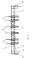
- Fig. 3 shows an apparatus 6 comprising three modules, namely a left end module 7, a right end module 9 and an intermediate module 8.
- Each module 7, 8, 9 is provided with two cramp stations 13. At the end modules 7 and 9 the cramp stations 13 closest to the ends of the apparatus 6 are mutually displaceable in the longitudinal direction of the apparatus so that the mutual distance of the cramp stations 13 in each end module 7, 9 can be varied whereby the distance from the outer cramp stations 13 to the ends of the apparatus can be varied.
- the length of the free ends of the reinforcing irons 4 at the sides of the rod mesh 3 can be varied.
- a gear box 11 with gear wheel 12 is arranged which is able to drive the rolling up of the rod mesh 3.
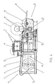
- Fig. 4 shows at the left side of the cramp station 13 a band roll 1 for a steel supporting band 2.
- the steel supporting band 2 can be drawn up to and along a cramp mounting block 14 forward to a rod mesh rolling up device 19.
- Above the cramp stations 13 is arranged a supporting beam 17 with a shelf 16 on which a bunch of rods of reinforcing iron 4 can be placed.
- a number of rods therefrom can be arranged in a magazine 15 immediately above the cramp mounting block 14.
- the connecting by cramps of reinforcing iron 4 to the steel supporting band 2 is carried out by a number of reinforcing irons 4 which are arranged transversely to the steel supporting band 2 being arranged on the supporting beam 17 of the cramp mounting block 14 and then cramped thereto. Thereafter the steel supporting band 2 is drawn forward a predetermined length of feed and connecting by cramps can continue or the net rolling up can be finished.
- the net rolling-up device 22 is shown to the right in Fig. 4 . It consists of a driving ring 18 being driven via a shaft from the gear wheel 12 and to which a front or outermost reinforcing iron 4 on the steel supporting band 2 of the rod mesh 3 has been attached, and around which the steel supporting band 2 with cramped reinforcing irons 4 is rolled up.
- the driving ring 18 may as shown follow upwards in accordance with the rolling up until a fully rolled up rod mesh 3 is achieved.
- a support 19 travelling with the outer circumference of the rod mesh, said support 19 may consist of two car rubber wheels 19.
- a chain wheel 23 with a friction hub being driven via a shaft from the gear box 11 may bring the car rubber wheel 19 closest to the band roll 1 in rotation clockwise or anticlockwise and may thus contribute to the rod mesh 2 being tightly wound up.
- a dispensing slide 21 along with the finished rod mesh 3 may roll when the following-on support 19 is lowered.
- the arrangement of the reinforcing iron 4 on steel supporting bands 2 can be made manually, partly automatic or fully-automatic.
- An embodiment for fully or partly automatic arrangement is shown in Fig. 5 .
- the upper sketch shows a magazine 15 and a supply device 30 for reinforcing iron to be arranged on the steel supporting band 4.
- the supply devices 30 are arranged between and outside the cramp stations 13 and are lifted when the rod mesh 3 is moved.
- the lower sketch shows a cramp station 13 where a cramp 5 from a cramp pistol 33 has been shot through the steel supporting band 2 against the inner wall form of a counter punch matrix 32 so that the two leg ends of the cramp 5 are brought into parallell extension tightly around the reinforcing iron 4 by the fastening.
- the counter punch matrix 32 is lifted while reinforcing irons 4 are arranged on the steel supporting band 2 and during the movement thereof.
- the apparatus is driven intermittently so that all parts are moved in mutual synchronism.
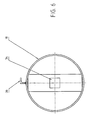
- Fig. 6 shows a driving ring 18 with a square hub hole 34 with one side a little larger than the cross section of a tubular driving shaft 28.
- a hook 35 is fastened to the circumference of the driving ring 18 to which a reinforcing iron 4 on the rod mesh 3 can be fastened, whereupon the rolling-up of the rod mesh 3 can be initiated with the point of the hook pointing in the rolling-up direction.
- Figs. 7 and 8 show the driving motor 24 of the gear box 11 and driving a friction hub 31.
- a chain or belt drive 29 therefrom drives a gear wheel 12 arranged on a hollow shaft 26 with a square driving hole 27 through which the tubular driving shaft 28 with the square cross section (cf. Fig. 9 ) for a driving ring 18 can be inserted.
- Fig. 9 shows a tubular driving shaft 28 with square cross section which is a little smaller than the cross section of the driving hole 27 in the gear wheel 12 and the cross section of the hub hole 34 in the driving ring 18.
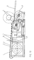
- Fig. 10 shows the cramp station 13 with lowered dispensing slide 21.
- the rod mesh 3 Before the rod mesh 3 is released from the net rolling device 22 and is guided to the dispensing slide 21 it should be fastened against unintended unrolling. This can be carried out by locking or winding it with wire or clips or providing it with hooklike locking means or the like.
- the driving rings 18 and cooperating auxiliary supporting rings arranged inside the rod mesh roll remain in the finished roll and may be returned to the manufacturer after the positioning of the rod mesh.
- the rod mesh 3 is guided to a rod mesh rolling device where the end forwarded from the steel supporting bands 2 synchronously are subject to a pulling force in the circumferential direction of at least two driving rings 18, said driving rings 18 are arranged practically coaxially as inner rod mesh rolling drive unit for the rod mesh 3 and having an outer diameter corresponding to the desired inner diameter for the rod mesh 3.
- Each of the driving rings 18 is supported by a support 19 following the circumference of the rod mesh 3 which supports the driving ring 18 during its rotation via the rod mesh 3 being rolled up.
- the following-on support 19 of the driving rings 18 may as mentioned take place by a couple of supporting wheels 19 arranged at mutual axial distance, such as car rubber wheels. Thus it is achieved that the full pulling force is exploited for tightening the rolling-up of the rod mesh.
- the outermost steel supporting bands 2 for the manufacture of the rod mesh 3 are each supported by a combined band guiding and cramping station 13 which is displaceably arranged in the transverse direction of the rod mesh 3 for adjustment of the predetermined protruding reinforcement iron end.
- a predetermined protruding length of the ends of the reinforcing irons at the sides of the rod mesh can be achieved.
- the rotation of the rod mesh 3 is locked preferably by each rotation stop during the manufacture of the rod mesh 3. Thus it is achieved that the tight rolling-up of the rod mesh is maintained.
- the rod mesh 3 which after the rolling-up is fastened to itself, e.g. by means of wire, is then as a finished unflexible roll guided downwards and is resting on the supporting wheels 19 by the lowering thereof, until the rod mesh roll 3 is delivered for the sliding or rolling down on at least two from the cramp station 13 downwardly inclining supporting rods 17 for delivery to a conveyor band, a trolley, in a transport container or a storage yard.
Landscapes
- Engineering & Computer Science (AREA)
- Architecture (AREA)
- Mechanical Engineering (AREA)
- Civil Engineering (AREA)
- Structural Engineering (AREA)
- Wire Processing (AREA)
- Reinforcement Elements For Buildings (AREA)
- Manufacturing Of Tubular Articles Or Embedded Moulded Articles (AREA)
- Sewage (AREA)
Abstract
Description
- The invention relates to a method for the manufacture of concrete reinforcing rod mesh comsisting of longitudinally extending steel supporting bands and transversely extending reinforcing irons being fastened to the steel supporting bands.
- By known methods and apparatuses a binding wire of soft irons are used, said wire being so flexible that it easily can be wound around reinforcing iron and steel supporting band and thus connect the two parts. The modest strength properties of the wire, however, causes a relatively loose and weak connection established between the reinforcing iron and the steel supporting wire. This results in a rod mesh in a loosely rolled-up form, similar to a loosely rolled-up carpet roll, which is quite flexible transversely to its longitudinal axis and thus difficult to handle during transport and during its positioning on the point of use.
- An apparatus having the same drawback is known from German utility model No.
DE 94 12 405 U1 . - For each connection the two leg ends of a clip (Halteclips, Drahtbügels, Montageclips, Befestigungsclips) are arranged from the upper side of a reinforcing iron with one leg on each side thereof and further through already punched holes in a supporting band and are fastened thereto when the intermediate body part of the clip extending between the two legs of the clip arranged at a distance from the sides of the reinforcing iron, has been arranged to rest against less than 180° of the upper side of the circumference of the reinforcing iron.
- It appears that the body part of the clip consisting of wire according to the utility model, cf.
Fig. 3 , with its intermediate part is pressing against less than 180° of the upper side of a reinforcing iron with a relatively low force which depends only on the bending forces exerted by the wire parts in body and legs of the clip. Thus, the reinforcing iron is not efficiently supported on its sides of the clip which thus with a correspondingly weak grip keeps the reinforcing iron in its position on the supporting band. This also results in a loosely rolled-up rod mesh which is relatively easily flexible transversely to its longitudinal axis and is thus difficult to handle during transport and during its positioning on the site of use. - It is the purpose of this invention to eliminate this drawback.
- According to the invention this is achieved by a method being characterized in that the fastening is made by pressing a U-shaped cramp - where the body part of the U is rectilinear - with its leg ends through the steel supporting band and tightly around the reinforcing iron, so that the cramp with its two leg ends preferably is brought to surround a part of the circumference of the reinforcing iron tightly from each side and with its body part to extend preferably in the longitudinal direction of the steel supporting band.
- Thus, a far more firm and strong connection between the steel supporting band and the reinforcing iron is achieved than by the known methods, since the cramp consists of an iron alloy with strength properties which causes articles such as rod mesh a far minor flexibility than with binding wire and makes a rolled up rod mesh far more rigid with the advantages resulting therefrom namely that the rod mesh roll will be less inclined to bend transversely to its longitudinal axis during transport and positioning.
- In a preferred embodiment of the method according to the invention the two leg ends of the cramp is guided by the inner wall shape of a counter punch matrix so that the two leg ends of the staple are caused side by side to extend parallelly and tightly around the reinforcing iron by the fastening, whereby the cramp preferably is dispensed from a staple pistol with cramp supply, which pistol is stationarily arranged at one side of the steel supporting band and is cooperating with the counter punch matrix arranged at the opposite side of the steel supporting band for attaching the reinforcing iron against the steel supporting band and the cramp pistol and for the guiding the cramp leg ends during the fastening operation.
- Thus is achieved relatively large contact surfaces between the cramp, the steel reinforcing band and the reinforcing iron and a resulting firm and strong connection between said parts.
- In a preferred embodiment of the method according to the invention the two leg ends of the cramp is guided by the inner wall shape of a counter punch matrix so that the two leg ends of the cramp are caused to extend parallelly tightly around the reinforcing iron by the fastening whereby each cramp is dispensed from a cramp pistol with cramp supply, said pistol being displaceably arranged along one side of the steel supporting band and cooperates with a counter punch matrix being displaceable along the opposite side of the steel supporting band for the attachment of the reinforcing iron against the steel supporting band and the cramp pistol and for guiding the cramp leg ends during the fastening operation.
- In a preferred embodiment of the method according to the invention the reinforcing irons are supplied from a magazine by a supply device to the side of the steel supporting band opposite the cramp pistol and each iron is attached against the steel supporting band and the cramp pistol by presure from the counter punch matrix until the cramp pistol has shot a cramp in place.
- Immediately thereupon the rod mesh can be advanced one length of feed and the next fastening operation can be carried out.
- The invention also relates to an apparatus for carrying out the method according to the invention, namely an apparatus for use by the manufacture of concrecte reinforcing rod mesh and comprising of in its longitudinal direction extending steel supporting bands and transversely extending reinforcing irons being fastened to the steel supporting irons.
- The apparatus according to the invention is characterized in that it has means for said fastening by cramp insertion operation and the fastening is adapted to take place by forcing or pressing a U-shaped cramp with a rectilinear body part with its leg ends through the steel supporting band and tightly around the reinforcing iron and with said body part extending preferably in the longitudinal direction of the steel supporting band. Thus, an apparatus for fulfilling the purpose of the method is achieved.
- The invention will now be described in more detail with reference to the drawing in which
-
Fig. 1 shows a side view of the manufacture of the rod mesh, -
Fig. 2 a top view of the manufacture of the rod mesh, -
Fig. 3 a top view of an embodiment of the apparatus, -
Fig. 4 a cross section in a cramp station with a dispensing slide in its position during the rolling up of the rod mesh, -
Fig. 5 an embodiment for total or partly automatized supply of reinforcing iron and a key sketch, from the top showing a magazine arranged above the cramp stations and a supply device for reinforcing irons, and from the bottom showing a cramp pistol and a counter punch matrix arranged on the opposite side of the band, -
Fig. 6 a driving ring around which the rod mesh should be rolled up, -
Fig. 7 an axial section of a gear box, -
Fig. 8 a gear box seen from the outer end and in an axial direction relatively to the apparatus, -
Fig. 9 a tube shaped driving shaft with square section, and -
Fig. 10 a cross section of a cramp station with a dispensing slide in its lowered position. - In
Figs. 1 and2 respectively aband roll 1 withsteel supporting band 2 is shown to the left, said roll passing acramp station 13 where the reinforcingirons 4 are fastened by cramps for forming arod mesh 3 shown in its rolled-up condition at the left side. -
Fig. 3 shows anapparatus 6 comprising three modules, namely aleft end module 7, a right end module 9 and anintermediate module 8. - Each
module cramp stations 13. At theend modules 7 and 9 thecramp stations 13 closest to the ends of theapparatus 6 are mutually displaceable in the longitudinal direction of the apparatus so that the mutual distance of thecramp stations 13 in eachend module 7, 9 can be varied whereby the distance from theouter cramp stations 13 to the ends of the apparatus can be varied. Thus it is achieved that the length of the free ends of the reinforcingirons 4 at the sides of therod mesh 3 can be varied. - At each end of the apparatus 6 a
gear box 11 withgear wheel 12 is arranged which is able to drive the rolling up of therod mesh 3. -
Fig. 4 shows at the left side of the cramp station 13 aband roll 1 for asteel supporting band 2. Thesteel supporting band 2 can be drawn up to and along acramp mounting block 14 forward to a rod mesh rolling updevice 19. Above thecramp stations 13 is arranged a supportingbeam 17 with ashelf 16 on which a bunch of rods of reinforcingiron 4 can be placed. A number of rods therefrom can be arranged in amagazine 15 immediately above thecramp mounting block 14. The connecting by cramps of reinforcingiron 4 to thesteel supporting band 2 is carried out by a number of reinforcingirons 4 which are arranged transversely to thesteel supporting band 2 being arranged on the supportingbeam 17 of thecramp mounting block 14 and then cramped thereto. Thereafter thesteel supporting band 2 is drawn forward a predetermined length of feed and connecting by cramps can continue or the net rolling up can be finished. - The net rolling-up
device 22 is shown to the right inFig. 4 . It consists of a drivingring 18 being driven via a shaft from thegear wheel 12 and to which a front or outermost reinforcingiron 4 on thesteel supporting band 2 of therod mesh 3 has been attached, and around which thesteel supporting band 2 with cramped reinforcingirons 4 is rolled up. The drivingring 18 may as shown follow upwards in accordance with the rolling up until a fully rolled uprod mesh 3 is achieved. During the rolling up thedriving ring 18 is supported during its rotation via therod mesh 3 by asupport 19 travelling with the outer circumference of the rod mesh, saidsupport 19 may consist of twocar rubber wheels 19. Achain wheel 23 with a friction hub being driven via a shaft from thegear box 11 may bring thecar rubber wheel 19 closest to theband roll 1 in rotation clockwise or anticlockwise and may thus contribute to therod mesh 2 being tightly wound up. At the following-onsupport 19 is arranged a dispensingslide 21 along with the finishedrod mesh 3 may roll when the following-onsupport 19 is lowered. - The arrangement of the reinforcing
iron 4 onsteel supporting bands 2 can be made manually, partly automatic or fully-automatic. An embodiment for fully or partly automatic arrangement is shown inFig. 5 . Here the upper sketch shows amagazine 15 and asupply device 30 for reinforcing iron to be arranged on thesteel supporting band 4. Thesupply devices 30 are arranged between and outside thecramp stations 13 and are lifted when therod mesh 3 is moved. The lower sketch shows acramp station 13 where acramp 5 from acramp pistol 33 has been shot through thesteel supporting band 2 against the inner wall form of acounter punch matrix 32 so that the two leg ends of thecramp 5 are brought into parallell extension tightly around the reinforcingiron 4 by the fastening. Thecounter punch matrix 32 is lifted while reinforcingirons 4 are arranged on thesteel supporting band 2 and during the movement thereof. The apparatus is driven intermittently so that all parts are moved in mutual synchronism. -
Fig. 6 shows adriving ring 18 with asquare hub hole 34 with one side a little larger than the cross section of atubular driving shaft 28. A hook 35 is fastened to the circumference of thedriving ring 18 to which a reinforcingiron 4 on therod mesh 3 can be fastened, whereupon the rolling-up of therod mesh 3 can be initiated with the point of the hook pointing in the rolling-up direction. -
Figs. 7 and8 show thedriving motor 24 of thegear box 11 and driving afriction hub 31. A chain orbelt drive 29 therefrom drives agear wheel 12 arranged on ahollow shaft 26 with asquare driving hole 27 through which thetubular driving shaft 28 with the square cross section (cf.Fig. 9 ) for adriving ring 18 can be inserted. -
Fig. 9 shows atubular driving shaft 28 with square cross section which is a little smaller than the cross section of thedriving hole 27 in thegear wheel 12 and the cross section of thehub hole 34 in thedriving ring 18. -
Fig. 10 shows thecramp station 13 with lowered dispensingslide 21. - Before the
rod mesh 3 is released from thenet rolling device 22 and is guided to the dispensingslide 21 it should be fastened against unintended unrolling. This can be carried out by locking or winding it with wire or clips or providing it with hooklike locking means or the like. The driving rings 18 and cooperating auxiliary supporting rings arranged inside the rod mesh roll remain in the finished roll and may be returned to the manufacturer after the positioning of the rod mesh. - By the manufacture the
rod mesh 3 is guided to a rod mesh rolling device where the end forwarded from thesteel supporting bands 2 synchronously are subject to a pulling force in the circumferential direction of at least two drivingrings 18, said driving rings 18 are arranged practically coaxially as inner rod mesh rolling drive unit for therod mesh 3 and having an outer diameter corresponding to the desired inner diameter for therod mesh 3. Each of the driving rings 18 is supported by asupport 19 following the circumference of therod mesh 3 which supports the drivingring 18 during its rotation via therod mesh 3 being rolled up. Thus it is achieved that the rod mesh during its rolling-up is not so inclined to bend across its longitudinal axis and therefore is easier to handle lateron. - The following-on
support 19 of the driving rings 18 may as mentioned take place by a couple of supportingwheels 19 arranged at mutual axial distance, such as car rubber wheels. Thus it is achieved that the full pulling force is exploited for tightening the rolling-up of the rod mesh. - The outermost
steel supporting bands 2 for the manufacture of therod mesh 3 are each supported by a combined band guiding and crampingstation 13 which is displaceably arranged in the transverse direction of therod mesh 3 for adjustment of the predetermined protruding reinforcement iron end. Thus, a predetermined protruding length of the ends of the reinforcing irons at the sides of the rod mesh can be achieved. - The rotation of the
rod mesh 3 is locked preferably by each rotation stop during the manufacture of therod mesh 3. Thus it is achieved that the tight rolling-up of the rod mesh is maintained. - The
rod mesh 3 which after the rolling-up is fastened to itself, e.g. by means of wire, is then as a finished unflexible roll guided downwards and is resting on the supportingwheels 19 by the lowering thereof, until therod mesh roll 3 is delivered for the sliding or rolling down on at least two from thecramp station 13 downwardly inclining supportingrods 17 for delivery to a conveyor band, a trolley, in a transport container or a storage yard. - The invention is not limited to the embodiments described in this application. Further embodiments are possible within the scope of the invention, which is defined by the appended claims.
Claims (5)
- Method for the manufacture of concrete reinforcing rod mesh (3) comprising of longitudinally extending steel supporting bands (2) and transversely extending reinforcing irons (4) being fastened to the steel supporting bands (2), characterized in that the fastening is made by pressing a U-shaped cramp (5) with a rectilinear body part with its leg ends through the steel supporting band (2) and tightly around the reinforcing iron (4), so that the cramp (5) with each of its leg ends is brought to surround a part of the circumference of the reinforcing iron (4) from each side and with its body part to extend preferably in the longitudinal direction of the steel supporting band.
- Method according to claim 1, characterized in that the two leg ends of the cramp (5) is guided by the inner wall shape of a counter punch matrix (32) so that the two leg ends of the cramp (5) side by side is brought to a parallell extension tightly around the reinforcing iron (4) by the fastening, whereby the cramp (5) preferably is dispensed from a cramp pistol (33) with a cramp supply, said pistol being arranged stationarily at one side of the steel supporting band (2) and cooperating with the counter punch matrix (32) at the opposite side of the steel supporting band (2) for attachment of the reinforcing iron (4) against the steel supporting band (2) and the cramp pistol (33) and for the guiding of the cramp leg ends during the fastening operation.
- Method according to claim 1, characterized in that the two leg ends of the cramp (5) is guided by the inner wall shape of a counter punch matrix (32) so that the two leg ends of the cramp (5) are brought to a parallell extension tightly around the reinforcing iron (4) by the fastening, whereby each cramp (5) is dispensed from a cramp pistol (33) with cramp supply, said pistol being arranged displaceably along the steel supporting band (2) at one band side and cooperating with a counter punch matrix (32) arranged at the opposite band side and also being displaceable along the band, said matrix being arranged for the attachment of the reinforcing iron (4) against the band and the cramp pistol (33) and for the guiding of the cramp leg ends during the fastening operation.
- Method according to any one of the preceding claims, characterized in that the reinforcing irons (4) are supplied from a magazine by a supply device (30) to the side of the steel supporting band (2) opposite the cramp pistol (33) and each iron is attached against the steel supporting band (2) and the cramp pistol (33) by a pressure from the counter punch matrix (32) until the cramp pistol has shot a cramp in place.
- Apparatus for use by the manufacture of concrete reinforcing rod mesh (3) comprising of longitudinally extending steel supporting bands (2) and transversely extending reinforcing irons (4) being fastened to the steel supporting bands (2), characterized in that it has means for said fastening by connecting by cramps, and the fastening is adapted to take place by forcing or pressing a U-shaped cramp (5), where the body part of the U is rectilinear, with its leg ends through the steel supporting band (2) and tightly around the reinforcing iron (4) and with said body part extending preferably in the longitudinal direction of the steel supporting band.
Applications Claiming Priority (3)
| Application Number | Priority Date | Filing Date | Title |
|---|---|---|---|
| DK200201129A DK176331B1 (en) | 2002-07-23 | 2002-07-23 | Method and machine for making the concrete reinforcement roller net |
| DK200201129 | 2002-07-23 | ||
| PCT/DK2003/000493 WO2004009266A1 (en) | 2002-07-23 | 2003-07-14 | Method and apparatus for the manufacture of concrete reinforcing rod mesh |
Publications (2)
| Publication Number | Publication Date |
|---|---|
| EP1539397A1 EP1539397A1 (en) | 2005-06-15 |
| EP1539397B1 true EP1539397B1 (en) | 2008-10-22 |
Family
ID=30470194
Family Applications (1)
| Application Number | Title | Priority Date | Filing Date |
|---|---|---|---|
| EP03764911A Expired - Lifetime EP1539397B1 (en) | 2002-07-23 | 2003-07-14 | Method and apparatus for the manufacture of concrete reinforcing rod mesh |
Country Status (6)
| Country | Link |
|---|---|
| EP (1) | EP1539397B1 (en) |
| AT (1) | ATE411858T1 (en) |
| AU (1) | AU2003244077A1 (en) |
| DE (1) | DE60324289D1 (en) |
| DK (2) | DK176331B1 (en) |
| WO (1) | WO2004009266A1 (en) |
Families Citing this family (5)
| Publication number | Priority date | Publication date | Assignee | Title |
|---|---|---|---|---|
| IT1392866B1 (en) | 2009-02-20 | 2012-04-02 | Schnell Spa | METHOD AND EQUIPMENT FOR REALIZING REINFORCED CONCRETE REINFORCEMENTS |
| WO2014117214A1 (en) * | 2013-02-01 | 2014-08-07 | Leonard Francis Beyers | Rebar mesh and method of production |
| CN109702120B (en) * | 2018-11-28 | 2024-01-26 | 建科机械(天津)股份有限公司 | Net welding machine |
| CN110560614B (en) * | 2019-09-25 | 2024-11-05 | 武汉易知鸟科技有限公司 | A flue rectangular wire mesh cage folding forming equipment |
| DE102020126584B3 (en) * | 2020-10-09 | 2021-12-30 | Bam Ag | Machine and process for the production of uniaxial steel wire mesh |
Family Cites Families (5)
| Publication number | Priority date | Publication date | Assignee | Title |
|---|---|---|---|---|
| GB1500665A (en) * | 1976-07-07 | 1978-02-08 | Hulek A | Process of manufacturing wrought-iron lattices |
| EP0122883A3 (en) * | 1983-04-15 | 1987-06-03 | MRK Marketing and Management Techniques (UK) Limited | Method of mechanically connecting the rods of a rod network, and apparatus for mechanically connecting the rods of a rod network |
| DE9412405U1 (en) * | 1994-04-13 | 1995-08-10 | Häussler, Wilhelm, Dipl.-Ing. Dipl.-Kaufm., 87629 Füssen | Reinforcement mat for reinforced concrete surface structures and machine for their production |
| JP3742938B2 (en) * | 1997-08-14 | 2006-02-08 | 清水建設株式会社 | Rebar unit assembly equipment |
| DE10126441A1 (en) * | 2000-07-08 | 2002-01-17 | Ekkehard Friedl | Reinforcement of crisscrossed rods joins rods by tie connectors having tie points both sides of rod using tie wire or cord. |
-
2002
- 2002-07-23 DK DK200201129A patent/DK176331B1/en not_active IP Right Cessation
-
2003
- 2003-07-14 AU AU2003244077A patent/AU2003244077A1/en not_active Abandoned
- 2003-07-14 AT AT03764911T patent/ATE411858T1/en not_active IP Right Cessation
- 2003-07-14 WO PCT/DK2003/000493 patent/WO2004009266A1/en not_active Ceased
- 2003-07-14 EP EP03764911A patent/EP1539397B1/en not_active Expired - Lifetime
- 2003-07-14 DK DK03764911T patent/DK1539397T3/en active
- 2003-07-14 DE DE60324289T patent/DE60324289D1/en not_active Expired - Lifetime
Also Published As
| Publication number | Publication date |
|---|---|
| DK1539397T3 (en) | 2008-12-15 |
| DE60324289D1 (en) | 2008-12-04 |
| ATE411858T1 (en) | 2008-11-15 |
| WO2004009266A1 (en) | 2004-01-29 |
| DK200201129A (en) | 2004-01-24 |
| AU2003244077A1 (en) | 2004-02-09 |
| EP1539397A1 (en) | 2005-06-15 |
| DK176331B1 (en) | 2007-08-13 |
Similar Documents
| Publication | Publication Date | Title |
|---|---|---|
| JP5356664B2 (en) | Method and apparatus for automatically binding reinforcing bars | |
| US20100294874A1 (en) | Winding device and method for fixing bundle or coil in the winding device | |
| US20030180098A1 (en) | Mobile system for manufacturing and installing reinforcing members | |
| EP1539397A1 (en) | Method and apparatus for the manufacture of concrete reinforcing rod mesh | |
| CN113458297A (en) | Automatic equipment of bundling of building site reinforcing bar | |
| JP6329260B2 (en) | Winder forming device | |
| KR101444344B1 (en) | Cable gripper, and cable laying device having the same | |
| KR101415719B1 (en) | Strapping Apparatus with integral tensioner | |
| US12589427B2 (en) | Method and apparatus for binding metal wires and similar products | |
| KR102587128B1 (en) | Hose packaging device with a structure consisting of multiple winders | |
| CN211707757U (en) | Easy-to-tighten strip steel rolling and flattening device | |
| KR19990037692A (en) | Binding devices for binding together extended objects | |
| CN209651643U (en) | A kind of measurement rope quickly retracting device | |
| KR101478768B1 (en) | A pipe concentration device | |
| CN220487162U (en) | Portable tectorial membrane maintenance instrument | |
| EP1565294B1 (en) | Method and apparatus for manufacturing an elongated product with a longitudinal and strenghtening reinforcement, and such a product | |
| EP3851617A1 (en) | Kit with mounting aid for transport anchors | |
| CN221615759U (en) | Mulch drip irrigation belt fixing device for seeding or turning of seeder | |
| EP1050502A2 (en) | Machine for coil rewinding having approached spiral coils | |
| CN211135344U (en) | Reinforcing steel bar straightening and transporting device for sleeper system | |
| GB2458326A (en) | Device for coiling a strap | |
| US3789651A (en) | Soft tube stretcher | |
| CN213083246U (en) | Civil engineering construction is with tubular product handling device of anticreep hand | |
| CN215977305U (en) | Metal mesh capable of being installed quickly | |
| CN211997283U (en) | Construction work surface garbage pickup device |
Legal Events
| Date | Code | Title | Description |
|---|---|---|---|
| PUAI | Public reference made under article 153(3) epc to a published international application that has entered the european phase |
Free format text: ORIGINAL CODE: 0009012 |
|
| 17P | Request for examination filed |
Effective date: 20050209 |
|
| AK | Designated contracting states |
Kind code of ref document: A1 Designated state(s): AT BE BG CH CY CZ DE DK EE ES FI FR GB GR HU IE IT LI LU MC NL PT RO SE SI SK TR |
|
| AX | Request for extension of the european patent |
Extension state: AL LT LV MK |
|
| DAX | Request for extension of the european patent (deleted) | ||
| GRAP | Despatch of communication of intention to grant a patent |
Free format text: ORIGINAL CODE: EPIDOSNIGR1 |
|
| RIC1 | Information provided on ipc code assigned before grant |
Ipc: B21F 27/08 20060101AFI20080430BHEP Ipc: E04C 5/04 20060101ALI20080430BHEP |
|
| GRAS | Grant fee paid |
Free format text: ORIGINAL CODE: EPIDOSNIGR3 |
|
| GRAA | (expected) grant |
Free format text: ORIGINAL CODE: 0009210 |
|
| AK | Designated contracting states |
Kind code of ref document: B1 Designated state(s): AT BE BG CH CY CZ DE DK EE ES FI FR GB GR HU IE IT LI LU MC NL PT RO SE SI SK TR |
|
| REG | Reference to a national code |
Ref country code: GB Ref legal event code: FG4D |
|
| REG | Reference to a national code |
Ref country code: CH Ref legal event code: EP |
|
| REG | Reference to a national code |
Ref country code: IE Ref legal event code: FG4D |
|
| REF | Corresponds to: |
Ref document number: 60324289 Country of ref document: DE Date of ref document: 20081204 Kind code of ref document: P |
|
| REG | Reference to a national code |
Ref country code: DK Ref legal event code: T3 |
|
| NLV1 | Nl: lapsed or annulled due to failure to fulfill the requirements of art. 29p and 29m of the patents act | ||
| PG25 | Lapsed in a contracting state [announced via postgrant information from national office to epo] |
Ref country code: AT Free format text: LAPSE BECAUSE OF FAILURE TO SUBMIT A TRANSLATION OF THE DESCRIPTION OR TO PAY THE FEE WITHIN THE PRESCRIBED TIME-LIMIT Effective date: 20081022 Ref country code: BG Free format text: LAPSE BECAUSE OF FAILURE TO SUBMIT A TRANSLATION OF THE DESCRIPTION OR TO PAY THE FEE WITHIN THE PRESCRIBED TIME-LIMIT Effective date: 20090122 Ref country code: ES Free format text: LAPSE BECAUSE OF FAILURE TO SUBMIT A TRANSLATION OF THE DESCRIPTION OR TO PAY THE FEE WITHIN THE PRESCRIBED TIME-LIMIT Effective date: 20090202 |
|
| PG25 | Lapsed in a contracting state [announced via postgrant information from national office to epo] |
Ref country code: FI Free format text: LAPSE BECAUSE OF FAILURE TO SUBMIT A TRANSLATION OF THE DESCRIPTION OR TO PAY THE FEE WITHIN THE PRESCRIBED TIME-LIMIT Effective date: 20081022 Ref country code: SI Free format text: LAPSE BECAUSE OF FAILURE TO SUBMIT A TRANSLATION OF THE DESCRIPTION OR TO PAY THE FEE WITHIN THE PRESCRIBED TIME-LIMIT Effective date: 20081022 Ref country code: PT Free format text: LAPSE BECAUSE OF FAILURE TO SUBMIT A TRANSLATION OF THE DESCRIPTION OR TO PAY THE FEE WITHIN THE PRESCRIBED TIME-LIMIT Effective date: 20090323 Ref country code: NL Free format text: LAPSE BECAUSE OF FAILURE TO SUBMIT A TRANSLATION OF THE DESCRIPTION OR TO PAY THE FEE WITHIN THE PRESCRIBED TIME-LIMIT Effective date: 20081022 |
|
| PG25 | Lapsed in a contracting state [announced via postgrant information from national office to epo] |
Ref country code: EE Free format text: LAPSE BECAUSE OF FAILURE TO SUBMIT A TRANSLATION OF THE DESCRIPTION OR TO PAY THE FEE WITHIN THE PRESCRIBED TIME-LIMIT Effective date: 20081022 Ref country code: RO Free format text: LAPSE BECAUSE OF FAILURE TO SUBMIT A TRANSLATION OF THE DESCRIPTION OR TO PAY THE FEE WITHIN THE PRESCRIBED TIME-LIMIT Effective date: 20081022 Ref country code: BE Free format text: LAPSE BECAUSE OF FAILURE TO SUBMIT A TRANSLATION OF THE DESCRIPTION OR TO PAY THE FEE WITHIN THE PRESCRIBED TIME-LIMIT Effective date: 20081022 |
|
| PLBE | No opposition filed within time limit |
Free format text: ORIGINAL CODE: 0009261 |
|
| STAA | Information on the status of an ep patent application or granted ep patent |
Free format text: STATUS: NO OPPOSITION FILED WITHIN TIME LIMIT |
|
| PG25 | Lapsed in a contracting state [announced via postgrant information from national office to epo] |
Ref country code: CZ Free format text: LAPSE BECAUSE OF FAILURE TO SUBMIT A TRANSLATION OF THE DESCRIPTION OR TO PAY THE FEE WITHIN THE PRESCRIBED TIME-LIMIT Effective date: 20081022 Ref country code: SE Free format text: LAPSE BECAUSE OF FAILURE TO SUBMIT A TRANSLATION OF THE DESCRIPTION OR TO PAY THE FEE WITHIN THE PRESCRIBED TIME-LIMIT Effective date: 20090122 Ref country code: IT Free format text: LAPSE BECAUSE OF FAILURE TO SUBMIT A TRANSLATION OF THE DESCRIPTION OR TO PAY THE FEE WITHIN THE PRESCRIBED TIME-LIMIT Effective date: 20081022 |
|
| 26N | No opposition filed |
Effective date: 20090723 |
|
| PG25 | Lapsed in a contracting state [announced via postgrant information from national office to epo] |
Ref country code: SK Free format text: LAPSE BECAUSE OF FAILURE TO SUBMIT A TRANSLATION OF THE DESCRIPTION OR TO PAY THE FEE WITHIN THE PRESCRIBED TIME-LIMIT Effective date: 20081022 |
|
| PG25 | Lapsed in a contracting state [announced via postgrant information from national office to epo] |
Ref country code: MC Free format text: LAPSE BECAUSE OF NON-PAYMENT OF DUE FEES Effective date: 20090731 |
|
| REG | Reference to a national code |
Ref country code: CH Ref legal event code: PL |
|
| GBPC | Gb: european patent ceased through non-payment of renewal fee |
Effective date: 20090714 |
|
| REG | Reference to a national code |
Ref country code: FR Ref legal event code: ST Effective date: 20100331 |
|
| REG | Reference to a national code |
Ref country code: IE Ref legal event code: MM4A |
|
| PG25 | Lapsed in a contracting state [announced via postgrant information from national office to epo] |
Ref country code: LI Free format text: LAPSE BECAUSE OF NON-PAYMENT OF DUE FEES Effective date: 20090731 Ref country code: CH Free format text: LAPSE BECAUSE OF NON-PAYMENT OF DUE FEES Effective date: 20090731 Ref country code: FR Free format text: LAPSE BECAUSE OF NON-PAYMENT OF DUE FEES Effective date: 20090731 |
|
| PG25 | Lapsed in a contracting state [announced via postgrant information from national office to epo] |
Ref country code: GB Free format text: LAPSE BECAUSE OF NON-PAYMENT OF DUE FEES Effective date: 20090714 |
|
| PG25 | Lapsed in a contracting state [announced via postgrant information from national office to epo] |
Ref country code: IE Free format text: LAPSE BECAUSE OF NON-PAYMENT OF DUE FEES Effective date: 20090714 |
|
| PG25 | Lapsed in a contracting state [announced via postgrant information from national office to epo] |
Ref country code: GR Free format text: LAPSE BECAUSE OF FAILURE TO SUBMIT A TRANSLATION OF THE DESCRIPTION OR TO PAY THE FEE WITHIN THE PRESCRIBED TIME-LIMIT Effective date: 20090123 |
|
| PG25 | Lapsed in a contracting state [announced via postgrant information from national office to epo] |
Ref country code: LU Free format text: LAPSE BECAUSE OF NON-PAYMENT OF DUE FEES Effective date: 20090714 |
|
| PG25 | Lapsed in a contracting state [announced via postgrant information from national office to epo] |
Ref country code: HU Free format text: LAPSE BECAUSE OF FAILURE TO SUBMIT A TRANSLATION OF THE DESCRIPTION OR TO PAY THE FEE WITHIN THE PRESCRIBED TIME-LIMIT Effective date: 20090423 |
|
| PG25 | Lapsed in a contracting state [announced via postgrant information from national office to epo] |
Ref country code: TR Free format text: LAPSE BECAUSE OF FAILURE TO SUBMIT A TRANSLATION OF THE DESCRIPTION OR TO PAY THE FEE WITHIN THE PRESCRIBED TIME-LIMIT Effective date: 20081022 |
|
| PG25 | Lapsed in a contracting state [announced via postgrant information from national office to epo] |
Ref country code: CY Free format text: LAPSE BECAUSE OF FAILURE TO SUBMIT A TRANSLATION OF THE DESCRIPTION OR TO PAY THE FEE WITHIN THE PRESCRIBED TIME-LIMIT Effective date: 20081022 |
|
| PGFP | Annual fee paid to national office [announced via postgrant information from national office to epo] |
Ref country code: DK Payment date: 20110727 Year of fee payment: 9 |
|
| PGFP | Annual fee paid to national office [announced via postgrant information from national office to epo] |
Ref country code: DE Payment date: 20120704 Year of fee payment: 10 |
|
| REG | Reference to a national code |
Ref country code: DK Ref legal event code: EBP |
|
| PG25 | Lapsed in a contracting state [announced via postgrant information from national office to epo] |
Ref country code: DK Free format text: LAPSE BECAUSE OF NON-PAYMENT OF DUE FEES Effective date: 20120731 |
|
| PG25 | Lapsed in a contracting state [announced via postgrant information from national office to epo] |
Ref country code: DE Free format text: LAPSE BECAUSE OF NON-PAYMENT OF DUE FEES Effective date: 20140201 |
|
| REG | Reference to a national code |
Ref country code: DE Ref legal event code: R119 Ref document number: 60324289 Country of ref document: DE Effective date: 20140201 |