EP1538727A2 - Bürstenlose elektrische Maschine - Google Patents
Bürstenlose elektrische Maschine Download PDFInfo
- Publication number
- EP1538727A2 EP1538727A2 EP04027397A EP04027397A EP1538727A2 EP 1538727 A2 EP1538727 A2 EP 1538727A2 EP 04027397 A EP04027397 A EP 04027397A EP 04027397 A EP04027397 A EP 04027397A EP 1538727 A2 EP1538727 A2 EP 1538727A2
- Authority
- EP
- European Patent Office
- Prior art keywords
- core
- core part
- electric machine
- teeth
- soft magnetic
- Prior art date
- Legal status (The legal status is an assumption and is not a legal conclusion. Google has not performed a legal analysis and makes no representation as to the accuracy of the status listed.)
- Withdrawn
Links
Images


Classifications
-
- H—ELECTRICITY
- H02—GENERATION; CONVERSION OR DISTRIBUTION OF ELECTRIC POWER
- H02K—DYNAMO-ELECTRIC MACHINES
- H02K1/00—Details of the magnetic circuit
- H02K1/02—Details of the magnetic circuit characterised by the magnetic material
-
- H—ELECTRICITY
- H02—GENERATION; CONVERSION OR DISTRIBUTION OF ELECTRIC POWER
- H02K—DYNAMO-ELECTRIC MACHINES
- H02K1/00—Details of the magnetic circuit
- H02K1/06—Details of the magnetic circuit characterised by the shape, form or construction
- H02K1/12—Stationary parts of the magnetic circuit
- H02K1/14—Stator cores with salient poles
- H02K1/146—Stator cores with salient poles consisting of a generally annular yoke with salient poles
- H02K1/148—Sectional cores
Definitions
- the invention relates to a brushless electric machine, which serves as a pancake with a Primary part and a secondary part is formed, wherein the primary part is a soft magnetic Core and a winding, wherein the soft magnetic core is a yoke region and associated teeth having pole pieces which are between the teeth overlap formed grooves, and wherein the secondary part permanent magnets with several in having a plane arranged poles.
- Such designed as an electric motor electric machine is known in practice. It has a stator as the primary part and a disk rotor as a secondary part.
- the stator points a wound from a soft magnetic sheet metal strip ring band core, in the radial Direction has several superimposed metal layers.
- To reduce eddy current losses is the sheet metal strip on one of its flat sides with an electrically insulating Coating provided which the individual sheet metal layers in the radial direction electrically isolated against each other.
- the ring band core has at its the disk rotor facing Flat side extending radially to the axis of rotation of the electric motor extending grooves, in which a Winding is arranged. Teeth are formed between the grooves on both sides of the grooves Pole shoes have, which partially cover the groove space.
- a slot slot is formed in each case, through which the pole pieces from each other are spaced.
- the toroidal core first the areas in which later the grooves and the slot slots are arranged from the first still about punched out stiffened sheet metal strip. Doing so, the distance between the in the band introduced punching holes, starting from the end of the metal strip, the later the inside of the toroidal core is disposed to the opposite other end the metal strip according to the increase in the diameter at which the punched openings are arranged after winding of the toroidal core, continuously increased, in such a way that the punched openings associated with a groove after winding the ring band core in Radial alignment with each other.
- the soft magnetic core a first, at least the yoke portion having core part and a second connected thereto, at least the Polschuh having core part has that the first core part formed as a ring band core is, and that the second core part is formed as a shaped body, the soft magnetic particles contains, between which an electrically insulating material is arranged.
- the soft magnetic core is composed as at least two parts, namely the ring band core and the soft magnetic molding.
- the soft magnetic core Due to the soft magnetic molded body, the soft magnetic core in Produce mass production cost-effectively with small pole pitch and compact dimensions. Due to the small pole pitch of the soft magnetic core in the axial direction a short Have length.
- the electric machine according to the invention thereby enables a flat design.
- the magnetic resistance in the magnetic circuit is opposite to a soft magnetic Core, which consists entirely of crystalline iron, by the soft magnesian Shaped body only slightly increased.
- the electric machine according to the invention allows a high power density and low magnet costs.
- the winding coils of the winding can be wound directly onto the teeth. Preferably, however, they are wound up as forming coils on a separate bobbin, withdrawn from this and then plugged as a finished winding coils on the teeth. Thereafter, the core parts are joined together. The assembly of the electrical Machine is thereby additionally simplified.
- the second core part is as Eisenpulverpressteil formed, which has iron powder particles, with the electrically insulating Material are coated.
- a Eisenpulverpressteil can with the help of a corresponding Forming tool under the action of heat and pressure from iron powder particles are prepared, which are provided with an electrically insulating coating, preferably an iron oxide layer.
- the iron powder particles become too a form-stable molded body baked together.
- the coating of the iron powder particles remains largely preserved, so that they continue at least partially electrically isolated from each other. Eddy current losses in the iron powder compact thereby largely avoided.
- the second core part is as Injection molded part formed embedded in an electrically insulating plastic compound having soft magnetic particles.
- the soft magnetic particles which are preferably are formed as iron powder grains, fixed by the surrounding plastic mass connected with each other.
- the second core part is designed as a preferably annular disc, the approximately parallel to the plane of extension of the secondary part between this and the first Core part is arranged.
- the pole pieces of the individual teeth of the soft magnetic core are integrally connected with each other, which in the manufacture of the electric machine allows easy assembly of the core parts of the soft magnetic core.
- each of a groove associated Pole shoes arranged on both sides of the respective groove teeth at their facing each other End portions integrally connected to each other, wherein the second core part at its the secondary part facing away in the region of these pole pieces one recess each has, on which the wall thickness of the second core part in each case in the circumferential direction decreases from the edge of the groove to the end of the pole piece spaced therefrom.
- the recesses are grooved preferably formed with wedge-shaped slopes and extend approximately parallel to the teeth.
- the wall thickness of the second core part along the recesses in each case starting from the radially inner to the radially outer end of the recesses decreases. Thereby an even greater mechanical strength of the second Kemteils can be achieved.
- the in the region of the radially inner end of the individual wells because of the larger there axial wall thickness of the second core part increased magnetic leakage flux between each other adjacent adjacent teeth is at least partially compensated by at constant groove width and constant wall thickness of the second core part the magnetic flux density in the pole shoes with decreasing distance to the axis of rotation of the electric machine increases, i. at the radially inner end of the recesses is the magnetic flux density greater than at the radially outer end of the wells.
- the groove-shaped depressions of second core part with a solidified potting compound of low magnetic permeability filled This allows an even greater mechanical stability and a correspondingly reduced Risk of breakage of the second core part can be achieved.
- the potting compound is preferably immediately after the pressing or injection molding of the second core part with open Forming tool filled in liquid or pulpy form in the wells. After this Solidifying the potting compound, the second core part is removed from the mold.
- the teeth are in each case arranged completely on the second core part and when the toroidal core is not grooved and facing the pole pieces at its end Flat side is connected to the remote from the pole pieces ends of the teeth.
- Disc rotor or axial flux machine trained electrical machine is special inexpensive to produce.
- the second core part is preferably pressed in one manufactured two-stage tool, wherein in a first stage, a first punch the compacted thin-slot groove slot areas and after filling additional iron powder a second punch densifies the tooth areas.
- refilling the Iron powder can be dispensed with, if the two punches from different sides the Compact iron powder.
- portions of the teeth are integral with formed the yoke region, including the first core part facing at its the secondary part Flat side has grooves between which the sections are formed. In the magnetic circuit then results in an even lower magnetic resistance.
- the grooves are preferred by laser erosion and larger ring band cores incorporated by band punching in the iron band of the ring band core.
- the second core part between circumferentially adjacent to each other Wells each having at least one interruption, and if the one piece formed with the yoke portion portions of the teeth with their free ends in the interruptions intervention.
- the core parts of the soft magnetic core are then form-fitting connected with each other.
- the pole shoes assigned to the individual grooves are each connected by a Groove slot are spaced apart, and if the pole pieces preferably at the radial inner and / or outer edge of the second core part by at least one transverse web are integrally connected to each other. Through the slot slots results between each other adjacent pole shoes of different teeth an even lower magnetic leakage flux. Nevertheless, the pole pieces are integral with each other by the at least one transverse web connected, which allows easy mounting of the pole pieces on the first core part.
- the transverse web is preferably of annular design and on the inner in the radial direction Edge of the second core part arranged because there the magnetic flux density at a electric machine with a constant groove width is greater than at the outer edge of the second Core part.
- the at least one transverse web advantageously has long fibers as reinforcement.
- the second core part preferably formed as laminated cores soft magnetic metal inserts, preferably with the soft magnetic particles and the electrically insulating located between them Material are sheathed.
- the soft magnetic core then has an even smaller magnetic Resistance on.
- the metal inserts increase the mechanical stability of the second core part.
- the soft magnetic sheet metal inserts containing electrically insulating Material can be applied by means of an injection molding process on the laminated cores become.
- the second core part has exact dimensions. The sheet metal inserts can be inserted in the mold during pressing or spraying of the second core part be so that they in the pressing or injection process with the soft magnetic Particles and located between them electrically insulating material existing Injection molding material are sheathed.
- the metal strips preferably have an edge ratio, which is a transport as bulk material and the subsequent separation allowed in an automatic assembly machine.
- the sheet metal strips are punched out of a grain-oriented sheet metal strip, the is rolled diagonally before punching.
- the metal strips thereby have a wedge shape, the singulation facilitates their alignment.
- To align the wedge segmented Sheet metal strips fall into a gap of a separating plant that is larger than the small one Dimension of the metal strips, but smaller than their large size. Both sides of the Slits can be moved back and forth to exploit the metal strips Align gravity.
- the metal strips get on Conveyor belt, in which a permanent magnetic film is incorporated, which is a change in position of the Prevents metal strips. If necessary, misaligned metal strips with the help an optical control device recognized, separated and then the separation plant be fed again. Carefully arranged metal strips get into a holder, from which they take grippers of a placement machine.
- the mold for manufacturing of the soft magnetic molding is at high speed with the metal strip equipped, wherein the metal strip in the circumferential direction of the mold cavity of the mold layered and held by a gripping at its radial ends while being with the of the soft magnetic particles and the electrically insulating Material existing mass to be encapsulated.
- the radial ends of the laminated cores are molded only on the air gap side and on their front sides. So they can in the Forming tool to be fixed.
- the potting material may be a casting resin.
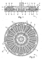
- a designated as a whole in Fig. 1 with 1, designed as a pancake brushless Electric machine has a primary part 2 and a secondary part 3.
- the trained as a stator Primary part 2 has a soft magnetic core having a polyphase winding.
- 4 carries, which connectable to generate a traveling magnetic field with a three-phase power source is.
- the soft magnetic core has teeth 5 which each take a winding coil of the winding 4.
- the teeth 5 are by a in the indicated by the double arrow Pf circumferential direction annular circumferential yoke area of the soft magnetic core interconnected.
- the soft magnetic core and the Winding 4 are arranged in the inner cavity of a housing pot 6.
- Fig. 1 can be seen the yoke region of the soft magnetic core facing away from the winding 4 Rear surface abuts the bottom of the housing pot 6.
- the secondary part 3 is an approximately disc-shaped rotor part. 7 having, via a designed as a four-point bearing roller bearing 8 rotatably mounted on the Housing pot 6 is mounted.
- the housing pot 6 has for this purpose at its bottom approximately centrally Recording on, in which the roller bearing 8 is inserted.
- An outer bearing of the rolling bearing 8 is due to the inclusion of the housing pot 6 and an inner bearing of the roller bearing 8 at a portion of a connected to the rotor part 7 shaft 9 at.
- Fig. 1 is further seen that at the soft magnetic core facing Flat side of the rotor part 7 a plurality of permanent magnets 10 are arranged, which in the circumferential direction Pf in turn alternately form magnetic north and south poles, which over a located between the permanent magnet 10 and the soft magnetic core Air gap 11 with the magnetic traveling field of the winding 4 for generating a rotational movement of the rotor part 7 cooperate.
- the permanent magnets 10 can in radial Have direction overhang over the soft magnetic core, i. they stand behind inside or outside over this over.
- the grooves 13 in radial Direction a constant cross section.
- the cross section of Grooves 13 in an electric machine with bar winding in the radial direction from the inside increases towards the outside.
- the cross section of the winding bars then takes in appropriate Way in the radial direction from the inside out towards.
- the soft magnetic core has a first, at least the yoke portion having core part 14 and an associated second, at least the pole pieces 12 having core part 15.
- the first core part 14 is formed as a ring band core of a soft magnetic sheet metal strip.
- the ring band core has several superposed in the radial direction, in the Drawing not shown soft magnetic layers through sections of the Sheet metal bands are formed. Between adjacent layers is for reduction the caused by the magnetic traveling field in the toroidal core eddy current losses each arranged a thin insulating layer, for example, a silicon dioxide layer can be.
- the second core part 15 is formed as a shaped body, the soft magnetic particles contains, between which an electrically insulating material is arranged.
- the second core part is formed as a Eisenpulverpressteil, contains the iron powder particles coated with the electrically insulating material are.
- an iron powder is provided whose particles or grains have on their surface an electrically insulating coating.
- the iron powder is then filled into the inner cavity of a mold in which it is under Heat is injected into the shaped body in such a way that the particles form-fit connected to each other.
- the coating of the iron powder particles remains largely preserved, so that the particles continue to at least partially through the coating are electrically isolated from each other. Eddy current losses in the iron powder compact are avoided as far as possible.
- the second core part 15 is an injection-molded part formed, which contains a plurality of soft magnetic particles, which in an electrically insulating plastic compound are embedded.
- a core part 15 can be mass produced be produced inexpensively using a mold in injection molding.
- the dimensions of the soft magnetic particles are chosen such that they together with the plastic compound in the liquid state by means of a spray nozzle in the mold can be injected. After solidification and / or curing of Plastic compound holds these soft magnetic particles together.
- the second core part 15 is formed as an annular disc is. This is approximately parallel to the plane of extension of the secondary part 3 between this and arranged the first core part 14.
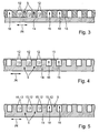
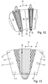
- the individual grooves 13 are each associated pole pieces 12 of both sides of the grooves 13 arranged teeth 5 at their each other facing end portions integrally connected to each other. It takes the axial Wall thickness of the pole pieces 12, each in the circumferential direction Pf starting from the edge of the groove 13 from the center of the groove 13 down. It can clearly be seen that this is achieved by the one pole 13 respectively associated pole pieces 12 on its groove 13 side facing Have wedge slopes, the depressions 16 form. In FIGS. 6 and 7 it can be seen that these recesses 16 extend in the radial direction.
- the teeth 5 are completely on the second core part 15 is arranged.
- the first core part 14 formed by the toroidal core is formed ungeutet and on its outer circumference in each case with the surface of the pole pieces 12 distal ends of the teeth 5 connected.
- the ring band core is therefore special inexpensive to produce.
- portions of the teeth 5 are integral with the first core part 14 is formed.
- the first core part 14 has at its the secondary part third facing flat side portions of the teeth 5 on. It is clearly recognizable that the Secondary part 3 facing end portions of the teeth 5 with the pole pieces arranged thereon 12 is formed by the second core part 15. This extends in the circumferential direction Pf uninterrupted both over the grooves 13 and arranged on the first core member 14 Sections of the teeth 5.
- the second core part 15 has one of the number of teeth. 5 corresponding number of integrally interconnected segments, in the cross-sectional plane 4 are each formed approximately trapezoidal.
- the second core part 15 between in Circumferential direction Pf mutually adjacent recesses 16 each have an interruption or a breakthrough on.
- the openings extend in the radial direction over each the entire length of the teeth 5.
- the arranged on the first core part 14 sections of Teeth 5 are compared to the embodiment of FIG. 4 in a normal to the plane of extension of the first core portion 14 arranged direction extends to the air gap 11 and engage with their the secondary part 3 facing free end portions each in a form-fitting manner in a breakthrough of the second core part 15 a.
- the at the first core part 14th arranged portions of the teeth 5 each have an approximately rectangular cross-section.
- the free end portions of the teeth 5 are flat with their respective assigned Pole shoes 12 of the second core part 15 connected.
- the the secondary part 3 facing Bound surfaces of the arranged on the first core portion 14 portions of the teeth. 5 close each in the circumferential direction Pf in straight extension to the adjacent thereto, the secondary part 3 facing boundary surfaces of the pole pieces.
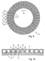
- Fig. 7 it can be seen that the pole pieces 12 by transverse webs 17 integral with each other are connected, which are arranged on the radially inner and outer edges of the second core part 15 are and circumferentially Pf circulate.
- the transverse webs 17 may also be arranged only at the inner edge of the second core part 15. At the radial outer ends of the pole pieces 12 are in this embodiment, no transverse webs 17th intended.
- FIGS. 9 and 10 is between the pole pieces 12 of individual grooves 13 each have a slot slot 18 arranged in the radial direction respectively along the entire length of its associated groove 13 extends. Similar to the Embodiment of Fig. 3 is also here the volume of the teeth 5 completely in the second core part arranged.
- the second Kemteil 15 as Sheet metal packages formed sheet metal deposits 19, with an electrically insulating plastic are encapsulated embedded in a variety of powdered soft magnetic particles are, which are not shown in detail in the drawing.
- the metal inserts 19 each have a plurality of metal layers 20, which are approximately radially to Rotation axis of the shaft 9 and 9 extend in the axial direction of the shaft. Between the in the circumferential direction adjacent sheet metal layers 20 of the individual sheet metal inserts 19 is each arranged a thin electrically insulating layer, which is used as a surface coating can be applied to the metal layers 20.
- the sheet metal inserts 19 starting from her inner, the shaft 9 facing end to its outer, the shaft 9 facing away End in the circumferential direction on an approximately constant wall thickness.
- the wall thickness of the sheet metal inserts 19, starting from their inner increases towards its outer end.
- a strong magnetic field through the Area of the teeth 5 passed.
- the soft magnetic particles in the plastic pulled into the tooth area and aligned there in their preferred direction.
- the concentration of soft magnetic particles in the circumferential direction from the edge of the groove 13 to the center line of the groove 13 down. This reduces the leakage flux in this area.
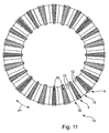
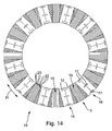
- FIGS. 11 to 14 are the individual grooves 13th respectively associated pole pieces 12 of the both sides of the grooves 13 arranged teeth 5 at their mutually facing end portions integrally connected to each other. It takes the axial wall thickness of the pole pieces 12, each in the circumferential direction Pf starting from the edge of Groove 13 to one of the edges of the groove 13 spaced, befindichen between the edges Place the groove 13 down.
- Figs. 13 and 14 are mutually adjacent pole pieces 12 each by a plurality, radially to the axis of rotation of the Shaft 9 spaced apart, extending in the circumferential direction transverse webs 17 with each other connected.
- the invention is particularly suitable for axial flow machines small outer diameter and deep grooves (> 2 mm) is suitable.
Landscapes
- Engineering & Computer Science (AREA)
- Power Engineering (AREA)
- Iron Core Of Rotating Electric Machines (AREA)
- Brushless Motors (AREA)
Abstract
Description
- 1
- elektrische Maschine
- 2
- Primärteil
- 3
- Sekundärteil
- 4
- Wicklung
- 5
- Zahn
- 6
- Gehäusetopf
- 7
- Rotorteil
- 8
- Wälzlagerung
- 9
- Welle
- 10
- Permanentmagnet
- 11
- Luftspalt
- 12
- Polschuh
- 13
- Nut
- 14
- erstes Kernteil
- 15
- zweites Kernteil
- 16
- Vertiefung
- 17
- Quersteg
- 18
- Nutschlitz
- 19
- Blecheinlage
- 20
- Blechschicht
- Pf
- Umfangsrichtung
Claims (14)
- Bürstenlose elektrische Maschine (1), die als Scheibenläufer mit einem Primärteil (2) und einem Sekundärteil (3) ausgebildet ist, wobei das Primärteil (2) einen weichmagnetischen Kern und eine Wicklung (4) aufweist, wobei der weichmagnetische Kern einen Jochbereich und damit verbundene Zähne (5) hat, die Polschuhe (12) aufweisen, welche zwischen den Zähnen (5) gebildete Nuten (13) überdecken, und wobei das Sekundärteil (3) Permanentmagnete (10) mit mehreren in einer Ebene angeordneten Polen aufweist, dadurch gekennzeichnet, dass der weichmagnetische Kern ein erstes, zumindest den Jochbereich aufweisendes Kernteil (14) und ein damit verbundenes zweites, zumindest die Polschuhe (12) aufweisendes Kernteil (15) hat, dass das erste Kernteil (14) als Ringbandkern ausgebildet ist, und dass das zweite Kernteil (15) als Formkörper ausgebildet ist, der weichmagnetische Partikel enthält, zwischen denen ein elektrisch isolierender Werkstoff angeordnet ist.
- Bürstenlose elektrische Maschine (1) nach Anspruch 1, dadurch gekennzeichnet, dass das zweite Kernteil (15) als Eisenpulverpressteil ausgebildet ist, das Eisenpulver-Partikel aufweist, die mit dem elektrisch isolierenden Werkstoff beschichtet sind.
- Bürstenlose elektrische Maschine (1) nach Anspruch 2, dadurch gekennzeichnet, dass das zweite Kernteil (15) als Spritzgussteil ausgebildet ist, das in eine elektrisch isolierende Kunststoffmasse eingebettete, weichmagnetischen Partikel aufweist.
- Bürstenlose elektrische Maschine (1) nach einem der Ansprüche 1 bis 3, dadurch gekennzeichnet, dass das zweite Kernteil (15) als vorzugsweise ringförmige Scheibe ausgebildet ist, die etwa parallel zur Erstreckungsebene des Sekundärteils (3) zwischen diesem und dem ersten Kernteil (14) angeordnet ist.
- Bürstenlose elektrische Maschine (1) nach einem der Ansprüche 1 bis 4, dadurch gekennzeichnet, dass die einer Nut (13) jeweils zugeordneten Polschuhe (12) der beidseits der betreffenden Nut (13) angeordneten Zähne (5) an ihren einander zugewandten Endbereichen einstückig miteinander verbunden sind, und dass das zweite Kemteil (15) an seiner dem Sekundärteil (3) abgewandten Seite im Bereich dieser Polschuhe (12) jeweils eine Vertiefung (16) aufweist, an der die Wandstärke des zweiten Kernteils (15) jeweils in Umfangsrichtung (Pf) ausgehend vom Rand der Nut (13) zu dem davon beabstandeten Ende des Polschuhs (12) hin abnimmt.
- Bürstenlose elektrische Maschine (1) nach einem der Ansprüche 1 bis 5, dadurch gekennzeichnet, dass die Vertiefungen (16) rillenförmig vorzugsweise mit keilförmigen Schrägen ausgebildet sind und etwa parallel zu den Zähnen (5) verlaufen.
- Bürstenlose elektrische Maschine (1) nach einem der Ansprüche 1 bis 6, dadurch gekennzeichnet, dass die Wandstärke des zweiten Kernteils (15) entlang der Vertiefungen (16) jeweils ausgehend vom radial inneren zum radial äußeren Ende der Vertiefungen (16) hin abnimmt.
- Bürstenlose elektrische Maschine (1) nach einem der Ansprüche 1 bis 7, dadurch gekennzeichnet, dass die rillenförmigen Vertiefungen (16) des zweiten Kernteils (15) mit einer verfestigten Vergussmasse geringer magnetischer Permeabilität befüllt sind.
- Bürstenlose elektrische Maschine (1) nach einem der Ansprüche 1 bis 8, dadurch gekennzeichnet, dass die Zähne (5) jeweils vollständig an dem zweiten Kernteil (15) angeordnet sind und dass der Ringbandkern ungenutet ist und an seiner den Polschuhen (12) zugewandten Flachseite mit den von den Polschuhen (12) entfernten Enden der Zähne (5) verbunden ist.
- Bürstenlose elektrische Maschine (1) nach einem der Ansprüche 1 bis 9, dadurch gekennzeichnet, dass Teilbereiche der Zähne (5) einstückig mit dem Jochbereich ausgebildet sind, und dass das erste Kernteil dazu an seiner dem Sekundärteil (3) zugewandten Flachseite Nuten (13) aufweist, zwischen denen diese Teilbereiche gebildet sind.
- Bürstenlose elektrische Maschine (1) nach einem der Ansprüche 1 bis 10, dadurch gekennzeichnet, dass das zweite Kernteil (15) zwischen in Umfangsrichtung (Pf) zueinander benachbarten Vertiefungen (16) jeweils mindestens eine Unterbrechung aufweist, und dass die einstückig mit dem Jochbereich ausgebildeten Teilbereiche der Zähne (5) mit ihren freien Enden in die Unterbrechungen eingreifen.
- Bürstenlose elektrische Maschine (1) nach einem der Ansprüche 1 bis 11, dadurch gekennzeichnet, dass die den einzelnen Nuten (13) zugeordneten Polschuhe (12) jeweils durch einen Nutschlitz voneinander beabstandet sind, und dass die Polschuhe (12) vorzugsweise am radial inneren und/oder äußeren Rand des zweiten Kernteils (15) durch wenigstens einen Quersteg einstückig miteinander verbunden sind.
- Bürstenlose elektrische Maschine (1) nach einem der Ansprüche 1 bis 12, dadurch gekennzeichnet, dass das zweite Kernteil (15) vorzugsweise als Blechpakete ausgabildete weichmagnetische Blecheinlagen (19) aufweist, die vorzugsweise mit den weichmagnetischen Partikeln und dem zwischen ihnen befindlichen elektrisch isolierenden Werkstoff ummantelt sind.
- Bürstenlose elektrische Maschine (1) nach einem der Ansprüche 1 bis 13, dadurch gekennzeichnet, dass die Nuten (18) mit einem elektrisch und magnetisch isolierenden, verfestigten Vergusswerkstoff befüllt sind, der die Kernteile (14, 15) und die Wicklung (4) fest miteinander verbindet.
Applications Claiming Priority (2)
| Application Number | Priority Date | Filing Date | Title |
|---|---|---|---|
| DE10357167 | 2003-12-06 | ||
| DE10357167 | 2003-12-06 |
Publications (2)
| Publication Number | Publication Date |
|---|---|
| EP1538727A2 true EP1538727A2 (de) | 2005-06-08 |
| EP1538727A3 EP1538727A3 (de) | 2006-04-12 |
Family
ID=34442489
Family Applications (1)
| Application Number | Title | Priority Date | Filing Date |
|---|---|---|---|
| EP04027397A Withdrawn EP1538727A3 (de) | 2003-12-06 | 2004-11-18 | Bürstenlose elektrische Maschine |
Country Status (2)
| Country | Link |
|---|---|
| EP (1) | EP1538727A3 (de) |
| DE (1) | DE102004055578A1 (de) |
Cited By (8)
| Publication number | Priority date | Publication date | Assignee | Title |
|---|---|---|---|---|
| CN105453396A (zh) * | 2013-06-21 | 2016-03-30 | 阿图罗·佩雷斯-罗德里格斯 | 旋转磁场机器的改进 |
| DE102017204431A1 (de) * | 2017-03-16 | 2018-09-20 | Brose Fahrzeugteile GmbH & Co. Kommanditgesellschaft, Würzburg | Antriebsvorrichtung zum Verstellen eines Abdeckelements |
| CN111725908A (zh) * | 2019-03-19 | 2020-09-29 | 上海盘毂动力科技股份有限公司 | 一种定子组件以及轴向磁场电机 |
| DE102020101149A1 (de) * | 2019-12-04 | 2021-06-10 | Schaeffler Technologies AG & Co. KG | Axialflussmaschine mit mechanisch fixierten Statorkernen mit radial verlaufenden Blechsegmenten |
| WO2021110198A1 (de) * | 2019-12-04 | 2021-06-10 | Schaeffler Technologies AG & Co. KG | Axialflussmaschine mit radial verlaufende blechsegmente aufweisendem stator |
| CN113939972A (zh) * | 2019-07-09 | 2022-01-14 | 米巴烧结奥地利有限公司 | 用于轴流机的定子 |
| WO2022127971A1 (de) | 2020-12-16 | 2022-06-23 | Schaeffler Technologies AG & Co. KG | Statorkern für axial-fluss-maschine in h-ausführung |
| DE102020133677A1 (de) | 2020-12-16 | 2022-06-23 | Schaeffler Technologies AG & Co. KG | Kühlkonzept für eine Axial-Fluss-Maschine in H-Ausführung |
Families Citing this family (4)
| Publication number | Priority date | Publication date | Assignee | Title |
|---|---|---|---|---|
| DE102016105510A1 (de) * | 2016-03-23 | 2017-09-28 | Hanning Elektro-Werke Gmbh & Co. Kg | Statorbaugruppe |
| AT522711A1 (de) * | 2019-07-09 | 2021-01-15 | Miba Sinter Austria Gmbh | Stator für eine Axialflussmaschine |
| DE102019118633A1 (de) * | 2019-07-10 | 2021-01-14 | Ziehl-Abegg Se | Statorkörper für eine elektrische Maschine |
| DE102021132325A1 (de) * | 2021-12-08 | 2023-06-15 | Schaeffler Technologies AG & Co. KG | Stator für eine axialflussmaschine |
Family Cites Families (5)
| Publication number | Priority date | Publication date | Assignee | Title |
|---|---|---|---|---|
| US4255684A (en) * | 1979-08-03 | 1981-03-10 | Mischler William R | Laminated motor stator structure with molded composite pole pieces |
| US5742450A (en) * | 1995-03-08 | 1998-04-21 | International Business Machines Corporation | Disk drive spindle motor with radial gap and field generating coils interconnected by ring flux guide |
| JP2003079120A (ja) * | 2001-09-03 | 2003-03-14 | Asmo Co Ltd | モータ用コア及び直流モータ |
| US6707221B2 (en) * | 2002-04-08 | 2004-03-16 | General Electric Company | Axial flux machine, stator and fabrication method |
| JP2003309944A (ja) * | 2002-04-11 | 2003-10-31 | Toyoda Mach Works Ltd | モータおよびインシュレータの製造方法 |
-
2004
- 2004-11-18 DE DE102004055578A patent/DE102004055578A1/de not_active Withdrawn
- 2004-11-18 EP EP04027397A patent/EP1538727A3/de not_active Withdrawn
Cited By (13)
| Publication number | Priority date | Publication date | Assignee | Title |
|---|---|---|---|---|
| CN105453396A (zh) * | 2013-06-21 | 2016-03-30 | 阿图罗·佩雷斯-罗德里格斯 | 旋转磁场机器的改进 |
| DE102017204431A1 (de) * | 2017-03-16 | 2018-09-20 | Brose Fahrzeugteile GmbH & Co. Kommanditgesellschaft, Würzburg | Antriebsvorrichtung zum Verstellen eines Abdeckelements |
| CN111725908A (zh) * | 2019-03-19 | 2020-09-29 | 上海盘毂动力科技股份有限公司 | 一种定子组件以及轴向磁场电机 |
| CN113939972A (zh) * | 2019-07-09 | 2022-01-14 | 米巴烧结奥地利有限公司 | 用于轴流机的定子 |
| DE102020101149A1 (de) * | 2019-12-04 | 2021-06-10 | Schaeffler Technologies AG & Co. KG | Axialflussmaschine mit mechanisch fixierten Statorkernen mit radial verlaufenden Blechsegmenten |
| DE102020101148A1 (de) * | 2019-12-04 | 2021-06-10 | Schaeffler Technologies AG & Co. KG | Axialflussmaschine mit radial verlaufende Blechsegmente aufweisendem Stator |
| WO2021110198A1 (de) * | 2019-12-04 | 2021-06-10 | Schaeffler Technologies AG & Co. KG | Axialflussmaschine mit radial verlaufende blechsegmente aufweisendem stator |
| CN114731067A (zh) * | 2019-12-04 | 2022-07-08 | 舍弗勒技术股份两合公司 | 包括具有径向延伸的金属板区段的定子的轴向通量型电机 |
| US12316165B2 (en) | 2019-12-04 | 2025-05-27 | Schaeffler Technologies AG & Co. KG | Axial flux machine comprising mechanically fixed stator cores having radially extending sheet metal segments |
| WO2022127971A1 (de) | 2020-12-16 | 2022-06-23 | Schaeffler Technologies AG & Co. KG | Statorkern für axial-fluss-maschine in h-ausführung |
| DE102020133677A1 (de) | 2020-12-16 | 2022-06-23 | Schaeffler Technologies AG & Co. KG | Kühlkonzept für eine Axial-Fluss-Maschine in H-Ausführung |
| DE102020133676A1 (de) | 2020-12-16 | 2022-06-23 | Schaeffler Technologies AG & Co. KG | Statorkern für Axial-Fluss-Maschine in H-Ausführung |
| WO2022127981A1 (de) | 2020-12-16 | 2022-06-23 | Schaeffler Technologies AG & Co. KG | Kühlkonzept für eine axial-fluss-maschine in h-ausführung |
Also Published As
| Publication number | Publication date |
|---|---|
| DE102004055578A1 (de) | 2005-06-30 |
| EP1538727A3 (de) | 2006-04-12 |
Similar Documents
| Publication | Publication Date | Title |
|---|---|---|
| DE19829052C1 (de) | Synchronlinearmotor | |
| DE102014201740A1 (de) | Rotor, Reluktanzmaschine und Herstellungsverfahren für Rotor | |
| DE19842948A1 (de) | Elektromotor | |
| EP4070436B1 (de) | Axialflussmaschine mit radial verlaufende blechsegmente aufweisendem stator | |
| WO2013135258A2 (de) | Elektrische maschine | |
| EP1538727A2 (de) | Bürstenlose elektrische Maschine | |
| DE102021130152B4 (de) | Rotor für eine Axialfluss-permanenterregte Synchronmaschine und Axialfluss-permanenterregte Synchronmaschine | |
| DE102013104392A1 (de) | Statoranordnung für eine elektrische Maschine, insbesondere einen bürstenlosen Gleichstrommotor und Verfahren zu deren Herstellung | |
| DE112019006435T5 (de) | Kern, Stator und sich drehende Elektromaschine | |
| WO2016041857A1 (de) | Elektrische maschine mit geringer magnetischer nutstreuung | |
| EP2790296A1 (de) | Reluktanzmotor mit stabilisiertem Rotor | |
| AT522710A1 (de) | Stator für eine Axialflussmaschine | |
| EP2768117B1 (de) | Läufer einer Reluktanzmaschine | |
| DE19503610A1 (de) | Ständer und Läufer für eine mehrphasige und vielpolige, elektrisch kommutierbare Maschine und Verfahren zu deren Herstellung | |
| EP3334012B1 (de) | Permanentmagnetrotor für eine elektrische maschine | |
| DE102011003831A1 (de) | Stator einer elektrischen Maschine | |
| WO2014166826A2 (de) | Reluktanzmotor mit stabilisiertem rotor | |
| DE112022001971T5 (de) | Rotor und Rotierende Elektrische Maschine | |
| DE19918465A1 (de) | Verfahren zur Herstellung eines Stators für einen Spindelmotor und ein nach dem Verfahren hergestellter Stator | |
| EP3764511A1 (de) | Statorblechpaket mit gedruckter erweiterung | |
| DE102019214513A1 (de) | Lamellenpaket für eine elektrische Maschine, ein Rotor oder Stator aufweisend ein Lamellenpaket, und Verfahren zum Herstellen eines solchen Lamellenpakets | |
| WO2007134566A2 (de) | Schrittmotor mit einem beweglichen, unterschiedliche reluktanz aufweisendem sekundärteil | |
| EP3648309A1 (de) | Ec-motor für ein elektrisches handwerkzeug sowie verfahren zur herstellung eines rotors für einen ec-motor | |
| EP2067237B1 (de) | Synchronmaschine | |
| DE2727471C3 (de) | Elektronisch kommutierter Reluktanzmotor |
Legal Events
| Date | Code | Title | Description |
|---|---|---|---|
| PUAI | Public reference made under article 153(3) epc to a published international application that has entered the european phase |
Free format text: ORIGINAL CODE: 0009012 |
|
| AK | Designated contracting states |
Kind code of ref document: A2 Designated state(s): AT BE BG CH CY CZ DE DK EE ES FI FR GB GR HU IE IS IT LI LU MC NL PL PT RO SE SI SK TR |
|
| AX | Request for extension of the european patent |
Extension state: AL HR LT LV MK YU |
|
| PUAL | Search report despatched |
Free format text: ORIGINAL CODE: 0009013 |
|
| AK | Designated contracting states |
Kind code of ref document: A3 Designated state(s): AT BE BG CH CY CZ DE DK EE ES FI FR GB GR HU IE IS IT LI LU MC NL PL PT RO SE SI SK TR |
|
| AX | Request for extension of the european patent |
Extension state: AL HR LT LV MK YU |
|
| 17P | Request for examination filed |
Effective date: 20061012 |
|
| AKX | Designation fees paid |
Designated state(s): AT BE BG CH CY CZ DE DK EE ES FI FR GB GR HU IE IS IT LI LU MC NL PL PT RO SE SI SK TR |
|
| 17Q | First examination report despatched |
Effective date: 20070312 |
|
| STAA | Information on the status of an ep patent application or granted ep patent |
Free format text: STATUS: THE APPLICATION IS DEEMED TO BE WITHDRAWN |
|
| 18D | Application deemed to be withdrawn |
Effective date: 20090120 |
|
| P01 | Opt-out of the competence of the unified patent court (upc) registered |
Effective date: 20230522 |