EP1538653B1 - Neiderspannungsunterbrecher mit der faehigkeit zum schnellen unterbrechen - Google Patents
Neiderspannungsunterbrecher mit der faehigkeit zum schnellen unterbrechen Download PDFInfo
- Publication number
- EP1538653B1 EP1538653B1 EP03794755A EP03794755A EP1538653B1 EP 1538653 B1 EP1538653 B1 EP 1538653B1 EP 03794755 A EP03794755 A EP 03794755A EP 03794755 A EP03794755 A EP 03794755A EP 1538653 B1 EP1538653 B1 EP 1538653B1
- Authority
- EP
- European Patent Office
- Prior art keywords
- rotating shaft
- open flange
- stressed
- contact device
- breaker
- Prior art date
- Legal status (The legal status is an assumption and is not a legal conclusion. Google has not performed a legal analysis and makes no representation as to the accuracy of the status listed.)
- Expired - Lifetime
Links
- 230000003213 activating effect Effects 0.000 claims abstract description 20
- 230000005405 multipole Effects 0.000 claims description 10
- 230000013011 mating Effects 0.000 claims description 3
- 238000010891 electric arc Methods 0.000 description 2
- 238000009434 installation Methods 0.000 description 1
- 238000004519 manufacturing process Methods 0.000 description 1
- 238000000034 method Methods 0.000 description 1
Images


Classifications
-
- H—ELECTRICITY
- H01—ELECTRIC ELEMENTS
- H01H—ELECTRIC SWITCHES; RELAYS; SELECTORS; EMERGENCY PROTECTIVE DEVICES
- H01H1/00—Contacts
- H01H1/12—Contacts characterised by the manner in which co-operating contacts engage
- H01H1/14—Contacts characterised by the manner in which co-operating contacts engage by abutting
- H01H1/20—Bridging contacts
- H01H1/2041—Rotating bridge
- H01H1/2058—Rotating bridge being assembled in a cassette, which can be placed as a complete unit into a circuit breaker
-
- H—ELECTRICITY
- H01—ELECTRIC ELEMENTS
- H01H—ELECTRIC SWITCHES; RELAYS; SELECTORS; EMERGENCY PROTECTIVE DEVICES
- H01H71/00—Details of the protective switches or relays covered by groups H01H73/00 - H01H83/00
- H01H71/10—Operating or release mechanisms
- H01H71/12—Automatic release mechanisms with or without manual release
- H01H71/24—Electromagnetic mechanisms
- H01H71/2418—Electromagnetic mechanisms combined with an electrodynamic current limiting mechanism
- H01H2071/2427—Electromagnetic mechanisms combined with an electrodynamic current limiting mechanism with blow-off movement tripping mechanism, e.g. electrodynamic effect on contacts trips the traditional trip device before it can unlatch the spring mechanism by itself
-
- H—ELECTRICITY
- H01—ELECTRIC ELEMENTS
- H01H—ELECTRIC SWITCHES; RELAYS; SELECTORS; EMERGENCY PROTECTIVE DEVICES
- H01H77/00—Protective overload circuit-breaking switches operated by excess current and requiring separate action for resetting
- H01H77/02—Protective overload circuit-breaking switches operated by excess current and requiring separate action for resetting in which the excess current itself provides the energy for opening the contacts, and having a separate reset mechanism
- H01H2077/025—Protective overload circuit-breaking switches operated by excess current and requiring separate action for resetting in which the excess current itself provides the energy for opening the contacts, and having a separate reset mechanism with pneumatic means, e.g. by arc pressure
-
- H—ELECTRICITY
- H01—ELECTRIC ELEMENTS
- H01H—ELECTRIC SWITCHES; RELAYS; SELECTORS; EMERGENCY PROTECTIVE DEVICES
- H01H9/00—Details of switching devices, not covered by groups H01H1/00 - H01H7/00
- H01H9/30—Means for extinguishing or preventing arc between current-carrying parts
- H01H9/34—Stationary parts for restricting or subdividing the arc, e.g. barrier plate
- H01H9/342—Venting arrangements for arc chutes
Definitions
- This invention relates to a low-voltage circuit breaker with one-pole or multi-poles, and particularly to a low-voltage circuit breaker with a capability of tripping quickly.
- the conventional low-voltage circuit breaker includes a one-pole or multi-pole contact device, an operating mechanism that can open or close the breaker, a heat energy or electromagnetic tripper that can take action when an over-loading and/or short-circuit occurs, and a bottom part, a base part and a casing which receive the contact device, the operating mechanism and the tripper.
- a circuit breaker is overloaded with a high current, the contact heads of the contact device would be affected by the electrical dynamic to repulse each other so that the current is limited, then the heat energy tripper or electromagnetic part of the electromagnetic tripper is actuated to quickly switch off the breaker and to protect the power line and the equipment.
- each pole may be impacted by the short-circuit current, so it is necessary for each of them to have a capability of current-limiting and electromagnetically disconnecting the circuit quickly.
- the conventional breaker can not switch quickly only by mutual repulsion of the contact heads in the contact system to limit the current and by the action of the heat energy tripper or electromagnetic part of the electromagnetic tripper for disconnection, and always causes the disconnection capability of the breaker for short circuit to reach saturation, thus it is difficult to enhance the switching capability.
- a patent with the number ZL92111503.2 in China provides a low-voltage circuit breaker with rapid disconnection capability, which uses the gas chamber to collect the high pressure gas generated by disconnecting the current with contact heads, and to push the piston and drive the lever to hit the latch and disintegrate the four-lever structure of the operating mechanism in the breaker so as to disconnect the switch rapidly.
- its structure and technique is complex and its production cost is high.
- an objective of the present invention is to provide a low-voltage circuit breaker with a capability of tripping quickly to solve the problems in a conventional breaker, namely, that the breaking protection capability tends to saturate and the breaking capability is hard to enhance.
- a circuit breaker comprising a housing with a bottom part, a base part and a casing; a one-pole or multi-pole contact device, an arc-extinguishing chamber with arc-extinguishing grid disposed in the contact device, the contact heads disposed in the arc-extinguishing chamber can be disconnected under the force of electrical repulsion generated when the current exceeds a certain value, thus limiting can limit the current; an operating mechanism that can open and close the contact heads and, a heat energy and electromagnetic tripper and a rotating shaft that can drive the operating mechanism in case of over loading and/or short-circuits occurs; wherein at least one of the side surfaces of the contact device provides an open flange that is communicated to a chamber wherein high-pressure gas is produced and stored; and the rotating shaft is disposed on a corresponding location of the bottom base.
- the rotating shaft includes a stressed member mating with the open flange and
- the contact heads When the low-voltage circuit breaker is impacted by a high volume current, the contact heads are disconnected by the repulsive force, to produce electric arc, and then to generate energy and impact, wherein most of the energy and impact are consumed by the arc-extinguishing grids, some of the energy and impact escape along the open flange of the contact device.
- the stressed members receive the overpressure airflow that flows from the open flange of the contact device. In this way, a rotating force around the rotating shift is produced. The rotating force is passed to and magnified by the activating member, then the activating member hits the latch quickly and makes a trip.
- the low-voltage breaker can break the circuit early so as to reduce breaking time and greatly improve breaking capability.
- this multi-pole low-voltage circuit breaker of the present invention can improve the breaking capability of the conventional breaker by 50%, which has been confirmed by experiment.
- the lower end of the rotating shaft is disposed on a first support member on the bottom part and the upper end is pivoted on a second support member.
- the second support member is mechanically connected to the bottom part to keep the rotating shaft rotating flexibly.
- a floating sensor member is jacketed within the open flange of the contact device. There is a travel clearance in the axial direction between the sensor member and the open flange; the stressed member is in a wing-shape and its stressed surface is perpendicular to the axis of the open flange.
- the sensor member receives the airflow escaping from the open flange of the contact device and flows out, hitting the rotating wing-shape pieces, which produces a rotating force around the rotating shaft. This rotating force is passed on to the activating member and magnified, then the activating member hits the latch quickly and makes a trip.
- the angle of rotation for the rotating shaft is confined by the location of its installation between the wing-shaped pieces and the contact device.
- the sensor member is confined within the open flange after finishing its working travel to keep the gas in the contact device from leaking.
- the exterior surface of the open flange is in a cone-shape, such shape cannot only ensure the strength of the flange, but also save material.
- the exterior surface of the open flange is in cylindrical shape; the stressed member is in a cup-shape and mated with the open flange, and the mating distance between them is longer than the travel of the stressed member. If the rotating shaft rotates under a heavy airflow, the cup-shaped stressed member should not disengage from the open flange of the contact device. This prevent the gas from circulating between the adjacent contact devices to induce short circuit or the gas of one single pole escape to destroy the bottom part, the base part and the casing, etc.
- the rotating shaft, the activating member and the stressed member can be designed into an integrated structure or a structure with parts that could be assembled.
- the former structure has higher rigidity and easy to produce.
- This mechanism is arranged between the adjacent contact devices or on one side of one single pole.
- the lower end and the middle parts of the rotating shaft have support to keep it rotating smoothly and quickly.
- the rotating shaft has a return spring that can make the shaft move back quickly when the gas-flow hits the latch and the latch makes a trip so as to implement the next over-loading interruption.
- the spring can be a torsion spring, a pulling spring or a press spring.
- a single rotating shaft may be arranged for a single pole breaker.
- each quick trip mechanism can drive the tripper to make a trip, and achieve the purpose of allowing the low-voltage circuit breaker to break quickly and to protect the circuit and the equipment.
- the stressed member of the rotating-hit quick trip mechanism is, preferably, a pair of elements, facing respectively toward the open flange of the adjacent contact device.
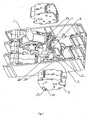
- Fig. 1 is a structural part exploded schematic view of an embodiment of a low-voltage circuit breaker of the present invention.
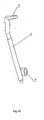
- Fig. 2 is an amplified perspective view of the rotating shaft with double wing-shape pieces, a main-body rotating shaft and activating member.
- Fig. 3a and b are a structural schematic side view and cross sectional view of the tripping device of the sensor member and the open flange.
- Fig. 4 is an inner structural schematic view of the multi-pole contact device.
- Fig. 5 is a structural schematic view of the heat energy and electromagnetic tripper.
- Fig. 6 is a perspective view of the base part with the casing.
- Fig. 7 is an amplified perspective view of the rotating shaft with a single wing-shape piece, main-body rotating shaft and activating member.
- Fig. 8 is a structural part exploded schematic view of another embodiment of the low-voltage circuit breaker of the present invention.
- Fig. 9 is an amplified perspective view of the rotating shaft with a pair of cup-shape stressed members.
- Fig. 10 is an amplified perspective view of the rotating shaft with a single cup-shape stressed member.
- the low-voltage circuit breaker has a housing with a bottom part 4, a base part 17 and a casing 18, and includes a triple-pole contact device 5 with the contacts arranged side by side; two arc-extinguishing grid chambers 14; two pairs of contact heads 12, 13 installed in the arc-extinguishing grid chamber 14, which will be separated by the electrical repulsion force generated when the current exceeds a certain value to limit the current; an operating mechanism 1 that can open and close the contact heads ; a heat energy and electromagnetic tripper 15 that can drive the operating mechanism 1 when an over-loading and/or short circuit occurs ; and a rotating shaft 8, wherein the lower end of the rotating shaft 8 is disposed on a first support member 32 of the bottom part 4, the upper end of the rotating shaft 8 is pivoted on a second support member 33 which is mechanically connected to the bottom part 4.
- the rotating shaft 8 receives the force coming from the contact device 5 by a pair of wing-shaped pieces disposed on the bottom end thereof to
- the top of the rotating shaft 8 provides an activating member 9.
- the rotating shaft 8, the activating member 9 and the wing-shaped pieces 30 are molded into an integrated structure made from plastic.
- the activating member 9 is disposed correspondingly to a latch 7.
- the open flange 6 is communicated with a chamber 34 where high-pressure gas can be produced and stored.
- the exterior surface 27 of the open flange 6 is in a cone-shape.
- a sensor member 29 is a cylinder with a taper or half ball head, jacketed in the open flange 6 and opposite to the wing-shaped pieces 30.
- Each stressed surface 20 of the wing-shaped pieces 30 is perpendicular to the axes of the open flange 6.
- the sensor member 29 floats in the open flange 6 and can move a certain distance in the axial direction.
- the sensor member 29 was confined and can only move a certain distance due to the restriction of the rotating wing-shaped pieces 30 when the sensor member 29 hits the rotating wing-shaped pieces 30.
- the sensor member 29 receives the airflow escaping from the open flange 6 of the contact device 5 and springs out to hit the rotating wing-shaped pieces 30 and produce a rotating force around the rotating shaft 8. This force is passed on to the activating member 9 and magnified, then the activating member hits the latch 7 quickly and makes a trip.
- a restoration spring 3 makes the main body of the rotating shaft 8 restore to its original position. At the same time, the sensor member 29 recovers to its original position to implement interruption when the next short circuit occurs.
- each contact device 5 provides an open flange 6 at the same side correspondingly to the wing-shaped piece 30.
- this structure is more suitable for the single-pole breaker.
- FIG. 8 and Fig. 9 Another embodiment is showed in Fig. 8 and Fig. 9 .
- the difference from the embodiment in Fig. 1 is that a stressed member 10 is disposed on the bottom of the rotating shaft and is a cup-shape.
- the exterior surface 27 of the open flange 6 of the contact device 5 is in a cylindrical shape.
- This cup-shaped stressed member 10 covers over the open flange 6. A matting distance between them is longer than the working distance of the stressed member 10.
- the contact heads 12, 13 are separated by the repulsion force to produce an electric arc and then generate energy and impact. Most of the energy and impact are consumed by the arc-extinguishing grid therein. Some of the energy and impact escape along the open flange 6 of the contact device 5.
- the cup-shaped stressed members 10 on the left and right receive the over-pressure airflow escaping from the open flanges 6 of the contact devices 5 of the two adjacent poles. A rotating force around the rotating shaft is produced, which is passed on to the activating member 9 on the top of the rotating shaft and magnified to hit the latch quickly and drive the latch to rotate around the shaft anticlockwise, then make a trip.
- the low-voltage circuit breaker can break the circuit quickly, and the breaking capability is greatly enhanced.
- the embodiment showed in Fig. 10 is an improvement based on the above embodiment. The difference is that there is a single cup-shaped stressed member 10 of the rotating shaft. In this way, each contact device 5 provides an open flange6 at the same side relative to the cup-shaped stressed member 10. This structure is more suitable for the breaker with a single pole.
Landscapes
- Physics & Mathematics (AREA)
- Electromagnetism (AREA)
- Breakers (AREA)
- Driving Mechanisms And Operating Circuits Of Arc-Extinguishing High-Tension Switches (AREA)
- Emergency Protection Circuit Devices (AREA)
- Outside Dividers And Delivering Mechanisms For Harvesters (AREA)
- Percussion Or Vibration Massage (AREA)
- Arc-Extinguishing Devices That Are Switches (AREA)
- Electronic Switches (AREA)
Claims (7)
- Niederspannungs-Unterbrecher, der die Fähigkeit aufweist, schnell auszulösen, und ein Gehäuse mit einem unteren Teil (4), einem Basisteil (17) sowie einer Verkleidung (18) aufweist und der umfasst:eine einpolige oder mehrpolige Kontakteinrichtung (5), in der eine Lichtbogenlöschgitter-Kammer (14) angeordnet ist; Kontaktköpfe (12, 13), die in der Lichtbogenlösch-Kammer installiert und so eingerichtet sind, dass sie durch die elektrisch ausgelöste Abstoßungskraft getrennt werden, die erzeugt wird, wenn ein elektrischer Strom einen bestimmten Wert übersteigt, um den Strom zu begrenzen; einen Betätigungsmechanismus (1), der die Kontaktköpfe (12, 13) trennen und schließen kann; eine mit Wärmeenergie und elektromagnetischer Kraft arbeitende Auslöseeinrichtung (15), die den Betätigungsmechanismus (1) antreiben kann, wenn eine Überlastung und/oder ein Kurzschluss auftreten/auftritt; und wobei wenigstens eine Seitenfläche (27) der Kontakteinrichtung (5) einen offenen Flansch (6) aufweist, der mit der Lichtbogenlösch-Kammer (14) verbunden ist, in der in Betrieb Hochdruckgas erzeugt und gespeichert wird, und der so eingerichtet ist, dass er auf ein Aktivierungselement (9) einwirkt, das an einer Arretierung (7) angeordnet und so eingerichtet ist, dass es eine Auslöseeinrichtung (23) des Betätigungsmechanismus (1) aktiviert, um eine Auslösung zu bewirken;dadurch gekennzeichnet, dass das Aktivierungselement (9) mit einer Drehwelle (8) verbunden ist, die an dem unteren Teil (4) angeordnet ist, wobei die Drehwelle (8) gespannte Elemente (29) aufweist, die entsprechend dem offenen Flansch (6) so angeordnet sind, dass das Hochdruckgas in Betrieb auf die gespannten Elemente (30) einwirkt, um die Drehwelle (8) zu drehen und eine Drehkraft zu erzeugen, die zu dem Aktivierungselement (9) geleitet wird, um die Arretierung (7) und die Auslöseeinrichtung (23) zu aktivieren.
- Unterbrecher nach Anspruch 1, wobei das untere Ende der Drehwelle (8) an einem ersten Trageelement (32) des unteren Teils (4) angeordnet ist und das obere Ende der Drehwelle (8) schwenkbar an einem zweiten Trageelement (33) angebracht ist und das zweite Trageelement (33) mechanisch mit dem unteren Teil (4) verbunden ist.
- Unterbrecher nach Anspruch 1 oder 2, wobei der offene Flansch der Kontakteinrichtung (5) ein schwebendes Sensorelement (29) enthält und ein Bewegungsabstand in der axialen Richtung zwischen dem Sensorelement (29) und dem offenen Flansch (6) vorhanden ist, und das gespannte Element (30) eine Flügelform hat und eine gespannte Fläche (20) senkrecht zu der Achse des offenen Flansches (6) aufweist.
- Unterbrecher nach einem der vorangehenden Ansprüche, wobei die Außenfläche (279 des offenen Flansches (6) kegelförmig ist.
- Unterbrecher nach Anspruch 3, wobei die Außenfläche (27) des offenen Flansches (6) zylinderförmig ist, das gespannte Element (30) schalenförmig ist und den offenen Flansch (6) umhüllt und ein Eingriffsabstand zwischen ihnen größer ist als die Arbeitshubstrecke des gespannten Elementes (30).
- Unterbrecher nach einem der vorangehenden Ansprüche, wobei eine Rückstellfeder (3) an der Drehwelle (8) installiert ist.
- Unterbrecher nach einem der vorangehenden Ansprüche, wobei die Drehwelle (8), das Aktivierungselement (9) und die gespannten Elemente (30) als eine integrierte Struktur ausgebildet sind.
Applications Claiming Priority (3)
| Application Number | Priority Date | Filing Date | Title |
|---|---|---|---|
| CN02136986 | 2002-09-12 | ||
| CN02136986 | 2002-09-12 | ||
| PCT/CN2003/000198 WO2004025681A1 (en) | 2002-09-12 | 2003-03-19 | Low-voltage breaker with the capability of breaking quickly |
Publications (3)
| Publication Number | Publication Date |
|---|---|
| EP1538653A1 EP1538653A1 (de) | 2005-06-08 |
| EP1538653A4 EP1538653A4 (de) | 2008-02-20 |
| EP1538653B1 true EP1538653B1 (de) | 2010-10-20 |
Family
ID=31983685
Family Applications (1)
| Application Number | Title | Priority Date | Filing Date |
|---|---|---|---|
| EP03794755A Expired - Lifetime EP1538653B1 (de) | 2002-09-12 | 2003-03-19 | Neiderspannungsunterbrecher mit der faehigkeit zum schnellen unterbrechen |
Country Status (15)
| Country | Link |
|---|---|
| US (1) | US6977567B2 (de) |
| EP (1) | EP1538653B1 (de) |
| JP (1) | JP4202321B2 (de) |
| AT (1) | ATE485594T1 (de) |
| AU (1) | AU2003236075B2 (de) |
| BR (1) | BRPI0313977B1 (de) |
| CA (1) | CA2496171C (de) |
| DE (1) | DE60334625D1 (de) |
| DK (1) | DK1538653T3 (de) |
| ES (1) | ES2359820T3 (de) |
| MA (1) | MA27471A1 (de) |
| RU (1) | RU2294575C2 (de) |
| TN (1) | TNSN05023A1 (de) |
| WO (1) | WO2004025681A1 (de) |
| ZA (1) | ZA200502896B (de) |
Families Citing this family (7)
| Publication number | Priority date | Publication date | Assignee | Title |
|---|---|---|---|---|
| ITBG20050027A1 (it) * | 2005-05-13 | 2006-11-14 | Abb Service Srl | Dispositivo di alloggiamento e connessione di accessori di interruttori. |
| US8027645B2 (en) * | 2007-12-21 | 2011-09-27 | Qualcomm Incorporated | Systems and methods for automatically tuning a frequency modulator in a mobile device |
| CN101609764B (zh) * | 2008-06-16 | 2012-07-04 | 北京人民电器厂有限公司 | 带有散热单元的触头系统 |
| DE102009015126A1 (de) * | 2009-03-31 | 2010-10-14 | Siemens Aktiengesellschaft | Auslöser für eine elektrische Schaltanordnung |
| DE102011075727A1 (de) | 2011-05-12 | 2012-11-15 | Siemens Aktiengesellschaft | Vorrichtung zum Auslösen eines elektrischen Schalters |
| DE102011077359A1 (de) * | 2011-06-10 | 2012-12-13 | Siemens Aktiengesellschaft | Auslöser für eine elektrische Schaltanordnung |
| EP3557597B1 (de) | 2018-04-20 | 2024-01-17 | ABB S.p.A. | Niederspannungsschutzschalter |
Family Cites Families (8)
| Publication number | Priority date | Publication date | Assignee | Title |
|---|---|---|---|---|
| US4430631A (en) * | 1982-05-10 | 1984-02-07 | Eaton Corporation | Circuit breaker with increased current interrupting capacity |
| US4521756A (en) * | 1983-12-08 | 1985-06-04 | Eaton Corporation | Circuit breaker having increased contact opening velocity at trip operation |
| FR2661776B1 (fr) * | 1990-05-04 | 1996-05-10 | Merlin Gerin | Declencheur instantane d'un disjoncteur. |
| FR2682530B1 (fr) * | 1991-10-15 | 1993-11-26 | Merlin Gerin | Gamme de disjoncteurs basse tension a boitier moule. |
| FR2722609B1 (fr) * | 1994-07-18 | 1996-08-30 | Schneider Electric Sa | Disjoncteur electrique a actionneur electromagnetique pour calibres eleves |
| JPH09320442A (ja) * | 1996-05-30 | 1997-12-12 | Matsushita Electric Works Ltd | 回路遮断器 |
| JP3359575B2 (ja) * | 1998-09-28 | 2002-12-24 | 寺崎電気産業株式会社 | 回路遮断器の引外し装置 |
| DE10013099B4 (de) * | 2000-03-17 | 2004-08-26 | Aeg Niederspannungstechnik Gmbh & Co Kg | Auslösevorrichtung für einen Leistungsschalter |
-
2003
- 2003-03-19 AU AU2003236075A patent/AU2003236075B2/en not_active Ceased
- 2003-03-19 DE DE60334625T patent/DE60334625D1/de not_active Expired - Lifetime
- 2003-03-19 EP EP03794755A patent/EP1538653B1/de not_active Expired - Lifetime
- 2003-03-19 WO PCT/CN2003/000198 patent/WO2004025681A1/zh not_active Ceased
- 2003-03-19 CA CA2496171A patent/CA2496171C/en not_active Expired - Lifetime
- 2003-03-19 RU RU2005110673/09A patent/RU2294575C2/ru active
- 2003-03-19 ES ES03794755T patent/ES2359820T3/es not_active Expired - Lifetime
- 2003-03-19 DK DK03794755.3T patent/DK1538653T3/da active
- 2003-03-19 AT AT03794755T patent/ATE485594T1/de not_active IP Right Cessation
- 2003-03-19 BR BRPI0313977A patent/BRPI0313977B1/pt not_active IP Right Cessation
- 2003-03-19 JP JP2004534936A patent/JP4202321B2/ja not_active Expired - Fee Related
-
2005
- 2005-01-28 TN TNP2005000023A patent/TNSN05023A1/en unknown
- 2005-03-10 US US11/075,964 patent/US6977567B2/en not_active Expired - Lifetime
- 2005-03-30 MA MA28181A patent/MA27471A1/fr unknown
- 2005-04-11 ZA ZA2005/02896A patent/ZA200502896B/en unknown
Also Published As
| Publication number | Publication date |
|---|---|
| BRPI0313977B1 (pt) | 2016-12-27 |
| BR0313977A (pt) | 2005-07-19 |
| JP4202321B2 (ja) | 2008-12-24 |
| DE60334625D1 (de) | 2010-12-02 |
| CA2496171A1 (en) | 2004-03-25 |
| ATE485594T1 (de) | 2010-11-15 |
| DK1538653T3 (da) | 2011-02-07 |
| RU2294575C2 (ru) | 2007-02-27 |
| ES2359820T3 (es) | 2011-05-27 |
| ZA200502896B (en) | 2005-12-28 |
| US6977567B2 (en) | 2005-12-20 |
| US20050151607A1 (en) | 2005-07-14 |
| CA2496171C (en) | 2010-10-12 |
| RU2005110673A (ru) | 2005-09-10 |
| AU2003236075B2 (en) | 2005-06-23 |
| JP2005538517A (ja) | 2005-12-15 |
| TNSN05023A1 (en) | 2007-05-14 |
| EP1538653A4 (de) | 2008-02-20 |
| MA27471A1 (fr) | 2005-08-01 |
| AU2003236075A1 (en) | 2004-04-30 |
| EP1538653A1 (de) | 2005-06-08 |
| WO2004025681A1 (en) | 2004-03-25 |
Similar Documents
| Publication | Publication Date | Title |
|---|---|---|
| CN107359068B (zh) | 一种具有复合灭弧性能的塑壳断路器 | |
| CN111834163B (zh) | 单极或多极断路器 | |
| CN110739166B (zh) | 配线用断路器的灭弧装置 | |
| US6590172B1 (en) | Circuit breaker mechanism for a rotary contact system | |
| EP1538653B1 (de) | Neiderspannungsunterbrecher mit der faehigkeit zum schnellen unterbrechen | |
| KR102026642B1 (ko) | 배선용 차단기 | |
| EP1863056B1 (de) | Schutzschalter | |
| KR102524505B1 (ko) | 배선용 차단기의 아크 소호 장치 | |
| CN212934526U (zh) | 一种可用于多触头断路器的触头压力控制机构 | |
| KR102522353B1 (ko) | 배선용 차단기의 아크 소호 장치 | |
| CN1245731C (zh) | 具有快速跳闸功能的低压断路器 | |
| CN213716792U (zh) | 单极或多极断路器 | |
| CN205376440U (zh) | 断路器 | |
| CN2596537Y (zh) | 具有快速跳闸功能的低压断路器 | |
| CN223052087U (zh) | 一种安全性高的断路器 | |
| CN218826931U (zh) | 一种小型断路器 | |
| CN216528713U (zh) | 一种灭弧装置及灭弧式断路器 | |
| CN220651928U (zh) | 一种万能式断路器断弧结构 | |
| CN223582930U (zh) | 一种断路器静触头组件及断路器 | |
| CN223193742U (zh) | 一种断路器的静触头灭弧模块 | |
| JP7718217B2 (ja) | 遮断器 | |
| KR20200116351A (ko) | 배선용 차단기 | |
| CN223230298U (zh) | 断路器组件 | |
| CN219350124U (zh) | 具有高分断能力的断路器结构 | |
| CN218069759U (zh) | 一种漏电保护断路器 |
Legal Events
| Date | Code | Title | Description |
|---|---|---|---|
| PUAI | Public reference made under article 153(3) epc to a published international application that has entered the european phase |
Free format text: ORIGINAL CODE: 0009012 |
|
| 17P | Request for examination filed |
Effective date: 20050315 |
|
| AK | Designated contracting states |
Kind code of ref document: A1 Designated state(s): AT BE BG CH CY CZ DE DK EE ES FI FR GB GR HU IE IT LI LU MC NL PT RO SE SI SK TR |
|
| AX | Request for extension of the european patent |
Extension state: AL LT LV MK |
|
| DAX | Request for extension of the european patent (deleted) | ||
| A4 | Supplementary search report drawn up and despatched |
Effective date: 20080118 |
|
| 17Q | First examination report despatched |
Effective date: 20090720 |
|
| GRAP | Despatch of communication of intention to grant a patent |
Free format text: ORIGINAL CODE: EPIDOSNIGR1 |
|
| GRAS | Grant fee paid |
Free format text: ORIGINAL CODE: EPIDOSNIGR3 |
|
| GRAA | (expected) grant |
Free format text: ORIGINAL CODE: 0009210 |
|
| AK | Designated contracting states |
Kind code of ref document: B1 Designated state(s): AT BE BG CH CY CZ DE DK EE ES FI FR GB GR HU IE IT LI LU MC NL PT RO SE SI SK TR |
|
| REG | Reference to a national code |
Ref country code: GB Ref legal event code: FG4D |
|
| REG | Reference to a national code |
Ref country code: CH Ref legal event code: EP |
|
| REG | Reference to a national code |
Ref country code: IE Ref legal event code: FG4D |
|
| REF | Corresponds to: |
Ref document number: 60334625 Country of ref document: DE Date of ref document: 20101202 Kind code of ref document: P |
|
| REG | Reference to a national code |
Ref country code: DK Ref legal event code: T3 |
|
| REG | Reference to a national code |
Ref country code: SE Ref legal event code: TRGR |
|
| REG | Reference to a national code |
Ref country code: NL Ref legal event code: VDEP Effective date: 20101020 |
|
| REG | Reference to a national code |
Ref country code: ES Ref legal event code: FG2A Ref document number: 2359820 Country of ref document: ES Kind code of ref document: T3 Effective date: 20110527 |
|
| PG25 | Lapsed in a contracting state [announced via postgrant information from national office to epo] |
Ref country code: BG Free format text: LAPSE BECAUSE OF FAILURE TO SUBMIT A TRANSLATION OF THE DESCRIPTION OR TO PAY THE FEE WITHIN THE PRESCRIBED TIME-LIMIT Effective date: 20110120 Ref country code: SI Free format text: LAPSE BECAUSE OF FAILURE TO SUBMIT A TRANSLATION OF THE DESCRIPTION OR TO PAY THE FEE WITHIN THE PRESCRIBED TIME-LIMIT Effective date: 20101020 Ref country code: AT Free format text: LAPSE BECAUSE OF FAILURE TO SUBMIT A TRANSLATION OF THE DESCRIPTION OR TO PAY THE FEE WITHIN THE PRESCRIBED TIME-LIMIT Effective date: 20101020 Ref country code: NL Free format text: LAPSE BECAUSE OF FAILURE TO SUBMIT A TRANSLATION OF THE DESCRIPTION OR TO PAY THE FEE WITHIN THE PRESCRIBED TIME-LIMIT Effective date: 20101020 Ref country code: PT Free format text: LAPSE BECAUSE OF FAILURE TO SUBMIT A TRANSLATION OF THE DESCRIPTION OR TO PAY THE FEE WITHIN THE PRESCRIBED TIME-LIMIT Effective date: 20110221 |
|
| PG25 | Lapsed in a contracting state [announced via postgrant information from national office to epo] |
Ref country code: BE Free format text: LAPSE BECAUSE OF FAILURE TO SUBMIT A TRANSLATION OF THE DESCRIPTION OR TO PAY THE FEE WITHIN THE PRESCRIBED TIME-LIMIT Effective date: 20101020 Ref country code: GR Free format text: LAPSE BECAUSE OF FAILURE TO SUBMIT A TRANSLATION OF THE DESCRIPTION OR TO PAY THE FEE WITHIN THE PRESCRIBED TIME-LIMIT Effective date: 20110121 |
|
| PG25 | Lapsed in a contracting state [announced via postgrant information from national office to epo] |
Ref country code: CZ Free format text: LAPSE BECAUSE OF FAILURE TO SUBMIT A TRANSLATION OF THE DESCRIPTION OR TO PAY THE FEE WITHIN THE PRESCRIBED TIME-LIMIT Effective date: 20101020 Ref country code: EE Free format text: LAPSE BECAUSE OF FAILURE TO SUBMIT A TRANSLATION OF THE DESCRIPTION OR TO PAY THE FEE WITHIN THE PRESCRIBED TIME-LIMIT Effective date: 20101020 |
|
| PLBE | No opposition filed within time limit |
Free format text: ORIGINAL CODE: 0009261 |
|
| STAA | Information on the status of an ep patent application or granted ep patent |
Free format text: STATUS: NO OPPOSITION FILED WITHIN TIME LIMIT |
|
| PG25 | Lapsed in a contracting state [announced via postgrant information from national office to epo] |
Ref country code: SK Free format text: LAPSE BECAUSE OF FAILURE TO SUBMIT A TRANSLATION OF THE DESCRIPTION OR TO PAY THE FEE WITHIN THE PRESCRIBED TIME-LIMIT Effective date: 20101020 Ref country code: RO Free format text: LAPSE BECAUSE OF FAILURE TO SUBMIT A TRANSLATION OF THE DESCRIPTION OR TO PAY THE FEE WITHIN THE PRESCRIBED TIME-LIMIT Effective date: 20101020 |
|
| 26N | No opposition filed |
Effective date: 20110721 |
|
| PG25 | Lapsed in a contracting state [announced via postgrant information from national office to epo] |
Ref country code: MC Free format text: LAPSE BECAUSE OF NON-PAYMENT OF DUE FEES Effective date: 20110331 |
|
| REG | Reference to a national code |
Ref country code: CH Ref legal event code: PL |
|
| REG | Reference to a national code |
Ref country code: DE Ref legal event code: R097 Ref document number: 60334625 Country of ref document: DE Effective date: 20110721 |
|
| REG | Reference to a national code |
Ref country code: IE Ref legal event code: MM4A |
|
| PG25 | Lapsed in a contracting state [announced via postgrant information from national office to epo] |
Ref country code: CH Free format text: LAPSE BECAUSE OF NON-PAYMENT OF DUE FEES Effective date: 20110331 Ref country code: LI Free format text: LAPSE BECAUSE OF NON-PAYMENT OF DUE FEES Effective date: 20110331 Ref country code: IE Free format text: LAPSE BECAUSE OF NON-PAYMENT OF DUE FEES Effective date: 20110319 |
|
| PG25 | Lapsed in a contracting state [announced via postgrant information from national office to epo] |
Ref country code: LU Free format text: LAPSE BECAUSE OF NON-PAYMENT OF DUE FEES Effective date: 20110319 Ref country code: CY Free format text: LAPSE BECAUSE OF FAILURE TO SUBMIT A TRANSLATION OF THE DESCRIPTION OR TO PAY THE FEE WITHIN THE PRESCRIBED TIME-LIMIT Effective date: 20101020 |
|
| PG25 | Lapsed in a contracting state [announced via postgrant information from national office to epo] |
Ref country code: TR Free format text: LAPSE BECAUSE OF FAILURE TO SUBMIT A TRANSLATION OF THE DESCRIPTION OR TO PAY THE FEE WITHIN THE PRESCRIBED TIME-LIMIT Effective date: 20101020 |
|
| PG25 | Lapsed in a contracting state [announced via postgrant information from national office to epo] |
Ref country code: HU Free format text: LAPSE BECAUSE OF FAILURE TO SUBMIT A TRANSLATION OF THE DESCRIPTION OR TO PAY THE FEE WITHIN THE PRESCRIBED TIME-LIMIT Effective date: 20101020 |
|
| REG | Reference to a national code |
Ref country code: FR Ref legal event code: PLFP Year of fee payment: 14 |
|
| REG | Reference to a national code |
Ref country code: FR Ref legal event code: PLFP Year of fee payment: 15 |
|
| REG | Reference to a national code |
Ref country code: FR Ref legal event code: PLFP Year of fee payment: 16 |
|
| PGFP | Annual fee paid to national office [announced via postgrant information from national office to epo] |
Ref country code: GB Payment date: 20220331 Year of fee payment: 20 Ref country code: FI Payment date: 20220331 Year of fee payment: 20 Ref country code: DK Payment date: 20220331 Year of fee payment: 20 |
|
| PGFP | Annual fee paid to national office [announced via postgrant information from national office to epo] |
Ref country code: SE Payment date: 20220331 Year of fee payment: 20 Ref country code: FR Payment date: 20220330 Year of fee payment: 20 |
|
| PGFP | Annual fee paid to national office [announced via postgrant information from national office to epo] |
Ref country code: IT Payment date: 20220331 Year of fee payment: 20 Ref country code: ES Payment date: 20220407 Year of fee payment: 20 Ref country code: DE Payment date: 20220513 Year of fee payment: 20 |
|
| REG | Reference to a national code |
Ref country code: DE Ref legal event code: R071 Ref document number: 60334625 Country of ref document: DE |
|
| REG | Reference to a national code |
Ref country code: DK Ref legal event code: EUP Expiry date: 20230319 |
|
| REG | Reference to a national code |
Ref country code: GB Ref legal event code: PE20 Expiry date: 20230318 |
|
| REG | Reference to a national code |
Ref country code: ES Ref legal event code: FD2A Effective date: 20230426 |
|
| REG | Reference to a national code |
Ref country code: SE Ref legal event code: EUG |
|
| PG25 | Lapsed in a contracting state [announced via postgrant information from national office to epo] |
Ref country code: GB Free format text: LAPSE BECAUSE OF EXPIRATION OF PROTECTION Effective date: 20230318 |
|
| PG25 | Lapsed in a contracting state [announced via postgrant information from national office to epo] |
Ref country code: ES Free format text: LAPSE BECAUSE OF EXPIRATION OF PROTECTION Effective date: 20230320 |