EP1538485A1 - Verfahren zur Vorbereitung eines Substrats, Messverfahren, Verfahren zur Herstellung einer Vorrichtung, Lithographischer Apparat, Computerprogramm und Substrat - Google Patents
Verfahren zur Vorbereitung eines Substrats, Messverfahren, Verfahren zur Herstellung einer Vorrichtung, Lithographischer Apparat, Computerprogramm und Substrat Download PDFInfo
- Publication number
- EP1538485A1 EP1538485A1 EP04257363A EP04257363A EP1538485A1 EP 1538485 A1 EP1538485 A1 EP 1538485A1 EP 04257363 A EP04257363 A EP 04257363A EP 04257363 A EP04257363 A EP 04257363A EP 1538485 A1 EP1538485 A1 EP 1538485A1
- Authority
- EP
- European Patent Office
- Prior art keywords
- substrate
- alignment markers
- orientation
- crystal axis
- markers
- Prior art date
- Legal status (The legal status is an assumption and is not a legal conclusion. Google has not performed a legal analysis and makes no representation as to the accuracy of the status listed.)
- Granted
Links
Images

Classifications
-
- G—PHYSICS
- G03—PHOTOGRAPHY; CINEMATOGRAPHY; ANALOGOUS TECHNIQUES USING WAVES OTHER THAN OPTICAL WAVES; ELECTROGRAPHY; HOLOGRAPHY
- G03F—PHOTOMECHANICAL PRODUCTION OF TEXTURED OR PATTERNED SURFACES, e.g. FOR PRINTING, FOR PROCESSING OF SEMICONDUCTOR DEVICES; MATERIALS THEREFOR; ORIGINALS THEREFOR; APPARATUS SPECIALLY ADAPTED THEREFOR
- G03F9/00—Registration or positioning of originals, masks, frames, photographic sheets or textured or patterned surfaces, e.g. automatically
- G03F9/70—Registration or positioning of originals, masks, frames, photographic sheets or textured or patterned surfaces, e.g. automatically for microlithography
- G03F9/7073—Alignment marks and their environment
- G03F9/7084—Position of mark on substrate, i.e. position in (x, y, z) of mark, e.g. buried or resist covered mark, mark on rearside, at the substrate edge, in the circuit area, latent image mark, marks in plural levels
-
- G—PHYSICS
- G03—PHOTOGRAPHY; CINEMATOGRAPHY; ANALOGOUS TECHNIQUES USING WAVES OTHER THAN OPTICAL WAVES; ELECTROGRAPHY; HOLOGRAPHY
- G03F—PHOTOMECHANICAL PRODUCTION OF TEXTURED OR PATTERNED SURFACES, e.g. FOR PRINTING, FOR PROCESSING OF SEMICONDUCTOR DEVICES; MATERIALS THEREFOR; ORIGINALS THEREFOR; APPARATUS SPECIALLY ADAPTED THEREFOR
- G03F9/00—Registration or positioning of originals, masks, frames, photographic sheets or textured or patterned surfaces, e.g. automatically
- G03F9/70—Registration or positioning of originals, masks, frames, photographic sheets or textured or patterned surfaces, e.g. automatically for microlithography
- G03F9/7003—Alignment type or strategy, e.g. leveling, global alignment
-
- G—PHYSICS
- G03—PHOTOGRAPHY; CINEMATOGRAPHY; ANALOGOUS TECHNIQUES USING WAVES OTHER THAN OPTICAL WAVES; ELECTROGRAPHY; HOLOGRAPHY
- G03F—PHOTOMECHANICAL PRODUCTION OF TEXTURED OR PATTERNED SURFACES, e.g. FOR PRINTING, FOR PROCESSING OF SEMICONDUCTOR DEVICES; MATERIALS THEREFOR; ORIGINALS THEREFOR; APPARATUS SPECIALLY ADAPTED THEREFOR
- G03F9/00—Registration or positioning of originals, masks, frames, photographic sheets or textured or patterned surfaces, e.g. automatically
- G03F9/70—Registration or positioning of originals, masks, frames, photographic sheets or textured or patterned surfaces, e.g. automatically for microlithography
- G03F9/7073—Alignment marks and their environment
- G03F9/7076—Mark details, e.g. phase grating mark, temporary mark
-
- Y—GENERAL TAGGING OF NEW TECHNOLOGICAL DEVELOPMENTS; GENERAL TAGGING OF CROSS-SECTIONAL TECHNOLOGIES SPANNING OVER SEVERAL SECTIONS OF THE IPC; TECHNICAL SUBJECTS COVERED BY FORMER USPC CROSS-REFERENCE ART COLLECTIONS [XRACs] AND DIGESTS
- Y10—TECHNICAL SUBJECTS COVERED BY FORMER USPC
- Y10S—TECHNICAL SUBJECTS COVERED BY FORMER USPC CROSS-REFERENCE ART COLLECTIONS [XRACs] AND DIGESTS
- Y10S438/00—Semiconductor device manufacturing: process
- Y10S438/975—Substrate or mask aligning feature
Definitions
- the present invention relates to a method of preparing a substrate, a method of measuring, a device manufacturing method, a lithographic apparatus, a computer program for controlling the lithographic apparatus and a substrate.
- a lithographic apparatus is a machine that applies a desired pattern onto a target portion of a substrate.
- Lithographic apparatus can be used, for example, in the manufacture of integrated circuits (ICs).
- a patterning means such as a mask, may be used to generate a circuit pattern corresponding to an individual layer of the IC, and this pattern can be imaged onto a target portion (e.g. comprising part of, one or several dies) on a substrate (e.g. a silicon wafer) that has a layer of radiation-sensitive material (resist).
- a single substrate will contain a network of adjacent target portions that are successively exposed.
- lithographic apparatus include so-called steppers, in which each target portion is irradiated by exposing an entire pattern onto the target portion in one go, and so-called scanners, in which each target portion is irradiated by scanning the pattern through the projection beam in a given direction (the "scanning"-direction) while synchronously scanning the substrate parallel or anti-parallel to this direction.
- Some devices that are made by lithographic techniques need to be correctly aligned to the crystal structure of the substrate on which they are built.
- the flat is formed by cleaving the silicon crystal before it is sawn into wafers and hence gives an indication of the crystal axis.
- the position of the notch indicates the orientation of the crystal axis.
- both flats and notches only indicate the ⁇ 110 ⁇ crystal axis to within ⁇ 1° which is insufficient for many applications.
- GaAs ⁇ 011 ⁇ and InP ⁇ 011 ⁇ wafers are typically specified with a tolerance of ⁇ 0.5° but again more accurate alignment is often necessary.
- a method of preparing a substrate comprising:
- the alignment system built into a lithographic apparatus may be used.
- the orientations of the alignment markers preferably span the expected range of variation of the orientation of the crystal axis and a little way either side, for example between 0.5° to 2° either side of a nominal orientation of said crystal axis.
- the orientations of said alignment markers may differ from each other by amounts in the range of from (5x10 -6 )° to 4°.
- the smallest increment of angle may be determined by the minimum rotational step of the substrate table of a lithographic apparatus used to print and/or measure the markers.
- the dependence on orientation of the markers' positions is provided by etching said alignment markers into said substrate using an anisotropic etching process.
- a method of determining the orientation of the crystal structure of a substrate the substrate having provided thereon a plurality of alignment markers at respective predetermined positions, different ones of said alignment markers having different orientations relative to a crystal axis of said substrate; the method comprising:
- This method may be used with the substrates of the first aspect of the invention to obtain the desired measurement of the orientation of the crystal axis.
- the measurement of the orientation of the crystal axis may be carried out at a different time, and possibly also place, in which case it is desirable to mark on said substrate and/or other substrates cut from the same crystal, information indicative of the determined orientation. or to make an entry in a database representing said determined orientation.
- Yet a further aspect of the present invention provides a device manufacturing method comprising the steps of:
- the markers from which the orientation of the crystal axis is derived may be provided on the opposite side of the substrate than the devices that are to be manufactured. Also, the information indicative of the orientation of a crystal axis can be derived from measurements of a different substrate cut from the same single crystal.
- the alignment marker may take the form of any standard markers, for example gratings, groups of gratings, chevrons, boxes. Sensitivity to orientation can be provided by including in each marker at least one area having a plurality of small elements on a contrasting background.
- the invention provides a lithographic apparatus arranged to perform the above described methods and computer program to instruct a lithographic apparatus to perform the methods of the invention.
- lithographic apparatus in the manufacture of ICs, it should be understood that the lithographic apparatus described herein may have other applications, such as the manufacture of integrated optical systems, guidance and detection patterns for magnetic domain memories, liquid-crystal displays (LCDs), thin-film magnetic heads, etc.
- LCDs liquid-crystal displays
- any use of the terms “wafer” or “die” herein may be considered as synonymous with the more general terms “substrate” or "target portion”, respectively.
- the substrate referred to herein may be processed, before or after exposure, in for example a track (a tool that typically applies a layer of resist to a substrate and develops the exposed resist) or a metrology or inspection tool.
- the disclosure herein may be applied to such and other substrate processing tools.
- the substrate may be processed more than once, for example in order to create a multi-layer IC, so that the term substrate used herein may also refer to a substrate that already contains multiple processed layers.
- UV radiation e.g. having a wavelength of 365, 248, 193, 157 or 126 nm
- EUV extreme ultra-violet
- particle beams such as ion beams or electron beams.
- patterning means used herein should be broadly interpreted as referring to means that can be used to impart a projection beam with a pattern in its cross-section such as to create a pattern in a target portion of the substrate. It should be noted that the pattern imparted to the projection beam may not exactly correspond to the desired pattern in the target portion of the substrate. Generally, the pattern imparted to the projection beam will correspond to a particular functional layer in a device being created in the target portion, such as an integrated circuit.
- Patterning means may be transmissive or reflective.
- Examples of patterning means include masks, programmable mirror arrays, and programmable LCD panels.
- Masks are well known in lithography, and include mask types such as binary, alternating phase-shift, and attenuated phase-shift, as well as various hybrid mask types.
- An example of a programmable mirror array employs a matrix arrangement of small mirrors, each of which can be individually tilted so as to reflect an incoming radiation beam in different directions; in this manner, the reflected beam is patterned.
- the support structure may be a frame or table, for example, which may be fixed or movable as required and which may ensure that the patterning means is at a desired position, for example with respect to the projection system. Any use of the terms "reticle” or “mask” herein may be considered synonymous with the more general term "patterning means”.
- projection system used herein should be broadly interpreted as encompassing various types of projection system, including refractive optical systems, reflective optical systems, and catadioptric optical systems, as appropriate for example for the exposure radiation being used, or for other factors such as the use of an immersion fluid or the use of a vacuum. Any use of the term “lens” herein may be considered as synonymous with the more general term “projection system”.
- the illumination system may also encompass various types of optical components, including refractive, reflective, and catadioptric optical components for directing, shaping, or controlling the projection beam of radiation, and such components may also be referred to below, collectively or singularly, as a "lens”.
- the lithographic apparatus may be of a type having two (dual stage) or more substrate tables (and/or two or more mask tables). In such "multiple stage” machines the additional tables may be used in parallel, or preparatory steps may be carried out on one or more tables while one or more other tables are being used for exposure.
- the lithographic apparatus may also be of a type wherein the substrate is immersed in a liquid having a relatively high refractive index, e.g. water, so as to fill a space between the final element of the projection system and the substrate.
- Immersion liquids may also be applied to other spaces in the lithographic apparatus, for example, between the mask and the first element of the projection system. Immersion techniques are well known in the art for increasing the numerical aperture of projection systems.
- Figure 1 schematically depicts a lithographic apparatus according to a particular embodiment of the invention.
- the apparatus comprises:
- the apparatus is of a transmissive type (e.g. employing a transmissive mask).
- the apparatus may be of a reflective type (e.g. employing a programmable mirror array of a type as referred to above).
- the illuminator IL receives a beam of radiation from a radiation source SO.
- the source and the lithographic apparatus may be separate entities, for example when the source is an excimer laser. In such cases, the source is not considered to form part of the lithographic apparatus and the radiation beam is passed from the source SO to the illuminator IL with the aid of a beam delivery system BD comprising for example suitable directing mirrors and/or a beam expander. In other cases the source may be integral part of the apparatus, for example when the source is a mercury lamp.
- the source SO and the illuminator IL, together with the beam delivery system BD if required, may be referred to as a radiation system.
- the illuminator IL may comprise adjusting means AM for adjusting the angular intensity distribution of the beam.
- adjusting means AM for adjusting the angular intensity distribution of the beam.
- the illuminator IL generally comprises various other components, such as an integrator IN and a condenser CO.
- the illuminator provides a conditioned beam of radiation, referred to as the projection beam PB, having a desired uniformity and intensity distribution in its cross-section.
- the projection beam PB is incident on the mask MA, which is held on the mask table MT. Having traversed the mask MA, the projection beam PB passes through the lens PL, which focuses the beam onto a target portion C of the substrate W.
- the substrate table WT can be moved accurately, e.g. so as to position different target portions C in the path of the beam PB.
- the first positioning means PM and another position sensor can be used to accurately position the mask MA with respect to the path of the beam PB, e.g. after mechanical retrieval from a mask library, or during a scan.
- the mask table MT may be connected to a short stroke actuator only, or may be fixed.
- Mask MA and substrate W may be aligned using mask alignment marks M1, M2 and substrate alignment marks P1, P2.
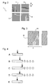
- FIG 2 shows an alignment marker 1 which is based on a standard form of marker but modified for use in the invention.
- the alignment marker 1 comprises four quadrants 11 to 14 each of which comprises a grating structure. Two of the quadrants 11, 14 have their grating lines aligned in a first direction, horizontal in the Figure, and the other two quadrants 12, 13 have their grating lines arranged in the perpendicular direction, vertical in the Figure.
- the grating lines in quadrants 11 and 14 are modified from the standard form to enable measurement of the orientation of the crystal axis.
- the grating period p comprises a structure of three parts: a solid area 2, a clear area 3 and a striped area 4.
- the striped area has a number of lines, four in the present embodiment but more or fewer may also be used, with a line width and pitch much smaller than the pitch of the grating 14, which may be about 16 ⁇ m.
- the critical dimensions of the features of the orientation-sensitive part of the marker are preferably as small as can be printed with the lithographic apparatus used to print the marker. This marker can be made sensitive to its orientation relative to the crystal axis of the substrate by etching it into the substrate using an anisotropic etching step.
- the substrate is preferentially etched in a particular direction, e.g. parallel to the ⁇ 001 ⁇ crystal axis, as compared to the perpendicular direction. If the marker is aligned to the direction of preferential etching, the orientation-sensitive (striped) parts of the marker will etch more strongly than if the marker is at an angle to that direction so that the center of gravity of the marker will shift. How this effect is achieved is shown in Figures 4A to E.
- Figures 4A to E show in cross-section the structures resulting when the marker is exposed in resist at various different angles relative to the crystal axis and then etched into the substrate with an anisotropic etch process.
- the details of the anisotropic etch procedure will determine the precise angles under which the structures are etched and the exact forms of the structures etched at different angles.
- the marker is at a large positive angle to the crystal axis, the lines of the stripped area are completely etched away and the marker consists only of the solid parts.
- the result is a positioned centered on the solid areas, as shown by the arrow.
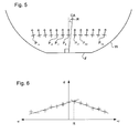
- Figure 5 shows a wafer W on which the method of the present invention is used to find the orientation of the crystal axis CA.
- the wafer W has a flat F which is nominally perpendicular to the crystal axis CA but in practice the crystal axis CA may be at an angle R of up to ⁇ 1° away from the normal to the flat. (NB certain angles and the sizes of the markers in Figure 5 are exaggerated for clarity.)
- a series of alignment markers P -n to P +n is exposed into resist on the substrate at differing angles r n relative to the normal to the flat F.
- the angles of the markers P -n to P +n should span, and preferably go beyond, the range of possible angles of the crystal axis C and should be sufficient in number to provide a sufficient number of data points for interpolation and to average errors.
- the markers are preferably exposed under the same conditions (or else relevant variations are factored out later in the method) and preferably conditions optimum for the correct imaging of the striped part of the marker.
- the markers may be exposed in a single exposure, with a suitable mask containing images of all the markers at the respective angles, or in separate exposures, using a mask with an image of a single marker with the substrate rotated appropriately for each imaging step.
- the markers are preferably printed close together to minimize any position dependent effects in imaging and may be printed in any spare space on the substrate if it is to be used for production of devices. There is no need for the markers to be positioned with a specific or consistent relationship between their position and their orientation relative to the normal to the flat F but their relative positions must be known to an appropriate degree of accuracy. If the global position markers have already been printed on the substrate, or are printed at the same time, the predetermined positions of the markers for crystal axis determination are preferably known relative to the global position markers.
- the resist is then developed in the usual way and the alignment markers P -n to P +n are etched into the substrate with an anisotropic etching process.
- the exact etching process will depend on the material of the substrate, suitable processes are known for common substrate materials.
- a suitable anisotropic etching process for a silicon substrate is a KOH etch for which the process conditions, especially the temperature, can be optimized to maximize the directional selectivity of the etch.
- the absolute positions of the etched markers P -n to P +n are measured using a standard alignment tool, e.g. the alignment tool built into a lithographic projection apparatus, and their displacements d from their expected positions are determined.
- the alignment scans may'be carried out with the substrate table appropriately rotated so that the scans are correctly perpendicular to the markers.
- the closer the orientation of the alignment marker is to the crystal axis CA the more strongly the striped part will have etched and so the more its center of gravity will have shifted, leading to a greater displacement of measured position from the nominal position at which it was exposed.
- the marker with the greatest apparent displacement can therefore be used as an indication of the orientation of the crystal axis.
- the displacements of all markers can be considered.
- the displacements d may be fitted to two straight lines, one rising and one falling with increasing angle relative to the normal to the flat, and the orientation of the crystal axis is then determined from the intersection of the two lines, as shown in Figure 6.
- the orientation of the crystal axis relative to the flat may be taken into account in the production of devices on the substrate.
- a device whose function is dependent on, or improved by, an exact alignment with one or other crystal axis if the orientation of one crystal axis is known it is of course a matter of simple geometry to determine the orientation of the others) can be correctly positioned on the device. Correct positioning may be achieved by using known crystal axis orientation to appropriately position the global positioning (zero level) markers on the substrate or, if the positions of these are already fixed, the crystal axis orientation can be carried forward as a correction factor applied after alignment to the global positioning markers.
- the steps of the present invention need not all be carried out at the same time or place.
- the series of markers may be exposed and etched at the time and place of manufacture of the substrate whereas the measurement of the apparent displacements and the determination of the value of the offset may be carried out when devices are to be exposed on the substrate.
- This as with the case when all steps are carried out at the time of production of devices, has the advantage that the existing, highly accurate alignment systems of a lithographic apparatus may be used for the measurements.
- the substrate is not removed from a substrate table between measurement of the crystal axis offset and printing of the global positioning markers, then the possibility of error in using the flat as a reference is avoided.
- the measurement of the invention can be carried out on one (or perhaps a sample to minimize error) substrate cut from a given crystal and the result then applied to all substrates cut from that crystal.
- the measurement result may be marked on the substrate or an associated data carrier, in machine or human readable form, or entered into a database for retrieval at the time of use of the substrate.
- the markers used in the method of the present invention may take up an undesirable amount of space on the substrate, they may be put on the opposite side of the substrate to that used for production of devices, remembering of course that the offset value will need to have its sign changed when applied after inversion of the wafer. It may also be possible in some circumstances to remove the markers after they have been used in the method of the invention.
- the invention can be implemented in the form of a software upgrade to an existing apparatus and hence may be provided in the form of a computer program that includes code that is executed by the supervisory control system of the lithographic apparatus and instructs the lithographic apparatus to perform the steps of the method of the invention.
Landscapes
- Physics & Mathematics (AREA)
- General Physics & Mathematics (AREA)
- Exposure And Positioning Against Photoresist Photosensitive Materials (AREA)
- Container, Conveyance, Adherence, Positioning, Of Wafer (AREA)
- Exposure Of Semiconductors, Excluding Electron Or Ion Beam Exposure (AREA)
Applications Claiming Priority (2)
| Application Number | Priority Date | Filing Date | Title |
|---|---|---|---|
| US10/724,403 US7253077B2 (en) | 2003-12-01 | 2003-12-01 | Substrate, method of preparing a substrate, method of measurement, lithographic apparatus, device manufacturing method and device manufactured thereby, and machine-readable storage medium |
| US724403 | 2003-12-01 |
Publications (2)
| Publication Number | Publication Date |
|---|---|
| EP1538485A1 true EP1538485A1 (de) | 2005-06-08 |
| EP1538485B1 EP1538485B1 (de) | 2008-07-30 |
Family
ID=34465726
Family Applications (1)
| Application Number | Title | Priority Date | Filing Date |
|---|---|---|---|
| EP04257363A Expired - Lifetime EP1538485B1 (de) | 2003-12-01 | 2004-11-26 | Verfahren zur Vorbereitung eines Substrats, Messverfahren, Verfahren zur Herstellung einer Vorrichtung, Lithographischer Apparat, Computerprogramm und Substrat |
Country Status (8)
| Country | Link |
|---|---|
| US (1) | US7253077B2 (de) |
| EP (1) | EP1538485B1 (de) |
| JP (1) | JP4157518B2 (de) |
| KR (1) | KR100700370B1 (de) |
| CN (1) | CN1624589A (de) |
| DE (1) | DE602004015397D1 (de) |
| SG (1) | SG112071A1 (de) |
| TW (1) | TWI282912B (de) |
Cited By (1)
| Publication number | Priority date | Publication date | Assignee | Title |
|---|---|---|---|---|
| WO2018077587A1 (en) * | 2016-10-24 | 2018-05-03 | Asml Netherlands B.V. | Lithographic apparatus and method |
Families Citing this family (8)
| Publication number | Priority date | Publication date | Assignee | Title |
|---|---|---|---|---|
| JP4560479B2 (ja) * | 2005-12-06 | 2010-10-13 | Okiセミコンダクタ株式会社 | 多モード光干渉デバイスの製造方法 |
| WO2008092936A2 (en) * | 2007-02-02 | 2008-08-07 | Lexas Research Ltd. | Method and apparatus for measuring process parameters of a plasma etch process |
| US8389099B1 (en) | 2007-06-01 | 2013-03-05 | Rubicon Technology, Inc. | Asymmetrical wafer configurations and method for creating the same |
| US20140300695A1 (en) * | 2007-08-11 | 2014-10-09 | Massachusetts Institute Of Technology | Full-Parallax Acousto-Optic/Electro-Optic Holographic Video Display |
| CN105428292B (zh) * | 2015-11-17 | 2018-08-03 | 中国科学技术大学 | 一种光栅掩模与硅片{111}晶面的对准方法 |
| KR102634804B1 (ko) | 2018-11-06 | 2024-02-08 | 에이에스엠엘 네델란즈 비.브이. | 하전 입자 빔 장치에서 웨이퍼를 열적으로 컨디셔닝하는 시스템들 및 방법들 |
| CN113675074B (zh) * | 2020-05-15 | 2023-09-29 | 中芯国际集成电路制造(上海)有限公司 | 半导体版图及其形成方法、形成的半导体结构及方法 |
| US20230197842A1 (en) * | 2021-12-20 | 2023-06-22 | International Business Machines Corporation | High electron mobility transistor with gate electrode below the channel |
Citations (3)
| Publication number | Priority date | Publication date | Assignee | Title |
|---|---|---|---|---|
| US6177285B1 (en) * | 1996-03-01 | 2001-01-23 | Siemens Aktiengesellschaft | Process for determining the crystal orientation in a wafer |
| US20010020750A1 (en) * | 2000-03-07 | 2001-09-13 | Teiichirou Chiba | Semiconductor wafer and method of specifying crystallographic axis orientation thereof |
| US20020072193A1 (en) * | 2000-12-08 | 2002-06-13 | Robert Antaki | Method of aligning a photolithographic mask to a crystal plane |
Family Cites Families (8)
| Publication number | Priority date | Publication date | Assignee | Title |
|---|---|---|---|---|
| US5523193A (en) * | 1988-05-31 | 1996-06-04 | Texas Instruments Incorporated | Method and apparatus for patterning and imaging member |
| US5296891A (en) * | 1990-05-02 | 1994-03-22 | Fraunhofer-Gesellschaft Zur Forderung Der Angewandten Forschung E.V. | Illumination device |
| US5229872A (en) * | 1992-01-21 | 1993-07-20 | Hughes Aircraft Company | Exposure device including an electrically aligned electronic mask for micropatterning |
| EP0824722B1 (de) * | 1996-03-06 | 2001-07-25 | Asm Lithography B.V. | Differential-interferometer-system und lithographischer "step and scan" apparat ausgestattet mit diesem system |
| WO1998028665A1 (en) * | 1996-12-24 | 1998-07-02 | Koninklijke Philips Electronics N.V. | Two-dimensionally balanced positioning device with two object holders, and lithographic device provided with such a positioning device |
| DE69711929T2 (de) | 1997-01-29 | 2002-09-05 | Micronic Laser Systems Ab, Taeby | Verfahren und gerät zur erzeugung eines musters auf einem mit fotoresist beschichteten substrat mittels fokusiertem laserstrahl |
| SE509062C2 (sv) | 1997-02-28 | 1998-11-30 | Micronic Laser Systems Ab | Dataomvandlingsmetod för en laserskrivare med flera strålar för mycket komplexa mikrokolitografiska mönster |
| EP0900412B1 (de) | 1997-03-10 | 2005-04-06 | ASML Netherlands B.V. | Lithographiegerät mit einer positioniervorrichtung mit zwei objekthaltern |
-
2003
- 2003-12-01 US US10/724,403 patent/US7253077B2/en not_active Expired - Fee Related
-
2004
- 2004-11-18 TW TW093135462A patent/TWI282912B/zh not_active IP Right Cessation
- 2004-11-26 EP EP04257363A patent/EP1538485B1/de not_active Expired - Lifetime
- 2004-11-26 DE DE602004015397T patent/DE602004015397D1/de not_active Expired - Lifetime
- 2004-11-30 SG SG200406966A patent/SG112071A1/en unknown
- 2004-11-30 KR KR1020040099076A patent/KR100700370B1/ko not_active Expired - Fee Related
- 2004-11-30 JP JP2004346399A patent/JP4157518B2/ja not_active Expired - Fee Related
- 2004-11-30 CN CNA2004101000274A patent/CN1624589A/zh active Pending
Patent Citations (3)
| Publication number | Priority date | Publication date | Assignee | Title |
|---|---|---|---|---|
| US6177285B1 (en) * | 1996-03-01 | 2001-01-23 | Siemens Aktiengesellschaft | Process for determining the crystal orientation in a wafer |
| US20010020750A1 (en) * | 2000-03-07 | 2001-09-13 | Teiichirou Chiba | Semiconductor wafer and method of specifying crystallographic axis orientation thereof |
| US20020072193A1 (en) * | 2000-12-08 | 2002-06-13 | Robert Antaki | Method of aligning a photolithographic mask to a crystal plane |
Non-Patent Citations (1)
| Title |
|---|
| LAI J M ET AL: "PRECISION ALIGNMENT OF MASK ETCHING WITH RESPECT TO CRYSTAL ORIENTATION", JOURNAL OF MICROMECHANICS & MICROENGINEERING, NEW YORK, NY, US, vol. 8, no. 4, December 1998 (1998-12-01), pages 327 - 329, XP001028556, ISSN: 0960-1317 * |
Cited By (1)
| Publication number | Priority date | Publication date | Assignee | Title |
|---|---|---|---|---|
| WO2018077587A1 (en) * | 2016-10-24 | 2018-05-03 | Asml Netherlands B.V. | Lithographic apparatus and method |
Also Published As
| Publication number | Publication date |
|---|---|
| JP4157518B2 (ja) | 2008-10-01 |
| TWI282912B (en) | 2007-06-21 |
| DE602004015397D1 (de) | 2008-09-11 |
| EP1538485B1 (de) | 2008-07-30 |
| KR100700370B1 (ko) | 2007-03-27 |
| CN1624589A (zh) | 2005-06-08 |
| US7253077B2 (en) | 2007-08-07 |
| KR20050053012A (ko) | 2005-06-07 |
| JP2005167247A (ja) | 2005-06-23 |
| US20050118781A1 (en) | 2005-06-02 |
| SG112071A1 (en) | 2005-06-29 |
| TW200527157A (en) | 2005-08-16 |
Similar Documents
| Publication | Publication Date | Title |
|---|---|---|
| US8289516B2 (en) | Method of measuring focus of a lithographic projection apparatus | |
| US8064056B2 (en) | Substrate used in a method and apparatus for angular-resolved spectroscopic lithography characterization | |
| US20080030701A1 (en) | Individual wafer history storage for overlay corrections | |
| US7992115B2 (en) | Overlay measurement on double patterning substrate | |
| US8252491B2 (en) | Method of forming a marker, substrate having a marker and device manufacturing method | |
| EP1538485B1 (de) | Verfahren zur Vorbereitung eines Substrats, Messverfahren, Verfahren zur Herstellung einer Vorrichtung, Lithographischer Apparat, Computerprogramm und Substrat | |
| KR100825453B1 (ko) | 투영시스템의 배율측정방법, 디바이스 제조방법 및 컴퓨터프로그램물 | |
| US7453063B2 (en) | Calibration substrate and method for calibrating a lithographic apparatus | |
| EP1739491B1 (de) | Fokusbestimmungsverfahren und Verfahren zur Herstellung einer Vorrichtung | |
| US7102736B2 (en) | Method of calibration, calibration substrate, and method of device manufacture | |
| US20060035159A1 (en) | Method of providing alignment marks, method of aligning a substrate, device manufacturing method, computer program, and device | |
| US7518706B2 (en) | Exposure apparatus, a tilting device method for performing a tilted focus test, and a device manufactured accordingly | |
| US7894063B2 (en) | Lithographic method | |
| EP1760525A1 (de) | Verfahren zur Herstellung einer Vorrichtung, Maske und Vorrichtung |
Legal Events
| Date | Code | Title | Description |
|---|---|---|---|
| PUAI | Public reference made under article 153(3) epc to a published international application that has entered the european phase |
Free format text: ORIGINAL CODE: 0009012 |
|
| AK | Designated contracting states |
Kind code of ref document: A1 Designated state(s): AT BE BG CH CY CZ DE DK EE ES FI FR GB GR HU IE IS IT LI LU MC NL PL PT RO SE SI SK TR |
|
| AX | Request for extension of the european patent |
Extension state: AL HR LT LV MK YU |
|
| 17P | Request for examination filed |
Effective date: 20051021 |
|
| AKX | Designation fees paid |
Designated state(s): DE FR GB IT NL |
|
| GRAP | Despatch of communication of intention to grant a patent |
Free format text: ORIGINAL CODE: EPIDOSNIGR1 |
|
| GRAS | Grant fee paid |
Free format text: ORIGINAL CODE: EPIDOSNIGR3 |
|
| GRAA | (expected) grant |
Free format text: ORIGINAL CODE: 0009210 |
|
| AK | Designated contracting states |
Kind code of ref document: B1 Designated state(s): DE FR GB IT NL |
|
| REG | Reference to a national code |
Ref country code: GB Ref legal event code: FG4D |
|
| REF | Corresponds to: |
Ref document number: 602004015397 Country of ref document: DE Date of ref document: 20080911 Kind code of ref document: P |
|
| PLBE | No opposition filed within time limit |
Free format text: ORIGINAL CODE: 0009261 |
|
| STAA | Information on the status of an ep patent application or granted ep patent |
Free format text: STATUS: NO OPPOSITION FILED WITHIN TIME LIMIT |
|
| 26N | No opposition filed |
Effective date: 20090506 |
|
| PGFP | Annual fee paid to national office [announced via postgrant information from national office to epo] |
Ref country code: NL Payment date: 20091112 Year of fee payment: 6 |
|
| PGFP | Annual fee paid to national office [announced via postgrant information from national office to epo] |
Ref country code: GB Payment date: 20091119 Year of fee payment: 6 Ref country code: IT Payment date: 20091124 Year of fee payment: 6 |
|
| REG | Reference to a national code |
Ref country code: NL Ref legal event code: V1 Effective date: 20110601 |
|
| GBPC | Gb: european patent ceased through non-payment of renewal fee |
Effective date: 20101126 |
|
| PG25 | Lapsed in a contracting state [announced via postgrant information from national office to epo] |
Ref country code: NL Free format text: LAPSE BECAUSE OF NON-PAYMENT OF DUE FEES Effective date: 20110601 |
|
| PG25 | Lapsed in a contracting state [announced via postgrant information from national office to epo] |
Ref country code: GB Free format text: LAPSE BECAUSE OF NON-PAYMENT OF DUE FEES Effective date: 20101126 |
|
| PG25 | Lapsed in a contracting state [announced via postgrant information from national office to epo] |
Ref country code: IT Free format text: LAPSE BECAUSE OF NON-PAYMENT OF DUE FEES Effective date: 20101126 |
|
| REG | Reference to a national code |
Ref country code: FR Ref legal event code: PLFP Year of fee payment: 12 |
|
| REG | Reference to a national code |
Ref country code: FR Ref legal event code: PLFP Year of fee payment: 13 |
|
| REG | Reference to a national code |
Ref country code: FR Ref legal event code: PLFP Year of fee payment: 14 |
|
| PGFP | Annual fee paid to national office [announced via postgrant information from national office to epo] |
Ref country code: DE Payment date: 20181120 Year of fee payment: 15 |
|
| PGFP | Annual fee paid to national office [announced via postgrant information from national office to epo] |
Ref country code: FR Payment date: 20181123 Year of fee payment: 15 |
|
| REG | Reference to a national code |
Ref country code: DE Ref legal event code: R119 Ref document number: 602004015397 Country of ref document: DE |
|
| PG25 | Lapsed in a contracting state [announced via postgrant information from national office to epo] |
Ref country code: DE Free format text: LAPSE BECAUSE OF NON-PAYMENT OF DUE FEES Effective date: 20200603 Ref country code: FR Free format text: LAPSE BECAUSE OF NON-PAYMENT OF DUE FEES Effective date: 20191130 |