EP1538416B1 - Verfahren und Vorrichtung zum Wiederaufbau von Bildern auf Detektorstäben - Google Patents
Verfahren und Vorrichtung zum Wiederaufbau von Bildern auf Detektorstäben Download PDFInfo
- Publication number
- EP1538416B1 EP1538416B1 EP04292843A EP04292843A EP1538416B1 EP 1538416 B1 EP1538416 B1 EP 1538416B1 EP 04292843 A EP04292843 A EP 04292843A EP 04292843 A EP04292843 A EP 04292843A EP 1538416 B1 EP1538416 B1 EP 1538416B1
- Authority
- EP
- European Patent Office
- Prior art keywords
- image
- bars
- arrays
- solving
- vector
- Prior art date
- Legal status (The legal status is an assumption and is not a legal conclusion. Google has not performed a legal analysis and makes no representation as to the accuracy of the status listed.)
- Expired - Lifetime
Links
- 238000000034 method Methods 0.000 title claims abstract description 80
- 239000011159 matrix material Substances 0.000 claims abstract description 17
- 239000013598 vector Substances 0.000 claims abstract description 17
- 238000001514 detection method Methods 0.000 claims description 15
- 238000003491 array Methods 0.000 claims description 12
- 238000012545 processing Methods 0.000 claims description 8
- 238000003711 image thresholding Methods 0.000 claims 1
- 238000012887 quadratic function Methods 0.000 claims 1
- 238000005259 measurement Methods 0.000 description 11
- 230000003287 optical effect Effects 0.000 description 10
- 238000004364 calculation method Methods 0.000 description 8
- 238000005070 sampling Methods 0.000 description 8
- 238000012937 correction Methods 0.000 description 4
- 238000006073 displacement reaction Methods 0.000 description 4
- 238000013519 translation Methods 0.000 description 3
- 238000010276 construction Methods 0.000 description 2
- 238000003672 processing method Methods 0.000 description 2
- 238000012360 testing method Methods 0.000 description 2
- 238000003325 tomography Methods 0.000 description 2
- 238000012935 Averaging Methods 0.000 description 1
- 238000004458 analytical method Methods 0.000 description 1
- 230000015572 biosynthetic process Effects 0.000 description 1
- 230000001143 conditioned effect Effects 0.000 description 1
- 230000000694 effects Effects 0.000 description 1
- 230000008030 elimination Effects 0.000 description 1
- 238000003379 elimination reaction Methods 0.000 description 1
- 238000005286 illumination Methods 0.000 description 1
- 230000010354 integration Effects 0.000 description 1
- 238000012804 iterative process Methods 0.000 description 1
- 239000003550 marker Substances 0.000 description 1
- 230000003071 parasitic effect Effects 0.000 description 1
- 229910052704 radon Inorganic materials 0.000 description 1
- SYUHGPGVQRZVTB-UHFFFAOYSA-N radon atom Chemical compound [Rn] SYUHGPGVQRZVTB-UHFFFAOYSA-N 0.000 description 1
- 238000011084 recovery Methods 0.000 description 1
- 238000004088 simulation Methods 0.000 description 1
- 238000009987 spinning Methods 0.000 description 1
Images


Classifications
-
- F—MECHANICAL ENGINEERING; LIGHTING; HEATING; WEAPONS; BLASTING
- F41—WEAPONS
- F41G—WEAPON SIGHTS; AIMING
- F41G7/00—Direction control systems for self-propelled missiles
- F41G7/20—Direction control systems for self-propelled missiles based on continuous observation of target position
- F41G7/22—Homing guidance systems
- F41G7/222—Homing guidance systems for spin-stabilized missiles
-
- F—MECHANICAL ENGINEERING; LIGHTING; HEATING; WEAPONS; BLASTING
- F41—WEAPONS
- F41G—WEAPON SIGHTS; AIMING
- F41G7/00—Direction control systems for self-propelled missiles
- F41G7/20—Direction control systems for self-propelled missiles based on continuous observation of target position
- F41G7/22—Homing guidance systems
- F41G7/2253—Passive homing systems, i.e. comprising a receiver and do not requiring an active illumination of the target
-
- F—MECHANICAL ENGINEERING; LIGHTING; HEATING; WEAPONS; BLASTING
- F41—WEAPONS
- F41G—WEAPON SIGHTS; AIMING
- F41G7/00—Direction control systems for self-propelled missiles
- F41G7/20—Direction control systems for self-propelled missiles based on continuous observation of target position
- F41G7/22—Homing guidance systems
- F41G7/2273—Homing guidance systems characterised by the type of waves
- F41G7/2293—Homing guidance systems characterised by the type of waves using electromagnetic waves other than radio waves
Definitions
- the present invention relates to an image recovery method acquired through sensor arrays mounted on a projectile.
- Projectiles can be self-guided on a moving target when the latter releases heat - for example the heat of thrusters or engines - through a hot spot detection device embedded on the projectile. Once the hotspot is located, the projectile adjusts its trajectory to the hotspot to reach its target.
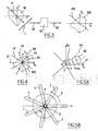
- the figure 1 schematically shows a longitudinal section of the focal plane of a hot spot detection device of the state of the art.
- the hot-spot detection device conventionally comprises four rectangular-shaped detection bars 1 and placed relative to each other to form a regular Greek cross centered on the longitudinal axis 2 of the device.
- the bars 1 are placed in the focal plane of the detection device. Their length is equal to the field of optics, and their width approximately to the diameter of the image spot (percussive response) of the optics.
- the bars 1 are fixed relative to the projectile symbolized by the normal ortho mark 3 itself centered on the axis 2.
- the optical axis 6 of the device is rotated about the axis 2 along the arrow referenced by 5, the optical axis 6 being at a distance R of the axis 2.
- the trajectory of the axis 6 in the focal plane is represented by the circle 4.
- the bars 1 detect a hot spot.
- the detection and positioning of this hot spot relative to the projectile allows the projectile to move towards the hot spot and therefore the target.
- the invention proposes to overcome these disadvantages.
- One of the aims of the invention is to propose a method for reconstructing an image by means of the signals picked up on sensor arrays mounted on a projectile.
- figure 2 whose elements similar to figure 1 carry identical numerical references, schematically represents a section longitudinal axis of a focal plane of a device implementing a method according to the invention.
- a detection device implementing a method according to the invention comprises at least three detection bars 1 of rectangular shape and placed relative to each other in at least three directions non-collinear with each other.
- the detectors are oriented radially towards the axis 2 of the device, and towards the vertices of a regular polygon.
- the bars are thus arranged together in a regular "Y" shape centered on the longitudinal axis 2 of the device.
- the bars 1 are placed in the focal plane of the detection device. Their length is equal to the field of optics, and their width approximately to the diameter of the image spot (percussive response) of the optics.
- the bars 1 are fixed relative to the projectile symbolized by the normal ortho mark 3 itself centered on the axis 2.
- the optical axis 6 of the device rotates about the axis 2 according to the arrow referenced 5 by a router, the optical axis 6 being at a distance R from the axis 2.
- the trajectory of the axis 6 in the focal plane is represented by circle 4.
- angles ⁇ of rotation are given by measuring means connected to the router.
- the optical axis 6 performs a translational movement in front of the bars 1. It is of course also possible, when changing the reference, that the bars 1 perform a translational movement circular to the optical axis 6.
- the figure 3 shows a bar 1 passing in front of the image 30 of the scene - if we take as reference the axes (Ox, Oy) centered on the image 30 - in a direction 31 of displacement in translation.
- the image 30 of the scene is acquired during a step 32, that is to say all along the translation in the direction 31.
- L the operator which makes it possible from an image 30 to obtain the signals coming from the bars 1.
- Im the function of x and y in the focal plane which represents the image of the scene we are trying to obtain.
- the function Im therefore represents the image 30 on the figure 3 .
- the function B is the signals obtained on the bars 1.
- the function B represents the signals 33 of the figure 3 .
- the fact of integrating the entire length of the bar 1 is similar to a measurement acquisition technique used in tomography. Tomography is used in the medical field in particular.
- This measurement acquisition characteristic makes it possible to use a tomographic image reconstruction method.
- equation (1) highlights the linear aspect of the problem and assumes the linearity of the bars.
- a method according to the invention can use a step that is similar to a Radon transform.
- the calculation parameter is the displacement of the next image not ⁇ ⁇ k .
- the figure 4 shows that the image 300 in the Fourier space of an image acquired by arrays in real space is all the better sampled as the number of arrays in real space is important. It is recalled that the direction of sampling in the frequency space is perpendicular to the direction of extension of the bar in real space.
- the figure 4 also shows that width D of the strips occurs as a convolution of the image in frequency space by a disc 50 whose diameter is 1 / D.
- the device for implementing the method according to the invention generally comprises, preferably, seven bars.
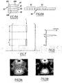
- the Figure 6A thus schematically shows that the image 60 acquired by the bars 1 is divided into pixels referenced by 600. Thus lines are defined, which are referred to as 61, 62, 63 and 64 on the Figure 6A .
- each pixel of the image 60 is performed.
- Each pixel 600 of the image 60 thus bears a number.
- the Figure 6B shows that we then represent the image 600 as a vector 65 by putting one after the other lines 61 to 64 for example.
- a vector B representative of B of equation (1) is constructed by juxtaposing the signals received from each strip 1 after numbering the bars. The juxtaposition of the signals in the vector B is performed according to the numbers of the bars.
- the figure 7 shows that the operator L of equation (1) is represented by its matrix.
- each line of the matrix L corresponds to a current bar i of the focal plane.
- Each column of the matrix L corresponds to a pixel j.
- the intensity of the digitized signal from each strip i for a hot spot centered on the pixel j during a router turn is then transferred in column and for each current pixel j of the focal plane.
- the evolution of this intensity on a bar i during a spinning lathe is shown schematically in FIG. figure 8 .
- equation (1) In general, the system of equation (1) is not invertible and admits an infinity of solutions, because the matrix L is rectangular.
- the performance of a device implementing a method according to the invention will then be conditioned, in addition to the physical characteristics of the device, by the resolution steps used for the linear system, as well as by the relevance of the problem setting for the resolution.
- the dimensions of the bars are (in ⁇ m) 700 ⁇ 100 and the represented plane is a square of 750 ⁇ m side. These dimensions are given as a non-limiting indication and depend on the field size of the optical system.
- a first possible embodiment of a method according to the invention consists in minimizing a quadratic functional instead of directly solving equation (1).
- the quadratic error between the measurements and the expected image is minimized.
- This method is called least squares method by the skilled person.
- the initial image is zero throughout the field of the detectors.
- the threshold depends on the applications and the acquisition modules. In our example, it can be set to 1 ⁇ 2.
- the loop stops after a certain number of iterations or when the reconstituted image is sufficiently resolved to be exploited by the means for processing and guiding the projectile.
- Performing a thresholding of the image makes it possible to avoid the formation of parasitic signals on the image and to ensure a better convergence of the calculation.
- FIGS. 9A to 9D show the results of the first four iterations of a method using the least squares method.
- the image is divided into 1600 pixels.
- the focal plane has two hot spots 91 and 92 of the same intensity and visible in particular on the Figure 9D .
- the calculation takes into account signal processing, including the elimination of a low frequency component.
- the Figure 9A is the reconstructed image after an iteration with a threshold equal to 1 ⁇ 2.
- the Figure 9B is the reconstituted image after two iterations with a threshold equal to 1 ⁇ 4.
- the Figure 9C is the reconstructed image after three iterations with a threshold equal to 1/6.
- the Figure 9D is the reconstructed image after four iterations with a threshold equal to 1/8.
- a second possible embodiment of a method according to the invention consists in using a resolution method of the maximization or minimization type of a functional under stress.
- Such under-determination may occur when the measurements are of a limited number, ie when the bars are rapidly acquiring the scene, or when the measurements under certain incidences are not accessible or exploitable.
- a method of maximizing or minimizing a constrained functional can of course be used in all cases of acquisition.
- ALT Algebraic Reconstruction Technique
- MART Multiplicative Algebraic Reconstruction Technique
- a method of the MART type is used.
- This method of resolution can be interpreted as a minimization or a maximization under stress with an entropic criterion.
- a method according to the invention converges the solution to a maximum entropy of the image with the constraint given by equation (1).
- a set of measurements is corrected at each iteration to obtain a solution quickly.
- the set of measurements to be corrected is then moved at each iteration according to the displacement of the bar considered with respect to the scene.
- the correction of the image during the iteration n + 1 of the process is carried out substantially by a multiplication of the image I not k obtained at pixel k after correction during an iteration n by the ratio of the signal B n received by a given strip at this pixel k during the iteration n on the one hand to the signal R n reconstituted over the entire array given during the iteration n on the other hand.
- I not + 1 k I not k ⁇ B not R not
- R n represents the signal that gives the image reconstituted on the bar considered.
- n denotes a matrix index, it describes the indices of each matrix cyclically, modulo the size of the matrix.
- the index n is thus not limited by the size of the matrices in the iterations.
- the nk ⁇ ⁇ nk ⁇ nk makes it possible to carry out an averaging of the correction on all the pixels of the bar. This ensures a conservation of energy during the different iterations and the convergence of the iterative process is allowed.
- the iterations are stopped when a number of iterations is reached or when the reconstituted image is sufficiently resolved to be exploited by the means for processing and guiding the projectile.
- the figure 10 thus shows the image of a pattern with remarkable patterns 100.
- the figure 11 shows the reconstructed image of the test pattern figure 10 after a dozen iterations of the process. It clearly distinguishes the reconstituted images 110 of the patterns 100.
- the figure 4 clearly shows that the high frequencies are less likely to be perceived by the sampling given by the lines 41 to 45 for example, since they are moving away from the center of the marker (Ofx, Ofy).
- the disc 50 is detected, in the worst case, when it is tangent to two straight at the same time.
- f max ⁇ 1 D we wish to have: f max ⁇ 1 D to be able to observe more than one period of the sinusoid in real space. 1 f max ⁇ D must therefore be less than 1.
- n is preferably greater than or equal to 7.
- the device for implementing a method according to the invention thus preferably comprises seven strips 1 equally distributed, as shown in FIG. Figure 5B .
Landscapes
- Engineering & Computer Science (AREA)
- Chemical & Material Sciences (AREA)
- Combustion & Propulsion (AREA)
- General Engineering & Computer Science (AREA)
- Physics & Mathematics (AREA)
- Electromagnetism (AREA)
- Apparatus For Radiation Diagnosis (AREA)
- Image Processing (AREA)
- Image Analysis (AREA)
Claims (10)
- Verfahren zum Wiederaufbau eines Bildes (Im), das mit auf einem Projektil montierten Detektorstäben (1) erfasst wurde, dadurch gekennzeichnet, dass der für das Bild (Im) repräsentative Vektor aus dem für die Signale (B) der Stäbe (1) repräsentativen Vektor durch Auflösung des linearen Systems wieder aufgebaut wird derart, dass:

wobei L die Matrix ist, die die von jedem Stab für alle Pixel des Bildes ausgehenden Signale übernimmt. - Verfahren nach Anspruch 1, dadurch gekennzeichnet, dass es die Schritte umfasst, gemäß denen:- die Stäbe nummeriert werden und der Vektor B durch Aneinanderreihung der von jedem Stab (1) empfangenen Signale in Abhängigkeit von der Stabnummer konstruiert wird,- die Ebene, in der sich die Stäbe befinden, in Pixel unterteilt wird, wobei sich die Pixel am Schnittpunkt von Zeilen und Spalten befinden und der Vektor Im durch Aneinanderreihen der Zeilen der derart unterteilten Ebene konstruiert wird, und- jeder Koeffizient Li,j der Matrix L durch Übertragung in die Spalte für jedes laufende Pixel j der Intensität des digitalisierten Signals jedes Stabs i für einen auf das Pixel j zentrierten warmen Punkt konstruiert wird, wobei jede Zeile von L einem Stab und jede Spalte einem Pixel entspricht.
- Verfahren nach einem der Ansprüche 1 oder 2, dadurch gekennzeichnet, dass die Auflösung des linearen Systems eine Methode vom Typ Minimierung einer quadratischen Funktion verwendet.
- Verfahren nach Anspruch 3, dadurch gekennzeichnet, dass die Methode der Auflösung eine Methode der kleinsten Quadrate ist und dass die Funktion vom Typ 1/2 · Im t · Lt - L · Im - Im t - Lt - B ist,
wobei Im t , Lt die transponierte Matrix von Im und von L bezeichnen. - Verfahren nach Anspruch 4, dadurch gekennzeichnet, dass die Methode der kleinsten Quadrate einen Schritt umfasst:- der Initialisierung, gemäß der das Bild auf dem gesamten Feld der Stäbe annulliert wird,- der Definition einer Ausgangsschwelle, und- der Schleifenbildung, die darin besteht, durchzuführen:wobei die Schleife am Ende einer bestimmten Anzahl von Iterationen stoppt oder wenn die Auflösung des wieder aufgebauten Bildes ausreichend ist, um durch Bearbeitungs- und Lenkungsmittel des Projektils verwendet zu werden.- einen Abstieg je konjugierten Gradienten,- eine Bildsegmentierung im Schwellwertverfahren und eine Nullstellung der Signale des Bildes, deren Intensität sich unterhalb des Schwellwerts befindet, und- ein Absenken der Schwelle,
- Verfahren nach einem der Ansprüche 1 oder 2, dadurch gekennzeichnet, dass die Auflösung des linearen Systems eine Methode vom Typ Minimierung oder Maximierung einer Funktion unter Constraint verwendet.
- Verfahren nach Anspruch 6, dadurch gekennzeichnet, dass die Methode der Auflösung eine Maximierung der Entropie des Bildes mit dem Constraint L · Im = B ist.
- Verfahren nach Anspruch 7, dadurch gekennzeichnet, dass die Methode der Auflösung eine multiplikative algebraische Rekonstruktionstechnik "MART" verwendet.
- Vorrichtung zum Bildwiederaufbau, dadurch gekennzeichnet, dass sie Detektorstäbe und Verarbeitungsmittel umfasst, die imstande sind, das Verfahren nach einem der Ansprüche 1 bis 8 umzusetzen.
- Vorrichtung nach Anspruch 9, dadurch gekennzeichnet, dass sie sieben im Verhältnis zur Achse der Vorrichtung radial angeordnete, zueinander nicht kolineare Stäbe umfasst.
Applications Claiming Priority (2)
| Application Number | Priority Date | Filing Date | Title |
|---|---|---|---|
| FR0314089 | 2003-12-01 | ||
| FR0314089A FR2863079B1 (fr) | 2003-12-01 | 2003-12-01 | Procede et dispositif de reconstitution d'image sur des barrettes de detecteurs |
Publications (2)
| Publication Number | Publication Date |
|---|---|
| EP1538416A1 EP1538416A1 (de) | 2005-06-08 |
| EP1538416B1 true EP1538416B1 (de) | 2010-07-28 |
Family
ID=34451701
Family Applications (1)
| Application Number | Title | Priority Date | Filing Date |
|---|---|---|---|
| EP04292843A Expired - Lifetime EP1538416B1 (de) | 2003-12-01 | 2004-12-01 | Verfahren und Vorrichtung zum Wiederaufbau von Bildern auf Detektorstäben |
Country Status (4)
| Country | Link |
|---|---|
| EP (1) | EP1538416B1 (de) |
| AT (1) | ATE475855T1 (de) |
| DE (1) | DE602004028331D1 (de) |
| FR (1) | FR2863079B1 (de) |
Family Cites Families (3)
| Publication number | Priority date | Publication date | Assignee | Title |
|---|---|---|---|---|
| DE4208516C2 (de) * | 1992-03-17 | 1994-03-03 | Deutsche Aerospace | Bilderzeugendes Suchkopfsystem |
| US5529262A (en) * | 1993-06-23 | 1996-06-25 | Horwath; Tibor G. | Guidance seeker for small spinning projectiles |
| US5669581A (en) * | 1994-04-11 | 1997-09-23 | Aerojet-General Corporation | Spin-stabilized guided projectile |
-
2003
- 2003-12-01 FR FR0314089A patent/FR2863079B1/fr not_active Expired - Fee Related
-
2004
- 2004-12-01 EP EP04292843A patent/EP1538416B1/de not_active Expired - Lifetime
- 2004-12-01 AT AT04292843T patent/ATE475855T1/de not_active IP Right Cessation
- 2004-12-01 DE DE602004028331T patent/DE602004028331D1/de not_active Expired - Lifetime
Also Published As
| Publication number | Publication date |
|---|---|
| EP1538416A1 (de) | 2005-06-08 |
| DE602004028331D1 (de) | 2010-09-09 |
| ATE475855T1 (de) | 2010-08-15 |
| FR2863079B1 (fr) | 2006-03-03 |
| FR2863079A1 (fr) | 2005-06-03 |
Similar Documents
| Publication | Publication Date | Title |
|---|---|---|
| EP1003011B1 (de) | Optische Bestimmung der relativen Positionen von Körpern in einem Raum | |
| EP0004227B1 (de) | Einrichtung zur optoelektrischen Detektion und zur Bestimmung der Winkelablage eines leuchtenden Objekts, sowie deren Verwendung | |
| US9927510B2 (en) | Star tracker | |
| EP2495531B1 (de) | Verfahren zum Messen der Stabilität einer Sichtlinie und entsprechender Sternsensor | |
| EP1012549B1 (de) | Vorrichtung und verfahren zur optischen wellenfrontanalyse | |
| CA2917066A1 (fr) | Procede et systeme de surveillance d'une phase de transfert d'un satellite d'une orbite initiale vers une orbite de mission | |
| FR3085481A1 (fr) | Procede de detection et de caracterisation par ultrasons de defauts dans un materiau heterogene | |
| EP1354212B1 (de) | Verfahren zur bestimmung aerodynamischer parameter und verfahren zur erkennung eines ausfalls einer sonde, die zur bestimmung aerodynamischer parameter benutzt wird | |
| EP1472563B1 (de) | Satellitengestütztes optisches beobachtungsinstrument mit zwei teleskopen | |
| EP1538416B1 (de) | Verfahren und Vorrichtung zum Wiederaufbau von Bildern auf Detektorstäben | |
| EP2208099B1 (de) | Einrichtung zur messung der defekte eines abbildungsinstruments mit zwei optoelektronischen sensoren | |
| EP2733929B1 (de) | Verfahren und System zur Echtzeitbestimmung einer Anzahl zu summierender Signale | |
| FR2981149A1 (fr) | Aeronef comprenant un senseur optique diurne et nocturne, et procede de mesure d'attitude associe | |
| EP1666923A1 (de) | Verfahren zur Lokalisierung beweglicher magnetischer Ziele | |
| FR2690738A1 (fr) | Capteur solaire pour axes des Z destiné à déterminer la position des satellites. | |
| EP4437362B1 (de) | Verfahren zur ortung eines ziels mittels eines detektors mit mehreren quadranten | |
| EP3018625B1 (de) | Kalibrierungsverfahren eines zielsystems | |
| EP2520916A1 (de) | Multispektrales Scanteleskop mit Wellenfrontanalysemitteln. | |
| EP2113460B1 (de) | Charakterisierungsverfahren von Schwingungen für einen Beobachtungssatelliten | |
| EP1371958A1 (de) | Vorrichtung und Verfahren zum Extrahieren der spectralen Signatur eines punkförmigen Ziels | |
| FR3113739A1 (fr) | Procédé et dispositif de suivi adaptatif d'un objet basés sur la technologie LIDAR | |
| FR3116401A1 (fr) | Procédé de traitement d’un signal GNSS en vue d’atténuer au moins un signal de brouillage | |
| EP2373962B1 (de) | Luftfahrtfahrzeug | |
| WO2023057729A1 (fr) | Procédé et dispositif pour détecter un leurrage de signaux satellite | |
| FR3033405A1 (fr) | Procede et dispositif d'etalonnage au sol d'un instrument optique |
Legal Events
| Date | Code | Title | Description |
|---|---|---|---|
| PUAI | Public reference made under article 153(3) epc to a published international application that has entered the european phase |
Free format text: ORIGINAL CODE: 0009012 |
|
| AK | Designated contracting states |
Kind code of ref document: A1 Designated state(s): AT BE BG CH CY CZ DE DK EE ES FI FR GB GR HU IE IS IT LI LT LU MC NL PL PT RO SE SI SK TR |
|
| AX | Request for extension of the european patent |
Extension state: AL BA HR LV MK YU |
|
| 17P | Request for examination filed |
Effective date: 20051205 |
|
| AKX | Designation fees paid |
Designated state(s): AT BE BG CH CY CZ DE DK EE ES FI FR GB GR HU IE IS IT LI LT LU MC NL PL PT RO SE SI SK TR |
|
| RAP1 | Party data changed (applicant data changed or rights of an application transferred) |
Owner name: SAGEM DEFENSE SECURITE |
|
| GRAP | Despatch of communication of intention to grant a patent |
Free format text: ORIGINAL CODE: EPIDOSNIGR1 |
|
| GRAS | Grant fee paid |
Free format text: ORIGINAL CODE: EPIDOSNIGR3 |
|
| GRAA | (expected) grant |
Free format text: ORIGINAL CODE: 0009210 |
|
| AK | Designated contracting states |
Kind code of ref document: B1 Designated state(s): AT BE BG CH CY CZ DE DK EE ES FI FR GB GR HU IE IS IT LI LT LU MC NL PL PT RO SE SI SK TR |
|
| REG | Reference to a national code |
Ref country code: GB Ref legal event code: FG4D Free format text: NOT ENGLISH |
|
| REG | Reference to a national code |
Ref country code: CH Ref legal event code: EP |
|
| REG | Reference to a national code |
Ref country code: IE Ref legal event code: FG4D Free format text: LANGUAGE OF EP DOCUMENT: FRENCH |
|
| REF | Corresponds to: |
Ref document number: 602004028331 Country of ref document: DE Date of ref document: 20100909 Kind code of ref document: P |
|
| REG | Reference to a national code |
Ref country code: NL Ref legal event code: VDEP Effective date: 20100728 |
|
| LTIE | Lt: invalidation of european patent or patent extension |
Effective date: 20100728 |
|
| PG25 | Lapsed in a contracting state [announced via postgrant information from national office to epo] |
Ref country code: NL Free format text: LAPSE BECAUSE OF FAILURE TO SUBMIT A TRANSLATION OF THE DESCRIPTION OR TO PAY THE FEE WITHIN THE PRESCRIBED TIME-LIMIT Effective date: 20100728 Ref country code: LT Free format text: LAPSE BECAUSE OF FAILURE TO SUBMIT A TRANSLATION OF THE DESCRIPTION OR TO PAY THE FEE WITHIN THE PRESCRIBED TIME-LIMIT Effective date: 20100728 Ref country code: FI Free format text: LAPSE BECAUSE OF FAILURE TO SUBMIT A TRANSLATION OF THE DESCRIPTION OR TO PAY THE FEE WITHIN THE PRESCRIBED TIME-LIMIT Effective date: 20100728 Ref country code: AT Free format text: LAPSE BECAUSE OF FAILURE TO SUBMIT A TRANSLATION OF THE DESCRIPTION OR TO PAY THE FEE WITHIN THE PRESCRIBED TIME-LIMIT Effective date: 20100728 |
|
| PG25 | Lapsed in a contracting state [announced via postgrant information from national office to epo] |
Ref country code: BG Free format text: LAPSE BECAUSE OF FAILURE TO SUBMIT A TRANSLATION OF THE DESCRIPTION OR TO PAY THE FEE WITHIN THE PRESCRIBED TIME-LIMIT Effective date: 20101028 Ref country code: SI Free format text: LAPSE BECAUSE OF FAILURE TO SUBMIT A TRANSLATION OF THE DESCRIPTION OR TO PAY THE FEE WITHIN THE PRESCRIBED TIME-LIMIT Effective date: 20100728 Ref country code: PT Free format text: LAPSE BECAUSE OF FAILURE TO SUBMIT A TRANSLATION OF THE DESCRIPTION OR TO PAY THE FEE WITHIN THE PRESCRIBED TIME-LIMIT Effective date: 20101129 Ref country code: PL Free format text: LAPSE BECAUSE OF FAILURE TO SUBMIT A TRANSLATION OF THE DESCRIPTION OR TO PAY THE FEE WITHIN THE PRESCRIBED TIME-LIMIT Effective date: 20100728 Ref country code: IS Free format text: LAPSE BECAUSE OF FAILURE TO SUBMIT A TRANSLATION OF THE DESCRIPTION OR TO PAY THE FEE WITHIN THE PRESCRIBED TIME-LIMIT Effective date: 20101128 Ref country code: CY Free format text: LAPSE BECAUSE OF FAILURE TO SUBMIT A TRANSLATION OF THE DESCRIPTION OR TO PAY THE FEE WITHIN THE PRESCRIBED TIME-LIMIT Effective date: 20100728 |
|
| REG | Reference to a national code |
Ref country code: IE Ref legal event code: FD4D |
|
| PG25 | Lapsed in a contracting state [announced via postgrant information from national office to epo] |
Ref country code: GR Free format text: LAPSE BECAUSE OF FAILURE TO SUBMIT A TRANSLATION OF THE DESCRIPTION OR TO PAY THE FEE WITHIN THE PRESCRIBED TIME-LIMIT Effective date: 20101029 Ref country code: SE Free format text: LAPSE BECAUSE OF FAILURE TO SUBMIT A TRANSLATION OF THE DESCRIPTION OR TO PAY THE FEE WITHIN THE PRESCRIBED TIME-LIMIT Effective date: 20100728 |
|
| PGFP | Annual fee paid to national office [announced via postgrant information from national office to epo] |
Ref country code: IT Payment date: 20101127 Year of fee payment: 7 |
|
| PG25 | Lapsed in a contracting state [announced via postgrant information from national office to epo] |
Ref country code: IE Free format text: LAPSE BECAUSE OF FAILURE TO SUBMIT A TRANSLATION OF THE DESCRIPTION OR TO PAY THE FEE WITHIN THE PRESCRIBED TIME-LIMIT Effective date: 20100728 Ref country code: DK Free format text: LAPSE BECAUSE OF FAILURE TO SUBMIT A TRANSLATION OF THE DESCRIPTION OR TO PAY THE FEE WITHIN THE PRESCRIBED TIME-LIMIT Effective date: 20100728 |
|
| PG25 | Lapsed in a contracting state [announced via postgrant information from national office to epo] |
Ref country code: RO Free format text: LAPSE BECAUSE OF FAILURE TO SUBMIT A TRANSLATION OF THE DESCRIPTION OR TO PAY THE FEE WITHIN THE PRESCRIBED TIME-LIMIT Effective date: 20100728 Ref country code: CZ Free format text: LAPSE BECAUSE OF FAILURE TO SUBMIT A TRANSLATION OF THE DESCRIPTION OR TO PAY THE FEE WITHIN THE PRESCRIBED TIME-LIMIT Effective date: 20100728 Ref country code: SK Free format text: LAPSE BECAUSE OF FAILURE TO SUBMIT A TRANSLATION OF THE DESCRIPTION OR TO PAY THE FEE WITHIN THE PRESCRIBED TIME-LIMIT Effective date: 20100728 Ref country code: EE Free format text: LAPSE BECAUSE OF FAILURE TO SUBMIT A TRANSLATION OF THE DESCRIPTION OR TO PAY THE FEE WITHIN THE PRESCRIBED TIME-LIMIT Effective date: 20100728 |
|
| PLBE | No opposition filed within time limit |
Free format text: ORIGINAL CODE: 0009261 |
|
| STAA | Information on the status of an ep patent application or granted ep patent |
Free format text: STATUS: NO OPPOSITION FILED WITHIN TIME LIMIT |
|
| BERE | Be: lapsed |
Owner name: SAGEM DEFENSE SECURITE Effective date: 20101231 |
|
| PG25 | Lapsed in a contracting state [announced via postgrant information from national office to epo] |
Ref country code: ES Free format text: LAPSE BECAUSE OF FAILURE TO SUBMIT A TRANSLATION OF THE DESCRIPTION OR TO PAY THE FEE WITHIN THE PRESCRIBED TIME-LIMIT Effective date: 20101108 |
|
| 26N | No opposition filed |
Effective date: 20110429 |
|
| PG25 | Lapsed in a contracting state [announced via postgrant information from national office to epo] |
Ref country code: MC Free format text: LAPSE BECAUSE OF NON-PAYMENT OF DUE FEES Effective date: 20101231 |
|
| REG | Reference to a national code |
Ref country code: CH Ref legal event code: PL |
|
| GBPC | Gb: european patent ceased through non-payment of renewal fee |
Effective date: 20101201 |
|
| REG | Reference to a national code |
Ref country code: DE Ref legal event code: R097 Ref document number: 602004028331 Country of ref document: DE Effective date: 20110429 |
|
| REG | Reference to a national code |
Ref country code: FR Ref legal event code: ST Effective date: 20110831 |
|
| PG25 | Lapsed in a contracting state [announced via postgrant information from national office to epo] |
Ref country code: BE Free format text: LAPSE BECAUSE OF NON-PAYMENT OF DUE FEES Effective date: 20101231 |
|
| PG25 | Lapsed in a contracting state [announced via postgrant information from national office to epo] |
Ref country code: LI Free format text: LAPSE BECAUSE OF NON-PAYMENT OF DUE FEES Effective date: 20101231 Ref country code: CH Free format text: LAPSE BECAUSE OF NON-PAYMENT OF DUE FEES Effective date: 20101231 Ref country code: FR Free format text: LAPSE BECAUSE OF NON-PAYMENT OF DUE FEES Effective date: 20110103 |
|
| REG | Reference to a national code |
Ref country code: DE Ref legal event code: R119 Ref document number: 602004028331 Country of ref document: DE Effective date: 20110701 |
|
| PG25 | Lapsed in a contracting state [announced via postgrant information from national office to epo] |
Ref country code: GB Free format text: LAPSE BECAUSE OF NON-PAYMENT OF DUE FEES Effective date: 20101201 Ref country code: DE Free format text: LAPSE BECAUSE OF NON-PAYMENT OF DUE FEES Effective date: 20110701 |
|
| PG25 | Lapsed in a contracting state [announced via postgrant information from national office to epo] |
Ref country code: LU Free format text: LAPSE BECAUSE OF NON-PAYMENT OF DUE FEES Effective date: 20101201 Ref country code: HU Free format text: LAPSE BECAUSE OF FAILURE TO SUBMIT A TRANSLATION OF THE DESCRIPTION OR TO PAY THE FEE WITHIN THE PRESCRIBED TIME-LIMIT Effective date: 20110129 |
|
| PG25 | Lapsed in a contracting state [announced via postgrant information from national office to epo] |
Ref country code: TR Free format text: LAPSE BECAUSE OF FAILURE TO SUBMIT A TRANSLATION OF THE DESCRIPTION OR TO PAY THE FEE WITHIN THE PRESCRIBED TIME-LIMIT Effective date: 20100728 |
|
| PG25 | Lapsed in a contracting state [announced via postgrant information from national office to epo] |
Ref country code: IT Free format text: LAPSE BECAUSE OF NON-PAYMENT OF DUE FEES Effective date: 20111201 |