EP1538394A2 - Profilrahmen-Leuchte - Google Patents
Profilrahmen-Leuchte Download PDFInfo
- Publication number
- EP1538394A2 EP1538394A2 EP04028447A EP04028447A EP1538394A2 EP 1538394 A2 EP1538394 A2 EP 1538394A2 EP 04028447 A EP04028447 A EP 04028447A EP 04028447 A EP04028447 A EP 04028447A EP 1538394 A2 EP1538394 A2 EP 1538394A2
- Authority
- EP
- European Patent Office
- Prior art keywords
- profile frame
- light according
- frame light
- profile
- light source
- Prior art date
- Legal status (The legal status is an assumption and is not a legal conclusion. Google has not performed a legal analysis and makes no representation as to the accuracy of the status listed.)
- Granted
Links
Images


Classifications
-
- F—MECHANICAL ENGINEERING; LIGHTING; HEATING; WEAPONS; BLASTING
- F21—LIGHTING
- F21V—FUNCTIONAL FEATURES OR DETAILS OF LIGHTING DEVICES OR SYSTEMS THEREOF; STRUCTURAL COMBINATIONS OF LIGHTING DEVICES WITH OTHER ARTICLES, NOT OTHERWISE PROVIDED FOR
- F21V19/00—Fastening of light sources or lamp holders
- F21V19/0075—Fastening of light sources or lamp holders of tubular light sources, e.g. ring-shaped fluorescent light sources
- F21V19/008—Fastening of light sources or lamp holders of tubular light sources, e.g. ring-shaped fluorescent light sources of straight tubular light sources, e.g. straight fluorescent tubes, soffit lamps
-
- F—MECHANICAL ENGINEERING; LIGHTING; HEATING; WEAPONS; BLASTING
- F21—LIGHTING
- F21S—NON-PORTABLE LIGHTING DEVICES; SYSTEMS THEREOF; VEHICLE LIGHTING DEVICES SPECIALLY ADAPTED FOR VEHICLE EXTERIORS
- F21S8/00—Lighting devices intended for fixed installation
- F21S8/04—Lighting devices intended for fixed installation intended only for mounting on a ceiling or the like overhead structures
- F21S8/06—Lighting devices intended for fixed installation intended only for mounting on a ceiling or the like overhead structures by suspension
-
- F—MECHANICAL ENGINEERING; LIGHTING; HEATING; WEAPONS; BLASTING
- F21—LIGHTING
- F21V—FUNCTIONAL FEATURES OR DETAILS OF LIGHTING DEVICES OR SYSTEMS THEREOF; STRUCTURAL COMBINATIONS OF LIGHTING DEVICES WITH OTHER ARTICLES, NOT OTHERWISE PROVIDED FOR
- F21V11/00—Screens not covered by groups F21V1/00, F21V3/00, F21V7/00 or F21V9/00
- F21V11/06—Screens not covered by groups F21V1/00, F21V3/00, F21V7/00 or F21V9/00 using crossed laminae or strips, e.g. grid-shaped louvers; using lattices or honeycombs
-
- F—MECHANICAL ENGINEERING; LIGHTING; HEATING; WEAPONS; BLASTING
- F21—LIGHTING
- F21V—FUNCTIONAL FEATURES OR DETAILS OF LIGHTING DEVICES OR SYSTEMS THEREOF; STRUCTURAL COMBINATIONS OF LIGHTING DEVICES WITH OTHER ARTICLES, NOT OTHERWISE PROVIDED FOR
- F21V15/00—Protecting lighting devices from damage
- F21V15/01—Housings, e.g. material or assembling of housing parts
-
- F—MECHANICAL ENGINEERING; LIGHTING; HEATING; WEAPONS; BLASTING
- F21—LIGHTING
- F21V—FUNCTIONAL FEATURES OR DETAILS OF LIGHTING DEVICES OR SYSTEMS THEREOF; STRUCTURAL COMBINATIONS OF LIGHTING DEVICES WITH OTHER ARTICLES, NOT OTHERWISE PROVIDED FOR
- F21V17/00—Fastening of component parts of lighting devices, e.g. shades, globes, refractors, reflectors, filters, screens, grids or protective cages
- F21V17/06—Fastening of component parts of lighting devices, e.g. shades, globes, refractors, reflectors, filters, screens, grids or protective cages the fastening being onto or by the lampholder
-
- F—MECHANICAL ENGINEERING; LIGHTING; HEATING; WEAPONS; BLASTING
- F21—LIGHTING
- F21V—FUNCTIONAL FEATURES OR DETAILS OF LIGHTING DEVICES OR SYSTEMS THEREOF; STRUCTURAL COMBINATIONS OF LIGHTING DEVICES WITH OTHER ARTICLES, NOT OTHERWISE PROVIDED FOR
- F21V17/00—Fastening of component parts of lighting devices, e.g. shades, globes, refractors, reflectors, filters, screens, grids or protective cages
- F21V17/10—Fastening of component parts of lighting devices, e.g. shades, globes, refractors, reflectors, filters, screens, grids or protective cages characterised by specific fastening means or way of fastening
- F21V17/16—Fastening of component parts of lighting devices, e.g. shades, globes, refractors, reflectors, filters, screens, grids or protective cages characterised by specific fastening means or way of fastening by deformation of parts; Snap action mounting
- F21V17/164—Fastening of component parts of lighting devices, e.g. shades, globes, refractors, reflectors, filters, screens, grids or protective cages characterised by specific fastening means or way of fastening by deformation of parts; Snap action mounting the parts being subjected to bending, e.g. snap joints
-
- F—MECHANICAL ENGINEERING; LIGHTING; HEATING; WEAPONS; BLASTING
- F21—LIGHTING
- F21V—FUNCTIONAL FEATURES OR DETAILS OF LIGHTING DEVICES OR SYSTEMS THEREOF; STRUCTURAL COMBINATIONS OF LIGHTING DEVICES WITH OTHER ARTICLES, NOT OTHERWISE PROVIDED FOR
- F21V7/00—Reflectors for light sources
- F21V7/0008—Reflectors for light sources providing for indirect lighting
- F21V7/0016—Reflectors for light sources providing for indirect lighting on lighting devices that also provide for direct lighting, e.g. by means of independent light sources, by splitting of the light beam, by switching between both lighting modes
-
- F—MECHANICAL ENGINEERING; LIGHTING; HEATING; WEAPONS; BLASTING
- F21—LIGHTING
- F21V—FUNCTIONAL FEATURES OR DETAILS OF LIGHTING DEVICES OR SYSTEMS THEREOF; STRUCTURAL COMBINATIONS OF LIGHTING DEVICES WITH OTHER ARTICLES, NOT OTHERWISE PROVIDED FOR
- F21V7/00—Reflectors for light sources
- F21V7/0025—Combination of two or more reflectors for a single light source
-
- F—MECHANICAL ENGINEERING; LIGHTING; HEATING; WEAPONS; BLASTING
- F21—LIGHTING
- F21S—NON-PORTABLE LIGHTING DEVICES; SYSTEMS THEREOF; VEHICLE LIGHTING DEVICES SPECIALLY ADAPTED FOR VEHICLE EXTERIORS
- F21S8/00—Lighting devices intended for fixed installation
- F21S8/02—Lighting devices intended for fixed installation of recess-mounted type, e.g. downlighters
-
- F—MECHANICAL ENGINEERING; LIGHTING; HEATING; WEAPONS; BLASTING
- F21—LIGHTING
- F21Y—INDEXING SCHEME ASSOCIATED WITH SUBCLASSES F21K, F21L, F21S and F21V, RELATING TO THE FORM OR THE KIND OF THE LIGHT SOURCES OR OF THE COLOUR OF THE LIGHT EMITTED
- F21Y2103/00—Elongate light sources, e.g. fluorescent tubes
Definitions
- the present invention relates to a so-called. Profile frame light according to the Preamble of claim 1.
- Such lights are usually using a cable suspension in one arranged at a certain distance from the ceiling of a room to be illuminated.
- the Housing of the luminaire is formed from a plurality of profile elements, leading to a Body frame are composed.
- one Light source arranged, which at least a portion of its light to the bottom emits.
- the present invention is therefore based on the object, a Ability to specify a light source in the simplest possible way in one Profile frame light to arrange.
- the object is achieved by a luminaire, which has the features of claim 1 has dissolved.
- the luminaire according to the invention initially comprises at least one Profile element existing frame-shaped luminaire housing and at least one elongated light source located at two opposite positions of the Housing is held.
- two socket holders which are detachably connected to the profile element and at least one in each case Carry bulb holder for holding one end of the light source.
- the frame holders can be designed latchable in particular with the profile element.
- the inventive use of the two frame holder allows a very easy and quick installation of the luminaire.
- the light source now easily clipped into the frame-like luminaire housing will have to make without further assembly steps. That's the way it is, for example no longer necessary, holding elements for the light source to the luminaire housing tightening.
- the Holder according to the invention preferably substantially U-shaped bent, wherein arranged on a first U-leg locking projections / recesses are, which with corresponding locking recesses / projections of the profile element cooperate, and wherein the second U-leg of the socket holder the Carries lamp socket.
- the second U-leg several locking holes have, with which latching pins located on the lamp socket are latched.
- a lamination element can in each case be attached to the frame holders be arranged, which arranged one below the lamp socket Has laminating plate. This plate ensures that from the bottom not on the version and thus on the version led to the version Luminaire wiring can be looked.
- Profile frame light is - seen in the direction of radiation - in front of the light source
- Light influencing element arranged in the form of a grid arrangement, which has a plurality of openings provided for light emission openings.
- Locking arrangements are already well known and are used to emitted light from the light source to a predetermined angular range to restrict and thus to avoid glare effects.
- the latching arrangement of several Single modules exist, which along the light source to the latching arrangement are joined together. Since this will be guaranteed for lighting reasons must be that the individual modules are close to each other, can on the front pages
- the grid arrangement may be provided each biasing elements, which the modules compress in the longitudinal direction.
- the Preload elements are also located on the socket holders.
- Another development of the invention is concerned with the design of the Grid arrangement.
- This preferably has a longitudinal direction extending rear reflector, which is intended to be a part of the Light source radiated light to reflect against the emission direction.
- the passage openings are arranged, which are destined to the remaining part of the radiated from the light source Let light pass through in the direction of radiation.
- the back reflector ensures that at least a small portion of the radiated from the light source Light is thrown upwards against the main radiation direction and thus a complementary indirect lighting is created.
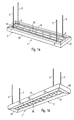
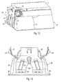
- FIG. 1a and 1b The illustrated in Figures 1a and 1b and generally with the reference numeral 1 provided grid frame light consists of a frame-shaped Luminaire housing 2, which via a cable suspension to a (not shown) Ceiling of the room to be illuminated is to be fastened.
- the luminaire housing 2 is formed from four profile elements 10, which cut to fermentation and to the frame-like structure are joined together.
- profile elements 10 is aluminum extrusion profiles, whose structure is described in more detail later is.
- the suspension of the lamp 1 is carried out by means of four suspension cables 3, the each to be fixed to the ceiling.
- the Suspension cables 3 At its far end of the ceiling, the Suspension cables 3 each have an anchoring element 4, which in a Suspension of the profile elements 10 used and thus anchored in the housing 2 is.
- a Lighting arrangement which consists of two elongated light sources 55 in the form of two gas discharge lamps and on the other hand from a grid arrangement 20, whose structure will be described later in more detail.
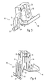
- the attachment the light sources 55 on the lamp housing 2 is effected by means of two Holder according to the invention, which will now be described with reference to FIGS to 6 will be explained in more detail.
- the profile element 10 is substantially C-shaped and designed to with the holder holder 30, whose embodiment in particular the figures 3 to 5 can be removed, to lock.
- the profile element 10 in his Opening area two latching recesses 11, 12, in which corresponding Locking projections 33, 35 of the socket holder 30 engage.
- the frame holder 30, is stamped from spring steel, is bent in a U-shape, the Locking projections 33, 35 are arranged on a first U-leg 31. Again Representation can be seen in Figure 5, this first U-leg 31 in its lower portion bifurcated split into two sections 32, whose lower ends are bent to two locking lugs 33.
- the upper locking projection 35 In contrast, 31 is obtained by a punching of the first U-leg.
- the Both lower portions 32 of the first U-leg 31 point beyond also two bent spring tongues 34, whose function later will be explained in more detail.
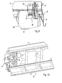
- the second U-leg 36 of the socket holder 30 is for holding two Lampholders 50 provided and has for this purpose a plurality of locking holes 39, in which engage on the back of the sockets 50 arranged locking pins 51, such as in particular the illustration in Figure 2 can be removed.
- lamination element 40th This consists in Essentially from a laminating plate 42, from which a latching head 41 after extending above, for latching with one of the second U-leg 36 of the Socket holder 30 is provided inwardly bent projection 37.
- a safe Arrangement of the lamination element 40 is further by two in the Laminated plate 42 provided projections 43 ensures, which is located on the Support lower edge of the second U-leg 36 of the socket holder 30.
- FIG Laminating plate 42 then disposed below the lamp sockets 50 and prevents from the bottom of the lamp holders 50 and thus to the Lamps led lighting wiring can be seen.
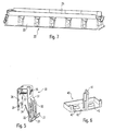
- FIG Lamp according to the invention a - in the emission direction - in front of the light sources 55th arranged latching arrangement 20 to the emitted light down restrict certain angular ranges.
- the embodiment of this locking arrangement 20 will now be explained in more detail with reference to Figure 7 and Figure 10.
- the latching arrangement 20 first of a cross-section approximately semicircular back reflector 21, which surrounds the lamps in the mounting position at least partially and causes at least a small portion of the output from the lamps 55 Light is reflected to the top.
- the luminaire according to the invention achieved so that both a direct and an indirect lighting.
- a plurality of passage openings 23 are arranged, which are intended to allow light to pass in the direction of radiation.
- a pot-shaped reflector 22 on, for example, a round or a rectangular light exit opening with may have a size of about 40 mm to 60 mm in diameter.
- the juxtaposed pot reflectors 22 give the impression of a Series arrangement of several halogen lamps, whereby the lamp a special, gives a visually interesting appearance.
- the Topfreflektoren 22 arranged over a parallel to the lamps 55 Connection plate 24 connected together.
- the individual elements of the reflector assembly 20, so the back reflector 21, the Topfreflektoren 22 and the connecting plate 24 can each also be formed partially transparent, whereby additional optical effects are achieved can.
- the illustrated reflector assembly 20 is - as can be seen in Fig. 1b - preferably of a plurality of individual modules 25, which are longitudinal to the entire Reflector assembly 20 are joined together.
- An injection molding tool for producing a one-piece However, reflector arrangement over the entire length of the luminaire would be over many times more expensive than the production of several smaller individual modules 25.
- the latch assembly 20 is not otherwise through the grid holder 30 is held. Instead, the individual modules 25 are only in the Housing frame inserted and lie with lateral projections 26 and 27 (see FIG. 11 or FIG. 13) on corresponding bearing surfaces of the two lateral ones Profile elements 10 on.
- a luminaire is thus created that has a very elegant appearance and also achieved visually appealing lighting effects.
- the Assembly of the luminaire in total is compared to previous profile frame lights much easier.
Landscapes
- Engineering & Computer Science (AREA)
- General Engineering & Computer Science (AREA)
- Fastening Of Light Sources Or Lamp Holders (AREA)
- Non-Portable Lighting Devices Or Systems Thereof (AREA)
- Glass Compositions (AREA)
- Paper (AREA)
Abstract
Description
- Figuren 1a und 1b
- eine erfindungsgemäß ausgestaltete Profilrahmen-Leuchte in perspektivischen Ansichten;
- Figur 2
- die Anordnung eines erfindungsgemäßen Fassungshalters an einem Profilelement in Schnittdarstellung;
- Figuren 3 und 4
- den Fassungshalter mit einem daran befestigten Kaschierungsmodul in zwei perspektivischen Darstellungen;
- Figur 5
- den erfindungsgemäßen Fassungshalter;
- Figur 6
- ein Kaschierungselement;
- Figur 7
- eine Rasteranordnung mit einem an einer Stirnseite angeordneten Fassungshalter;
- Figur 8
- eine vergrößerte Darstellung der Anordnung des Fassungshalters an der Stirnseite der Rasteranordnung;
- Figur 9
- die Darstellung von Figur 8 im Schnitt;
- Figur 10
- ein Rastermodul mit einem Fassungshalter in perspektivischer Ansicht von oben und
- Figuren 11 bis 13
- verschiedene Ansichten der Anordnung eines Fassungshalters an der Rasteranordnung
Claims (24)
- Profilrahmen-Leuchte (1) mit einem aus mindestens einem Profilelement (10) bestehenden rahmenförmigen Leuchtengehäuse (2) sowie mindestens einer länglichen Lichtquelle (55), die an zwei einander gegenüberliegenden Positionen des Leuchtengehäuses (2) gehalten ist,
gekennzeichnet durch
zwei Fassungshalter (30), welche lösbar mit dem Profilelement (10) verbunden sind und jeweils mindestens eine Lampenfassung (50) zum Halten eines Endes der Lichtquelle (55) tragen. - Profilrahmen-Leuchte nach Anspruch 1,
dadurch gekennzeichnet, dass die Fassungshalter (30) mit dem Profilelement (10) verrastbar sind. - Profilrahmen-Leuchte nach Anspruch 2,
dadurch gekennzeichnet, dass die Fassungshalter (30) jeweils mehrere Rastvorsprünge/-rücktritte (33, 35) aufweisen, welche mit entsprechenden Rastrücktritten/-vorsprüngen (11, 12) des Profilelements (10) zusammenwirken. - Profilrahmen-Leuchte nach Anspruch 3,
dadurch gekennzeichnet, dass die Fassungshalter (30) im wesentlichen U-förmig gebogen sind, wobei an einem ersten U-Schenkel (31) die Rastvorsprünge/-rücktritte (33, 35) angeordnet sind und der zweite U-Schenkel (36) die Lampenfassung (50) trägt. - Profilrahmen-Leuchte nach Anspruch 4,
dadurch gekennzeichnet, dass der zweite U-Schenkel (36) mehrere Rastbohrungen (39) aufweist, mit denen an der Lampenfassung (50) befindliche Raststifte (51) verrastbar sind. - Profilrahmen-Leuchte nach einem der vorherigen Ansprüche,
dadurch gekennzeichnet, dass an den Fassungshaltern (30) jeweils ein Kaschierungselement (40) angeordnet ist, welches eine unterhalb der Lampenfassung (50) angeordnete Kaschierungsplatte (42) aufweist. - Profilrahmen-Leuchte nach Anspruch 6,
dadurch gekennzeichnet, dass das Kaschierungselement (40) einen Rastkopf (41) aufweist, über welchen es mit dem entsprechenden Fassungshalter (30) verbindbar ist. - Profilrahmen-Leuchte nach einem der vorherigen Ansprüche,
dadurch gekennzeichnet, dass - in Abstrahlrichtung gesehen - vor der Lichtquelle (55) eine Rasteranordnung (20) angeordnet ist, welche mehrere zur Lichtabstrahlung vorgesehene Durchtrittsöffnungen (23) aufweist. - Profilrahmen-Leuchte nach Anspruch 8,
dadurch gekennzeichnet, dass die Rasteranordnung (20) aus mehreren Einzelmodulen (25) besteht, welche entlang der Lichtquelle (55) zu der Rasteranordnung (20) zusammengefügt sind. - Profilrahmen-Leuchte nach Anspruch 9,
dadurch gekennzeichnet, dass die Einzelmodule (25) durch an den Stirnseiten der Rasteranordnung (20) befindliche Vorspannelemente (34) in Längsrichtung zusammengedrückt werden. - Profilrahmen-Leuchte nach Anspruch 10,
dadurch gekennzeichnet, dass sich die Vorspannelemente (34) an den Fassungshaltern (30) befinden. - Profilrahmen-Leuchte nach Anspruch 4 oder 5 und Anspruch 11,
dadurch gekennzeichnet, dass der erste U-Schenkel (31) der Fassungshalter (30) gabelförmig aufgespalten ist,
wobei an jedem Teilbereich (32) des ersten U-Schenkels (31) ein Vorspannelement in Form einer Klemmfeder (34) angeordnet ist. - Profilrahmen-Leuchte nach einem der Ansprüche 8 bis 12,
dadurch gekennzeichnet, dass die Rasteranordnung (20) einen sich in Längsrichtung erstreckenden Rückreflektor (21) aufweist, der dazu bestimmt ist, einen Teil des von der Lichtquelle (55) abgestrahlten Lichtes entgegen der Abstrahlrichtung zu reflektieren,
wobei in dem Rückreflektor (21) die Durchtrittsöffnungen (23) angeordnet sind, die dazu bestimmt sind, einen Teil des von der Lichtquelle (55) abgestrahlten Lichtes in Abstrahlrichtung hindurchtreten zu lassen. - Profilrahmen-Leuchte nach Anspruch 13,
dadurch gekennzeichnet, dass sich an die Durchtrittsöffnungen (23) in dem Rückreflektor (21) in Abstrahlrichtung Topfreflektoren (22) anschließen. - Profilrahmen-Leuchte nach Anspruch 14,
dadurch gekennzeichnet, dass der Rückreflektor (21) und die Topfreflektoren (22) einstückig miteinander verbunden sind. - Profilrahmen-Leuchte nach Anspruch 14 oder 15,
dadurch gekennzeichnet, daß die Topfreflektoren (22) an ihren Randbereichen über eine parallel zur Lichtquelle (55) angeordnete Verbindungsplatte (24) miteinander verbunden sind. - Profilrahmen-Leuchte nach Anspruch 16,
dadurch gekennzeichnet, daß die Verbindungsplatte (24) einstückig mit den Topfreflektoren (22) verbunden ist. - Profilrahmen-Leuchte nach einem der Ansprüche 14 bis 17,
dadurch gekennzeichnet, daß die Topfreflektoren (22) ein runde oder rechteckige Lichtaustrittsöffnung aufweisen. - Profilrahmen-Leuchte nach einem der Ansprüche 14 bis 18,
dadurch gekennzeichnet, daß die Lichtaustrittsöffnungen der Topfreflektoren (22) eine Größe von ca. 40 - 60 mm im Durchmesser aufweisen - Profilrahmen-Leuchte nach einem der Ansprüche 13 bis 19,
dadurch gekennzeichnet, daß der Rückreflektor (21) die Lichtquelle (55) zumindest teilweise umgreift. - Profilrahmen-Leuchte nach Anspruch 20,
dadurch gekennzeichnet, daß der Rückreflektor (21) im Querschnitt halbkreisförmig ist. - Profilrahmen-Leuchte nach einem der Ansprüche 13 bis 21,
dadurch gekennzeichnet, daß der Rückreflektor (21) zumindest teilweise transparent ist. - Profilrahmen-Leuchte nach einem der vorherigen Ansprüche,
dadurch gekennzeichnet, dass diese zwei parallel verlaufende Lichtquellen (55) aufweist,
wobei an den beiden Fassungshaltern (30) jeweils zwei Lampenfassungen (50) angeordnet sind. - Profilrahmen-Leuchte nach einem der vorherigen Ansprüche,
dadurch gekennzeichnet, dass die Fassungshalter (30) aus Federblech gestanzt sind.
Applications Claiming Priority (2)
| Application Number | Priority Date | Filing Date | Title |
|---|---|---|---|
| DE10356064 | 2003-12-01 | ||
| DE10356064A DE10356064A1 (de) | 2003-12-01 | 2003-12-01 | Profilrahmen-Leuchte |
Publications (3)
| Publication Number | Publication Date |
|---|---|
| EP1538394A2 true EP1538394A2 (de) | 2005-06-08 |
| EP1538394A3 EP1538394A3 (de) | 2006-08-30 |
| EP1538394B1 EP1538394B1 (de) | 2008-02-13 |
Family
ID=34442380
Family Applications (1)
| Application Number | Title | Priority Date | Filing Date |
|---|---|---|---|
| EP04028447A Expired - Lifetime EP1538394B1 (de) | 2003-12-01 | 2004-12-01 | Profilrahmen-Leuchte |
Country Status (3)
| Country | Link |
|---|---|
| EP (1) | EP1538394B1 (de) |
| AT (1) | ATE386235T1 (de) |
| DE (2) | DE10356064A1 (de) |
Cited By (2)
| Publication number | Priority date | Publication date | Assignee | Title |
|---|---|---|---|---|
| WO2009021581A1 (de) * | 2007-08-10 | 2009-02-19 | Zumtobel Lighting Gmbh | Leuchte mit raster zur lichtabgabe |
| US10731808B2 (en) | 2014-03-27 | 2020-08-04 | Signify Holding B.V. | Luminaire with multiple light emissive surfaces |
Families Citing this family (1)
| Publication number | Priority date | Publication date | Assignee | Title |
|---|---|---|---|---|
| DE102012221454B4 (de) | 2012-11-23 | 2022-06-23 | Zumtobel Lighting Gmbh | Leuchte mit einem Leuchtengehäuse, das ein Profilelement umfasst |
Family Cites Families (3)
| Publication number | Priority date | Publication date | Assignee | Title |
|---|---|---|---|---|
| DE2336418A1 (de) * | 1973-07-13 | 1975-02-20 | Erco Leuchten | Deckenleuchte in abgehaengter decke |
| DE4416110C2 (de) * | 1994-05-06 | 1996-10-02 | Lenneper Gmbh & Co Kg | Tragschiene mit Geräteträger für elektrische Installationen und Leuchtmittel |
| DE10151958A1 (de) * | 2001-10-22 | 2003-04-30 | Zumtobel Staff Gmbh | Leuchte mit mehreren Topfreflektoren |
-
2003
- 2003-12-01 DE DE10356064A patent/DE10356064A1/de not_active Ceased
-
2004
- 2004-12-01 EP EP04028447A patent/EP1538394B1/de not_active Expired - Lifetime
- 2004-12-01 DE DE502004006179T patent/DE502004006179D1/de not_active Expired - Lifetime
- 2004-12-01 AT AT04028447T patent/ATE386235T1/de active
Cited By (2)
| Publication number | Priority date | Publication date | Assignee | Title |
|---|---|---|---|---|
| WO2009021581A1 (de) * | 2007-08-10 | 2009-02-19 | Zumtobel Lighting Gmbh | Leuchte mit raster zur lichtabgabe |
| US10731808B2 (en) | 2014-03-27 | 2020-08-04 | Signify Holding B.V. | Luminaire with multiple light emissive surfaces |
Also Published As
| Publication number | Publication date |
|---|---|
| EP1538394B1 (de) | 2008-02-13 |
| DE10356064A1 (de) | 2005-06-23 |
| EP1538394A3 (de) | 2006-08-30 |
| ATE386235T1 (de) | 2008-03-15 |
| DE502004006179D1 (de) | 2008-03-27 |
Similar Documents
| Publication | Publication Date | Title |
|---|---|---|
| EP1040295B1 (de) | Deckenanbauleuchte mit einem scheibenförmigen lichtleiter | |
| EP0897511B1 (de) | Lichtbandfähige langfeldleuchte | |
| EP3270047B1 (de) | Flachleuchte | |
| DE102009009653A1 (de) | Leuchte mit wannenförmigem Gehäuse und lichtdurchlässiger Abdeckung | |
| EP2913582B1 (de) | Diffusor für eine Leuchte | |
| EP2711750B1 (de) | LED-Leuchte mit Lichtleiterplatte | |
| EP1538394B1 (de) | Profilrahmen-Leuchte | |
| EP0795719B1 (de) | Modular aufgebaute Leuchteneinheit | |
| EP2924337B1 (de) | Leuchte mit einem lichtleiter zur erzeugung von entblendetem, teilflächigen licht | |
| EP2175188B1 (de) | Leuchte | |
| EP1132679B1 (de) | Leuchtensystem | |
| EP2472178A1 (de) | Einbauleuchte | |
| DE19721340A1 (de) | Leuchte | |
| EP3477195B1 (de) | Langfeldleuchte, insbesondere lichtbandleuchte, sowie daraus aufgebautes lichtband | |
| EP2085684B1 (de) | Leuchte mit selbsttragender Reflektoreinheit | |
| EP1616124B1 (de) | Rasterleuchte | |
| EP1519103B1 (de) | Leuchte mit rohrförmiger Gasentladungslampe | |
| EP1779029B1 (de) | Rasteranordnung | |
| DE102016104448A1 (de) | Flachleuchte | |
| EP1473512B1 (de) | Leuchte | |
| DE202012100628U1 (de) | Leuchte mit einem länglichen Gehäuse und Anbauelement hierfür | |
| EP1845305A1 (de) | Leuchte mit Gehäuse mit flexiblem Wandmaterial | |
| EP1132681B1 (de) | Tragschienensystem | |
| EP3364099B1 (de) | Modulare leuchte mit direkt- und indirektanteil | |
| DE202022103416U1 (de) | Rettungszeichenleuchte mit zusätzlicher Rettungswegbeleuchtung |
Legal Events
| Date | Code | Title | Description |
|---|---|---|---|
| PUAI | Public reference made under article 153(3) epc to a published international application that has entered the european phase |
Free format text: ORIGINAL CODE: 0009012 |
|
| AK | Designated contracting states |
Kind code of ref document: A2 Designated state(s): AT BE BG CH CY CZ DE DK EE ES FI FR GB GR HU IE IS IT LI LT LU MC NL PL PT RO SE SI SK TR |
|
| AX | Request for extension of the european patent |
Extension state: AL BA HR LV MK YU |
|
| PUAL | Search report despatched |
Free format text: ORIGINAL CODE: 0009013 |
|
| AK | Designated contracting states |
Kind code of ref document: A3 Designated state(s): AT BE BG CH CY CZ DE DK EE ES FI FR GB GR HU IE IS IT LI LT LU MC NL PL PT RO SE SI SK TR |
|
| AX | Request for extension of the european patent |
Extension state: AL BA HR LV MK YU |
|
| 17P | Request for examination filed |
Effective date: 20070228 |
|
| 17Q | First examination report despatched |
Effective date: 20070327 |
|
| AKX | Designation fees paid |
Designated state(s): AT BE BG CH CY CZ DE DK EE ES FI FR GB GR HU IE IS IT LI LT LU MC NL PL PT RO SE SI SK TR |
|
| GRAP | Despatch of communication of intention to grant a patent |
Free format text: ORIGINAL CODE: EPIDOSNIGR1 |
|
| RAP1 | Party data changed (applicant data changed or rights of an application transferred) |
Owner name: ZUMTOBEL LIGHTING GMBH |
|
| GRAS | Grant fee paid |
Free format text: ORIGINAL CODE: EPIDOSNIGR3 |
|
| GRAA | (expected) grant |
Free format text: ORIGINAL CODE: 0009210 |
|
| AK | Designated contracting states |
Kind code of ref document: B1 Designated state(s): AT BE BG CH CY CZ DE DK EE ES FI FR GB GR HU IE IS IT LI LT LU MC NL PL PT RO SE SI SK TR |
|
| REG | Reference to a national code |
Ref country code: GB Ref legal event code: FG4D Free format text: NOT ENGLISH |
|
| REG | Reference to a national code |
Ref country code: CH Ref legal event code: EP |
|
| REG | Reference to a national code |
Ref country code: IE Ref legal event code: FG4D Free format text: LANGUAGE OF EP DOCUMENT: GERMAN |
|
| REF | Corresponds to: |
Ref document number: 502004006179 Country of ref document: DE Date of ref document: 20080327 Kind code of ref document: P |
|
| REG | Reference to a national code |
Ref country code: CH Ref legal event code: NV Representative=s name: A. BRAUN, BRAUN, HERITIER, ESCHMANN AG PATENTANWAE |
|
| REG | Reference to a national code |
Ref country code: CH Ref legal event code: PFA Owner name: ZUMTOBEL LIGHTING GMBH Free format text: ZUMTOBEL LIGHTING GMBH#ACHTZEHN-MORGEN-WEG 2-4#61250 USINGEN (DE) -TRANSFER TO- ZUMTOBEL LIGHTING GMBH#ACHTZEHN-MORGEN-WEG 2-4#61250 USINGEN (DE) |
|
| PG25 | Lapsed in a contracting state [announced via postgrant information from national office to epo] |
Ref country code: FI Free format text: LAPSE BECAUSE OF FAILURE TO SUBMIT A TRANSLATION OF THE DESCRIPTION OR TO PAY THE FEE WITHIN THE PRESCRIBED TIME-LIMIT Effective date: 20080213 Ref country code: ES Free format text: LAPSE BECAUSE OF FAILURE TO SUBMIT A TRANSLATION OF THE DESCRIPTION OR TO PAY THE FEE WITHIN THE PRESCRIBED TIME-LIMIT Effective date: 20080524 Ref country code: IS Free format text: LAPSE BECAUSE OF FAILURE TO SUBMIT A TRANSLATION OF THE DESCRIPTION OR TO PAY THE FEE WITHIN THE PRESCRIBED TIME-LIMIT Effective date: 20080613 |
|
| NLV1 | Nl: lapsed or annulled due to failure to fulfill the requirements of art. 29p and 29m of the patents act | ||
| PG25 | Lapsed in a contracting state [announced via postgrant information from national office to epo] |
Ref country code: SI Free format text: LAPSE BECAUSE OF FAILURE TO SUBMIT A TRANSLATION OF THE DESCRIPTION OR TO PAY THE FEE WITHIN THE PRESCRIBED TIME-LIMIT Effective date: 20080213 Ref country code: PL Free format text: LAPSE BECAUSE OF FAILURE TO SUBMIT A TRANSLATION OF THE DESCRIPTION OR TO PAY THE FEE WITHIN THE PRESCRIBED TIME-LIMIT Effective date: 20080213 |
|
| REG | Reference to a national code |
Ref country code: IE Ref legal event code: FD4D |
|
| PG25 | Lapsed in a contracting state [announced via postgrant information from national office to epo] |
Ref country code: IE Free format text: LAPSE BECAUSE OF FAILURE TO SUBMIT A TRANSLATION OF THE DESCRIPTION OR TO PAY THE FEE WITHIN THE PRESCRIBED TIME-LIMIT Effective date: 20080213 Ref country code: NL Free format text: LAPSE BECAUSE OF FAILURE TO SUBMIT A TRANSLATION OF THE DESCRIPTION OR TO PAY THE FEE WITHIN THE PRESCRIBED TIME-LIMIT Effective date: 20080213 Ref country code: PT Free format text: LAPSE BECAUSE OF FAILURE TO SUBMIT A TRANSLATION OF THE DESCRIPTION OR TO PAY THE FEE WITHIN THE PRESCRIBED TIME-LIMIT Effective date: 20080714 Ref country code: SK Free format text: LAPSE BECAUSE OF FAILURE TO SUBMIT A TRANSLATION OF THE DESCRIPTION OR TO PAY THE FEE WITHIN THE PRESCRIBED TIME-LIMIT Effective date: 20080213 Ref country code: SE Free format text: LAPSE BECAUSE OF FAILURE TO SUBMIT A TRANSLATION OF THE DESCRIPTION OR TO PAY THE FEE WITHIN THE PRESCRIBED TIME-LIMIT Effective date: 20080513 Ref country code: CZ Free format text: LAPSE BECAUSE OF FAILURE TO SUBMIT A TRANSLATION OF THE DESCRIPTION OR TO PAY THE FEE WITHIN THE PRESCRIBED TIME-LIMIT Effective date: 20080213 Ref country code: DK Free format text: LAPSE BECAUSE OF FAILURE TO SUBMIT A TRANSLATION OF THE DESCRIPTION OR TO PAY THE FEE WITHIN THE PRESCRIBED TIME-LIMIT Effective date: 20080213 |
|
| PG25 | Lapsed in a contracting state [announced via postgrant information from national office to epo] |
Ref country code: RO Free format text: LAPSE BECAUSE OF FAILURE TO SUBMIT A TRANSLATION OF THE DESCRIPTION OR TO PAY THE FEE WITHIN THE PRESCRIBED TIME-LIMIT Effective date: 20080213 |
|
| EN | Fr: translation not filed | ||
| PLBE | No opposition filed within time limit |
Free format text: ORIGINAL CODE: 0009261 |
|
| STAA | Information on the status of an ep patent application or granted ep patent |
Free format text: STATUS: NO OPPOSITION FILED WITHIN TIME LIMIT |
|
| 26N | No opposition filed |
Effective date: 20081114 |
|
| PG25 | Lapsed in a contracting state [announced via postgrant information from national office to epo] |
Ref country code: LT Free format text: LAPSE BECAUSE OF FAILURE TO SUBMIT A TRANSLATION OF THE DESCRIPTION OR TO PAY THE FEE WITHIN THE PRESCRIBED TIME-LIMIT Effective date: 20080213 |
|
| PG25 | Lapsed in a contracting state [announced via postgrant information from national office to epo] |
Ref country code: FR Free format text: LAPSE BECAUSE OF FAILURE TO SUBMIT A TRANSLATION OF THE DESCRIPTION OR TO PAY THE FEE WITHIN THE PRESCRIBED TIME-LIMIT Effective date: 20081205 Ref country code: BG Free format text: LAPSE BECAUSE OF FAILURE TO SUBMIT A TRANSLATION OF THE DESCRIPTION OR TO PAY THE FEE WITHIN THE PRESCRIBED TIME-LIMIT Effective date: 20080513 Ref country code: EE Free format text: LAPSE BECAUSE OF FAILURE TO SUBMIT A TRANSLATION OF THE DESCRIPTION OR TO PAY THE FEE WITHIN THE PRESCRIBED TIME-LIMIT Effective date: 20080213 |
|
| BERE | Be: lapsed |
Owner name: ZUMTOBEL LIGHTING G.M.B.H. Effective date: 20081231 |
|
| PG25 | Lapsed in a contracting state [announced via postgrant information from national office to epo] |
Ref country code: MC Free format text: LAPSE BECAUSE OF NON-PAYMENT OF DUE FEES Effective date: 20081231 Ref country code: CY Free format text: LAPSE BECAUSE OF FAILURE TO SUBMIT A TRANSLATION OF THE DESCRIPTION OR TO PAY THE FEE WITHIN THE PRESCRIBED TIME-LIMIT Effective date: 20080213 |
|
| PG25 | Lapsed in a contracting state [announced via postgrant information from national office to epo] |
Ref country code: IT Free format text: LAPSE BECAUSE OF FAILURE TO SUBMIT A TRANSLATION OF THE DESCRIPTION OR TO PAY THE FEE WITHIN THE PRESCRIBED TIME-LIMIT Effective date: 20080213 |
|
| PG25 | Lapsed in a contracting state [announced via postgrant information from national office to epo] |
Ref country code: BE Free format text: LAPSE BECAUSE OF NON-PAYMENT OF DUE FEES Effective date: 20081231 |
|
| PG25 | Lapsed in a contracting state [announced via postgrant information from national office to epo] |
Ref country code: HU Free format text: LAPSE BECAUSE OF FAILURE TO SUBMIT A TRANSLATION OF THE DESCRIPTION OR TO PAY THE FEE WITHIN THE PRESCRIBED TIME-LIMIT Effective date: 20080814 Ref country code: LU Free format text: LAPSE BECAUSE OF NON-PAYMENT OF DUE FEES Effective date: 20081201 |
|
| PG25 | Lapsed in a contracting state [announced via postgrant information from national office to epo] |
Ref country code: TR Free format text: LAPSE BECAUSE OF FAILURE TO SUBMIT A TRANSLATION OF THE DESCRIPTION OR TO PAY THE FEE WITHIN THE PRESCRIBED TIME-LIMIT Effective date: 20080213 |
|
| PG25 | Lapsed in a contracting state [announced via postgrant information from national office to epo] |
Ref country code: GR Free format text: LAPSE BECAUSE OF FAILURE TO SUBMIT A TRANSLATION OF THE DESCRIPTION OR TO PAY THE FEE WITHIN THE PRESCRIBED TIME-LIMIT Effective date: 20080514 |
|
| PGFP | Annual fee paid to national office [announced via postgrant information from national office to epo] |
Ref country code: CH Payment date: 20131219 Year of fee payment: 10 Ref country code: GB Payment date: 20131227 Year of fee payment: 10 Ref country code: AT Payment date: 20131219 Year of fee payment: 10 |
|
| REG | Reference to a national code |
Ref country code: CH Ref legal event code: PCAR Free format text: NEW ADDRESS: HOLBEINSTRASSE 36-38, 4051 BASEL (CH) |
|
| REG | Reference to a national code |
Ref country code: CH Ref legal event code: PL |
|
| REG | Reference to a national code |
Ref country code: AT Ref legal event code: MM01 Ref document number: 386235 Country of ref document: AT Kind code of ref document: T Effective date: 20141201 |
|
| GBPC | Gb: european patent ceased through non-payment of renewal fee |
Effective date: 20141201 |
|
| PG25 | Lapsed in a contracting state [announced via postgrant information from national office to epo] |
Ref country code: GB Free format text: LAPSE BECAUSE OF NON-PAYMENT OF DUE FEES Effective date: 20141201 Ref country code: LI Free format text: LAPSE BECAUSE OF NON-PAYMENT OF DUE FEES Effective date: 20141231 Ref country code: CH Free format text: LAPSE BECAUSE OF NON-PAYMENT OF DUE FEES Effective date: 20141231 |
|
| PG25 | Lapsed in a contracting state [announced via postgrant information from national office to epo] |
Ref country code: AT Free format text: LAPSE BECAUSE OF NON-PAYMENT OF DUE FEES Effective date: 20141201 |
|
| PGFP | Annual fee paid to national office [announced via postgrant information from national office to epo] |
Ref country code: DE Payment date: 20160302 Year of fee payment: 12 |
|
| REG | Reference to a national code |
Ref country code: DE Ref legal event code: R119 Ref document number: 502004006179 Country of ref document: DE |
|
| PG25 | Lapsed in a contracting state [announced via postgrant information from national office to epo] |
Ref country code: DE Free format text: LAPSE BECAUSE OF NON-PAYMENT OF DUE FEES Effective date: 20170701 |