Technical Field
The present invention relates to a panel hole
cover for sealing a penetration portion of a steering
element in a vehicle or the like, and more
particularly to a technology for improving
operationality in assembling.
Background Art
In a vehicle, the steering wheel is disposed in
the cabin, while the steering gear is disposed in the
engine room or the like. Thus, the steering wheel
and the steering gear are connected by a steering
element (which will be represented by the steering
shaft hereinafter) that passes through a panel called
a body panel or a dash panel, or the partitioning
member between the engine room and the cabin. The
steering shaft is turned upon steering, and a joint
or the like for connection is attached to its end
portion. Accordingly, a relatively large opening (a
steering opening) is formed on the panel through
which the steering shaft is to be inserted. The
steering opening is sealed by a hole cover made of,
for example, a synthetic rubber to prevent rain water,
dust and noises etc. from entering the cabin.
There are various forms of hole covers, and
typical ways of mounting them are disclosed in
Japanese Utility Model Application Laid-Open No. 3-121972
(which will be referred to as the first prior
art hereinafter) and Japanese Patent Application
Laid-Open No. 11-132328 (which will be referred to as
the second prior art hereinafter). In the first
prior art, the tip end portion of a hole cover made
of a synthetic rubber fixed to the panel is
externally fitted on a boss of the steering gear box,
and then that portion is bound by a metal band so as
to be secured. In the second prior art, a hole cover
having the tip end portion fixed to a boss of the
steering gear box is fitted into the steering opening,
and a fitting member on which a guide claw and a
latch claw that engage the steering opening are
mounted is connected to the hole cover.
The above-described conventional hole covers
suffer from various problems related, for example, to
their mounting process, as described below. For
example, in the hole cover of the first prior art, it
is necessary to tighten a screw of the metal band as
a separate part using a tool such as a screw driver.
However, since the tightening site is in the narrow
engine room, the operation is very difficult and
takes significant time especially on the occasion of
inspection or maintenance etc.. On the other hand,
in the hole cover of the second prior art, the guide
claw is inserted in the edge of the steering opening
so as to be positioned, and then the fitting member
is pushed, so that the latch claw fits into the
steering opening. However, since the guide claw and
the latch claw are set in the inner side of the hole
cover, the operating engineer cannot see the guide
claw and the latch claw during the assembling
operation, and the operation is difficult.
In both the prior arts, the hole cover is
connected to a boss of the steering gear box disposed
below the panel, and when the position of the
steering gear box is displaced in the axial direction
relative to the panel, there is a risk that reliable
waterproof performance cannot be achieved. In
addition, the size of the hole cover is relatively
large in accordance with the distance between the
panel and the boss of the steering gear box, and the
hole cover inevitably takes a curved shape due to the
difference between the angle of the panel and the
angle of the boss.
Disclosure of the Invention
The present invention has been made in view of
the above-described circumstances. An object of the
present invention is to provide a hole cover with
which improvement in the assembling operationality is
realized.
To achieve the above-described object, according
to a first aspect of the present invention, there is
provided a hole cover for a vehicle, for covering an
opening on a panel through which a steering element
is to pass, comprising an elastic seal portion having
a steering penetration portion through which said
steering element passes and being in close contact
with a sealing surface formed on the edge of the
opening of said panel, and a plurality of latch
projections adapted to be pressed against said panel
substantially along the axis of said steering element
so as to be caught in a latch recess formed in the
vicinity of said edge of the opening.
According to a second aspect of the present
invention, there is provided a hole cover for a
vehicle, for covering an opening on a panel through
which a steering element is to pass, comprising an
elastic seal portion having a steering penetration
portion through which said steering element passes
and being in close contact with a sealing surface
formed on the edge of the opening of said panel, and
a latch recess adapted to be pressed against said
panel substantially along the axis of said steering
element so that a plurality of latch projections
formed in the vicinity of said edge of the opening
are caught in the latch recess.
In the present invention, for example, when the
hole cover is slid along the steering shaft so as to
be pressed against the steering opening, the latch
projections are caught in the latch recess, so that
mounting of the hole cover is completed.
The hole cover according to the present
invention may be constructed in such a way that when
said latch projections are caught in said latch
recess, at least one of sound and vibration is
produced. With this feature, the operating engineer
can recognize when the hole cover is mounted,
visually or aurally.
The hole cover according to the present
invention may be constructed in such a way that said
elastic sealing portion is in contact with a sealing
surface having a circular shape, and said latch
projections are caught in said latch recess having an
annular shape. With this feature, the operating
engineer can carry out the hole cover mounting
operation without effecting positioning of the hole
cover and the steering opening with respect to the
rotational direction.
In the hole cover according to the present
invention, said steering penetration portion may be
in sliding contact with said steering element in a
rotational direction. With this feature, the hole
cover can be made as a relatively small disk-like
member if the steering penetration portion is
disposed in the vicinity of the steering opening.
The hole cover according to the present
invention may include an elastic deforming portion
that allows movement of said steering penetration
portion relative to said elastic seal portion. With
this feature, positional displacement or vibration of
the steering element can be absorbed by deformation
of the elastic deforming portion.
In the hole cover according to the present
invention, said elastic seal portion may be formed on
a seal body made of an elastic material, and said
latch projection or said latch recess may be formed
on a seal retaining member that is externally fitted
on the seal body. With this feature, the operating
engineer can carry out mounting of the hole cover by
pressing the seal body and the seal retaining member
externally fitted on the steering shaft to the
steering opening sequentially or simultaneously.
In the hole cover according to the present
invention, a retaining member bias means for biasing
said seal retaining member in a direction away from
said panel may be formed on said seal body. With
this feature, the latch projections and the latch
recess are in pressure contact with each other by the
biasing force exerted by the retaining member bias
means, and rattling noise that may caused by
vibration can be suppressed.
In the hole cover according to the present
invention, said latch projection may be exposed in
the assembled state. In this case, the operating
engineer can recognize the mounting state of the hole
cover visually.
According to the present invention, there is
also provided a hole cover for a vehicle, for
covering an opening on a panel through which a
steering element is to pass, comprising an elastic
seal portion having a steering penetration portion
through which said steering element passes and being
in close contact with a sealing surface formed on the
edge of the opening of said panel, and a latch member
adapted to be pressed against said panel
substantially along the axis of said steering element.
Brief Description of the Drawings
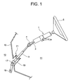
Fig. 1 is a side view showing the cabin side
portion of a steering apparatus according to an
embodiment of the present invention.
Fig. 2 is an exploded perspective view showing a
cover holder barrel and a hole cover in the
embodiment.
Fig. 3 is a half cross sectional side view
showing a mounting state of the hole cover on the
cover holder barrel.
Fig. 4 is an enlarged view showing portion A in
Fig. 3.
Fig. 5 is an enlarged view showing portion B in
Fig. 3.
Fig. 6 illustrates a process of mounting the
hole cover.
Embodiment of the Invention
In the following, an embodiment of the hole
cover according to the present invention will be
described. Fig. 1 is a perspective view showing the
cabin side portion of a steering apparatus according
to the embodiment. The member designated by
reference character 1 in Fig. 1 is a steering column,
which rotatably supports an upper steering shaft 3.
On the upper end of the upper steering shaft 3, a
steering wheel 5 is attached, and an intermediate
steering shaft 9 is connected to the lower end of the
upper steering shaft 3 via a universal joint 7.
The intermediate shaft 9 passes through a panel
15 by which the vehicle's cabin 11 and the engine
room 13 are partitioned, and its lower end is
connected with a lower steering shaft 18 via a
universal joint 17. In Fig. 1, the member designated
by reference character 19 is a cover holder barrel
that constitutes the penetration portion for the
intermediate shaft 9. The cover holder barrel 19 is
fixed on the dash panel 15 in such a way as to
project to the cabin 11 side.
A hole cover 21 is attached to the upper end of
the cover holder barrel 19. Fig. 2 is an exploded
perspective view showing the cover holder barrel 19
and the hole cover 21. Fig. 3 is an enlarged half
cross sectional side view showing the state in which
the hole cover 21 is attached to the cover holder
barrel 19. As shown in Figs. 2 and 3, the hole cover
21 according to this embodiment is composed of a
disk-like seal body 23 produced by molding a
synthetic rubber and a circular seal retaining ring
(or a seal retaining member) 25. As shown in Fig. 3,
an annular metal stiffener 27 is integrally formed in
the seal body 23.
On the seal body 23, a steering penetration
cylinder (or a steering penetration portion) 31
having a cylindrical shape through which the
intermediate shaft 9 is to pass is formed at the
center thereof, and a sealing cylinder 33 also having
a cylindrical shape to be fitted into the end portion
(or the edge of the opening) of the cover holder
barrel 19 is formed on the outer periphery thereof.
The steering penetration cylinder 31 and the sealing
cylinder 33 are joined by paired first and second
elastic deforming rings (deforming portions) 35 and
37 each having a substantially V-shaped cross section,
so that they can be displaced relative to each other
in the radial direction within a certain range.
The inner circumference of the penetration
cylinder 31 is formed as an elastic sealing surface
41 to be in sliding contact with the intermediate
shaft 9. As shown in Fig. 4, the sealing cylinder 33
includes a first flange portion 47 having an elastic
sealing surface 45 in contact with a sealing surface
43 of the cover holding barrel 19 and a second flange
portion 49 in close contact and integrated with the
first flange portion 47. The aforementioned second
elastic deforming ring 37 is integrally joined with
the second flange portion 49. In this embodiment,
the first flange portion 47 and the second flange
portion 49 are constructed as separate members for
reasons of molding (to form a space between the first
and second elastic deforming rings 35 and 37).
As shown in Fig. 4, which is an enlarged view
showing portion A in Fig. 3, an annular lip for
assembling 53 is provided outside the elastic sealing
surface 45 on the first flange portion 47. The lip
51 is in elastic contact with the sealing surface 43.
On the rear surface (i.e. the right side surface in
Fig. 3) of the first flange 47, a pair of projections
for assembling 53 that penetrate the second flange
portion 49 and the seal retaining ring 25 are
provided at intervals of 180°. The projection for
assembling 53 has a securing portion 55 formed on its
base end side. The securing portion 55 secures the
second flange portion 49 and the seal retaining ring
25. As shown in Fig. 4, annular waterproof lips 57
are formed on the outer circumferential surface of
the sealing cylinder 33. The waterproof lips 57 are
in elastic contact with the inner circumferential
surface of the cover holder barrel 19. Although two
waterproof lips 57 are provided in this embodiment,
the number of the waterproof lips 57 may be one or
more than two.
On the seal retaining ring 25, there is provided
three holding tongues 61 projecting toward the front
side (toward the left in Fig. 3) at intervals of 120°.
As shown in Fig. 5 (an enlarged view showing part B
in Fig. 3), latch claws (latch projections) 65 to be
caught in an annular groove (a latch recess) 63
formed on the outer circumferential surface of the
cover holder barrel 19 are integrally formed on the
respective holding tongues 61. The seal retaining
ring 25 has four elongated holes 67 formed at
intervals of 90°.
In the following, the operation of this
embodiment will be described.
In mounting the steering apparatus on the
vehicle body, the operating engineer inserts the
intermediate shaft 9, on which the seal body 23 and
the seal retaining ring 25 have been assembled in
advance, into the cover holder barrel 19 from the
cabin 11 side. Next, the operating engineer connects
the intermediate shaft 9 with the lower steering
shaft 18, and then mounts the seal body 23 and the
seal retaining ring 25 sequentially on the cover
holder barrel 19, as shown in Fig.6.
When the seal body 23 is fitted in the cover
holder barrel 19 by the operating engineer, the
waterproof lips 57 of the sealing cylinder 33 is
internally fitted into and comes in elastic contact
with the inner circumferential surface of the cover
holder barrel 19. In addition, the lip for
assembling 51 of the first flange portion 47 comes in
contact with the sealing surface 43 of the cover
holder barrel 19. The elastic sealing surface 45 and
the sealing surface 43 of the cover holder barrel 19
have not come to contact with each other at this
stage.
Next, when the seal retaining ring 25 is
externally fitted on the cover holder barrel 19 by
the operating engineer, the seal body 23 is biased by
the seal retaining ring 25 and pressed against the
cover holder barrel 19. In addition, the latch claws
65 of the holding tongues 61 are caught in the
annular groove 63. In this process, the operating
engineer causes the projection for assembling 53 to
pass through an elongated hole 67 of the seal
retaining ring 25, and then pulls the projection for
assembling 53 backwardly while holding the seal
retaining ring 25. Thus, the seal retaining ring 25
is secured by the securing portion 55 of the
projection for assembling 53, as shown in Fig.4 so
that the seal body 23 and the seal retaining ring 25
are made integral.
In this embodiment, in the state in which the
latch claws 65 of the holding tongues 61 are caught
in the annular groove 63, the first flange portion 47
of the sealing cylinder 33 is pressed by the seal
retaining ring 25 so as to be compressed along the
axial direction, so that the elastic sealing surface
45 comes in close contact with the sealing surface 43
of the cover holder barrel 19. In addition, the
latch claws 65 are pressed against the rear face (the
right end face in Fig. 5) of the annular groove 63 at
a certain pressing force by virtue of an elastic
force of the lip for assembling 51. When the latch
claws 65 are caught in the annular groove 63, the
latch claws 65 impinge against the bottom of the
annular groove 63 to produce sound and vibration,
which tell the operating engineer of completion of
the mounting of the hole cover 21.
As described in the foregoing, in this
embodiment, the cylindrical steering penetration
cylinder 31 through which the intermediate shaft 9 is
to pass is provided at the central portion of the
seal body 23, and so it is possible to construct the
hole cover 21 as a relatively small disk-like member.
Thus, a reduction in the manufacturing cost and the
weight can be realized. In addition, since the latch
claws 65 of the seal retaining ring 25 are adapted to
be caught in the annular groove 63, positioning of
the hole cover 21 with respect to the rotational
direction is no required. Thus, the operationality
is greatly improved. Furthermore, since in the seal
body 23, the steering penetration cylinder 31 and the
sealing cylinder 33 are joined by the first and
second elastic deforming rings 35 and 37 having
elasticity, the closeness of the contact between the
intermediate shaft 9 and the elastic sealing surface
41 is not decreased even if misalignment of the
central axis of the intermediate shaft 9 with the
center of the hole cover 21 occurs or the
intermediate shaft 9 vibrates during rotation.
Therefore, the waterproof and dustproof performance
of the hole cover 21 is not deteriorated. Still
further, since the waterproof lips 57 are in elastic
contact with the inner circumferential surface of the
cover holder barrel 19, the sealing performance can
be ensured even when the seal body 23 is displaced
along the axial direction.
Although a specific embodiment has been
described in the foregoing, modes of the present
invention are not limited to the above-described
embodiment. For example, although in the above-described
embodiment, the cover holder barrel on
which the hole cover is mounted is provided in such a
way as to project to the cabin, it may project to the
engine room. Alternatively, the hole cover may be
directly mounted on the panel without using the cover
holder barrel. Furthermore, although the latch claws
(latch projections) on the seal retaining ring
(panel) are adapted to engage the annular groove
(latch recess) on the cover holder barrel in the
above-described embodiment, this arrangement may be
modified in such a way that a latch projection
provided on the panel side is adapted to engage a
latch recess provided on the hole cover side. Still
further, although in the above-described embodiment,
the seal body and the seal retaining ring are mounted
sequentially, the seal body and the seal retaining
ring may be coupled in advance, or the seal body and
the seal retaining ring may be constructed as an
integral part. Although in the above-described
embodiment, the cover holder barrel (or the edge of
the panel opening) and the hole cover have circular
cross sections, their cross section may be polygonal
or elliptical. In addition, the material of the seal
body and the seal retaining ring, that is, a rubber
and a steel plate, may be replaced by a synthetic
resin and a metal plate other than the steel plate.
Furthermore, the specific structure of the hole cover
and the shape of the constituent parts may be
modified as needed without departing from the spirit
of the present invention.
As per the above, according to the hole cover of
the present invention, when the hole cover is slid
along the steering shaft so as to be pressed against
the steering opening, the latch projections are
caught in the latch recess, so that mounting of the
hole cover is completed.