EP1538374B1 - Dichtungselement - Google Patents
Dichtungselement Download PDFInfo
- Publication number
- EP1538374B1 EP1538374B1 EP04029053A EP04029053A EP1538374B1 EP 1538374 B1 EP1538374 B1 EP 1538374B1 EP 04029053 A EP04029053 A EP 04029053A EP 04029053 A EP04029053 A EP 04029053A EP 1538374 B1 EP1538374 B1 EP 1538374B1
- Authority
- EP
- European Patent Office
- Prior art keywords
- sealing element
- battery
- injection device
- circuit board
- housing
- Prior art date
- Legal status (The legal status is an assumption and is not a legal conclusion. Google has not performed a legal analysis and makes no representation as to the accuracy of the status listed.)
- Expired - Lifetime
Links
Images

Classifications
-
- A—HUMAN NECESSITIES
- A61—MEDICAL OR VETERINARY SCIENCE; HYGIENE
- A61M—DEVICES FOR INTRODUCING MEDIA INTO, OR ONTO, THE BODY; DEVICES FOR TRANSDUCING BODY MEDIA OR FOR TAKING MEDIA FROM THE BODY; DEVICES FOR PRODUCING OR ENDING SLEEP OR STUPOR
- A61M5/00—Devices for bringing media into the body in a subcutaneous, intra-vascular or intramuscular way; Accessories therefor, e.g. filling or cleaning devices, arm-rests
- A61M5/178—Syringes
- A61M5/20—Automatic syringes, e.g. with automatically actuated piston rod, with automatic needle injection, filling automatically
-
- F—MECHANICAL ENGINEERING; LIGHTING; HEATING; WEAPONS; BLASTING
- F16—ENGINEERING ELEMENTS AND UNITS; GENERAL MEASURES FOR PRODUCING AND MAINTAINING EFFECTIVE FUNCTIONING OF MACHINES OR INSTALLATIONS; THERMAL INSULATION IN GENERAL
- F16J—PISTONS; CYLINDERS; SEALINGS
- F16J15/00—Sealings
- F16J15/02—Sealings between relatively-stationary surfaces
- F16J15/06—Sealings between relatively-stationary surfaces with solid packing compressed between sealing surfaces
- F16J15/10—Sealings between relatively-stationary surfaces with solid packing compressed between sealing surfaces with non-metallic packing
- F16J15/104—Sealings between relatively-stationary surfaces with solid packing compressed between sealing surfaces with non-metallic packing characterised by structure
- F16J15/106—Sealings between relatively-stationary surfaces with solid packing compressed between sealing surfaces with non-metallic packing characterised by structure homogeneous
Definitions
- the present invention relates to a sealing member, particularly to a sealing member for an administering device for metered administration of medical substances, such as an injection device or a pen.
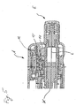
- Figure 5 shows a rear part of a known injection device in a longitudinal section.
- a piston rod K causes the advance of a piston (not shown) in the feed direction (in Figure 5 to the left) to a reservoir outlet, not shown, along the longitudinal axis L, wherein the magnitude of the displacement of the piston rod K determined by a rotation of the adjusting element E and through Pressing the setting element E can be triggered.
- a display element A is provided on which the amount of a set dose is displayed, wherein the set dose is determined by the movement of contact elements 10, which by one or more cams 11 are pressed, which are rotated by a rotational movement of the adjusting element E.
- the sequence of pushing and releasing of the contact elements 10 by the cams 11 makes it possible, with a suitable arrangement of the cams 11 to determine how much the setting element E has been rotated to indicate a set by the rotation dose or amount of active ingredient dispensed on the display element A.
- a small amount of the substance to be dispensed from the pen may be introduced into the so-called modulus of elasticity M or into the circuit provided for evaluating the movement of the contact elements 10 or board and damage the electronics.
- modulus of elasticity M the so-called modulus of elasticity
- circuit provided for evaluating the movement of the contact elements 10 or board and damage the electronics.
- there may be a deterioration of the electronics or provided for the operation of the electronics battery, if such a pen is stored in the refrigerator to ensure the optimal storage of the substance to be dispensed, with a cooling and contraction of the air easily moisture in the electronics can arrive.
- JP2003157740 For example, a non-conductive rubber sealing member is known wherein electrical contact is made with the +/- pole of a battery via conductive wires passing through the sealing member.
- a sealing element for an injection device in such a way that at least one electronic or electrical component in the administering device or the injection device can be sealed with this sealing element, one or more batteries being sealed by the sealing element.
- a contact mat provided for contact elements or pressure pieces is enlarged so that this contact mat can be used as a seal for electrical or electronic components and for sealing a battery.
- the sealing element according to the invention is preferably in one piece or one piece, that is formed from a single element, in which z. B. separate spaces are provided in which to be protected components may be provided, for example the sealing element itself may be wholly or at least partially conductive, for example on a surface thereof, to allow interaction of the component enclosed by the sealing element with the environment.
- the sealing element may be resilient, for example, to transmit an external pressure to a component enclosed by the sealing element, thereby producing, for example, a contact signal.
- the sealing element according to the invention may also cooperate with one or more one-piece or multi-part housing elements in order, for example, to seal components which are, for example, only partially enclosed by the housing in order to protect the components arranged in the housing.
- a housing as well as the sealing element can be rigid or elastic and, for example, provided with a conductive property, so that components sealed by the housing and / or the sealing element can interact with the environment or external elements.
- the housing may be, for example, a so-called module bottom, to which a contact mat is attached as a sealing element, for example, so as to enclose a battery and / or a printed circuit board.
- the housing or the module bottom can have one or more latching elements, for example in the form of latching lugs, in order, for example, to place a module window and connect it firmly to the module base in order to completely seal one or more components.
- the housing or the module bottom may have one or more openings for pressure pieces or contact elements.
- the sealing element is designed so that a battery compartment can be sealed or integrated, the battery can be protected from external substances, such as corrosive liquids, and with a suitable design of the sealing element, which encloses, for example, the circuit board of an electrical circuit, the battery be brought by the sealing element directly into contact with the circuit board, whereby a complex attachment of the battery, for example, by soldering and the provision of contact ironing can be omitted, which significantly simplifies the manufacturing process and cheaper and also leads to a lower susceptibility.
- a recess or recess for the battery in combination with a conductive contact element, such as a graphite barrel, is provided in the sealing element in order to be able to bring areas of the battery, which do not rest directly on a printed circuit board, into electrical contact with the printed circuit board.
- At least one sensing element such as one or more graphite pills, is provided in connection with the sealing element to effect, for example, external pressure on the sealing element, for example by a cam ring, deformation of the sealing element and thereby a sensing element or pressing a graphite pellet onto a circuit board, thereby establishing an electrical contact on the circuit board through which a signal generated by a cam can be detected and evaluated.
- At least one venting channel is provided in the sealing element, so that the at least one sensing element can easily move back and forth without being held in a position by an applied pressure or suction.
- the sealing element according to the invention is preferably made of an elastic or bendable material, such as of a suitable plastic, silicone or rubber and may be wholly or at least partially, for example on certain surface areas, conductive, whereby, for example, an electrical contact with the poles of a Battery or to external components or in a sealed by the sealing element circuit or circuit board can be produced.
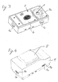
- FIG. 1 shows a module base 1 serving as a housing, on the outer side of which latching lugs 1a are attached for latching to a modular window housing 9 to be fitted, as shown in FIG.
- the module base 1 has in its interior two compartments or spaces 1b and 1c, for example, in the space 1b, a battery can be used and the space 1c for transmitting pressure movements by contact elements or plungers 10 provided in the bottom of the module 1 holes 1d is used.
- spacer bolts 2 are provided, on which, as shown in Figures 2 and 3, a sealing element 3 and a printed circuit board 4 can be placed.
- FIG. 2 shows the module base shown in FIG. 1 with a silicone mat applied thereto as the sealing element 3, wherein the silicone mat 3 has holes corresponding to the lower major outside diameters of the spacer bolts 2, so that the silicone mat 3 is positioned immovably by the spacer bolts 2 on the module base 1.
- the silicone mat 3 has a protruding from the surface of the silicone mat 3 edge 3a, so that through the surface of the silicone mat 3 and the edge 3a, a range is set in which a circuit board 4 can be introduced.
- the silicone mat 3 is made of an elastic non-conductive material and has on its top graphite pills 5, which contact points of the subsequently applied printed circuit board 4 are opposite, so that a of a cam ring 11 through an opening 1 d of the module base 1 pushed through thrust piece 10 on the underside of Silicone mat 3 presses and deforms them so that a provided on top of the silicone mat 3 graphite pill 5 is pushed upward to make contact on the circuit board 4.
- a recess for a battery compartment is provided in the silicone mat 3, in which a graphite barrel 6 is used to make an electrically conductive contact with a Make outside and optionally a bottom of the battery.
- a vent channel 7 is provided between the battery compartment and the graphite pills 5, so that the graphite pills 5 can be easily moved back and forth without being hindered by pressure or Sog bine in their free movement.
- the vent channel 7 facilitates the insertion or removal of a battery in or out of the battery compartment.
- Figure 3 shows the device shown in Figure 2, on which a circuit board 4 is placed with a blackened drawn chip.
- the spacer bolts 2 have in the upper region in each case a portion with a smaller outer diameter, which approximately corresponds to holes in the printed circuit board 4, so that the printed circuit board 4 is positioned by the upper portions of the spacer pin 2.
- the printed circuit board 4 is completely surrounded by the edge 3 a of the silicone mat 3, whereby on the one hand the circuit board 4 is protected from a lateral penetration of substances and on the other hand, the arranged below the circuit board 4 is inserted into the graphite drum 6 completely sealed battery.
- the battery contacted via a provided on the battery contact, which rests directly on the underside of the circuit board 4, a provided on the underside of the circuit board 4 in the region of the arrow P electrode.
- the outside of the battery is connected via the graphite barrel 6 with a likewise provided on the underside of the circuit board 4 in approximately annular dashed line electrode in combination, so that the + and -Pol the battery without soldering and without contact bracket by a simple manufacturing process in electrical connection with the circuit board 4 can be brought.
- the spacer bolts 2 can then be fused by ultrasound, for example, and thus fix the printed circuit board 4 on the module base 1, so that the battery is pressed by the silicone mat 3 to the underside of the printed circuit board 4. Subsequently, the entire module can be programmed and configured, for example, to a desired counting step.
- FIG 4 shows the assembly shown in Figure 3 with an attached module window housing 9, which has recesses 9a, in which the locking lugs 1a of the module base 1 can engage, so as to connect the module window housing 9 fixed to the module base 1 and thus to ensure a secure seal
- the module window housing 9 has a module window 8, which is at least partially transparent and under which, for example, provided on the circuit board 4 LCD display (not shown in Figure 3) may be provided.
- the battery can be mounted without solder joints in the module, whereby no more harmful lead is used for the production of the module.
Landscapes
- Health & Medical Sciences (AREA)
- Engineering & Computer Science (AREA)
- General Engineering & Computer Science (AREA)
- Public Health (AREA)
- Vascular Medicine (AREA)
- Heart & Thoracic Surgery (AREA)
- Hematology (AREA)
- Life Sciences & Earth Sciences (AREA)
- Animal Behavior & Ethology (AREA)
- General Health & Medical Sciences (AREA)
- Anesthesiology (AREA)
- Veterinary Medicine (AREA)
- Biomedical Technology (AREA)
- Mechanical Engineering (AREA)
- Battery Mounting, Suspending (AREA)
- Connection Of Batteries Or Terminals (AREA)
- Fuel-Injection Apparatus (AREA)
- Brushes (AREA)
- Casings For Electric Apparatus (AREA)
- Glass Compositions (AREA)
- Burglar Alarm Systems (AREA)
- Infusion, Injection, And Reservoir Apparatuses (AREA)
Description
- Die vorliegende Erfindung bezieht sich auf ein Dichtungselement, insbesondere auf ein Dichtungselement für eine Verabreichungsvorrichtung zur dosierten Verabreichung medizinischer Substanzen, wie zum Beispiel eine Injektionsvorrichtung bzw. ein Pen.
- Eine Ausführungsform einer bekannten Injektionsvorrichtung ist in der
WO 03/053499 - Figur 5 zeigt einen hinteren Teil eines bekannten Injektionsgeräts in einem Längsschnitt. Eine Kolbenstange K bewirkt den Vorschub eines Kolbens (nicht gezeigt) in die Vorschubrichtung (in Figur 5 nach links) auf einen nicht gezeigten Reservoirauslass zu entlang der Längsachse L, wobei die Größe der Verschiebung der Kolbenstange K durch eine Drehung des Einstellelements E festgelegt und durch Drücken des Einstellelements E ausgelöst werden kann. Um einem Benutzer anzuzeigen welche Dosis er durch Drehung des Einstellelements E eingestellt hat, ist ein Anzeigeelement A vorgesehen, auf welcher die Menge einer eingestellten Dosis dargestellt wird, wobei die eingestellte Dosis anhand der Bewegung von Kontaktelementen 10 ermittelt wird, welche durch eine oder mehrere Nockenscheiben 11 gedrückt werden, die durch eine Drehbewegung des Einstellelements E mitgedreht werden. Die Abfolge des Drückens und Freigebens der Kontaktelemente 10 durch die Nockenscheiben 11 ermöglicht es bei geeigneter Anordnung der Nockenscheiben 11 festzustellen um wie viel das Einstellelement E gedreht wurde, um eine durch die Drehung eingestellte abzugebende Dosis oder Wirkstoffmenge am Anzeigelement A anzuzeigen.
- Jedoch kann durch für die Kontaktelemente 10 vorgesehenen Öffnungen zum Beispiel eine kleine Menge der von dem Pen abzugebenden Substanz in das sogenannte E-Modul M bzw. in die zur Auswertung der Bewegung der Kontaktelemente 10 vorgesehene Schaltung oder Leiterplatte eindringen und die Elektronik beschädigen. Ebenso kann es zu einer Beeinträchtigung der Elektronik bzw. der zum Betrieb der Elektronik vorgesehenen Batterie kommen, falls ein solcher Pen im Kühlschrank gelagert wird, um die optimale Lagerung der abzugebenden Substanz zu gewährleisten, wobei durch eine Abkühlung und ein Zusammenziehen der Luft leicht Feuchtigkeit in die Elektronik gelangen kann.
- Aus
JP2003157740 - Es ist eine Aufgabe der vorliegenden Erfindung eine konstruktive Verbesserung einer Injektionsvorrichtung vorzuschlagen, durch welche die Ausfallsicherheit der Injektionsvorrichtung verbessert wird.
- Diese Aufgabe wird durch den Gegenstand des unabhängigen Patentanspruchs gelöst. Vorteilhafte Ausführungsformen ergeben sich aus den abhängigen Ansprüchen.
- Erfindungsgemäß wird vorgeschlagen ein Dichtungselement für eine Injektionsvorrichtung so auszugestalten, dass mit diesem Dichtungselement mindestens eine elektronische oder elektrische Komponente in der Verabreichungsvorrichtung bzw. dem Injektionsgerät abgedichtet werden kann, wobei eine oder mehrere Batterien durch das Dichtungselement abgedichtet werden. Besonders vorteilhaft wird eine für Kontaktelemente oder Druckstücke vorgesehene Kontaktmatte so vergrößert, dass diese Kontaktmatte als Dichtung für elektrische oder elektronische Komponenten und zur Abdichtung einer Batterie verwendet werden kann.
- Unter dem Begriff "Dichtung" soll im Sinne der Erfindung jedes Element verstanden werden, welches allein oder in Kombination mit einem oder mehreren anderen Elementen, wie zum Beispiel einem Gehäuse und/oder einem Gehäusedeckel, verhindern kann, dass eine Flüssigkeit oder ein Gas wie z. B. Luft in einen bestimmten Raum eindringen kann, so dass in diesem Raum zum Beispiel elektrische oder elektronische Komponenten vor von außen einwirkenden Substanzen geschützt sind.
- Das erfindungsgemäße Dichtungselement ist bevorzugt einstückig bzw. einteilig, also aus einem einzigen Element ausgebildet, in welchem z. B. abgetrennte Räume vorgesehen sind, in welchen zu schützende Komponenten vorgesehen sein können, wobei zum Beispiel das Dichtungselement selbst vollständig oder zumindest zum Teil, zum Beispiel an einer Oberfläche davon, leitend ausgebildet sein kann, um eine Wechselwirkung der von dem Dichtungselement eingeschlossenen Komponente mit der Umgebung zu ermöglichen. Ebenso kann das Dichtungselement elastisch sein, um zum Beispiel einen externen Druck auf eine von dem Dichtungselement umschlossene Komponente zu übertragen und hierdurch zum Beispiel ein Kontaktsignal herzustellen.
- Das erfindungsgemäße Dichtungselement kann auch mit einem oder mehreren einteiligen oder mehrteiligen Gehäuseelementen zusammenwirken, um beispielsweise Komponenten abzudichten, welche von dem Gehäuse zum Beispiel nur zum Teil umschlossen sind, um die in dem Gehäuse angeordneten Komponenten zu schützen. Dabei kann ein Gehäuse ebenso wie das Dichtungselement starr oder elastisch und zum Beispiel mit einer leitenden Eigenschaft versehen sein, so dass von dem Gehäuse und/oder dem Dichtungselement abgedichtete Komponenten in Wechselwirkung mit der Umgebung oder externen Elementen treten können. Das Gehäuse kann zum Beispiel ein sogenannter Modulboden sein, an welchem als Dichtungselement zum Beispiel eine Kontaktmatte befestigt ist, um so eine Batterie und/oder eine Leiterplatte zu umschließen. Dabei kann das Gehäuse bzw. der Modulboden ein oder mehrere Rastelemente zum Beispiel in Form von Rastnasen aufweisen, um beispielsweise ein Modulfenster aufsetzen und fest mit dem Modulboden verbinden zu können, um eine oder mehrere Komponenten vollständig abdichten zu können. Ebenso kann das Gehäuse oder der Modulboden eine oder mehrere Öffnungen für Druckstücke bzw. Kontaktelemente aufweisen.
- Wird das Dichtungselement so ausgestaltet, dass ein Batteriefach abgedichtet oder integriert werden kann, so kann die Batterie vor externen Substanzen, wie zum Beispiel ätzenden Flüssigkeiten, geschützt werden und bei geeigneter Auslegung des Dichtungselements, welches beispielsweise die Leiterplatte einer elektrischen Schaltung umschließt, kann die Batterie durch das Dichtungselement direkt in Kontakt mit der Leiterplatte gebracht werden, wodurch eine aufwändige Anbringung der Batterie zum Beispiel durch Löten und das Vorsehen von Kontaktbügeln entfallen kann, was den Herstellungsprozess deutlich vereinfacht und verbilligt und auch zu einer geringeren Störanfälligkeit führt.
- Bevorzugt ist in dem Dichtungselement eine Ausnehmung oder Aussparung für die Batterie in Kombination mit einem leitenden Kontaktelement, wie zum Beispiel einem Graphitfass, vorgesehen, um Bereiche der Batterie, welche nicht unmittelbar auf einer Leiterplatte aufliegen, in elektrischen Kontakt mit der Leiterplatte bringen zu können.
- Vorteilhaft ist mindestens ein Abtastelement, wie zum Beispiel eine oder mehrere Graphitpillen, in Verbindung mit dem Dichtungselement vorgesehen, um zum Beispiel bei einem externen Druck auf das Dichtungselement, zum Beispiel durch einen Nockenring, eine Verformung des Dichtungselements zu bewirken und hierdurch ein Abtastelement bzw. eine Graphitpille auf eine Leiterplatte zu drücken, wodurch ein elektrischer Kontakt auf der Leiterplatte hergestellt wird, durch welchen ein von einer Nockenscheibe erzeugtes Signal erfasst und ausgewertet werden kann.
- Bevorzugt ist mindestens ein Entlüftungskanal in dem Dichtungselement vorgesehen, so dass sich das mindestens eine Abtastelement leicht hin und her bewegen kann ohne durch einen anliegenden Druck oder Sog in einer Position gehalten zu werden.
- Das erfindungsgemäße Dichtungselement ist bevorzugt aus einem elastischen oder biegbaren Material, wie zum Beispiel aus einem geeigneten Kunststoff, Silikon oder Gummi gefertigt und kann ganz oder zumindest zum Teil, zum Beispiel an bestimmten Oberflächenbereichen, leitend sein, wodurch beispielsweise ein elektrischer Kontakt mit den Polen einer Batterie oder zu externen Komponenten oder in einer durch das Dichtungselement abgedichteten Schaltung oder Leiterplatte hergestellt werden kann.
- Die Erfindung wird nachfolgend anhand eines bevorzugten Ausführungsbeispiels beschrieben. Es zeigen:
- Figur 1
- einen Modulboden;
- Figur 2
- eine auf den Modulboden als Dichtungselement aufgelegte Silikonmatte mit Graphitpillen und Graphitfass;
- Figur 3
- eine auf das in Figur 2 gezeigte Dichtungselement aufgesetzte Leiterplatte;
- Figur 4
- ein auf die in Figur 3 gezeigte Vorrichtung aufgesetztes Modulfenster; und
- Figur 5
- einen Längsschnitt eines hinteren Teils eines Injektionsgerätes.
- Figur 1 zeigt einen als Gehäuse dienenden Modulboden 1, an dessen Außenseite Rastnasen 1a zur Verrastung mit einem in Figur 4 gezeigten aufzusetzenden Modulfenstergehäuse 9 angebracht sind. Der Modulboden 1 weist in seinem Inneren zwei Fächer oder Räume 1b und 1c auf, wobei beispielsweise in den Raum 1b eine Batterie eingesetzt werden kann und der Raum 1c zur Übertragung von Druckbewegungen durch Kontaktelemente bzw. Druckstücke 10 durch in dem Boden des Moduls 1 vorgesehene Löcher 1d dient. An der Oberseite des Modulbodens 1 sind Distanzbolzen 2 vorgesehen, auf welche, wie in den Figuren 2 und 3 gezeigt, ein Dichtungselement 3 und eine Leiterplatte 4 aufgesetzt werden können.
- Figur 2 zeigt den in Figur 1 gezeigten Modulboden mit darauf aufgesetzter Silikonmatte als Dichtungselement 3, wobei die Silikonmatte 3 den unteren größeren Außendurchmessern der Distanzbolzen 2 entsprechende Löcher aufweist, so dass die Silikonmatte 3 unverschiebbar durch die Distanzbolzen 2 auf dem Modulboden 1 positioniert ist. Die Silikonmatte 3 weist einen von der Oberfläche der Silikonmatte 3 hervorstehenden Rand 3a auf, so dass durch die Oberfläche der Silikonmatte 3 und den Rand 3a ein Bereich festgelegt wird, in welchen eine Leiterplatte 4 eingebracht werden kann. Die Silikonmatte 3 ist aus einem elastischen nicht leitendem Material gefertigt und hat an ihrer Oberseite Graphitpillen 5, welche Kontaktstellen der nachfolgend aufzubringenden Leiterplatte 4 gegenüberliegen, so dass ein von einem Nockenring 11 durch eine Öffnung 1d des Modulbodens 1 hindurch geschobenes Druckstück 10 auf die Unterseite der Silikonmatte 3 drückt und diese so verformt, dass eine auf der Oberseite der Silikonmatte 3 vorgesehene Graphitpille 5 nach oben gedrückt wird, um einen Kontakt auf der Leiterplatte 4 herzustellen.
- Weiterhin ist in der Silikonmatte 3 eine Aussparung für ein Batteriefach vorgesehen, in welches ein Graphitfass 6 eingesetzt wird, um einen elektrisch leitenden Kontakt mit einer Außenseite und gegebenenfalls einer Unterseite der Batterie herzustellen. Zwischen dem Batteriefach und den Graphitpillen 5 ist ein Entlüftungskanal 7 vorgesehen, so dass die Graphitpillen 5 einfach hin und her bewegt werden können ohne durch Druck- oder Sogeffekte in ihrer freien Bewegung behindert zu werden. Ebenso erleichtert der Entlüftungskanal 7 das Einsetzen bzw. Herausnehmen einer Batterie in das bzw. aus dem Batteriefach.
- Figur 3 zeigt die in Figur 2 gezeigte Vorrichtung, auf welche eine Leiterplatte 4 mit einem geschwärzt eingezeichneten Chip aufgesetzt ist. Die Distanzbolzen 2 haben im oberen Bereich jeweils ein Teilstück mit kleinerem Außendurchmesser, welcher in etwa Löchern in der Leiterplatte 4 entspricht, so dass die Leiterplatte 4 durch die oberen Teilbereiche der Distanzbolzen 2 positioniert wird. Die Leiterplatte 4 ist vollständig vom Rand 3a der Silikonmatte 3 umgeben, wodurch einerseits die Leiterplatte 4 vor einem seitlichen Eindringen von Substanzen geschützt wird und andererseits die unterhalb der Leiterplatte 4 angeordnete in das Graphitfass 6 eingesetzte Batterie vollständig abgedichtet ist. Die Batterie kontaktiert über einen an der Batterie vorgesehenen Kontakt, welcher unmittelbar auf der Unterseite der Leiterplatte 4 aufliegt, eine auf der Unterseite der Leiterplatte 4 im Bereich des Pfeils P vorgesehene Elektrode. Die Außenseite der Batterie steht über das Graphitfass 6 mit einer ebenfalls auf der Unterseite der Leiterplatte 4 vorgesehenen in etwa ringförmigen gestrichelt eingezeichneten Elektrode in Verbindung, so dass der + und -Pol der Batterie ohne Lötarbeiten und ohne Kontaktbügel durch einen einfachen Herstellungsprozess in elektrische Verbindung mit der Leiterplatte 4 gebracht werden können.
- Die Distanzbolzen 2 können anschließend zum Beispiel durch Ultraschall angeschmolzen werden und so die Leiterplatte 4 auf dem Modulboden 1 fixieren, so dass die Batterie durch die Silikonmatte 3 an die Unterseite der Leiterplatte 4 gepresst wird. Nachfolgend kann die gesamte Baugruppe programmiert und zum Beispiel auf einen gewünschten Zählschritt konfiguriert werden.
- Figur 4 zeigt die in Figur 3 gezeigte Baugruppe mit einem aufgesetzten Modulfenstergehäuse 9, welches Ausnehmungen 9a aufweist, in welche die Rastnasen 1a des Modulbodens 1 einrasten können, um so das Modulfenstergehäuse 9 fest mit dem Modulboden 1 zu verbinden und so eine sichere Abdichtung zu gewährleisten. Das Modulfenstergehäuse 9 weist ein Modulfenster 8 auf, welches zumindest zum Teil durchsichtig ist und unter welchem zum Beispiel eine auf der Leiterplatte 4 vorgesehene LCD-Anzeige (in Figur 3 nicht gezeigt) vorgesehen sein kann.
- Somit kann mittels des Modulbodens 1 und des Modulfenstergehäuses 9 die gesamte Leiterplatte 4 einschließlich der Batterie umschlossen und über die Silikonmatte 3 abgedichtet werden, wobei der elektrische Kontakt zwischen der Batterie und der Leiterplatte 4 ohne einen zusätzlichen Kontaktbügel sichergestellt werden kann. Dies ermöglicht es die Bauhöhe der gesamten Baugruppe zu reduzieren, wobei beispielsweise der so gewonnene Platz für eine weitere Abdichtung verwendet werden kann. Somit kann die Batterie ohne Lötstellen im Modul befestigt werden, wodurch kein schädliches Blei mehr zur Herstellung des Moduls verwendet wird.
Claims (7)
- Injektionsgerät mit einem Modul, das ein Gehäuseelement und in dem Gehäuseelement einen Raum für die Aufnahme von elektrischen Komponenten besitzt, wobei ein Dichtungselement (3) vorhanden und so ausgebildet ist, dass es den Raum für die Aufnahme der elektrischen Komponenten nach Aussen abdeckt und abdichtet, dadurch gekennzeichnet, dass das Dichtungselement (3) zumindest zum Teil an bestimmten Oberflächenbereichen leitende Bereiche aufweist, wodurch ein elektrischer Kontakt mit dem +/- Pol einer Batterie hergestellt wird.
- Injektionsgerät nach Anspruch 1, dadurch gekennzeichnet, dass das Dichtungselement (3) einteilig ist.
- Injektionsgerät nach einem der vorhergehenden Ansprüche, dadurch gekennzeichnet, dass die elektrischen Komponenten eine Leiterplatte (4), ein Chip und/oder eine Batterie sind.
- Injektionsgerät nach einem der vorhergehenden Ansprüche, dadurch gekennzeichnet, dass die leitenden Bereiche ein einsetzbares Kontaktelement (6) sind.
- Injektionsgerät nach einem der vorhergehenden Ansprüche, dadurch gekennzeichnet, dass das Dichtungselement (3) ein leitfähiges Abtastelement (5) besitzt.
- Injektionsgerät nach einem der zwei vorhergehenden Ansprüche mit einem Entlüftungskanal (7), welcher in Verbindung mit mindestens einem Abtastelement (5) und/oder der Ausnehmung für die Batterie vorgesehen ist.
- Injektionsgerät nach einem der vorhergehenden Ansprüche, dadurch gekennzeichnet, dass das Dichtungselement (3) aus einem elastischen Material gebildet ist.
Applications Claiming Priority (2)
| Application Number | Priority Date | Filing Date | Title |
|---|---|---|---|
| DE10356838 | 2003-12-05 | ||
| DE10356838A DE10356838A1 (de) | 2003-12-05 | 2003-12-05 | Dichtungselement |
Publications (2)
| Publication Number | Publication Date |
|---|---|
| EP1538374A1 EP1538374A1 (de) | 2005-06-08 |
| EP1538374B1 true EP1538374B1 (de) | 2007-09-12 |
Family
ID=34442456
Family Applications (1)
| Application Number | Title | Priority Date | Filing Date |
|---|---|---|---|
| EP04029053A Expired - Lifetime EP1538374B1 (de) | 2003-12-05 | 2004-12-08 | Dichtungselement |
Country Status (7)
| Country | Link |
|---|---|
| US (1) | US7670321B2 (de) |
| EP (1) | EP1538374B1 (de) |
| JP (1) | JP2005169114A (de) |
| CN (1) | CN1640503B (de) |
| AT (1) | ATE373188T1 (de) |
| AU (1) | AU2004235644B2 (de) |
| DE (2) | DE10356838A1 (de) |
Family Cites Families (9)
| Publication number | Priority date | Publication date | Assignee | Title |
|---|---|---|---|---|
| JP2673392B2 (ja) * | 1991-05-24 | 1997-11-05 | 松下電器産業株式会社 | 電子機器筐体 |
| JP3320259B2 (ja) | 1995-06-20 | 2002-09-03 | アルプス電気株式会社 | ケースのシール構造 |
| DE19817958A1 (de) * | 1998-04-22 | 1999-11-04 | Grundig Ag | Bedienvorrichtung mit metallisierten Tasten |
| DE19848087A1 (de) * | 1998-10-19 | 2000-04-20 | Mannesmann Vdo Ag | Fahrpedalmodul |
| DE19948087B4 (de) | 1999-10-06 | 2008-04-17 | Evotec Ag | Verfahren zur Herstellung eines Reaktionssubstrats |
| JP4647089B2 (ja) * | 2000-12-12 | 2011-03-09 | 北陸電気工業株式会社 | 湿度センサ |
| JP2003157740A (ja) | 2001-11-26 | 2003-05-30 | Shin Etsu Polymer Co Ltd | 回路部品用ガスケットコネクタ及びその接続構造 |
| JP2003152346A (ja) | 2001-11-12 | 2003-05-23 | Shin Etsu Polymer Co Ltd | ガスケット、回路部品用ガスケットコネクタ、及びその接続構造 |
| US7264611B2 (en) * | 2002-05-31 | 2007-09-04 | Medtronic, Inc. | Implantable infusion device with motor connection and seal system |
-
2003
- 2003-12-05 DE DE10356838A patent/DE10356838A1/de not_active Ceased
-
2004
- 2004-12-02 US US11/003,024 patent/US7670321B2/en not_active Expired - Fee Related
- 2004-12-03 AU AU2004235644A patent/AU2004235644B2/en not_active Ceased
- 2004-12-04 CN CN200410047179.2A patent/CN1640503B/zh not_active Expired - Fee Related
- 2004-12-06 JP JP2004352345A patent/JP2005169114A/ja active Pending
- 2004-12-08 AT AT04029053T patent/ATE373188T1/de not_active IP Right Cessation
- 2004-12-08 EP EP04029053A patent/EP1538374B1/de not_active Expired - Lifetime
- 2004-12-08 DE DE502004004937T patent/DE502004004937D1/de not_active Expired - Lifetime
Also Published As
| Publication number | Publication date |
|---|---|
| US20050121856A1 (en) | 2005-06-09 |
| ATE373188T1 (de) | 2007-09-15 |
| JP2005169114A (ja) | 2005-06-30 |
| EP1538374A1 (de) | 2005-06-08 |
| AU2004235644A1 (en) | 2005-06-23 |
| CN1640503B (zh) | 2010-06-16 |
| CN1640503A (zh) | 2005-07-20 |
| AU2004235644B2 (en) | 2007-04-19 |
| DE502004004937D1 (de) | 2007-10-25 |
| DE10356838A1 (de) | 2005-07-21 |
| US7670321B2 (en) | 2010-03-02 |
Similar Documents
| Publication | Publication Date | Title |
|---|---|---|
| EP2252753B1 (de) | Kraftfahrzeug-türaussengriff mit einem sensormodul | |
| EP1003035B1 (de) | Messeinrichtung | |
| EP1231824B1 (de) | Verfahren zum Einbetten zumindest einer flexiblen Leiterbahnfolie in Kunststoff, Leiterbahneneinheit sowie Einbettungseinheit hierfür | |
| DE102010050365B4 (de) | Vorrichtung zur Überwachung des Reifendrucks | |
| EP0935743B1 (de) | Drucksensoreinheit, insbesondere für die kraftfahrzeugtechnik | |
| DE102009049783A1 (de) | Elektrisch leitfähige Pipettenspitze | |
| EP3433897B1 (de) | Deckel für ein gehäuse, batteriesensor und verfahren zum herstellen eines batteriesensors | |
| EP2450923A2 (de) | Kondensatorsystem und Verfahren zur Herstellung eines Kondensatorsystems | |
| EP1703528A2 (de) | Baueinheit mit elektrischer Schaltfunktion sowie Verfahren zum Herstellen einer solchen Baueinheit | |
| WO2015078460A1 (de) | Elektronische baugruppe mit einem gehäuse aus einem kunststoffteil und einem metallteil | |
| EP2812657A1 (de) | Zweistufig gemoldeter sensor | |
| EP2767658B1 (de) | Türgriff für ein Kraftfahrzeug | |
| DE102005004456B4 (de) | Schmierstoffspender | |
| DE102005016836A1 (de) | Drucksensorvorrichtung mit Temperaturerfassungselement und Befestigungsverfahren dafür | |
| EP0616736A1 (de) | Steckerleiste. | |
| DE102006025977B4 (de) | Steuergerät mit einem stirnseitig kontaktierten Schaltungsträger | |
| EP2697461B1 (de) | Kraftfahrzeugtürschlossgehäuse | |
| EP1538374B1 (de) | Dichtungselement | |
| DE102013200014A1 (de) | Elektronische Vorrichtung | |
| DE19844862C2 (de) | Vorrichtung zum elektrischen Anschluß eines Sensors an ein elektronisches Gerät | |
| EP2804250A1 (de) | Batteriesystem mit einem elastischen Halteelement für einen Temperatursensor | |
| DE112010003148B4 (de) | Blutdrucküberwachungsgerät | |
| DE102019126526A1 (de) | Drucksensor mit platine zu platine verbindung | |
| DE102013018829A1 (de) | Kapazitiver Sensor für ein Fahrzeug | |
| DE102019132187B4 (de) | Bedieneinheit für ein Fahrzeug |
Legal Events
| Date | Code | Title | Description |
|---|---|---|---|
| PUAI | Public reference made under article 153(3) epc to a published international application that has entered the european phase |
Free format text: ORIGINAL CODE: 0009012 |
|
| AK | Designated contracting states |
Kind code of ref document: A1 Designated state(s): AT BE BG CH CY CZ DE DK EE ES FI FR GB GR HU IE IS IT LI LT LU MC NL PL PT RO SE SI SK TR |
|
| AX | Request for extension of the european patent |
Extension state: AL BA HR LV MK YU |
|
| 17P | Request for examination filed |
Effective date: 20051208 |
|
| AKX | Designation fees paid |
Designated state(s): AT BE BG CH CY CZ DE DK EE ES FI FR GB GR HU IE IS IT LI LT LU MC NL PL PT RO SE SI SK TR |
|
| 17Q | First examination report despatched |
Effective date: 20060309 |
|
| GRAP | Despatch of communication of intention to grant a patent |
Free format text: ORIGINAL CODE: EPIDOSNIGR1 |
|
| GRAS | Grant fee paid |
Free format text: ORIGINAL CODE: EPIDOSNIGR3 |
|
| GRAA | (expected) grant |
Free format text: ORIGINAL CODE: 0009210 |
|
| AK | Designated contracting states |
Kind code of ref document: B1 Designated state(s): AT BE BG CH CY CZ DE DK EE ES FI FR GB GR HU IE IS IT LI LT LU MC NL PL PT RO SE SI SK TR |
|
| REG | Reference to a national code |
Ref country code: GB Ref legal event code: FG4D Free format text: NOT ENGLISH |
|
| REG | Reference to a national code |
Ref country code: CH Ref legal event code: EP |
|
| REF | Corresponds to: |
Ref document number: 502004004937 Country of ref document: DE Date of ref document: 20071025 Kind code of ref document: P |
|
| REG | Reference to a national code |
Ref country code: IE Ref legal event code: FG4D Free format text: LANGUAGE OF EP DOCUMENT: GERMAN |
|
| GBT | Gb: translation of ep patent filed (gb section 77(6)(a)/1977) | ||
| PG25 | Lapsed in a contracting state [announced via postgrant information from national office to epo] |
Ref country code: FI Free format text: LAPSE BECAUSE OF FAILURE TO SUBMIT A TRANSLATION OF THE DESCRIPTION OR TO PAY THE FEE WITHIN THE PRESCRIBED TIME-LIMIT Effective date: 20070912 Ref country code: LT Free format text: LAPSE BECAUSE OF FAILURE TO SUBMIT A TRANSLATION OF THE DESCRIPTION OR TO PAY THE FEE WITHIN THE PRESCRIBED TIME-LIMIT Effective date: 20070912 |
|
| PG25 | Lapsed in a contracting state [announced via postgrant information from national office to epo] |
Ref country code: PL Free format text: LAPSE BECAUSE OF FAILURE TO SUBMIT A TRANSLATION OF THE DESCRIPTION OR TO PAY THE FEE WITHIN THE PRESCRIBED TIME-LIMIT Effective date: 20070912 |
|
| NLV1 | Nl: lapsed or annulled due to failure to fulfill the requirements of art. 29p and 29m of the patents act | ||
| PG25 | Lapsed in a contracting state [announced via postgrant information from national office to epo] |
Ref country code: NL Free format text: LAPSE BECAUSE OF FAILURE TO SUBMIT A TRANSLATION OF THE DESCRIPTION OR TO PAY THE FEE WITHIN THE PRESCRIBED TIME-LIMIT Effective date: 20070912 Ref country code: ES Free format text: LAPSE BECAUSE OF FAILURE TO SUBMIT A TRANSLATION OF THE DESCRIPTION OR TO PAY THE FEE WITHIN THE PRESCRIBED TIME-LIMIT Effective date: 20071223 Ref country code: GR Free format text: LAPSE BECAUSE OF FAILURE TO SUBMIT A TRANSLATION OF THE DESCRIPTION OR TO PAY THE FEE WITHIN THE PRESCRIBED TIME-LIMIT Effective date: 20071213 |
|
| REG | Reference to a national code |
Ref country code: IE Ref legal event code: FD4D |
|
| ET | Fr: translation filed | ||
| PG25 | Lapsed in a contracting state [announced via postgrant information from national office to epo] |
Ref country code: CZ Free format text: LAPSE BECAUSE OF FAILURE TO SUBMIT A TRANSLATION OF THE DESCRIPTION OR TO PAY THE FEE WITHIN THE PRESCRIBED TIME-LIMIT Effective date: 20070912 Ref country code: IS Free format text: LAPSE BECAUSE OF FAILURE TO SUBMIT A TRANSLATION OF THE DESCRIPTION OR TO PAY THE FEE WITHIN THE PRESCRIBED TIME-LIMIT Effective date: 20080112 Ref country code: SK Free format text: LAPSE BECAUSE OF FAILURE TO SUBMIT A TRANSLATION OF THE DESCRIPTION OR TO PAY THE FEE WITHIN THE PRESCRIBED TIME-LIMIT Effective date: 20070912 Ref country code: PT Free format text: LAPSE BECAUSE OF FAILURE TO SUBMIT A TRANSLATION OF THE DESCRIPTION OR TO PAY THE FEE WITHIN THE PRESCRIBED TIME-LIMIT Effective date: 20080212 |
|
| BERE | Be: lapsed |
Owner name: TECPHARMA LICENSING A.G. Effective date: 20071231 |
|
| PG25 | Lapsed in a contracting state [announced via postgrant information from national office to epo] |
Ref country code: SE Free format text: LAPSE BECAUSE OF FAILURE TO SUBMIT A TRANSLATION OF THE DESCRIPTION OR TO PAY THE FEE WITHIN THE PRESCRIBED TIME-LIMIT Effective date: 20071212 Ref country code: RO Free format text: LAPSE BECAUSE OF FAILURE TO SUBMIT A TRANSLATION OF THE DESCRIPTION OR TO PAY THE FEE WITHIN THE PRESCRIBED TIME-LIMIT Effective date: 20070912 |
|
| PLBE | No opposition filed within time limit |
Free format text: ORIGINAL CODE: 0009261 |
|
| STAA | Information on the status of an ep patent application or granted ep patent |
Free format text: STATUS: NO OPPOSITION FILED WITHIN TIME LIMIT |
|
| PG25 | Lapsed in a contracting state [announced via postgrant information from national office to epo] |
Ref country code: DK Free format text: LAPSE BECAUSE OF FAILURE TO SUBMIT A TRANSLATION OF THE DESCRIPTION OR TO PAY THE FEE WITHIN THE PRESCRIBED TIME-LIMIT Effective date: 20070912 Ref country code: MC Free format text: LAPSE BECAUSE OF NON-PAYMENT OF DUE FEES Effective date: 20071231 |
|
| 26N | No opposition filed |
Effective date: 20080613 |
|
| PG25 | Lapsed in a contracting state [announced via postgrant information from national office to epo] |
Ref country code: BE Free format text: LAPSE BECAUSE OF NON-PAYMENT OF DUE FEES Effective date: 20071231 |
|
| PG25 | Lapsed in a contracting state [announced via postgrant information from national office to epo] |
Ref country code: IE Free format text: LAPSE BECAUSE OF FAILURE TO SUBMIT A TRANSLATION OF THE DESCRIPTION OR TO PAY THE FEE WITHIN THE PRESCRIBED TIME-LIMIT Effective date: 20070912 |
|
| PG25 | Lapsed in a contracting state [announced via postgrant information from national office to epo] |
Ref country code: EE Free format text: LAPSE BECAUSE OF FAILURE TO SUBMIT A TRANSLATION OF THE DESCRIPTION OR TO PAY THE FEE WITHIN THE PRESCRIBED TIME-LIMIT Effective date: 20070912 |
|
| PG25 | Lapsed in a contracting state [announced via postgrant information from national office to epo] |
Ref country code: SI Free format text: LAPSE BECAUSE OF FAILURE TO SUBMIT A TRANSLATION OF THE DESCRIPTION OR TO PAY THE FEE WITHIN THE PRESCRIBED TIME-LIMIT Effective date: 20070912 |
|
| PG25 | Lapsed in a contracting state [announced via postgrant information from national office to epo] |
Ref country code: CY Free format text: LAPSE BECAUSE OF FAILURE TO SUBMIT A TRANSLATION OF THE DESCRIPTION OR TO PAY THE FEE WITHIN THE PRESCRIBED TIME-LIMIT Effective date: 20070912 |
|
| PG25 | Lapsed in a contracting state [announced via postgrant information from national office to epo] |
Ref country code: BG Free format text: LAPSE BECAUSE OF FAILURE TO SUBMIT A TRANSLATION OF THE DESCRIPTION OR TO PAY THE FEE WITHIN THE PRESCRIBED TIME-LIMIT Effective date: 20071212 Ref country code: LU Free format text: LAPSE BECAUSE OF NON-PAYMENT OF DUE FEES Effective date: 20071208 |
|
| PG25 | Lapsed in a contracting state [announced via postgrant information from national office to epo] |
Ref country code: TR Free format text: LAPSE BECAUSE OF FAILURE TO SUBMIT A TRANSLATION OF THE DESCRIPTION OR TO PAY THE FEE WITHIN THE PRESCRIBED TIME-LIMIT Effective date: 20070912 Ref country code: HU Free format text: LAPSE BECAUSE OF FAILURE TO SUBMIT A TRANSLATION OF THE DESCRIPTION OR TO PAY THE FEE WITHIN THE PRESCRIBED TIME-LIMIT Effective date: 20080313 |
|
| PGFP | Annual fee paid to national office [announced via postgrant information from national office to epo] |
Ref country code: AT Payment date: 20091217 Year of fee payment: 6 Ref country code: CH Payment date: 20091222 Year of fee payment: 6 |
|
| PG25 | Lapsed in a contracting state [announced via postgrant information from national office to epo] |
Ref country code: FR Free format text: LAPSE BECAUSE OF NON-PAYMENT OF DUE FEES Effective date: 20091231 |
|
| PGFP | Annual fee paid to national office [announced via postgrant information from national office to epo] |
Ref country code: FR Payment date: 20100105 Year of fee payment: 6 Ref country code: GB Payment date: 20091221 Year of fee payment: 6 Ref country code: IT Payment date: 20091224 Year of fee payment: 6 |
|
| PGFP | Annual fee paid to national office [announced via postgrant information from national office to epo] |
Ref country code: DE Payment date: 20100222 Year of fee payment: 6 |
|
| REG | Reference to a national code |
Ref country code: CH Ref legal event code: PL |
|
| GBPC | Gb: european patent ceased through non-payment of renewal fee |
Effective date: 20101208 |
|
| PG25 | Lapsed in a contracting state [announced via postgrant information from national office to epo] |
Ref country code: AT Free format text: LAPSE BECAUSE OF NON-PAYMENT OF DUE FEES Effective date: 20101208 |
|
| REG | Reference to a national code |
Ref country code: FR Ref legal event code: ST Effective date: 20110831 |
|
| PG25 | Lapsed in a contracting state [announced via postgrant information from national office to epo] |
Ref country code: LI Free format text: LAPSE BECAUSE OF NON-PAYMENT OF DUE FEES Effective date: 20101231 Ref country code: CH Free format text: LAPSE BECAUSE OF NON-PAYMENT OF DUE FEES Effective date: 20101231 |
|
| PG25 | Lapsed in a contracting state [announced via postgrant information from national office to epo] |
Ref country code: GB Free format text: LAPSE BECAUSE OF NON-PAYMENT OF DUE FEES Effective date: 20101208 Ref country code: DE Free format text: LAPSE BECAUSE OF NON-PAYMENT OF DUE FEES Effective date: 20110701 |
|
| REG | Reference to a national code |
Ref country code: DE Ref legal event code: R119 Ref document number: 502004004937 Country of ref document: DE Effective date: 20110701 |
|
| PG25 | Lapsed in a contracting state [announced via postgrant information from national office to epo] |
Ref country code: IT Free format text: LAPSE BECAUSE OF NON-PAYMENT OF DUE FEES Effective date: 20101208 |
|
| PG25 | Lapsed in a contracting state [announced via postgrant information from national office to epo] |
Ref country code: FR Free format text: LAPSE BECAUSE OF NON-PAYMENT OF DUE FEES Effective date: 20101231 |