EP1538284B1 - Vehicle-mounted electrically operated device - Google Patents
Vehicle-mounted electrically operated device Download PDFInfo
- Publication number
- EP1538284B1 EP1538284B1 EP04028624.7A EP04028624A EP1538284B1 EP 1538284 B1 EP1538284 B1 EP 1538284B1 EP 04028624 A EP04028624 A EP 04028624A EP 1538284 B1 EP1538284 B1 EP 1538284B1
- Authority
- EP
- European Patent Office
- Prior art keywords
- connector
- vehicle
- concave portion
- switch
- actuator
- Prior art date
- Legal status (The legal status is an assumption and is not a legal conclusion. Google has not performed a legal analysis and makes no representation as to the accuracy of the status listed.)
- Expired - Fee Related
Links
Images


Classifications
-
- E—FIXED CONSTRUCTIONS
- E05—LOCKS; KEYS; WINDOW OR DOOR FITTINGS; SAFES
- E05B—LOCKS; ACCESSORIES THEREFOR; HANDCUFFS
- E05B81/00—Power-actuated vehicle locks
- E05B81/12—Power-actuated vehicle locks characterised by the function or purpose of the powered actuators
- E05B81/20—Power-actuated vehicle locks characterised by the function or purpose of the powered actuators for assisting final closing or for initiating opening
-
- E—FIXED CONSTRUCTIONS
- E05—LOCKS; KEYS; WINDOW OR DOOR FITTINGS; SAFES
- E05B—LOCKS; ACCESSORIES THEREFOR; HANDCUFFS
- E05B81/00—Power-actuated vehicle locks
- E05B81/54—Electrical circuits
-
- E—FIXED CONSTRUCTIONS
- E05—LOCKS; KEYS; WINDOW OR DOOR FITTINGS; SAFES
- E05B—LOCKS; ACCESSORIES THEREFOR; HANDCUFFS
- E05B81/00—Power-actuated vehicle locks
- E05B81/54—Electrical circuits
- E05B81/64—Monitoring or sensing, e.g. by using switches or sensors
-
- E—FIXED CONSTRUCTIONS
- E05—LOCKS; KEYS; WINDOW OR DOOR FITTINGS; SAFES
- E05B—LOCKS; ACCESSORIES THEREFOR; HANDCUFFS
- E05B83/00—Vehicle locks specially adapted for particular types of wing or vehicle
- E05B83/36—Locks for passenger or like doors
- E05B83/40—Locks for passenger or like doors for sliding doors
-
- E—FIXED CONSTRUCTIONS
- E05—LOCKS; KEYS; WINDOW OR DOOR FITTINGS; SAFES
- E05F—DEVICES FOR MOVING WINGS INTO OPEN OR CLOSED POSITION; CHECKS FOR WINGS; WING FITTINGS NOT OTHERWISE PROVIDED FOR, CONCERNED WITH THE FUNCTIONING OF THE WING
- E05F15/00—Power-operated mechanisms for wings
- E05F15/60—Power-operated mechanisms for wings using electrical actuators
- E05F15/603—Power-operated mechanisms for wings using electrical actuators using rotary electromotors
- E05F15/632—Power-operated mechanisms for wings using electrical actuators using rotary electromotors for horizontally-sliding wings
- E05F15/643—Power-operated mechanisms for wings using electrical actuators using rotary electromotors for horizontally-sliding wings operated by flexible elongated pulling elements, e.g. belts, chains or cables
- E05F15/646—Power-operated mechanisms for wings using electrical actuators using rotary electromotors for horizontally-sliding wings operated by flexible elongated pulling elements, e.g. belts, chains or cables allowing or involving a secondary movement of the wing, e.g. rotational or transversal
-
- E—FIXED CONSTRUCTIONS
- E05—LOCKS; KEYS; WINDOW OR DOOR FITTINGS; SAFES
- E05Y—INDEXING SCHEME RELATING TO HINGES OR OTHER SUSPENSION DEVICES FOR DOORS, WINDOWS OR WINGS AND DEVICES FOR MOVING WINGS INTO OPEN OR CLOSED POSITION, CHECKS FOR WINGS AND WING FITTINGS NOT OTHERWISE PROVIDED FOR, CONCERNED WITH THE FUNCTIONING OF THE WING
- E05Y2201/00—Constructional elements; Accessories therefore
- E05Y2201/20—Brakes; Disengaging means, e.g. clutches; Holders, e.g. locks; Stops; Accessories therefore
- E05Y2201/218—Holders
- E05Y2201/22—Locks
-
- E—FIXED CONSTRUCTIONS
- E05—LOCKS; KEYS; WINDOW OR DOOR FITTINGS; SAFES
- E05Y—INDEXING SCHEME RELATING TO HINGES OR OTHER SUSPENSION DEVICES FOR DOORS, WINDOWS OR WINGS AND DEVICES FOR MOVING WINGS INTO OPEN OR CLOSED POSITION, CHECKS FOR WINGS AND WING FITTINGS NOT OTHERWISE PROVIDED FOR, CONCERNED WITH THE FUNCTIONING OF THE WING
- E05Y2201/00—Constructional elements; Accessories therefore
- E05Y2201/20—Brakes; Disengaging means, e.g. clutches; Holders, e.g. locks; Stops; Accessories therefore
- E05Y2201/23—Actuation thereof
- E05Y2201/246—Actuation thereof by motors, magnets, springs or weights
-
- E—FIXED CONSTRUCTIONS
- E05—LOCKS; KEYS; WINDOW OR DOOR FITTINGS; SAFES
- E05Y—INDEXING SCHEME RELATING TO HINGES OR OTHER SUSPENSION DEVICES FOR DOORS, WINDOWS OR WINGS AND DEVICES FOR MOVING WINGS INTO OPEN OR CLOSED POSITION, CHECKS FOR WINGS AND WING FITTINGS NOT OTHERWISE PROVIDED FOR, CONCERNED WITH THE FUNCTIONING OF THE WING
- E05Y2201/00—Constructional elements; Accessories therefore
- E05Y2201/40—Motors; Magnets; Springs; Weights; Accessories therefore
- E05Y2201/43—Motors
- E05Y2201/434—Electromotors; Details thereof
-
- E—FIXED CONSTRUCTIONS
- E05—LOCKS; KEYS; WINDOW OR DOOR FITTINGS; SAFES
- E05Y—INDEXING SCHEME RELATING TO HINGES OR OTHER SUSPENSION DEVICES FOR DOORS, WINDOWS OR WINGS AND DEVICES FOR MOVING WINGS INTO OPEN OR CLOSED POSITION, CHECKS FOR WINGS AND WING FITTINGS NOT OTHERWISE PROVIDED FOR, CONCERNED WITH THE FUNCTIONING OF THE WING
- E05Y2900/00—Application of doors, windows, wings or fittings thereof
- E05Y2900/50—Application of doors, windows, wings or fittings thereof for vehicles
- E05Y2900/53—Application of doors, windows, wings or fittings thereof for vehicles characterised by the type of wing
- E05Y2900/531—Doors
-
- Y—GENERAL TAGGING OF NEW TECHNOLOGICAL DEVELOPMENTS; GENERAL TAGGING OF CROSS-SECTIONAL TECHNOLOGIES SPANNING OVER SEVERAL SECTIONS OF THE IPC; TECHNICAL SUBJECTS COVERED BY FORMER USPC CROSS-REFERENCE ART COLLECTIONS [XRACs] AND DIGESTS
- Y10—TECHNICAL SUBJECTS COVERED BY FORMER USPC
- Y10T—TECHNICAL SUBJECTS COVERED BY FORMER US CLASSIFICATION
- Y10T292/00—Closure fasteners
- Y10T292/08—Bolts
- Y10T292/1043—Swinging
- Y10T292/1075—Operating means
- Y10T292/1082—Motor
-
- Y—GENERAL TAGGING OF NEW TECHNOLOGICAL DEVELOPMENTS; GENERAL TAGGING OF CROSS-SECTIONAL TECHNOLOGIES SPANNING OVER SEVERAL SECTIONS OF THE IPC; TECHNICAL SUBJECTS COVERED BY FORMER USPC CROSS-REFERENCE ART COLLECTIONS [XRACs] AND DIGESTS
- Y10—TECHNICAL SUBJECTS COVERED BY FORMER USPC
- Y10T—TECHNICAL SUBJECTS COVERED BY FORMER US CLASSIFICATION
- Y10T292/00—Closure fasteners
- Y10T292/62—Bolt casings
Definitions
- This invention generally relates to a vehicle-mounted electrically operated device such as a lock device and an opening and closing device of an operated member (i.e. an opening and closing member such as a door, hood, rid, tail gate, window panel, roof panel) operated by an actuator having an electric drive source such as an electric motor.
- an operated member i.e. an opening and closing member such as a door, hood, rid, tail gate, window panel, roof panel
- Document GB-A-2321494 discloses a vehicle-mounted electrically operated device as defined in the preamble of claim 1.
- this document describes a motor vehicle door lock, in which operating or control switches are provided by which an operation status of an operated member or an operating mechanism can be detected. These switches are integrated in the lock housing.
- a further known vehicle door lock apparatus is disclosed in US5516167 as a vehicle-mounted electrically operated device.
- the vehicle door lock apparatus disclosed includes an actuator having an electric motor driven by receiving a power from a power source mounted in a vehicle, a lever mechanism for switching, by means of an operation of the electric motor, a door latch mechanism between a locked state and an unlocked state, a switch mechanism for detecting whether the lever mechanism is in a locked position or an unlocked position, and a control device for controlling an operation of the electric motor based on a signal from the switch mechanism.
- a connector having an output terminal for electrically connecting the switch mechanism accommodated in the door latch mechanism to the control device, and an input terminal for electrically connecting the electric motor accommodated in the actuator to the control device is integrally formed in a housing of the actuator.
- the switch mechanism is accommodated in the door latch mechanism, not the actuator, and thus the switch mechanism and the output terminal are connected by a lead wire.
- a number of output terminals is required to respond to a number of switch mechanisms is required.
- the output terminal is provided in a connector integrally formed in the housing, thereby causing the output terminal to be connected to the lead wire when the actuator and the door latch mechanism are assembled to each other. The assembly between the actuator and the door latch mechanism may accordingly be complicated.
- the present invention has been made in view of the above circumstances and provided such a device.
- a vehicle-mounted electrically operated device includes an actuator that having an electric drive source controlled by a control means mounted on the vehicle and receives an electric power from a power source mounted on the vehicle, an operating mechanism for operating an operated member of the vehicle by means of a driving of the electric drive source, and a detecting means for detecting an operation status of the operated member or the operating mechanism and outputting a detection signal to the control means.
- the vehicle-mounted electrically operated device further includes a first connector including a first connection terminal for electrically connecting the detecting means to the control means, and a second connector formed on the actuator and with which the first connector is engageable and disengageable.
- the second connector has a second connection terminal for electrically connecting the electric drive source to the control device, and herein the second connector includes a through-hole within which the first connection terminal is positioned.
- the electric wiring connection is completed only by fitting the switch connector onto the power feeding connector in such a way that the first connection terminal is positioned within the through-hole of the second connector.
- the effectiveness of the electric wiring connection may be enhanced.
- a sliding door 12 for opening and closing an entrance 11A formed on a side body 11 is supported on a vehicle 1, the sliding door 12 slidable in a vehicle longitudinal direction.
- the sliding door 12 accommodates therein both a door latch mechanism 2 for holding the sliding door 12 in a fully closed state or in a half-closed state, and a door closure mechanism 3 for operating the door latch mechanism 2 in such a way that the sliding door 12 can be changed from a half-closed state to a fully closed state.
- the door latch mechanism 2 includes both a latch 21, which, in a state where the striker and the latch 21 are engaged with each other, is rotatably engageable and disengeagable with a striker (not shown) provided at an edge of the entrance 11A, and a pawl 22, which is rotatably engageable and disengageable with the latch 21.
- the sliding door 12 is either fully closed or half-closed, depending on an engaging position of the pawl 22 relative to the latch 21 when the latch 21 is in an engaging state with the striker.
- the door closure mechanism 3 includes a passive lever 32 that can make contact with the latch 21, and a driven gear 33 rotatably supported on the bracket 31 by means of a pin 33a.
- the driven gear 33 rotatably supports the passive lever 32 by means of a pin 32a.
- the driven gear 33 meshes with an output pinion gear 42 of an actuator 4 whose drive source is an electric motor 41.
- a driving force of the electric motor 41 is transmitted to the passive lever 32 via the driven gear 33.
- the passive lever 32 is rotated so that the passive lever 32 makes contact with the latch 21 via the driven gear 33.
- the latch 21 is then rotated so as to shift the sliding door 12 from a half-closed state to a fully closed state.
- an open lever 23 is rotatably supported on the bracket 31 by means of a pin 23a.
- One end of the open lever 23 is connected to a door inside handle 13 (see Fig. 1 ), while the other end of the open lever 23 is arranged in such a way that the open lever 23 can make contact with the pawl 22.
- the door inside handle 13 is operated to rotate the open lever 23
- the other end of the open lever 23 makes contact with the pawl 22 and thereby rotates the pawl 22.
- the engagement between the pawl 22 and the latch 21 is released, and thus the sliding door 12 can be shifted from a half-closed state, or from a fully closed state, to an open state.
- the open lever 23 is also connected to a door outside handle (not shown).
- the actuator 4 includes a housing 43 accommodating a deceleration gear mechanism containing multiple gears therein.
- An input side of the deceleration gear mechanism is connected to the electric motor 41 in such a way that power transmission is possible therebetween, while an output side of the deceleration gear mechanism is connected to the output pinion gear 42 in such a way that power transmission is possible therebetween.
- the housing 43 is fixed on the bracket 31 for supporting the electric motor 41.
- a power feeding connector 5 is integrally formed on the housing 43 for supplying the power to the electric motor 41.
- an open switch 24 is supported on the bracket 31 for detecting, as the open switch 24 makes contact with the open lever 23 in a rotational state, whether the door inside handle 13 has been operated.
- a latch switch 25 is supported on the bracket 31 for detecting, as the latch switch 25 makes contact with the latch 21 in a rotational state, whether the sliding door 12 in a half-closed state, a fully closed state, or an open state.
- the open switch 24 includes two wire harnesses 24A and 24B, which are tied together, while the latch switch 25 includes three wire harnesses 25A, 25B and 25C which are tied together.
- the wire harnesses 24A, 24B, 25A, 25B, and 25C are electrically connected by a single switch connector 6 to the power feeding connector 5 formed on the actuator 4.
- the switch connector 6 according to the first embodiment is explained below.
- the switch connector 6 includes a synthetic-resin connector main body 61.
- Four output terminals 64, 65, 66, and 67 are fixed by means of insert molding onto the connector main body 61.
- One end of each of the output terminals 64, 65, 66, and 67 extends to outwards from a first end face of the engaging convex portion 62, thus forming terminal connection portions 64A, 65A, 66A, and 67A.
- each of the output terminals 64, 65, 66, and 67 extends into the cylindrical accommodating portion 63, thus forming harness connection portions 64B, 65B, and 67B.
- the other, second end of the output terminal 66 is divided into two pieces and extends into the cylindrical accommodating portion 63, thus forming harness connection portions 66B and 66C.
- five slits 63a are formed on the cylindrical accommodating portion 63, facing the harness connection portions 64B, 65B, 66B, 66C, and 67B.
- the wire harnesses 24A and 24B of the open switch 24 are electrically connected to the harness connection portions 66C and 67B respectively through the respective slits 63a.
- the wire harnesses 25A, 25B, and 25C of the latch switch 25 are electrically connected to the harness connection portions 64B, 65B, and 66B respectively through the respective slits 63a.
- a cover member 68 having substantially an identical shape to that of the opening provided at a first end of the cylindrical accommodating portion 63 is integrally formed on the connector main body 61 by means of a rotation hinge portion 68a.
- an engaging projection 68b formed on an opposite end of the cover member 68 to the hinge portion 68a engages with an engaging hook 61a formed on the connector main body 61, thereby closing the opening provided at the first end of the cylindrical accommodating portion 63.
- the inside of the cylindrical accommodating portion 63 is insulated by means of a waterproof hot-melt process applied with the first end of the cylindrical accommodating portion 63 in a closed state.
- the cylindrical accommodating portion 63 is closed by the cover member 68, in circumstances where the output terminals 64, 65, 66, and 67 are insert-molded within the connector main body 61, the respective positions of the output terminals 64, 65, 66, and 67 can be easily maintained while at the same time a waterproof hot-melt process is possible within the cylindrical accommodating portion 63.
- the cover member 68 is integrally formed on the connector main body 61 by means of the rotation hinge portion 68a and by utilizing the cover member 68 any increases in the number of parts may be avoided.
- the power feeding connector 5 includes a synthetic-resin connector main body 51 having a cylindrical shape.
- a first engaging concave portion 52 having an opening is formed on a first end of the connector main body 51, while a second engaging concave portion 53 having an opening is formed on the other, second, end of the connector main body 51.
- a connector 71, for multiple wire harnesses 7 tied together, is positioned within the first engaging concave portion 52 while the switch connector 6 is positioned within the second engaging concave portion 53.
- Two input terminals 54A and 54B whose respective end tip portions extend into a first concave portion 52a of the first engaging concave portion 52, are fixed by means of insert molding onto a portion provided as a bottom wall for both the engaging concave portions 52 and 53 of the connector main body 51.
- four through-holes 55 are formed on the bottom wall in parallel to the input terminals 54A and 54B, for purposes of connecting the first concave portion 52a of the first engaging concave portion 52 with a second concave portion 53a of the second engaging concave portion 53.
- the input terminals 54A and 54B are electrically connected to a pair of electrodes (not shown) of the electric motor 41.
- the first concave portion 52a of the first engaging concave portion 52 faces a through-hole 12a formed on a door inner panel 12A of the sliding door 12.
- the surroundings of the first engaging concave portion 52 and the through-hole 12a are covered by an accordion-shaped seal member 56.
- the engaging convex portion 62 of the switch connector 6 is positioned within the second concave portion 53a of the second engaging concave portion 53 by means of a seal member 69.
- the terminal connection portions 64A, 65A, 66A, and 67A, respectively of the output terminals 64, 65, 66, and 67 of the switch connector 6 are inserted into the respective through-holes 55 of the connector main body 51, and arranged within the first concave portion 52a of the first engaging concave portion 52 in such a manner that the terminal connection portions 64A, 65A, 66A, and 67A are substantially in parallel to the terminal connection portions 54a and 54b of the input terminals 54A and 54B.
- annular groove 69A in the vicinity of which the seal member 69 is provided, is formed around the engaging convex portion 62 of the switch connector 6. Then, an annular flange 57, to be positioned within the groove 69A, is formed to project around the second concave portion 53a of the second engaging concave portion 53. The engaging strength between the switch connector 6 and the power feeding connector 5 is assured by the engagement between the flange 57 and the groove 69A.
- the connector 71 for the wire harnesses 7 which have been tied together is led to the first concave portion 52a through the through-hole 12a and an inner side of the seal member 56, and then positioned at the power feeding connector 5 within the engaging concave portion 52.
- the input terminals 54A and 54B, and the output terminals 64, 65, 66, and 67 are electrically connected to the wire harnesses 7 via multiple connection terminals 72 of the connector 71.
- An inner peripheral face of the first concave portion 52a functions as a guide face for the connector 71, thereby assuring the accuracy of positional relationships between, on the one hand, the input terminals 54A and 54B, and the output terminals 64, 65, 66, and 67, and, on the other hand, the connection terminals 72.
- the switch connector 6 includes a synthetic-resin connector main body 61.
- An engaging convex portion 62 to be fit onto a power feeding connector 5, is formed on the connector main body 61.
- Four output terminals 64, 65, 66, and 67 are fixed by means of insert molding onto the connector main body 61.
- One end of each of the output terminals 64, 65, 66, and 67 extends outwards from an end face of the engaging convex portion 62, thus forming terminal connection portions 64A, 65A, 66A, and 67A.
- Another, second end of the output terminals 64, 65, 66, and 67 extends outwards from an opposite end face of the engaging convex portion 62, thus forming harness connection portions 64B, 65B, and 67B.
- the other, second end of the output terminal 66 is divided into two pieces and extends outwards from the opposite end face of the engaging convex portion 62 in the same way as the harness connection portions 64B, 65B, and 67B.
- Wire harnesses 24A and 24B of an open switch 24 are electrically connected to the harness connection portions 66C and 67B.
- Wire harnesses 25A, 25B, and 25C of a latch switch 25 are electrically connected to the harness connection portions 64B, 65B, and 66B.
- the harness connection portions 64B, 65B, 66B, 66C, and 67B are covered with a cover member 61A which is integrally formed on the connector main body 61 by resin-molding, and electrically insulated.
- a cover member 61A which is integrally formed on the connector main body 61 by resin-molding, and electrically insulated.
- an engaging hook 61a formed on the connector main body 61 and an engaging concave portion 61b engage with each other.
- the power feeding connector 5 according to the second embodiment is explained as follows.
- the power feeding connector 5 includes a synthetic-resin connector main body 51 having a cylindrical shape.
- a first engaging concave portion 52 having an opening is formed on a first end of the connector main body 51, while a second engaging concave portion 53 having an opening is formed on the other, second, end of the connector main body 51.
- a connector 71, for multiple wire harnesses 7 tied together, is positioned within the first engaging concave portion 52 while the switch connector 6 is positioned within the second engaging concave portion 53.
- Two input terminals 54A and 54B whose respective end tip portions extend into the first concave portion 52a of the first engaging concave portion 52, are fixed by means of insert molding onto a portion provided as a bottom wall for both the engaging concave portions 52 and 53 of the connector main body 51.
- a through-hole 58 is formed on the bottom wall, in parallel to the input terminals 54A and 54B, for purposes of connecting the first concave portion 52a of the first engaging concave portion 52 with the second concave portion 53a of the second engaging concave portion 53.
- the input terminals 54A and 54B are electrically connected to a pair of electrodes (not shown) of the electric motor 41.
- the first concave portion 52a of the first engaging concave portion 52 faces a through-hole 12a formed on a door inner panel 12A of the sliding door 12.
- the surroundings of the first engaging concave portion 52 and the through-hole 12a are covered by an accordion-shaped seal member 56.
- the engaging convex portion 62 of the switch connector 6 is positioned within the second concave portion 53a of the second engaging concave portion 53 by means of a seal member 69.
- the terminal connection portions 64A, 65A, 66A, and 67A, respectively of the output terminals 64, 65, 66, and 67 of the switch connector 6, are inserted, together with the engaging convex portion 62, into the through-hole 58 of the connector main body 51 and arranged within the first concave portion 52a of the first engaging concave portion 52 in such a manner that the terminal connection portions 64A, 65A, 66A and 67A are substantially in parallel to the terminal connection portions 54a and 54b of the input terminals 54A and 54B.
- a flange arm 62A including an engaging hole 62a, is formed to extend to an end tip of the engaging convex portion 62.
- an engaging hook 52b which can engage with the engaging hole 62a, is formed on an inner periphery of the first convex portion 52a.
- the connector 71 for the wire harnesses 7 which have been tied is led to the first concave portion 52a through the through-hole 12a and an inner side of the seal member 56, and then positioned at the power feeding connector 5 within the engaging concave portion 52.
- the input terminals 54A and 54B, and the output terminals 64, 65, 66 and 67 are electrically connected to the wire harnesses 7 via multiple connection terminals 72 of the connector 71.
- An inner peripheral face of the first concave portion 52a functions as a guide face for the connector 71, thereby assuring the accuracy of the positional relationships between, on the one hand, the input terminals 54A and 54B, and the output terminals 64, 65, 66, and 67, and, on the other hand, the connection terminals 72.
- the tied wire harnesses 7 are electrically connected to an electronic control unit 8 provided on the inside of the sliding door 12.
- the electronic control unit 8 controls driving of the electric motor 41 of the actuator 4 on the basis of signals received from the open switch 24 and the latch switch 25.
- the electronic control unit 8 is electrically connected to a battery 14 mounted on the vehicle 1 by means of a feeding cable 91, which is routed from the inside of the sliding door 12 to the side body 11 by means of a constant feeding unit 9 provided within the sliding door 12.
- the wire harnesses 24A, 24B, 25A, 25B, and 25C of two types of switch i.e. the open switch 24 and the latch switch 25, are combined together into the switch connector 6.
- plural types of switch may be employed.
- a common earth terminal can be jointly used by the open switch 24 and the latch switch 25 by electrically connecting the wire harnesses 24A and 25C of the open switch 24 and the latch switch 25 respectively to a common output terminal 66. Therefore, the number of output terminals of the switch connector 6 may be drastically reduced, resulting in a decrease in costs.
Description
- This invention generally relates to a vehicle-mounted electrically operated device such as a lock device and an opening and closing device of an operated member (i.e. an opening and closing member such as a door, hood, rid, tail gate, window panel, roof panel) operated by an actuator having an electric drive source such as an electric motor.
- Document
GB-A-2321494 claim 1. In particular, this document describes a motor vehicle door lock, in which operating or control switches are provided by which an operation status of an operated member or an operating mechanism can be detected. These switches are integrated in the lock housing. - A further known vehicle door lock apparatus is disclosed in
US5516167 as a vehicle-mounted electrically operated device. The vehicle door lock apparatus disclosed includes an actuator having an electric motor driven by receiving a power from a power source mounted in a vehicle, a lever mechanism for switching, by means of an operation of the electric motor, a door latch mechanism between a locked state and an unlocked state, a switch mechanism for detecting whether the lever mechanism is in a locked position or an unlocked position, and a control device for controlling an operation of the electric motor based on a signal from the switch mechanism. According to the door lock apparatus disclosed, a connector having an output terminal for electrically connecting the switch mechanism accommodated in the door latch mechanism to the control device, and an input terminal for electrically connecting the electric motor accommodated in the actuator to the control device is integrally formed in a housing of the actuator. - In this case, however, the switch mechanism is accommodated in the door latch mechanism, not the actuator, and thus the switch mechanism and the output terminal are connected by a lead wire. In addition, a number of output terminals is required to respond to a number of switch mechanisms is required. The output terminal is provided in a connector integrally formed in the housing, thereby causing the output terminal to be connected to the lead wire when the actuator and the door latch mechanism are assembled to each other. The assembly between the actuator and the door latch mechanism may accordingly be complicated.
- Thus, a need exists for a vehicle-mounted electrically operated device in which the effectiveness of an electric wiring connection at a time that an operated member or an operating mechanism to which a detecting means attached, and an actuator are assembled can be enhanced. The present invention has been made in view of the above circumstances and provided such a device.
- The above object is solved by a vehicle-mounted electrically operated device as set out in
claim 1. - In particular, according to an aspect of the present invention, a vehicle-mounted electrically operated device includes an actuator that having an electric drive source controlled by a control means mounted on the vehicle and receives an electric power from a power source mounted on the vehicle, an operating mechanism for operating an operated member of the vehicle by means of a driving of the electric drive source, and a detecting means for detecting an operation status of the operated member or the operating mechanism and outputting a detection signal to the control means. The vehicle-mounted electrically operated device further includes a first connector including a first connection terminal for electrically connecting the detecting means to the control means, and a second connector formed on the actuator and with which the first connector is engageable and disengageable. The second connector has a second connection terminal for electrically connecting the electric drive source to the control device, and herein the second connector includes a through-hole within which the first connection terminal is positioned.
- According to the aforementioned invention, when the actuator, the operating mechanism, and the operated mechanism are assembled, the electric wiring connection is completed only by fitting the switch connector onto the power feeding connector in such a way that the first connection terminal is positioned within the through-hole of the second connector. Thus, the effectiveness of the electric wiring connection may be enhanced.
- The foregoing and additional features and characteristics of the present invention will become more apparent from the following detailed description considered with reference to the accompanying drawings, wherein:
-
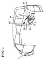
Fig. 1 is a perspective view of a vehicle in which an electrically operated device is installed according to an embodiment of the present invention; -
Fig. 2 is a plane view of the electrically operated device according to the embodiment of the present invention; -
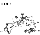
Fig. 3 is a perspective view showing an operation of the electrically operated device according to the embodiment of the present invention; -
Fig. 4 is a cross-sectional view of a feeding connector of the electrically operated device according to a first embodiment of the present invention; -
Fig. 5 is a plane view of a switch connector of the electrically operated device according to the first embodiment of the present invention; -
Fig. 6 is a cross-sectional view taken along the line A-A ofFig. 5 ; -
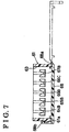
Fig. 7 is a cross-sectional view taken along the line B-B ofFig. 5 ; -
Fig. 8 is a cross sectional view of the feeding connector of the electrically operated device according to a second embodiment of the present invention; -
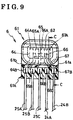
Fig. 9 is a plane view of the switch connector of the electrically operated device according to the second embodiment of the present invention; -
Fig. 10 is a cross-sectional view taken along the line C-C ofFig. 9 ; and -
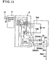
Fig. 11 is a circuit diagram showing a control means of the electrically operated device according to the embodiment of the present invention. - Embodiments of the present invention are explained with reference to the attached drawings.
- As shown in
Fig. 1 , a slidingdoor 12 for opening and closing anentrance 11A formed on a side body 11 is supported on avehicle 1, the slidingdoor 12 slidable in a vehicle longitudinal direction. The slidingdoor 12 accommodates therein both a door latch mechanism 2 for holding the slidingdoor 12 in a fully closed state or in a half-closed state, and adoor closure mechanism 3 for operating the door latch mechanism 2 in such a way that the slidingdoor 12 can be changed from a half-closed state to a fully closed state. - As shown in
Figs. 2 and3 , the door latch mechanism 2 and thedoor closure mechanism 3 are unitized by abracket 31 into a generally known structure. The door latch mechanism 2 includes both alatch 21, which, in a state where the striker and thelatch 21 are engaged with each other, is rotatably engageable and disengeagable with a striker (not shown) provided at an edge of theentrance 11A, and apawl 22, which is rotatably engageable and disengageable with thelatch 21. The slidingdoor 12 is either fully closed or half-closed, depending on an engaging position of thepawl 22 relative to thelatch 21 when thelatch 21 is in an engaging state with the striker. Thedoor closure mechanism 3 includes apassive lever 32 that can make contact with thelatch 21, and a drivengear 33 rotatably supported on thebracket 31 by means of apin 33a. The drivengear 33 rotatably supports thepassive lever 32 by means of apin 32a. In addition, the drivengear 33 meshes with anoutput pinion gear 42 of anactuator 4 whose drive source is anelectric motor 41. A driving force of theelectric motor 41 is transmitted to thepassive lever 32 via the drivengear 33. When theelectric motor 41 is driven, thepassive lever 32 is rotated so that thepassive lever 32 makes contact with thelatch 21 via the drivengear 33. As a result of the contact made by thepassive lever 32 with thelatch 21, thelatch 21 is then rotated so as to shift the slidingdoor 12 from a half-closed state to a fully closed state. - As shown in
Fig. 2 , anopen lever 23 is rotatably supported on thebracket 31 by means of apin 23a. One end of theopen lever 23 is connected to a door inside handle 13 (seeFig. 1 ), while the other end of theopen lever 23 is arranged in such a way that theopen lever 23 can make contact with thepawl 22. When the door insidehandle 13 is operated to rotate theopen lever 23, the other end of theopen lever 23 makes contact with thepawl 22 and thereby rotates thepawl 22. Then, the engagement between thepawl 22 and thelatch 21 is released, and thus the slidingdoor 12 can be shifted from a half-closed state, or from a fully closed state, to an open state. Theopen lever 23 is also connected to a door outside handle (not shown). - As shown in
Fig. 2 , theactuator 4 includes ahousing 43 accommodating a deceleration gear mechanism containing multiple gears therein. An input side of the deceleration gear mechanism is connected to theelectric motor 41 in such a way that power transmission is possible therebetween, while an output side of the deceleration gear mechanism is connected to theoutput pinion gear 42 in such a way that power transmission is possible therebetween. Thehousing 43 is fixed on thebracket 31 for supporting theelectric motor 41. In addition, apower feeding connector 5 is integrally formed on thehousing 43 for supplying the power to theelectric motor 41. - As shown in
Fig. 2 , anopen switch 24 is supported on thebracket 31 for detecting, as theopen switch 24 makes contact with theopen lever 23 in a rotational state, whether the door insidehandle 13 has been operated. In addition, alatch switch 25 is supported on thebracket 31 for detecting, as thelatch switch 25 makes contact with thelatch 21 in a rotational state, whether the slidingdoor 12 in a half-closed state, a fully closed state, or an open state. Theopen switch 24 includes twowire harnesses latch switch 25 includes threewire harnesses single switch connector 6 to thepower feeding connector 5 formed on theactuator 4. - The
switch connector 6 according to the first embodiment is explained below. - As shown in
Figs. 5 to 7 , theswitch connector 6 includes a synthetic-resin connectormain body 61. Anengaging convex portion 62 to be fit onto thepower feeding connector 5, and a cylindricalaccommodating portion 63 both of whose ends are opened, are formed on the connectormain body 61. Fouroutput terminals main body 61. One end of each of theoutput terminals convex portion 62, thus formingterminal connection portions output terminals accommodating portion 63, thus formingharness connection portions output terminal 66 is divided into two pieces and extends into the cylindricalaccommodating portion 63, thus formingharness connection portions slits 63a are formed on the cylindricalaccommodating portion 63, facing theharness connection portions open switch 24 are electrically connected to theharness connection portions respective slits 63a. The wire harnesses 25A, 25B, and 25C of thelatch switch 25 are electrically connected to theharness connection portions respective slits 63a. - A
cover member 68 having substantially an identical shape to that of the opening provided at a first end of the cylindricalaccommodating portion 63 is integrally formed on the connectormain body 61 by means of arotation hinge portion 68a. As shown inFig. 7 , an engagingprojection 68b formed on an opposite end of thecover member 68 to thehinge portion 68a engages with anengaging hook 61a formed on the connectormain body 61, thereby closing the opening provided at the first end of the cylindricalaccommodating portion 63. The inside of the cylindricalaccommodating portion 63 is insulated by means of a waterproof hot-melt process applied with the first end of the cylindricalaccommodating portion 63 in a closed state. Since, according to the employment, the cylindricalaccommodating portion 63 is closed by thecover member 68, in circumstances where theoutput terminals main body 61, the respective positions of theoutput terminals accommodating portion 63. In addition, thecover member 68 is integrally formed on the connectormain body 61 by means of therotation hinge portion 68a and by utilizing thecover member 68 any increases in the number of parts may be avoided. - Next, the
power feeding connector 5 according to the first embodiment is explained below. - As shown in
Fig. 4 , thepower feeding connector 5 includes a synthetic-resin connectormain body 51 having a cylindrical shape. A first engagingconcave portion 52 having an opening is formed on a first end of the connectormain body 51, while a second engagingconcave portion 53 having an opening is formed on the other, second, end of the connectormain body 51. Aconnector 71, for multiple wire harnesses 7 tied together, is positioned within the first engagingconcave portion 52 while theswitch connector 6 is positioned within the second engagingconcave portion 53. Twoinput terminals concave portion 52a of the first engagingconcave portion 52, are fixed by means of insert molding onto a portion provided as a bottom wall for both the engagingconcave portions main body 51. In addition, four through-holes 55 are formed on the bottom wall in parallel to theinput terminals concave portion 52a of the first engagingconcave portion 52 with a secondconcave portion 53a of the second engagingconcave portion 53. Theinput terminals electric motor 41. - The first
concave portion 52a of the first engagingconcave portion 52 faces a through-hole 12a formed on a doorinner panel 12A of the slidingdoor 12. The surroundings of the first engagingconcave portion 52 and the through-hole 12a are covered by an accordion-shapedseal member 56. - The engaging
convex portion 62 of theswitch connector 6 is positioned within the secondconcave portion 53a of the second engagingconcave portion 53 by means of aseal member 69. Theterminal connection portions output terminals switch connector 6 are inserted into the respective through-holes 55 of the connectormain body 51, and arranged within the firstconcave portion 52a of the first engagingconcave portion 52 in such a manner that theterminal connection portions terminal connection portions input terminals switch connector 6 with thepower feeding connector 5, anannular groove 69A, in the vicinity of which theseal member 69 is provided, is formed around the engagingconvex portion 62 of theswitch connector 6. Then, anannular flange 57, to be positioned within thegroove 69A, is formed to project around the secondconcave portion 53a of the second engagingconcave portion 53. The engaging strength between theswitch connector 6 and thepower feeding connector 5 is assured by the engagement between theflange 57 and thegroove 69A. - The
connector 71 for the wire harnesses 7 which have been tied together is led to the firstconcave portion 52a through the through-hole 12a and an inner side of theseal member 56, and then positioned at thepower feeding connector 5 within the engagingconcave portion 52. As a result, theinput terminals output terminals multiple connection terminals 72 of theconnector 71. An inner peripheral face of the firstconcave portion 52a functions as a guide face for theconnector 71, thereby assuring the accuracy of positional relationships between, on the one hand, theinput terminals output terminals connection terminals 72. - Next, the
switch connector 6 according to a second embodiment is explained below. - As shown in
Figs. 9 and10 , theswitch connector 6 includes a synthetic-resin connectormain body 61. An engagingconvex portion 62, to be fit onto apower feeding connector 5, is formed on the connectormain body 61. Fouroutput terminals main body 61. One end of each of theoutput terminals convex portion 62, thus formingterminal connection portions output terminals convex portion 62, thus formingharness connection portions output terminal 66 is divided into two pieces and extends outwards from the opposite end face of the engagingconvex portion 62 in the same way as theharness connection portions open switch 24 are electrically connected to theharness connection portions latch switch 25 are electrically connected to theharness connection portions harness connection portions cover member 61A which is integrally formed on the connectormain body 61 by resin-molding, and electrically insulated. In order to enhance mechanical strength between the connectormain body 61 and thecover member 61A, anengaging hook 61a formed on the connectormain body 61 and an engagingconcave portion 61b engage with each other. - The
power feeding connector 5 according to the second embodiment is explained as follows. - As shown in
Fig. 8 , thepower feeding connector 5 includes a synthetic-resin connectormain body 51 having a cylindrical shape. A first engagingconcave portion 52 having an opening is formed on a first end of the connectormain body 51, while a second engagingconcave portion 53 having an opening is formed on the other, second, end of the connectormain body 51. Aconnector 71, for multiple wire harnesses 7 tied together, is positioned within the first engagingconcave portion 52 while theswitch connector 6 is positioned within the second engagingconcave portion 53. Twoinput terminals concave portion 52a of the first engagingconcave portion 52, are fixed by means of insert molding onto a portion provided as a bottom wall for both the engagingconcave portions main body 51. In addition, a through-hole 58 is formed on the bottom wall, in parallel to theinput terminals concave portion 52a of the first engagingconcave portion 52 with the secondconcave portion 53a of the second engagingconcave portion 53. Theinput terminals electric motor 41. - The first
concave portion 52a of the first engagingconcave portion 52 faces a through-hole 12a formed on a doorinner panel 12A of the slidingdoor 12. The surroundings of the first engagingconcave portion 52 and the through-hole 12a are covered by an accordion-shapedseal member 56. - The engaging
convex portion 62 of theswitch connector 6 is positioned within the secondconcave portion 53a of the second engagingconcave portion 53 by means of aseal member 69. Theterminal connection portions output terminals switch connector 6, are inserted, together with the engagingconvex portion 62, into the through-hole 58 of the connectormain body 51 and arranged within the firstconcave portion 52a of the first engagingconcave portion 52 in such a manner that theterminal connection portions terminal connection portions input terminals flange arm 62A, including anengaging hole 62a, is formed to extend to an end tip of the engagingconvex portion 62. In addition, an engaginghook 52b, which can engage with the engaginghole 62a, is formed on an inner periphery of the firstconvex portion 52a. By virtue of the engagement between theengaging hole 62a and theengaging hook 52b, theswitch connector 6 is prevented from disengaging from thepower feeding connecter 5. - The
connector 71 for the wire harnesses 7 which have been tied is led to the firstconcave portion 52a through the through-hole 12a and an inner side of theseal member 56, and then positioned at thepower feeding connector 5 within the engagingconcave portion 52. As a result, theinput terminals output terminals multiple connection terminals 72 of theconnector 71. An inner peripheral face of the firstconcave portion 52a functions as a guide face for theconnector 71, thereby assuring the accuracy of the positional relationships between, on the one hand, theinput terminals output terminals connection terminals 72. - As shown in
Figs. 1 and11 , the tied wire harnesses 7 are electrically connected to an electronic control unit 8 provided on the inside of the slidingdoor 12. The electronic control unit 8 controls driving of theelectric motor 41 of theactuator 4 on the basis of signals received from theopen switch 24 and thelatch switch 25. In addition, the electronic control unit 8 is electrically connected to abattery 14 mounted on thevehicle 1 by means of a feedingcable 91, which is routed from the inside of the slidingdoor 12 to the side body 11 by means of aconstant feeding unit 9 provided within the slidingdoor 12. - According to the aforementioned embodiments, the wire harnesses 24A, 24B, 25A, 25B, and 25C of two types of switch, i.e. the
open switch 24 and thelatch switch 25, are combined together into theswitch connector 6. However, by increasing the number of output terminals, plural types of switch may be employed. In addition, because the output terminal can be grounded by means of the wire harnesses 7, a common earth terminal can be jointly used by theopen switch 24 and thelatch switch 25 by electrically connecting the wire harnesses 24A and 25C of theopen switch 24 and thelatch switch 25 respectively to acommon output terminal 66. Therefore, the number of output terminals of theswitch connector 6 may be drastically reduced, resulting in a decrease in costs. - An actuator for driving an operating mechanism that operates an operated member of a vehicle by means of a driving of an electric drive source and including a housing for supporting the electric drive source, and a power feeding connector formed on the housing and including an input terminal provided as an electric path to the electric drive source characterized in that the power feeding connector comprises a first engaging concave portion onto which a switch connector is fit, the switch connector including an output terminal provided as an electric path from a detecting means that detects an operation status of the operated member or the operating mechanism.
Claims (4)
- A vehicle-mounted electrically operated device comprising:an actuator (4) including an electric drive source (41) controlled by a control means (8) mounted on the vehicle (1) and receiving an electric power from a power source mounted on the vehicle;an operating mechanism (3) for operating an operated member (2) of the vehicle by means of a driving of the electric drive source; anda detecting means (24, 25) for detecting an operation status of the operated member or the operating mechanism and outputting a detection signal to the control means;characterized in thata first connector (6) including a first connection terminal (64, 65, 66, 67) for electrically connecting the detecting means to the control means, anda second connector (5) formed on the actuator and with which the first connector is engageable and disengageable, the second connector including a second connection terminal (54A, 54B) for electrically connecting the electric drive source to the control means, wherein the second connector includes a through-hole (55, 58) within which the first connection terminal is positioned.
- The vehicle-mounted electrically operated device according to claim 1, wherein the second connector includes a first engaging portion (53) onto which the first connector is fit, and a second engaging portion (52) provided to face the first engaging portion across the through-hole and onto which a third connector (71) is fit, the third connector including a third connection terminal (72) electrically connected to the first connection terminal and the second connection terminal.
- The vehicle-mounted electrically operated device according to claim 1, wherein the actuator includes a housing (43) for supporting the electric drive source and on which the second connector is integrally formed.
- The vehicle-mounted electrically operated device according to claim 2, wherein the actuator is accommodated in an opening and closing member (12) of the vehicle together with the operating mechanism and the operated member, and the second engaging portion faces an inner panel (12A) of the opening and closing member.
Applications Claiming Priority (2)
| Application Number | Priority Date | Filing Date | Title |
|---|---|---|---|
| JP2003406311A JP4453351B2 (en) | 2003-12-04 | 2003-12-04 | Actuator and in-vehicle electric actuator provided with the actuator |
| JP2003406311 | 2003-12-04 |
Publications (3)
| Publication Number | Publication Date |
|---|---|
| EP1538284A2 EP1538284A2 (en) | 2005-06-08 |
| EP1538284A3 EP1538284A3 (en) | 2008-08-27 |
| EP1538284B1 true EP1538284B1 (en) | 2019-10-30 |
Family
ID=34464004
Family Applications (1)
| Application Number | Title | Priority Date | Filing Date |
|---|---|---|---|
| EP04028624.7A Expired - Fee Related EP1538284B1 (en) | 2003-12-04 | 2004-12-02 | Vehicle-mounted electrically operated device |
Country Status (3)
| Country | Link |
|---|---|
| US (1) | US7461873B2 (en) |
| EP (1) | EP1538284B1 (en) |
| JP (1) | JP4453351B2 (en) |
Families Citing this family (19)
| Publication number | Priority date | Publication date | Assignee | Title |
|---|---|---|---|---|
| JP4394530B2 (en) * | 2004-07-22 | 2010-01-06 | アスモ株式会社 | Electric drive |
| JP4576321B2 (en) * | 2005-11-15 | 2010-11-04 | アスモ株式会社 | Actuator |
| JP4563315B2 (en) * | 2005-12-19 | 2010-10-13 | トヨタ車体株式会社 | Electrical component |
| JP4734212B2 (en) * | 2006-10-17 | 2011-07-27 | 三井金属アクト株式会社 | Latch device |
| JP4795195B2 (en) * | 2006-10-17 | 2011-10-19 | 三井金属アクト株式会社 | Latch device |
| US8196975B2 (en) * | 2007-08-14 | 2012-06-12 | Magna Closures Inc | Safety device for vehicle door latch systems |
| US8967682B2 (en) * | 2007-08-14 | 2015-03-03 | Magna Closures Inc. | Vehicle door latch with motion restriction device prohibiting rapid movement of opening lever |
| DE202008003886U1 (en) * | 2008-03-20 | 2008-07-24 | Kiekert Ag | Device for realizing a dry electrical connection of a motor vehicle lock |
| CN102470780B (en) | 2009-07-15 | 2015-04-08 | 约翰逊控股公司 | Mechatronic unlocking means |
| JP4802347B2 (en) * | 2009-07-16 | 2011-10-26 | 三井金属アクト株式会社 | Control device for vehicle door latch |
| JP5685853B2 (en) * | 2010-08-19 | 2015-03-18 | 株式会社アンセイ | Vehicle door opening and closing device |
| JP5978484B2 (en) * | 2011-08-31 | 2016-08-24 | 三井金属アクト株式会社 | Vehicle door latch device |
| JP5729322B2 (en) * | 2012-02-08 | 2015-06-03 | トヨタ自動車株式会社 | Vehicle side structure |
| CN104662243B (en) * | 2012-09-26 | 2017-09-12 | 爱信精机株式会社 | Vehicle remote control |
| DE112014004455T5 (en) * | 2013-09-25 | 2016-06-23 | Magna Closures S.P.A. | Electric vehicle lock |
| EP3257693B1 (en) * | 2015-02-12 | 2021-06-30 | Gecom Corporation | Door latch device |
| US10454334B2 (en) * | 2016-04-22 | 2019-10-22 | Hanon Systems | Compressor |
| JP6927118B2 (en) * | 2018-03-29 | 2021-08-25 | 株式会社豊田自動織機 | In-vehicle electric compressor |
| FR3081179B1 (en) * | 2018-05-18 | 2020-07-10 | U-Shin Italia S.P.A. | AUTOMOTIVE DOOR HANDLE DEVICE WITH OPTIMIZED CONNECTIONS |
Citations (1)
| Publication number | Priority date | Publication date | Assignee | Title |
|---|---|---|---|---|
| US5360351A (en) * | 1990-04-04 | 1994-11-01 | Rockwell International Corporation | Housing for the interface between a motor vehicle lock, its actuator and the electrical connection harness of the vehicle |
Family Cites Families (16)
| Publication number | Priority date | Publication date | Assignee | Title |
|---|---|---|---|---|
| JPS62101782A (en) * | 1985-10-30 | 1987-05-12 | 株式会社 大井製作所 | Door lock control apparatus for car |
| IT216961Z2 (en) * | 1989-03-07 | 1991-10-21 | Roltra Spa | ELECTRIC LOCK ACTUATOR DEVICE |
| JP3324223B2 (en) * | 1993-06-04 | 2002-09-17 | アイシン精機株式会社 | Door lock device |
| JP3069488B2 (en) * | 1994-02-26 | 2000-07-24 | 三井金属鉱業株式会社 | Actuator unit for vehicle door lock device |
| JP2948491B2 (en) * | 1994-11-21 | 1999-09-13 | 三井金属鉱業株式会社 | Actuator for vehicle locking device |
| DE19702205B4 (en) * | 1997-01-23 | 2004-12-23 | Kiekert Ag | Motor vehicle door lock, in particular for motor vehicles with a central locking and anti-theft device |
| DE19845723B4 (en) | 1997-10-06 | 2006-10-26 | Mitsui Kinzoku Kogyo K.K. | Locking device for a vehicle door |
| FR2776857B1 (en) * | 1998-03-26 | 2000-06-16 | Meritor Light Vehicle Sys Ltd | ELECTRIC MOTOR FOR ACTIVATION OF A FUNCTIONAL MEMBER OF A MOTOR VEHICLE |
| US6131337A (en) * | 1998-04-22 | 2000-10-17 | Aisin Seiki Kabushiki Kaisha | Vehicle door closing apparatus |
| DE19828040B4 (en) * | 1998-06-24 | 2005-05-19 | Siemens Ag | Power assisted closing device |
| DE19843422C5 (en) * | 1998-09-22 | 2008-03-06 | Bayerische Motoren Werke Ag | Door lock of a motor vehicle |
| DE10100010B4 (en) * | 2001-01-02 | 2005-05-12 | Brose Schließsysteme GmbH & Co.KG | Motor vehicle door lock, designed as an electric lock, and method for assembling a motor vehicle door lock designed as an electric lock |
| US6557911B2 (en) * | 2001-01-23 | 2003-05-06 | Kiekert Ag | Power-open motor-vehicle door latch |
| US6637783B2 (en) * | 2001-05-14 | 2003-10-28 | Ohi Seisakusho Co., Ltd. | Opening and closing device of vehicle lock apparatus |
| US7038337B2 (en) * | 2003-05-20 | 2006-05-02 | Siemens Vdo Automotive Corporation | EMI suppression in permanent magnet DC motors having PCB outside motor in connector and overmolded |
| US6927514B2 (en) * | 2003-08-18 | 2005-08-09 | C-Mac Invotronics | Integrated actuator |
-
2003
- 2003-12-04 JP JP2003406311A patent/JP4453351B2/en not_active Expired - Fee Related
-
2004
- 2004-12-01 US US11/000,391 patent/US7461873B2/en active Active
- 2004-12-02 EP EP04028624.7A patent/EP1538284B1/en not_active Expired - Fee Related
Patent Citations (1)
| Publication number | Priority date | Publication date | Assignee | Title |
|---|---|---|---|---|
| US5360351A (en) * | 1990-04-04 | 1994-11-01 | Rockwell International Corporation | Housing for the interface between a motor vehicle lock, its actuator and the electrical connection harness of the vehicle |
Also Published As
| Publication number | Publication date |
|---|---|
| JP2005163456A (en) | 2005-06-23 |
| US7461873B2 (en) | 2008-12-09 |
| US20050121920A1 (en) | 2005-06-09 |
| JP4453351B2 (en) | 2010-04-21 |
| EP1538284A3 (en) | 2008-08-27 |
| EP1538284A2 (en) | 2005-06-08 |
Similar Documents
| Publication | Publication Date | Title |
|---|---|---|
| EP1538284B1 (en) | Vehicle-mounted electrically operated device | |
| US7703310B2 (en) | Door opening and closing device for vehicle and assembly method thereof | |
| EP1436479B1 (en) | Modular lock for a door of a motor vehicle and door provided with this lock | |
| US7232161B2 (en) | Latch device for vehicle tailgate | |
| US20040262927A1 (en) | Door lock device | |
| US20030111863A1 (en) | Motor vehicle door locking system | |
| KR20020041287A (en) | Door lock drive unit | |
| GB2216171A (en) | Electrical switch for door latch assembly | |
| US6552659B1 (en) | Device for transmitting mechanical control movements and/or electric signals between a door actuating device and a door closer device of a motor vehicle door | |
| US10407947B2 (en) | Vehicle door lock device | |
| JP2004353328A (en) | Door lock device and door lock module | |
| JP2001128407A (en) | Motor unit of power window apparatus | |
| JP3864504B2 (en) | Sunroof drive | |
| JP3783252B2 (en) | Door lock drive device | |
| CN107871630B (en) | Vehicle push-button switch device | |
| JP2001311339A (en) | Door lock operating device | |
| JP4110901B2 (en) | Door opening / closing operation device | |
| CN112727269A (en) | Door latch device | |
| JP4327677B2 (en) | Door latch device for automobile | |
| JP3750162B2 (en) | Waterproof device for drive mechanism | |
| EP1691011A1 (en) | Door open-close device | |
| JPH10159412A (en) | Door lock driving device | |
| CN112727268B (en) | Latch device | |
| CN218881901U (en) | Door latch lock device | |
| CN216893899U (en) | Water-proof structure of door lock device |
Legal Events
| Date | Code | Title | Description |
|---|---|---|---|
| PUAI | Public reference made under article 153(3) epc to a published international application that has entered the european phase |
Free format text: ORIGINAL CODE: 0009012 |
|
| AK | Designated contracting states |
Kind code of ref document: A2 Designated state(s): AT BE BG CH CY CZ DE DK EE ES FI FR GB GR HU IE IS IT LI LT LU MC NL PL PT RO SE SI SK TR |
|
| AX | Request for extension of the european patent |
Extension state: AL BA HR LV MK YU |
|
| PUAL | Search report despatched |
Free format text: ORIGINAL CODE: 0009013 |
|
| AK | Designated contracting states |
Kind code of ref document: A3 Designated state(s): AT BE BG CH CY CZ DE DK EE ES FI FR GB GR HU IE IS IT LI LT LU MC NL PL PT RO SE SI SK TR |
|
| AX | Request for extension of the european patent |
Extension state: AL BA HR LV MK YU |
|
| 17P | Request for examination filed |
Effective date: 20080908 |
|
| AKX | Designation fees paid |
Designated state(s): DE FR GB TR |
|
| 17Q | First examination report despatched |
Effective date: 20101227 |
|
| STAA | Information on the status of an ep patent application or granted ep patent |
Free format text: STATUS: EXAMINATION IS IN PROGRESS |
|
| REG | Reference to a national code |
Ref country code: DE Ref legal event code: R079 Ref document number: 602004054328 Country of ref document: DE Free format text: PREVIOUS MAIN CLASS: E05B0017220000 Ipc: E05B0081200000 |
|
| RIC1 | Information provided on ipc code assigned before grant |
Ipc: E05B 81/54 20140101ALI20190329BHEP Ipc: E05B 83/40 20140101ALI20190329BHEP Ipc: E05B 81/20 20140101AFI20190329BHEP Ipc: E05F 15/60 20150101ALI20190329BHEP Ipc: E05B 81/64 20140101ALI20190329BHEP |
|
| GRAP | Despatch of communication of intention to grant a patent |
Free format text: ORIGINAL CODE: EPIDOSNIGR1 |
|
| STAA | Information on the status of an ep patent application or granted ep patent |
Free format text: STATUS: GRANT OF PATENT IS INTENDED |
|
| INTG | Intention to grant announced |
Effective date: 20190514 |
|
| GRAS | Grant fee paid |
Free format text: ORIGINAL CODE: EPIDOSNIGR3 |
|
| GRAA | (expected) grant |
Free format text: ORIGINAL CODE: 0009210 |
|
| STAA | Information on the status of an ep patent application or granted ep patent |
Free format text: STATUS: THE PATENT HAS BEEN GRANTED |
|
| AK | Designated contracting states |
Kind code of ref document: B1 Designated state(s): DE FR GB TR |
|
| REG | Reference to a national code |
Ref country code: GB Ref legal event code: FG4D |
|
| REG | Reference to a national code |
Ref country code: DE Ref legal event code: R096 Ref document number: 602004054328 Country of ref document: DE |
|
| PGFP | Annual fee paid to national office [announced via postgrant information from national office to epo] |
Ref country code: DE Payment date: 20191119 Year of fee payment: 16 |
|
| REG | Reference to a national code |
Ref country code: DE Ref legal event code: R097 Ref document number: 602004054328 Country of ref document: DE |
|
| PLBE | No opposition filed within time limit |
Free format text: ORIGINAL CODE: 0009261 |
|
| STAA | Information on the status of an ep patent application or granted ep patent |
Free format text: STATUS: NO OPPOSITION FILED WITHIN TIME LIMIT |
|
| GBPC | Gb: european patent ceased through non-payment of renewal fee |
Effective date: 20200130 |
|
| 26N | No opposition filed |
Effective date: 20200731 |
|
| PG25 | Lapsed in a contracting state [announced via postgrant information from national office to epo] |
Ref country code: FR Free format text: LAPSE BECAUSE OF NON-PAYMENT OF DUE FEES Effective date: 20191230 Ref country code: GB Free format text: LAPSE BECAUSE OF NON-PAYMENT OF DUE FEES Effective date: 20200130 |
|
| REG | Reference to a national code |
Ref country code: DE Ref legal event code: R119 Ref document number: 602004054328 Country of ref document: DE |
|
| PG25 | Lapsed in a contracting state [announced via postgrant information from national office to epo] |
Ref country code: DE Free format text: LAPSE BECAUSE OF NON-PAYMENT OF DUE FEES Effective date: 20210701 |
|
| PG25 | Lapsed in a contracting state [announced via postgrant information from national office to epo] |
Ref country code: TR Free format text: LAPSE BECAUSE OF FAILURE TO SUBMIT A TRANSLATION OF THE DESCRIPTION OR TO PAY THE FEE WITHIN THE PRESCRIBED TIME-LIMIT Effective date: 20191030 |