EP1538028A2 - Electronic equipment tilting and rotating apparatus - Google Patents
Electronic equipment tilting and rotating apparatus Download PDFInfo
- Publication number
- EP1538028A2 EP1538028A2 EP04257364A EP04257364A EP1538028A2 EP 1538028 A2 EP1538028 A2 EP 1538028A2 EP 04257364 A EP04257364 A EP 04257364A EP 04257364 A EP04257364 A EP 04257364A EP 1538028 A2 EP1538028 A2 EP 1538028A2
- Authority
- EP
- European Patent Office
- Prior art keywords
- rotated
- display unit
- spring
- electronic equipment
- display panel
- Prior art date
- Legal status (The legal status is an assumption and is not a legal conclusion. Google has not performed a legal analysis and makes no representation as to the accuracy of the status listed.)
- Withdrawn
Links
Images


Classifications
-
- B—PERFORMING OPERATIONS; TRANSPORTING
- B60—VEHICLES IN GENERAL
- B60R—VEHICLES, VEHICLE FITTINGS, OR VEHICLE PARTS, NOT OTHERWISE PROVIDED FOR
- B60R11/00—Arrangements for holding or mounting articles, not otherwise provided for
- B60R11/02—Arrangements for holding or mounting articles, not otherwise provided for for radio sets, television sets, telephones, or the like; Arrangement of controls thereof
- B60R11/0229—Arrangements for holding or mounting articles, not otherwise provided for for radio sets, television sets, telephones, or the like; Arrangement of controls thereof for displays, e.g. cathodic tubes
- B60R11/0235—Arrangements for holding or mounting articles, not otherwise provided for for radio sets, television sets, telephones, or the like; Arrangement of controls thereof for displays, e.g. cathodic tubes of flat type, e.g. LCD
-
- B—PERFORMING OPERATIONS; TRANSPORTING
- B60—VEHICLES IN GENERAL
- B60R—VEHICLES, VEHICLE FITTINGS, OR VEHICLE PARTS, NOT OTHERWISE PROVIDED FOR
- B60R11/00—Arrangements for holding or mounting articles, not otherwise provided for
- B60R2011/0042—Arrangements for holding or mounting articles, not otherwise provided for characterised by mounting means
- B60R2011/008—Adjustable or movable supports
- B60R2011/0085—Adjustable or movable supports with adjustment by rotation in their operational position
-
- B—PERFORMING OPERATIONS; TRANSPORTING
- B60—VEHICLES IN GENERAL
- B60R—VEHICLES, VEHICLE FITTINGS, OR VEHICLE PARTS, NOT OTHERWISE PROVIDED FOR
- B60R11/00—Arrangements for holding or mounting articles, not otherwise provided for
- B60R2011/0042—Arrangements for holding or mounting articles, not otherwise provided for characterised by mounting means
- B60R2011/008—Adjustable or movable supports
- B60R2011/0092—Adjustable or movable supports with motorization
-
- Y—GENERAL TAGGING OF NEW TECHNOLOGICAL DEVELOPMENTS; GENERAL TAGGING OF CROSS-SECTIONAL TECHNOLOGIES SPANNING OVER SEVERAL SECTIONS OF THE IPC; TECHNICAL SUBJECTS COVERED BY FORMER USPC CROSS-REFERENCE ART COLLECTIONS [XRACs] AND DIGESTS
- Y10—TECHNICAL SUBJECTS COVERED BY FORMER USPC
- Y10S—TECHNICAL SUBJECTS COVERED BY FORMER USPC CROSS-REFERENCE ART COLLECTIONS [XRACs] AND DIGESTS
- Y10S248/00—Supports
- Y10S248/917—Video display screen support
- Y10S248/919—Adjustably orientable video screen support
Definitions
- the present invention relates to an electronic equipment tilting and rotating apparatus, and particularly to a tilting and rotating apparatus for use with a display panel rotating mechanism of a built-in type display apparatus, such as a vehicle television receiver and a car navigation system.
- vehicle electronic equipment such as a vehicle television receiver and a car navigation system
- vehicle electronic equipment such as a vehicle television receiver and a car navigation system
- a display apparatus such as a liquid-crystal monitor
- the display apparatus is housed within a compartment portion of a main body of the vehicle electronic equipment.
- the display apparatus is moved (slid and tilted) to the ejected position of the front of the main body and it becomes available for practical use.
- FIG. 1 of the accompanying drawings shows an example of such vehicle electronic equipment. More specifically, FIG. 1 is an outward appearance perspective view showing the state in which a display panel 91 is moved to the front of a main body 92 of the vehicle electronic equipment and is thereby placed at the ejected position. As schematically shown in FIG. 1, this vehicle electronic equipment comprises the display panel 91, the main body 92 and an arm 93.
- the display panel 91 is rotatably supported to the main body 92 through the arm 93.
- the display panel 91 has a suitable means such as a tilt gear disposed at its back surface.
- This tilt gear is meshed with a transmission gear (that is, part of a mechanical assembly which will be described later on) disposed within the main body 92. Then, the tilt gear is rotated as the transmission gear is rotated, whereby the display panel 91 is rotated around a support shaft 94 of the arm 93.
- the main body 92 of this vehicle electronic equipment comprises a compartment portion for housing therein the display panel 91 or the like and a control circuit for energizing and controlling the display panel 91.
- the main body 92 is held on the vehicle electronic equipment such that the mechanical assembly including the arm 93 can be slid freely.
- this mechanical assembly is composed of a sliding and moving mechanism and a tilting and rotating mechanism in addition to the arm 93.
- the sliding and moving mechanism is composed of a slide motor and a coaxial gear for sliding the mechanical assembly within the main body 92.
- the tilting and rotating mechanism is composed of a tilt motor and a transmission gear by which the display panel 91 is tilted and rotated.
- the arm 93 moves the display panel 91 while holding the display panel 91 in substantially the horizontal direction. Also, when the display panel 91 is tilted and rotated, the arm 93 properly holds the display panel 91 which can be rotate around the support shaft 94.
- FIGS. 2A to 2D are schematic diagrams to which reference will be made in explaining the manner in which the display panel 91 is slid from the housing position within the main body 92 to the ejected position of the front of the main body 92 so that the display panel 91 may rise from the horizontal state. It is customary that such vehicle electronic equipment is housed within the instrument panel of the car.
- the tilting and rotating mechanism of the mechanical assembly starts driving the display panel 91.
- rotation driving force is transmitted to the tilt gear of the display panel 91 so that the display panel 91 is rotated (tilted up) so as to rise in the direction shown by an arrow 110A in FIG. 2C.
- the display panel 91 is continued to be tilted and rotated with application of the driving force of the tilting and rotating mechanism and as shown in FIG. 2D, the display panel 91 is tilted up to the available position at which it becomes perpendicular to the arm 93 and at which it becomes available for use, for example.
- the tilting and rotating mechanism stops driving the display panel 91.
- the display panel 91 when a user uses the display panel 91 housed within the main body 92, the display panel 91 can automatically be slid and moved up to the ejected position of the front of the main body 92 so that it can be tilted and rotated up to the available position at which the display panel 91 becomes available for use.
- moment of rotation may be obtained by multiplying a distance (moment's arm) between an action line passing the center of gravity of the display panel 91 and which is generated by the weight of the display panel 91 and the center of the rotary shaft 94 with the weight of the display panel 91. Therefore, the length of the moment's arm is changed with the rotation of the display panel 91.
- moment of rotation becomes the maximum.
- the moment of rotation becomes zero. Accordingly, when the display panel 91 is placed in substantially the horizontal direction, the moment of rotation becomes the maximum value.
- the driving torque necessary for rotating the display panel 91 against the moment of rotation generated by the weight of the display panel 91 is increased and hence a motor having a large driving torque becomes necessary.
- the display panel 91 is tilted and rotated in the state in which the display panel 91 rises to a certain extent, the length of the moment's arm is reduced and hence a driving torque that is not so large is not required. Therefore, when the vehicle electronic equipment is in practical use, it is sufficient that the display panel 91 may be driven with application of a very small driving torque by which "backlash" (play) of a gear and backlash of a driving gear against vibrations of a vehicle can be removed and by which moment of one direction generated around the rotary shaft can be applied to the display panel.
- an object of the present invention to provide an electronic equipment tilting and rotating apparatus which can tilt and rotate electronic equipment mounted thereon by a necessary and minimum driving torque.
- an electronic equipment tilting and rotating apparatus having a rotated member joined by a rotating mechanism mounted on a frame, the rotated member tilted and rotated against gravity by the rotating mechanism of the frame so that the rotated member can be used.
- This electronic equipment tilting and rotating apparatus is comprised of a first elastic member for spring-biasing the rotated member around a rotary shaft of the rotated member so that the rotated member rises from the horizontal direction and a second elastic member for spring-biasing the rotated member during the rotated member is being rotated from the anti-rising direction to the rising direction in which the second elastic member makes a driving torque become substantially constant against the weight of the rotated member.
- the electronic equipment tilting and rotating apparatus of the present invention can decrease a starting torque required to start rotating the rotated member to rise from substantially the horizontal state. Also, a driving torque in the rotation process becomes substantially constant and a motor of which torque capacity is necessary and minimum can be used, power consumption of the motor being decreased. Further, this electronic equipment tilting and rotating apparatus can be miniaturized in size and it can save its space within a mechanical assembly.
- the second elastic member has one end engaged with the frame and it has also the other end engaged with an engagement pin disposed at the position displaced from the center of the rotary shaft of the rotated member, the second elastic member being disposed such that its length becomes longest during the rotated member is being tilted and rotated.
- the first elastic member is a torsion coil spring and the second elastic member is an extension spring.
- the frame with the rotated member joined thereto includes a sliding and moving means.
- the rotated member and all units mounted on the frame are generally housed within the electronic equipment. According to the need, the frame with the rotated member jointed thereto can be slid and protruded, whereafter the rotated member can be tilted and rotated from the frame and it may become available for use.
- a motor for use with the tilting and rotating apparatus may have a necessary and minimum driving torque and hence, this tilting and rotating apparatus can consume small electric power and can save a space.
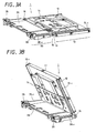
- FIGS. 3A and 3B show a slide unit 1 having a display panel such as a liquid-crystal display device mounted thereon for use with a car navigation system that is an example of the vehicle electronic equipment shown in FIG. 1.
- a display panel such as a liquid-crystal display device mounted thereon for use with a car navigation system that is an example of the vehicle electronic equipment shown in FIG. 1.
- FIG. 3A is a perspective view showing the state in which the slide unit 1 is placed in substantially the horizontal direction after the display panel of the slide unit 1 was slid and moved in the lateral direction from an electronic equipment compartment such as an instrument panel or a console panel of the car.
- FIG. 3B is a rear perspective view showing the state in which the slide unit 1 becomes available for use after the display panel rose from the horizontal state since the display panel has been slid and moved in the lateral direction from the electronic equipment compartment.
- the slide unit 1 comprises a display unit 10 and a mechanical assembly 20.
- the display unit 10 and the mechanical assembly 20 are joined by rotary shafts 15, 16 which are provided coaxially.
- the display unit 10 is composed of a fixed plate 12 with a display panel 11 and the like fixed thereto and a rotary plate 14 with this fixed plate 12 fixed thereto.
- the display panel 11 is a liquid-crystal display device to display proper information such as road map information and facilities/sightseeing information in color.
- the fixed plate 12 is decreased in weight by partly thinning substantially square-like aluminum or aluminum alloy and other light-metal plate material while its strength is being maintained. Then, the fixed plate 12 has slide grooves 12-1, 12-1 formed at their respective sides to guide the display panel 11 so that the display panel 11 and an equipment main body fixed to the car instrument panel can be slid forwards and backwards smoothly.
- the rotary plate 14 is a substantially rectangular-shaped plate treated by an embossing process or whose peripheral edge is treated by a folding process in order to increase its strength. Then, the rotary plate 14 has a plurality of holes to connect electric wires from the display unit 10 to terminals provided in the inside of the equipment main body. These holes of the rotary plate 14 are also used to decrease the weight of the rotary plate 14. Insertion apertures for receiving the rotary shafts 15, 16 are formed on the two folded portions of the short sides of the plate, respectively. Then, a partial gear assembly 13 is provided near the right-hand side rotary shaft 15 shown in FIG. 4 in such a manner that a rotation center 13a of a partial gear of the partial gear assembly 13 may substantially coincide with the centers of the rotary shafts 15, 16.
- the partial gear assembly 13 has a tooth form of a spur gear formed on its substantially half circumference and it has also an attachment bracket of the rotary plate 14 formed on the area in which the tooth form of the circumference is not formed. Then, an engagement pin 17 with which one end of a spring engages is formed at the position displaced from the rotation center 13a of this partial gear.
- a mechanical assembly 20 is composed of a mechanical plate 26, a sliding and moving mechanism 21 mounted on the mechanical plate 26 to slide the slide unit 1 itself and a tilting and rotating mechanism 30 for tilting and rotating the display unit 10, etc.
- the mechanical plate 26 is a substantially rectangular-like plate treated by an embossing process or of which peripheral edge is folded in order to increase its strength.
- the mechanical plate 26 has a plurality of holes to connect electric wires to terminals provided in the inside of the equipment main body in order to control supply of power to the sliding and moving mechanism 21 and the tilting and rotating mechanism 30. These holes on the mechanical plate 26 may contribute to decrease of the weight of the plate.
- the mechanical plate 26 has insertion apertures formed at respective end portions of the two folded portions thereof to receive the rotary shafts 15, 16 and it has also a pin 27 formed thereon to fix one end of the spring thereto.
- slide guides 28, 29 having notches 28-1, 29-1 are formed on the side surfaces of the two sides of the folded portions of the short sides of the plate.
- the sliding and moving mechanism 21 decelerates rotation force of a motor 22 through a worm gear (not shown) and a spur gear (not shown) to increase a driving torque and transmits the rotation force of the motor 22 to a worm 24 provided on a slide drive shaft 23 to drive slide drive pinions 25, 25 provided at both ends of this slide drive shaft 23.
- the former is meshed with the slide drive pinions 25, 25 and the latter is engaged with the slide guide notches 28-1, 29-1 of the mechanical plate 26 and the slide grooves 12-1, 12-1 of the fixed plate 12.
- the slide unit 1 can be moved forwards and backwards to the equipment main body housing position and the ejected position of the front by the sliding and moving mechanism 21 of the slide unit 1.
- the tilting and rotating mechanism 30 transmits the rotation force of the motor 22 to a reduction gear train 33 by means of a bevel gear 31. Then, a gear provided at the last stage decelerate the rotation force of the motor 22 up to a reduction gear ratio of approximately 1/100 to thereby amplify the driving torque to tilt and rotate the slide unit 1.
- the mechanical plate 26 and the rotary plate 14 are constructed as described above and the mechanical plate 26 and the rotary plate 14 are joined so as to become freely rotatable by inserting the rotary shafts 15, 16 into rotary shaft apertures thereof.
- the rotary shaft 15 shown in FIG. 4 is elongated such that its shaft may protrude inwardly to serve as a shaft.
- the partial gear assembly 13 of the rotary plate 14 is meshed with the gear 34 of the last stage of the reduction gear train 33 of the mechanical plate 26 and is thereby assembled into the slide unit 1 so as to be rotated freely by the rotary shafts 15, 16.
- a torsion coil spring 38 made of a steel wire serving as a first elastic member is provided on the shaft of the thus elongated rotary shaft 15 and it is assembled into the slide unit 1 in such a manner that its respective ends may be engaged with the rotary plate 14 and the mechanical plate 26. At that time, the torsion coil spring 38 is spring-biased in the direction such that the display panel 11 may rise from the horizontal state as shown in FIG. 3B.
- the torsion coil spring 38 is assembled into the slide unit 1 such that the rotary plate 14 and the mechanical plate 26 may be rotated in the direction shown by an arrow (A) or (B) in FIG. 4 under spring force of the torsion coil spring 38.
- an extension spring 39 made of a steel wire serving as a second elastic member is extended between the erected pin 27 formed on the mechanical plate 26 and the engagement pin 17 erected on the partial gear assembly 13 secured to the rotary plate 14.
- FIGS. 5A to 5C The manner in which the spring-biasing force of the extension spring 39 is changed with the rotation of the rotary plate 14 will be described with reference to FIGS. 5A to 5C.
- the direction in which the display panel 11 rises from the horizontal state is set to the counter-clockwise direction relative to the rotation center 13a of the partial gear assembly 13.
- extension spring 39 is engaged with the engagement pin 17 formed on the partial gear assembly 13 and the other end thereof is engaged with the erected pin 27. Then, when the display panel 11 is tilted and rotated so that it may rise from the horizontal state, the rotary plate 14 with the partial gear assembly 13 secured thereto is rotated from the substantially horizontal state shown in FIG. 5A to the rotation end point shown in FIG. 5C via the intermediate position shown in FIG. 5B.
- the engagement pin 17 is formed on the partial gear assembly 13 in such a manner that a distance between the center of the engagement pin 17 and the center of the erected pin 27 may be minimized (length L2 ) in the state shown in FIG. 5B. More specifically, the engagement pin 17 is formed on the partial gear assembly 13 in such a manner that the center of the extension spring 39 may pass the rotation center 13a of the partial gear assembly 13 while the rotary plate 14 is being rotated as shown in FIG. 5B and that the distance between the center of the engagement pin 17 and the center of the erected pin 27 becomes longer than the length L2 in the horizontal state in which the display unit 10 is slid and moved in the horizontal direction as shown in FIG. 5A (length L1 ) and in the state in which the display unit 10 is tilted and rotated so as rise from the horizontal state as shown in FIG. 5C (length L3 ).
- a spring-biasing force of the clockwise direction is generated in the state in which the display unit 10 is placed in substantially the horizontal state as shown in FIG. 5A and a spring-biasing force of the counter-clockwise direction is generated in the state in which the display unit 10 is tilted and rotated so as to rise from the horizontal state as shown in FIG. 5C.
- the display unit 10 is given constant spring-biasing force by the motor 32 such that the rotary plate 14 of the display unit 10 may be placed in substantially the horizontal state against the resultant force of moments.
- the rotary plate 14 is tilted and rotated by the motor 32 until the display unit 10 rises from the horizontal state as shown in FIG. 3B.
- FIG. 8 is a schematic diagram showing the manner in which the display unit 10 is tilted and rotated so as to rise from substantially the horizontal state relative to the rotary shaft 14 wherein ⁇ represents an angle formed between the rotary plate 14 and the mechanical plate 26 comprising the display unit 10.
- a downward arrow 8R in FIG. 8 shows the gravity direction of center of gravity at substantially the center of the display unit 10 and reference letter L represents an arm's length of moment generated by gravity.
- FIG. 9 is a diagram showing characteristic curves obtained when the results of moments generated at an interval of 5°relative to the rotation angle ⁇ between the rotary plate 14 and the mechanical plate 26 were plotted in which the horizontal axis represents the rotation angle ⁇ and the vertical axis represents the generated moments (relative values).
- the rotation angle ⁇ is obtained in the state in which the clockwise direction is assumed to be the positive direction and in which the counter-clockwise direction is assumed to be the negative direction.
- the center of gravity which exists at substantially the center, also is rotated.
- the arm's length L of the moment generated by the weight of the display unit 10 is changed.
- the moment generated by the torsion coil spring 38 is obtained by multiplying spring force proportional to the rotation angle with a distance (length of arm of moment) from the center of the torsion coil spring 38 to the engagement position of each plate of both ends of the spring.
- the torsion coil spring 38 which is spring-biased around the center axis of the coil, has elastic modulus substantially proportional to the rotation angle of the torsion and spring-biases the display unit 10 in the positive direction in which the display unit 10 can rise from the horizontal direction.
- the moment of the torsion coil spring 38 reaches the maximum value 49.
- the moment of the torsion coil spring 38 reaches the value 15.
- the moment of the torsion coil spring 38 reaches the minimum value 6.
- the moment generated by the extension spring 39 is calculated by multiplying spring force proportional to the extension of the extension spring 39 with eccentricity e obtained between the rotation center 13a of the partial gear assembly 13 and the extension action line as shown in FIGS. 5A and 5C.
- the extension spring 39 used herein is an ordinary extension spring having an elastic modulus proportional to the extension of the spring.
- the engagement pin 17 is rotated at the rotation center 13a of the partial gear assembly 13. As this engagement pin 17 is rotated, one end of the extension spring 39 engaged with the engagement pin 17 is rotated as shown in FIGS. 5A to 5C.
- the moment of the extension spring 39 reaches the minimum value -2.
- the moment of the extension spring 39 reaches 0.
- the moment of the extension spring 39 reaches the maximum value 10.
- the moment of the extension spring 39 reaches a value 8.
- the value of the moment of the resultant force lies in a range of from 22 to 27 and hence a substantially constant spring-biasing force can be obtained.
- the spring engagement is provided at the proper position and amount of force is adjusted by properly adjusting spring characteristics of respective springs, whereby substantially constant moment can be obtained.
- Motor driving force is transmitted to the gear 34 of the final stage of the reduction gear train 33 against the moment of the resultant force which is the substantially constant spring-biasing force to rotate the partial gear assembly 13 meshed with the gear 34, whereby the display unit 10 is tilted and rotated.
- the reduction gear ratio from the worm 24 fixed to the rotary drive shaft of the motor 32 to the gear 34 of the final stage of the reduction gear train 33 is as large as substantially 1/100, when the tilting and rotating operation of the display unit 10 is stopped at a predetermined angle and the stopped state of the display unit 10 is maintained, holding power of the motor 32 against the spring-biasing force of the above-mentioned combined spring is small and a power consumption of the motor 32 also can be decreased.
- a spring-biasing force of one direction around the rotary shafts 15, 16, required when the display unit 10 is placed in substantially the horizontal position or when the display unit 10 rises, and which is required to remove "backlash" of the display unit 10 against vibrations of the vehicle and backlash of the driving gear and the substantially constant moment regardless of the rotation angle can be applied to the tilting and rotating apparatus by the motor 32. Therefore, fluctuation of the driving torque of the motor 32 is small so that the motor 32 having the necessary and minimum driving torque can be selectively used.
- the tilting and rotating apparatus can decrease its power consumption and it can also save its space.
- the rotary plate 14 and the mechanical plate 26 can drive the motor 32 by a substantially constant tilting and rotating torque in the process in which the rotary plate 14 with the display unit 10 fixed thereto is rotated from substantially the horizontal state to the rising state. Also, since it is sufficient that a driving torque required by the motor 32 should be a necessary and minimum driving torque, the motor 32 can be miniaturized and decreased in power consumption.
- the present invention is not limited thereto and elastic members made of various materials can be used. That is, elastic members made of other materials than the steel wire can be used and a resin itself having high elasticity need not be formed like a coil-like elastic member but such resin may be formed as a block-like elastic member by a molding process.
Landscapes
- Engineering & Computer Science (AREA)
- Mechanical Engineering (AREA)
- Fittings On The Vehicle Exterior For Carrying Loads, And Devices For Holding Or Mounting Articles (AREA)
- Devices For Indicating Variable Information By Combining Individual Elements (AREA)
- Casings For Electric Apparatus (AREA)
Abstract
Description
- The present invention relates to an electronic equipment tilting and rotating apparatus, and particularly to a tilting and rotating apparatus for use with a display panel rotating mechanism of a built-in type display apparatus, such as a vehicle television receiver and a car navigation system.
- As vehicle electronic equipment such as a vehicle television receiver and a car navigation system, there is known built-in type vehicle electronic equipment in which a display apparatus such as a liquid-crystal monitor is housed within a car instrument panel or a car console panel. When this kind of vehicle electronic equipment is not in use, the display apparatus is housed within a compartment portion of a main body of the vehicle electronic equipment. Also, when this vehicle electronic equipment is in use, the display apparatus is moved (slid and tilted) to the ejected position of the front of the main body and it becomes available for practical use.
- FIG. 1 of the accompanying drawings shows an example of such vehicle electronic equipment. More specifically, FIG. 1 is an outward appearance perspective view showing the state in which a
display panel 91 is moved to the front of amain body 92 of the vehicle electronic equipment and is thereby placed at the ejected position. As schematically shown in FIG. 1, this vehicle electronic equipment comprises thedisplay panel 91, themain body 92 and anarm 93. - As shown in FIG. 1, the
display panel 91 is rotatably supported to themain body 92 through thearm 93. Although not shown, thedisplay panel 91 has a suitable means such as a tilt gear disposed at its back surface. This tilt gear is meshed with a transmission gear (that is, part of a mechanical assembly which will be described later on) disposed within themain body 92. Then, the tilt gear is rotated as the transmission gear is rotated, whereby thedisplay panel 91 is rotated around asupport shaft 94 of thearm 93. - Although not shown, the
main body 92 of this vehicle electronic equipment comprises a compartment portion for housing therein thedisplay panel 91 or the like and a control circuit for energizing and controlling thedisplay panel 91. Themain body 92 is held on the vehicle electronic equipment such that the mechanical assembly including thearm 93 can be slid freely. - Although not shown, this mechanical assembly is composed of a sliding and moving mechanism and a tilting and rotating mechanism in addition to the
arm 93. The sliding and moving mechanism is composed of a slide motor and a coaxial gear for sliding the mechanical assembly within themain body 92. Also, the tilting and rotating mechanism is composed of a tilt motor and a transmission gear by which thedisplay panel 91 is tilted and rotated. - When the mechanical assembly is slid and moved, the
arm 93 moves thedisplay panel 91 while holding thedisplay panel 91 in substantially the horizontal direction. Also, when thedisplay panel 91 is tilted and rotated, thearm 93 properly holds thedisplay panel 91 which can be rotate around thesupport shaft 94. - Operations of such vehicle electronic equipment according to the related art will be described with reference to FIGS. 2A to 2D. FIGS. 2A to 2D are schematic diagrams to which reference will be made in explaining the manner in which the
display panel 91 is slid from the housing position within themain body 92 to the ejected position of the front of themain body 92 so that thedisplay panel 91 may rise from the horizontal state. It is customary that such vehicle electronic equipment is housed within the instrument panel of the car. - First, when the sliding and moving mechanism of the mechanical assembly starts driving the
display panel 91 in the state in which thedisplay panel 91 is housed within themain body 92, as shown in FIG. 2A, thedisplay panel 91 joined to the mechanical assembly itself by means of the arm is slid and moved toward the front (shown by an arrow 100A of FIG. 2A) of themain body 92. Then, as shown in FIG. 2B, when thedisplay panel 91 is completely ejected from themain body 92, the sliding and moving mechanism stops driving thedisplay panel 91. - Next, in this state, the tilting and rotating mechanism of the mechanical assembly starts driving the
display panel 91. When the tilting and rotating mechanism starts driving thedisplay panel 91, rotation driving force is transmitted to the tilt gear of thedisplay panel 91 so that thedisplay panel 91 is rotated (tilted up) so as to rise in the direction shown by an arrow 110A in FIG. 2C. - After that, the
display panel 91 is continued to be tilted and rotated with application of the driving force of the tilting and rotating mechanism and as shown in FIG. 2D, thedisplay panel 91 is tilted up to the available position at which it becomes perpendicular to thearm 93 and at which it becomes available for use, for example. When thedisplay panel 91 is rotated to this position at which it becomes available for use, the tilting and rotating mechanism stops driving thedisplay panel 91. - As described above, according to the related-art vehicle electronic equipment, when a user uses the
display panel 91 housed within themain body 92, thedisplay panel 91 can automatically be slid and moved up to the ejected position of the front of themain body 92 so that it can be tilted and rotated up to the available position at which thedisplay panel 91 becomes available for use. - Also, as other driving mechanism for use with vehicle electronic equipment according to the related art, there is known such a driving mechanism by which a display panel can be lowered and moved to properly adjust the available position of the display panel after the display apparatus was slid, moved, tilted and rotated up to the ejected position of the front of the main body when the display apparatus is in use (cited patent reference 1).
- However, in the vehicle electronic equipment of the example shown in FIG. 1 and FIGS. 2A to 2D, since the tilting and rotating mechanism starts operating from the state in which the
display panel 91 is placed in substantially the horizontal direction shown in FIG. 2B in which thedisplay panel 91 was completely ejected from themain body 92, moment generated by the weight of thedisplay panel 91 is large in the beginning in which thedisplay panel 91 starts rotating so that an initial driving torque becomes is increased unavoidably. - The reason for this will be described below. That is, moment of rotation may be obtained by multiplying a distance (moment's arm) between an action line passing the center of gravity of the
display panel 91 and which is generated by the weight of thedisplay panel 91 and the center of therotary shaft 94 with the weight of thedisplay panel 91. Therefore, the length of the moment's arm is changed with the rotation of thedisplay panel 91. Thus, when thedisplay panel 91 is placed in substantially the horizontal direction, moment of rotation becomes the maximum. When thedisplay panel 91 is placed in the vertical direction, the moment of rotation becomes zero. Accordingly, when thedisplay panel 91 is placed in substantially the horizontal direction, the moment of rotation becomes the maximum value. - Then, the driving torque necessary for rotating the
display panel 91 against the moment of rotation generated by the weight of thedisplay panel 91 is increased and hence a motor having a large driving torque becomes necessary. However, when thedisplay panel 91 is tilted and rotated in the state in which thedisplay panel 91 rises to a certain extent, the length of the moment's arm is reduced and hence a driving torque that is not so large is not required. Therefore, when the vehicle electronic equipment is in practical use, it is sufficient that thedisplay panel 91 may be driven with application of a very small driving torque by which "backlash" (play) of a gear and backlash of a driving gear against vibrations of a vehicle can be removed and by which moment of one direction generated around the rotary shaft can be applied to the display panel. - When a motor for tilting and rotating a display panel according to the related art is selected, since a motor corresponding to a large driving torque in the beginning in which the motor starts driving is selected, a motor having a large torque as compared with an average driving torque is selected and there are disadvantages in which the related-art tilting and rotating apparatus consumes large electric power and in which it also occupies a large space.
- For these reasons, as a tilting and rotating apparatus for use with vehicle electronic equipment, there has so far been required a tilting and rotating apparatus using a motor having a necessary and minimum driving torque and of which power consumption is small. Also, so far it has been requested that a tilting and rotating apparatus can effectively use a space in the mechanical assembly by using a small motor.
- In view of the aforesaid aspect, it is an object of the present invention to provide an electronic equipment tilting and rotating apparatus which can tilt and rotate electronic equipment mounted thereon by a necessary and minimum driving torque.
- According to an aspect of the present invention, there is provided an electronic equipment tilting and rotating apparatus having a rotated member joined by a rotating mechanism mounted on a frame, the rotated member tilted and rotated against gravity by the rotating mechanism of the frame so that the rotated member can be used. This electronic equipment tilting and rotating apparatus is comprised of a first elastic member for spring-biasing the rotated member around a rotary shaft of the rotated member so that the rotated member rises from the horizontal direction and a second elastic member for spring-biasing the rotated member during the rotated member is being rotated from the anti-rising direction to the rising direction in which the second elastic member makes a driving torque become substantially constant against the weight of the rotated member.
- According to this arrangement, the electronic equipment tilting and rotating apparatus of the present invention can decrease a starting torque required to start rotating the rotated member to rise from substantially the horizontal state. Also, a driving torque in the rotation process becomes substantially constant and a motor of which torque capacity is necessary and minimum can be used, power consumption of the motor being decreased. Further, this electronic equipment tilting and rotating apparatus can be miniaturized in size and it can save its space within a mechanical assembly.
- According to other aspect of the present invention, in the above-mentioned electronic equipment tilting and rotating apparatus, the second elastic member has one end engaged with the frame and it has also the other end engaged with an engagement pin disposed at the position displaced from the center of the rotary shaft of the rotated member, the second elastic member being disposed such that its length becomes longest during the rotated member is being tilted and rotated.
- According to a further aspect of the present invention, in the above-mentioned electronic equipment tilting and rotating apparatus, the first elastic member is a torsion coil spring and the second elastic member is an extension spring.
- According to yet a further aspect of the present invention, in the above-mentioned electronic equipment tilting and rotating apparatus, the frame with the rotated member joined thereto includes a sliding and moving means.
- According to this arrangement, in this electronic equipment tilting and rotating apparatus of the present invention, the rotated member and all units mounted on the frame are generally housed within the electronic equipment. According to the need, the frame with the rotated member jointed thereto can be slid and protruded, whereafter the rotated member can be tilted and rotated from the frame and it may become available for use.
- The invention will be more clearly understood from the following description, given by way of example only, with reference to the accompanying drawings, in which:
- FIG. 1 is an outward appearance perspective view showing an example of vehicle electronic equipment according to the related art;
- FIGS. 2A to 2D are respectively schematic diagrams to which reference will be made in explaining operations of the vehicle electronic equipment shown in FIG. 1 according to the related art;
- FIGS. 3A and 3B are outward appearance perspective views showing a slide unit of vehicle electronic equipment, wherein FIG. 3A is an outward appearance perspective view showing the state in which a display panel is slid in the lateral direction from an electronic equipment compartment so that a slide unit is placed in substantially the horizontal direction and FIG. 3B is a rear perspective view showing the state in which the display panel is tilted so as to rise from the horizontal state after the slide unit was slid;
- FIG. 4 is an outward appearance perspective view showing the state in which the state shown in FIG. 3A is inverted and to which reference will be made in explaining a drive mechanism of a tilting and rotating mechanism according to the present invention;
- FIGS. 5A to 5C are schematic diagrams to which reference will be made in explaining rotation of an engagement pin of a partial gear assembly and spring-biasing force of a torsion coil spring, wherein FIG. 5A is a schematic diagram showing the state in which the display unit is placed in substantially the horizontal direction, FIG. 5B is a schematic diagram showing the state in which the display unit is being rotated and FIG. 5C is a schematic diagram showing the state in which rotation of the display unit is completed, respectively;
- FIGS. 6A and 6B are respectively a plan view and a side view to which reference will be made in explaining the tilting and rotating mechanism according to the present invention and show the state in which the display panel is slid and moved;
- FIGS. 7A and 7B are respectively a plan view and a side view to which reference will be made in explaining the tilting and rotating mechanism according to the present invention and show the state in which the display unit rises from the horizontal state after it was tilted;
- FIG. 8 is a schematic diagram showing the manner in which a display unit is tilted and rotated from substantially the horizontal state relative to a rotary shaft so as to rise from the horizontal state and to which reference will be made in explaining examples of results obtained by a combined spring; and
- FIG. 9 is a diagram showing characteristic curves obtained when a rotation angle and generated moment of a combined spring are measured.
-
- The present invention will now be described with reference to the drawings.
- According to an electronic equipment tilting and rotating apparatus according to the present invention, a motor for use with the tilting and rotating apparatus may have a necessary and minimum driving torque and hence, this tilting and rotating apparatus can consume small electric power and can save a space.
- The electronic equipment tilting and rotating apparatus according to an embodiment of the present invention will.be described below with reference to FIGS. 3A, 3B to FIG. 9.
- FIGS. 3A and 3B show a
slide unit 1 having a display panel such as a liquid-crystal display device mounted thereon for use with a car navigation system that is an example of the vehicle electronic equipment shown in FIG. 1. - More specifically, FIG. 3A is a perspective view showing the state in which the
slide unit 1 is placed in substantially the horizontal direction after the display panel of theslide unit 1 was slid and moved in the lateral direction from an electronic equipment compartment such as an instrument panel or a console panel of the car. FIG. 3B is a rear perspective view showing the state in which theslide unit 1 becomes available for use after the display panel rose from the horizontal state since the display panel has been slid and moved in the lateral direction from the electronic equipment compartment. - As shown in FIGS. 3A and 3B, the
slide unit 1 comprises adisplay unit 10 and amechanical assembly 20. Thedisplay unit 10 and themechanical assembly 20 are joined byrotary shafts - The
display unit 10 is composed of a fixedplate 12 with adisplay panel 11 and the like fixed thereto and arotary plate 14 with this fixedplate 12 fixed thereto. - The
display panel 11 is a liquid-crystal display device to display proper information such as road map information and facilities/sightseeing information in color. - As shown in FIGS. 3A and 3B, the fixed
plate 12 is decreased in weight by partly thinning substantially square-like aluminum or aluminum alloy and other light-metal plate material while its strength is being maintained. Then, the fixedplate 12 has slide grooves 12-1, 12-1 formed at their respective sides to guide thedisplay panel 11 so that thedisplay panel 11 and an equipment main body fixed to the car instrument panel can be slid forwards and backwards smoothly. - As shown in FIGS. 3A, 3B and as shown by a broken line in FIG. 4 which is a top perspective view of FIG. 3A, the
rotary plate 14 is a substantially rectangular-shaped plate treated by an embossing process or whose peripheral edge is treated by a folding process in order to increase its strength. Then, therotary plate 14 has a plurality of holes to connect electric wires from thedisplay unit 10 to terminals provided in the inside of the equipment main body. These holes of therotary plate 14 are also used to decrease the weight of therotary plate 14. Insertion apertures for receiving therotary shafts partial gear assembly 13 is provided near the right-hand siderotary shaft 15 shown in FIG. 4 in such a manner that arotation center 13a of a partial gear of thepartial gear assembly 13 may substantially coincide with the centers of therotary shafts - As shown in FIGS. 5A to 5C, the
partial gear assembly 13 has a tooth form of a spur gear formed on its substantially half circumference and it has also an attachment bracket of therotary plate 14 formed on the area in which the tooth form of the circumference is not formed. Then, anengagement pin 17 with which one end of a spring engages is formed at the position displaced from therotation center 13a of this partial gear. - Referring back to FIG. 4, a
mechanical assembly 20 is composed of amechanical plate 26, a sliding and movingmechanism 21 mounted on themechanical plate 26 to slide theslide unit 1 itself and a tilting androtating mechanism 30 for tilting and rotating thedisplay unit 10, etc. - The
mechanical plate 26 is a substantially rectangular-like plate treated by an embossing process or of which peripheral edge is folded in order to increase its strength. Themechanical plate 26 has a plurality of holes to connect electric wires to terminals provided in the inside of the equipment main body in order to control supply of power to the sliding and movingmechanism 21 and the tilting androtating mechanism 30. These holes on themechanical plate 26 may contribute to decrease of the weight of the plate. - As shown in FIG. 4, the
mechanical plate 26 has insertion apertures formed at respective end portions of the two folded portions thereof to receive therotary shafts pin 27 formed thereon to fix one end of the spring thereto. - As shown in FIGS. 3A, 3B and FIG. 4, slide guides 28, 29 having notches 28-1, 29-1 are formed on the side surfaces of the two sides of the folded portions of the short sides of the plate.
- As shown in FIG. 4, the sliding and moving
mechanism 21 decelerates rotation force of amotor 22 through a worm gear (not shown) and a spur gear (not shown) to increase a driving torque and transmits the rotation force of themotor 22 to aworm 24 provided on aslide drive shaft 23 to drive slide drive pinions 25, 25 provided at both ends of thisslide drive shaft 23. - Of a pair of a slide drive rack gear and a slide guide protrusion, not shown, provided on the equipment main body, the former is meshed with the slide drive pinions 25, 25 and the latter is engaged with the slide guide notches 28-1, 29-1 of the
mechanical plate 26 and the slide grooves 12-1, 12-1 of the fixedplate 12. - As a result, the
slide unit 1 can be moved forwards and backwards to the equipment main body housing position and the ejected position of the front by the sliding and movingmechanism 21 of theslide unit 1. - As shown in FIGS. 4, 6A and 6B, having decelerated the rotation force of the
motor 22 by means of the worm gear and the spur gear, the tilting androtating mechanism 30 transmits the rotation force of themotor 22 to areduction gear train 33 by means of abevel gear 31. Then, a gear provided at the last stage decelerate the rotation force of themotor 22 up to a reduction gear ratio of approximately 1/100 to thereby amplify the driving torque to tilt and rotate theslide unit 1. - As shown in FIG. 4, the
mechanical plate 26 and therotary plate 14 are constructed as described above and themechanical plate 26 and therotary plate 14 are joined so as to become freely rotatable by inserting therotary shafts rotary shaft 15 shown in FIG. 4 is elongated such that its shaft may protrude inwardly to serve as a shaft. - Then, as shown in FIG. 4, the
partial gear assembly 13 of therotary plate 14 is meshed with thegear 34 of the last stage of thereduction gear train 33 of themechanical plate 26 and is thereby assembled into theslide unit 1 so as to be rotated freely by therotary shafts - Also, as shown in FIG. 4 and FIGS. 6A and 7A, a
torsion coil spring 38 made of a steel wire serving as a first elastic member is provided on the shaft of the thus elongatedrotary shaft 15 and it is assembled into theslide unit 1 in such a manner that its respective ends may be engaged with therotary plate 14 and themechanical plate 26. At that time, thetorsion coil spring 38 is spring-biased in the direction such that thedisplay panel 11 may rise from the horizontal state as shown in FIG. 3B. - More specifically, as shown in FIG. 4 which is the rear perspective view of FIG. 3A, the
torsion coil spring 38 is assembled into theslide unit 1 such that therotary plate 14 and themechanical plate 26 may be rotated in the direction shown by an arrow (A) or (B) in FIG. 4 under spring force of thetorsion coil spring 38. - Further, as shown in FIGS. 6A and 7A, an
extension spring 39 made of a steel wire serving as a second elastic member is extended between the erectedpin 27 formed on themechanical plate 26 and theengagement pin 17 erected on thepartial gear assembly 13 secured to therotary plate 14. - The manner in which the spring-biasing force of the
extension spring 39 is changed with the rotation of therotary plate 14 will be described with reference to FIGS. 5A to 5C. In FIGS. 5A to 5C, the direction in which thedisplay panel 11 rises from the horizontal state is set to the counter-clockwise direction relative to therotation center 13a of thepartial gear assembly 13. - One end of the
extension spring 39 is engaged with theengagement pin 17 formed on thepartial gear assembly 13 and the other end thereof is engaged with the erectedpin 27. Then, when thedisplay panel 11 is tilted and rotated so that it may rise from the horizontal state, therotary plate 14 with thepartial gear assembly 13 secured thereto is rotated from the substantially horizontal state shown in FIG. 5A to the rotation end point shown in FIG. 5C via the intermediate position shown in FIG. 5B. - In this embodiment, the
engagement pin 17 is formed on thepartial gear assembly 13 in such a manner that a distance between the center of theengagement pin 17 and the center of the erectedpin 27 may be minimized (length L2) in the state shown in FIG. 5B. More specifically, theengagement pin 17 is formed on thepartial gear assembly 13 in such a manner that the center of theextension spring 39 may pass therotation center 13a of thepartial gear assembly 13 while therotary plate 14 is being rotated as shown in FIG. 5B and that the distance between the center of theengagement pin 17 and the center of the erectedpin 27 becomes longer than the length L2 in the horizontal state in which thedisplay unit 10 is slid and moved in the horizontal direction as shown in FIG. 5A (length L1) and in the state in which thedisplay unit 10 is tilted and rotated so as rise from the horizontal state as shown in FIG. 5C (length L3). - As a consequence, a spring-biasing force of the clockwise direction is generated in the state in which the
display unit 10 is placed in substantially the horizontal state as shown in FIG. 5A and a spring-biasing force of the counter-clockwise direction is generated in the state in which thedisplay unit 10 is tilted and rotated so as to rise from the horizontal state as shown in FIG. 5C. - According to the above-mentioned arrangement, until the
display unit 10 rises from the horizontal state as shown in FIG. 3B since it has been placed in substantially the horizontal state shown in FIG. 3A, resultant force of moment generated by the weight of thedisplay unit 10 and moment generated by lengths of arms up to action points of theextension spring 39 and thetorsion coil spring 38 and the spring-biasing force becomes substantially constant regardless of the rotation position of therotary plate 14 and hence thedisplay unit 10 is given the spring-biasing force shown by the arrow (A) in FIG. 4. - According to the thus constructed tilting and
rotating mechanism 30 of this embodiment, as shown in FIG. 3A, while thedisplay unit 10 is being moved from the equipment main body housing position to the front ejected position, thedisplay unit 10 is given constant spring-biasing force by themotor 32 such that therotary plate 14 of thedisplay unit 10 may be placed in substantially the horizontal state against the resultant force of moments. - Then, after the
display unit 10 has been moved forwards up to the ejected position, therotary plate 14 is tilted and rotated by themotor 32 until thedisplay unit 10 rises from the horizontal state as shown in FIG. 3B. - Examples of the relationship between rotation angle and generated moment obtained when the
torsion coil spring 38 and theextension spring 39 for use with the tilting and rotating apparatus according to this embodiment will be described with reference to FIGS. 8 and 9. - FIG. 8 is a schematic diagram showing the manner in which the
display unit 10 is tilted and rotated so as to rise from substantially the horizontal state relative to therotary shaft 14 wherein represents an angle formed between therotary plate 14 and themechanical plate 26 comprising thedisplay unit 10. - Also, a downward arrow 8R in FIG. 8 shows the gravity direction of center of gravity at substantially the center of the
display unit 10 and reference letter L represents an arm's length of moment generated by gravity. The arm's length L changes as thedisplay unit 10 rotates so that the arm's length L becomes longest when thedisplay unit 10 is placed in substantially the horizontal state ( = 0°) and that the arm's length L becomes shortest (0) when thedisplay unit 10 is placed in the vertical direction ( = 90°). - FIG. 9 shows moments generated in the
display unit 10 and moments generated around therotary shafts display unit 10 is rotated so as to rise ( = 115°) from substantially the horizontal state ( = 0°). - More specifically, FIG. 9 is a diagram showing characteristic curves obtained when the results of moments generated at an interval of 5°relative to the rotation angle between the
rotary plate 14 and themechanical plate 26 were plotted in which the horizontal axis represents the rotation angle and the vertical axis represents the generated moments (relative values). In FIG. 9, the rotation angle is obtained in the state in which the clockwise direction is assumed to be the positive direction and in which the counter-clockwise direction is assumed to be the negative direction. - First, gravity moment shown by a characteristic curve (I) in FIG. 9 and which expresses moment necessary for rotating the
display unit 10 will be described. - When the
display unit 10 is rotated, as described above, the center of gravity, which exists at substantially the center, also is rotated. Thus, as shown in FIG. 8, in accordance with this rotation of thedisplay unit 10, the arm's length L of the moment generated by the weight of thedisplay unit 10 is changed. Then, the moment necessary for rotating thedisplay unit 10 against the weight of thedisplay unit 10 is calculated by multiplying the weight of thedisplay unit 10 with the length of the arm of the moment. More specifically, when thedisplay unit 10 is placed at the horizontal position ( = 0°), the moment reaches the minimum value -19 in which the absolute value is maximum and is placed in the negative direction. When thedisplay unit 10 is placed at the vertical position ( = 90°), the moment reaches 0. Further, when thedisplay unit 10 finishes rotating and it is placed at the rising position ( = 115°), the moment reaches the maximum value 8. - Spring characteristics of the
torsion coil spring 38, shown by a characteristic curve (II) in FIG. 9, will be described next. - The moment generated by the
torsion coil spring 38 is obtained by multiplying spring force proportional to the rotation angle with a distance (length of arm of moment) from the center of thetorsion coil spring 38 to the engagement position of each plate of both ends of the spring. - The
torsion coil spring 38, which is spring-biased around the center axis of the coil, has elastic modulus substantially proportional to the rotation angle of the torsion and spring-biases thedisplay unit 10 in the positive direction in which thedisplay unit 10 can rise from the horizontal direction. - Then, according to this embodiment, when the
display unit 10 is placed at the horizontal position ( = 0°), the moment of thetorsion coil spring 38 reaches the maximum value 49. When thedisplay unit 10 is placed at the vertical position ( = 90°), the moment of thetorsion coil spring 38 reaches thevalue 15. Further, when thedisplay unit 10 is placed at the rising position ( = 115°), the moment of thetorsion coil spring 38 reaches the minimum value 6. - Next, spring characteristics of the
extension spring 39, shown by a characteristic curve (III) in FIG. 9, will be described. The moment generated by theextension spring 39 is calculated by multiplying spring force proportional to the extension of theextension spring 39 with eccentricity e obtained between therotation center 13a of thepartial gear assembly 13 and the extension action line as shown in FIGS. 5A and 5C. - The
extension spring 39 used herein is an ordinary extension spring having an elastic modulus proportional to the extension of the spring. - In this embodiment, as the
display unit 10 is rotated, theengagement pin 17 is rotated at therotation center 13a of thepartial gear assembly 13. As thisengagement pin 17 is rotated, one end of theextension spring 39 engaged with theengagement pin 17 is rotated as shown in FIGS. 5A to 5C. - Then, as shown in FIG. 5B, when the
rotation center 13a of thepartial gear assembly 13 is placed at the center axis of theextension spring 39, the rotation angle is given the maximum spring-biasing force. Either when the rotation angle is smaller (see FIG. 5A) or when the rotation angle is larger (see FIG. 5C), the spring-biasing force of theextension spring 39 decreases. In the state shown in FIG. 5A or in the state shown in FIG. 5C, theextension spring 39 is spring-biased in the opposite direction relative to therotation center 13a of thepartial gear assembly 13. - Then, according to this embodiment, when the
display unit 10 is placed at the horizontal position ( = 0°), the moment of theextension spring 39 reaches the minimum value -2. When thedisplay unit 10 is placed at the position ( = 10°), the moment of theextension spring 39 reaches 0. When thedisplay unit 10 is placed at the vertical position ( = 90°), the moment of theextension spring 39 reaches themaximum value 10. Further, when thedisplay unit 10 is placed at the rising position ( = 115°), the moment of theextension spring 39 reaches a value 8. - A characteristic curve (IV) in FIG. 9 shows a moment of resultant force obtained by adding the gravity moment, the moment of the
extension spring 39 and the moment of thetorsion coil spring 38. More specifically, the moment of resultant force = gravity moment + moment ofextension spring 39 + moment oftorsion coil spring 38. - Since the combined spring is constructed according to this embodiment, the value of the moment of the resultant force lies in a range of from 22 to 27 and hence a substantially constant spring-biasing force can be obtained.
- As described above, the spring engagement is provided at the proper position and amount of force is adjusted by properly adjusting spring characteristics of respective springs, whereby substantially constant moment can be obtained.
- Motor driving force is transmitted to the
gear 34 of the final stage of thereduction gear train 33 against the moment of the resultant force which is the substantially constant spring-biasing force to rotate thepartial gear assembly 13 meshed with thegear 34, whereby thedisplay unit 10 is tilted and rotated. - Also, since the reduction gear ratio from the
worm 24 fixed to the rotary drive shaft of themotor 32 to thegear 34 of the final stage of thereduction gear train 33 is as large as substantially 1/100, when the tilting and rotating operation of thedisplay unit 10 is stopped at a predetermined angle and the stopped state of thedisplay unit 10 is maintained, holding power of themotor 32 against the spring-biasing force of the above-mentioned combined spring is small and a power consumption of themotor 32 also can be decreased. - Then, a spring-biasing force of one direction around the
rotary shafts display unit 10 is placed in substantially the horizontal position or when thedisplay unit 10 rises, and which is required to remove "backlash" of thedisplay unit 10 against vibrations of the vehicle and backlash of the driving gear and the substantially constant moment regardless of the rotation angle can be applied to the tilting and rotating apparatus by themotor 32. Therefore, fluctuation of the driving torque of themotor 32 is small so that themotor 32 having the necessary and minimum driving torque can be selectively used. Thus, the tilting and rotating apparatus can decrease its power consumption and it can also save its space. - According to the electronic equipment tilting and rotating apparatus of this embodiment, the
rotary plate 14 and themechanical plate 26 can drive themotor 32 by a substantially constant tilting and rotating torque in the process in which therotary plate 14 with thedisplay unit 10 fixed thereto is rotated from substantially the horizontal state to the rising state. Also, since it is sufficient that a driving torque required by themotor 32 should be a necessary and minimum driving torque, themotor 32 can be miniaturized and decreased in power consumption. - Further, it is possible to constantly hold the electronic equipment tilting and rotating apparatus in the state in which it is free from "backlash" against the vibrations of the vehicle and backlash of the driving gear.
- According to the electronic equipment tilting and rotating apparatus of this embodiment, while the
torsion coil spring 38 made of the steel wire is used as the first elastic member and theextension spring 39 made of the steel wire is used as the second elastic member as described above, the present invention is not limited thereto and elastic members made of various materials can be used. That is, elastic members made of other materials than the steel wire can be used and a resin itself having high elasticity need not be formed like a coil-like elastic member but such resin may be formed as a block-like elastic member by a molding process. - Having described preferred embodiments of the invention with reference to the accompanying drawings, it is to be understood that the invention is not limited to that precise embodiment and that various changes and modifications could be effected therein by one skilled in the art without departing from the spirit or scope of the invention as defined in the appended claims.
Claims (4)
- An electronic equipment tilting and rotating apparatus having a rotated member joined by.a rotating mechanism mounted on a frame, said rotated member tilted and rotated against gravity by said rotating mechanism of said frame so that said rotated member can be used, comprising:a first elastic member for spring-biasing said rotated member around a rotary shaft of said rotated member so that said rotated member rises from the horizontal direction; anda second elastic member for spring-biasing said rotated member during said rotated member is being rotated from the anti-rising direction to the rising direction in which said second elastic member makes a driving torque become substantially constant against the weight of said rotated member.
- An electronic equipment tilting and rotating apparatus according to claim 1, wherein said second elastic member has one end engaged with said frame and it has also the other end engaged with an engagement pin disposed at the position displaced from the center of the rotary shaft of said rotated member, said second elastic member being disposed such that its length becomes longest during said rotated member is being tilted and rotated.
- An electronic equipment tilting and rotating apparatus according to claim 1 or 2, wherein said first elastic member is a torsion coil spring and said second elastic member is an extension spring.
- An electronic equipment tilting and rotating apparatus according to claim 1, 2 or 3, wherein said frame with said rotated member joined thereto includes sliding and moving means.
Applications Claiming Priority (2)
| Application Number | Priority Date | Filing Date | Title |
|---|---|---|---|
| JP2003401913A JP4216170B2 (en) | 2003-12-01 | 2003-12-01 | Electronic device tilt rotation device |
| JP2003401913 | 2003-12-01 |
Publications (2)
| Publication Number | Publication Date |
|---|---|
| EP1538028A2 true EP1538028A2 (en) | 2005-06-08 |
| EP1538028A3 EP1538028A3 (en) | 2005-11-30 |
Family
ID=34463931
Family Applications (1)
| Application Number | Title | Priority Date | Filing Date |
|---|---|---|---|
| EP04257364A Withdrawn EP1538028A3 (en) | 2003-12-01 | 2004-11-26 | Electronic equipment tilting and rotating apparatus |
Country Status (4)
| Country | Link |
|---|---|
| US (1) | US7494100B2 (en) |
| EP (1) | EP1538028A3 (en) |
| JP (1) | JP4216170B2 (en) |
| CN (1) | CN100349501C (en) |
Cited By (2)
| Publication number | Priority date | Publication date | Assignee | Title |
|---|---|---|---|---|
| WO2007137996A1 (en) * | 2006-05-31 | 2007-12-06 | Continental Automotive Gmbh | Monitor device on board |
| WO2021063854A1 (en) | 2019-10-02 | 2021-04-08 | Volkswagen Aktiengesellschaft | Positioning system for positioning a display device in a motor vehicle, and a motor vehicle |
Families Citing this family (12)
| Publication number | Priority date | Publication date | Assignee | Title |
|---|---|---|---|---|
| JP4105121B2 (en) * | 2004-05-14 | 2008-06-25 | 富士通株式会社 | Electronic device casing structure and disk array device |
| JP5042018B2 (en) * | 2005-05-27 | 2012-10-03 | パナソニック株式会社 | Power transmission device, display device including the same, and display panel base |
| CN201119158Y (en) * | 2007-10-30 | 2008-09-17 | 桑德科技(深圳)有限公司 | Car sound panel structure with flexible rotation |
| JP2010132129A (en) * | 2008-12-04 | 2010-06-17 | Toei Kogyo Kk | On-vehicle image display device |
| JP5566043B2 (en) * | 2009-04-13 | 2014-08-06 | アルパイン株式会社 | Bonding structure of display device |
| DE102010053344A1 (en) * | 2010-12-03 | 2012-06-06 | GM Global Technology Operations LLC | Screen in a vehicle interior |
| TWI507854B (en) * | 2014-01-15 | 2015-11-11 | Wistron Corp | A cover with angle adjustable standing slot |
| JP2017081438A (en) * | 2015-10-29 | 2017-05-18 | 三菱電機株式会社 | On-vehicle display |
| WO2017103848A1 (en) * | 2015-12-17 | 2017-06-22 | Tata Motors European Technical Centre Plc | Device holder |
| CN108189776B (en) * | 2018-03-12 | 2023-07-04 | 山西大众电子信息产业集团有限公司 | Vehicle-mounted display fixing support |
| CN109305110A (en) * | 2018-10-19 | 2019-02-05 | 厦门鑫森越机电有限公司 | The turnover device of Vehicular display device |
| CN113781890B (en) * | 2021-09-10 | 2023-11-14 | 南京宝舜达信息技术有限公司 | Building equipment based on light BIM building model |
Citations (4)
| Publication number | Priority date | Publication date | Assignee | Title |
|---|---|---|---|---|
| EP0409232A2 (en) * | 1989-07-20 | 1991-01-23 | Kabushiki Kaisha Toshiba | Car-mounted video displaying apparatus |
| EP0753431A1 (en) * | 1995-07-12 | 1997-01-15 | Ecia - Equipements Et Composants Pour L'industrie Automobile | Device for storing objects, in particular in motor vehicles |
| DE19755621A1 (en) * | 1997-12-13 | 1999-06-17 | Mannesmann Vdo Ag | Retainer for mobile telephone in car |
| DE10042495A1 (en) * | 2000-08-30 | 2002-03-14 | Volkswagen Ag | Arrangement for positioning image observation unit has coupling arrangement enabling observation unit to be moved between two positions by moving covering arrangement |
Family Cites Families (16)
| Publication number | Priority date | Publication date | Assignee | Title |
|---|---|---|---|---|
| US4589621A (en) * | 1984-01-03 | 1986-05-20 | International Business Machines Corporation | Ergonomic monitor stand |
| JPH0544465Y2 (en) | 1985-07-29 | 1993-11-11 | ||
| JPH0714549Y2 (en) | 1988-06-15 | 1995-04-10 | 松下電工株式会社 | Opening and closing structure of the lid of the underfloor storage |
| JP2997098B2 (en) | 1991-06-17 | 2000-01-11 | アルパイン株式会社 | In-vehicle display device |
| JPH0542853A (en) | 1991-08-09 | 1993-02-23 | Hitachi Ltd | Screen supporting device |
| JPH06199186A (en) | 1992-12-28 | 1994-07-19 | Toshiba Corp | Display part raising-up mechanism for display device |
| JPH0916095A (en) | 1995-06-29 | 1997-01-17 | Matsushita Electric Ind Co Ltd | Motor driven opening/closing device |
| JP2000105544A (en) | 1998-09-29 | 2000-04-11 | Harness Syst Tech Res Ltd | Display device opening and shutting mechanism |
| JP3579594B2 (en) * | 1998-09-29 | 2004-10-20 | パイオニア株式会社 | Moving body support mechanism |
| US6199809B1 (en) * | 1999-10-08 | 2001-03-13 | May Chung Hung | Support device for keyboard |
| JP2001118482A (en) | 1999-10-18 | 2001-04-27 | Fuji Electric Co Ltd | Circuit breaker |
| JP2001157141A (en) | 1999-11-26 | 2001-06-08 | Sony Corp | Moment-generating means, and display device using the moment generating means |
| JP4045085B2 (en) | 2001-08-29 | 2008-02-13 | 株式会社ケンウッド | Electronic equipment and drive mechanism |
| US6478275B1 (en) * | 2001-08-31 | 2002-11-12 | Min Hwa Huang | Support device for monitor, displayer or other object |
| TW537479U (en) * | 2002-08-01 | 2003-06-11 | Bo-Sen Chiou | Rod connecting type ascending and descending device |
| US6672553B1 (en) * | 2002-08-26 | 2004-01-06 | Chin-Chih Lin | Suspension arm |
-
2003
- 2003-12-01 JP JP2003401913A patent/JP4216170B2/en not_active Expired - Fee Related
-
2004
- 2004-11-16 US US10/990,248 patent/US7494100B2/en not_active Expired - Fee Related
- 2004-11-25 CN CNB2004100917568A patent/CN100349501C/en not_active Expired - Fee Related
- 2004-11-26 EP EP04257364A patent/EP1538028A3/en not_active Withdrawn
Patent Citations (4)
| Publication number | Priority date | Publication date | Assignee | Title |
|---|---|---|---|---|
| EP0409232A2 (en) * | 1989-07-20 | 1991-01-23 | Kabushiki Kaisha Toshiba | Car-mounted video displaying apparatus |
| EP0753431A1 (en) * | 1995-07-12 | 1997-01-15 | Ecia - Equipements Et Composants Pour L'industrie Automobile | Device for storing objects, in particular in motor vehicles |
| DE19755621A1 (en) * | 1997-12-13 | 1999-06-17 | Mannesmann Vdo Ag | Retainer for mobile telephone in car |
| DE10042495A1 (en) * | 2000-08-30 | 2002-03-14 | Volkswagen Ag | Arrangement for positioning image observation unit has coupling arrangement enabling observation unit to be moved between two positions by moving covering arrangement |
Cited By (6)
| Publication number | Priority date | Publication date | Assignee | Title |
|---|---|---|---|---|
| WO2007137996A1 (en) * | 2006-05-31 | 2007-12-06 | Continental Automotive Gmbh | Monitor device on board |
| US8072743B2 (en) | 2006-05-31 | 2011-12-06 | Continental Automotive Gmbh | Monitor device on board |
| WO2021063854A1 (en) | 2019-10-02 | 2021-04-08 | Volkswagen Aktiengesellschaft | Positioning system for positioning a display device in a motor vehicle, and a motor vehicle |
| DE102019215197A1 (en) * | 2019-10-02 | 2021-04-08 | Volkswagen Aktiengesellschaft | Positioning system for positioning a display device in a motor vehicle and a motor vehicle |
| DE102019215197B4 (en) | 2019-10-02 | 2022-09-29 | Volkswagen Aktiengesellschaft | Positioning system for positioning a display device in a motor vehicle, and a motor vehicle |
| US12065082B2 (en) | 2019-10-02 | 2024-08-20 | Volkswagen Aktiengesellschaft | Positioning system for positioning a display device in a motor vehicle, and a motor vehicle |
Also Published As
| Publication number | Publication date |
|---|---|
| CN100349501C (en) | 2007-11-14 |
| US20050224689A1 (en) | 2005-10-13 |
| JP2005161934A (en) | 2005-06-23 |
| EP1538028A3 (en) | 2005-11-30 |
| US7494100B2 (en) | 2009-02-24 |
| CN1625326A (en) | 2005-06-08 |
| JP4216170B2 (en) | 2009-01-28 |
Similar Documents
| Publication | Publication Date | Title |
|---|---|---|
| US7494100B2 (en) | Electronic equipment tilting and rotating apparatus | |
| US3788734A (en) | Fender mounted rear view mirror | |
| EP0287181A2 (en) | An adjusting instrument for electrically adjusting the interior mirror of a motor vehicle about two mutually perpendicular axes | |
| CN107561713B (en) | Head-up display device | |
| CN109587312B (en) | Mobile phone clamping device with hidden sliding cover | |
| US20060072286A1 (en) | [swinging display mounting structure] | |
| JP2003146136A (en) | Inner mirror with built-in antenna | |
| KR100681072B1 (en) | A monitor fixing strucuture in vehicle's av system | |
| JP3257178B2 (en) | Display device | |
| CN211089170U (en) | Wireless charging device of vehicle-mounted mobile phone, automobile instrument panel assembly and automobile | |
| JP2005271784A (en) | In-vehicle electronic instrument | |
| JP4393924B2 (en) | Display device | |
| JP4201535B2 (en) | Display device | |
| JP3176854B2 (en) | Storage device for vehicle image display | |
| CN211995421U (en) | Liquid crystal screen device with novel structure | |
| CN220031825U (en) | Integrated automobile electric rearview mirror driver | |
| CN218753310U (en) | Reflector turnover device | |
| CN215300779U (en) | Vehicle-mounted image recognizer | |
| CN216508181U (en) | Vehicle-mounted support | |
| JPH10236318A (en) | On-ice automobile | |
| CN218505774U (en) | Rotary screen assembly and vehicle | |
| CN208325047U (en) | A kind of positioning mechanism of the electric foldable device of automobile outer rear-view mirror | |
| CN220096151U (en) | Instrument panel central control screen, automobile instrument panel and automobile | |
| JPH09175288A (en) | Slide-type door switch module | |
| CN215222262U (en) | Positioning rotary mobile phone support |
Legal Events
| Date | Code | Title | Description |
|---|---|---|---|
| PUAI | Public reference made under article 153(3) epc to a published international application that has entered the european phase |
Free format text: ORIGINAL CODE: 0009012 |
|
| AK | Designated contracting states |
Kind code of ref document: A2 Designated state(s): AT BE BG CH CY CZ DE DK EE ES FI FR GB GR HU IE IS IT LI LU MC NL PL PT RO SE SI SK TR |
|
| AX | Request for extension of the european patent |
Extension state: AL HR LT LV MK YU |
|
| PUAL | Search report despatched |
Free format text: ORIGINAL CODE: 0009013 |
|
| AK | Designated contracting states |
Kind code of ref document: A3 Designated state(s): AT BE BG CH CY CZ DE DK EE ES FI FR GB GR HU IE IS IT LI LU MC NL PL PT RO SE SI SK TR |
|
| AX | Request for extension of the european patent |
Extension state: AL HR LT LV MK YU |
|
| 17P | Request for examination filed |
Effective date: 20060505 |
|
| AKX | Designation fees paid |
Designated state(s): DE FR GB |
|
| STAA | Information on the status of an ep patent application or granted ep patent |
Free format text: STATUS: THE APPLICATION HAS BEEN WITHDRAWN |
|
| 18W | Application withdrawn |
Effective date: 20090909 |