EP1538018A2 - Method and device for setting the return force of a accelerator pedal - Google Patents
Method and device for setting the return force of a accelerator pedal Download PDFInfo
- Publication number
- EP1538018A2 EP1538018A2 EP04017289A EP04017289A EP1538018A2 EP 1538018 A2 EP1538018 A2 EP 1538018A2 EP 04017289 A EP04017289 A EP 04017289A EP 04017289 A EP04017289 A EP 04017289A EP 1538018 A2 EP1538018 A2 EP 1538018A2
- Authority
- EP
- European Patent Office
- Prior art keywords
- vehicle
- obstacle
- speed
- kinetic energy
- restoring force
- Prior art date
- Legal status (The legal status is an assumption and is not a legal conclusion. Google has not performed a legal analysis and makes no representation as to the accuracy of the status listed.)
- Granted
Links
Images


Classifications
-
- B—PERFORMING OPERATIONS; TRANSPORTING
- B60—VEHICLES IN GENERAL
- B60K—ARRANGEMENT OR MOUNTING OF PROPULSION UNITS OR OF TRANSMISSIONS IN VEHICLES; ARRANGEMENT OR MOUNTING OF PLURAL DIVERSE PRIME-MOVERS IN VEHICLES; AUXILIARY DRIVES FOR VEHICLES; INSTRUMENTATION OR DASHBOARDS FOR VEHICLES; ARRANGEMENTS IN CONNECTION WITH COOLING, AIR INTAKE, GAS EXHAUST OR FUEL SUPPLY OF PROPULSION UNITS IN VEHICLES
- B60K26/00—Arrangement or mounting of propulsion-unit control devices in vehicles
- B60K26/02—Arrangement or mounting of propulsion-unit control devices in vehicles of initiating means or elements
- B60K26/021—Arrangement or mounting of propulsion-unit control devices in vehicles of initiating means or elements with means for providing feel, e.g. by changing pedal force characteristics
-
- B—PERFORMING OPERATIONS; TRANSPORTING
- B60—VEHICLES IN GENERAL
- B60K—ARRANGEMENT OR MOUNTING OF PROPULSION UNITS OR OF TRANSMISSIONS IN VEHICLES; ARRANGEMENT OR MOUNTING OF PLURAL DIVERSE PRIME-MOVERS IN VEHICLES; AUXILIARY DRIVES FOR VEHICLES; INSTRUMENTATION OR DASHBOARDS FOR VEHICLES; ARRANGEMENTS IN CONNECTION WITH COOLING, AIR INTAKE, GAS EXHAUST OR FUEL SUPPLY OF PROPULSION UNITS IN VEHICLES
- B60K31/00—Vehicle fittings, acting on a single sub-unit only, for automatically controlling vehicle speed, i.e. preventing speed from exceeding an arbitrarily established velocity or maintaining speed at a particular velocity, as selected by the vehicle operator
- B60K31/0008—Vehicle fittings, acting on a single sub-unit only, for automatically controlling vehicle speed, i.e. preventing speed from exceeding an arbitrarily established velocity or maintaining speed at a particular velocity, as selected by the vehicle operator including means for detecting potential obstacles in vehicle path
Definitions
- the present invention relates to a method and a device for adjustment acting on an accelerator pedal device of a motor vehicle restoring force, wherein the setting of the restoring force depending on the moment in the vehicle stored, kinetic energy and the calculated kinetic energy that the Vehicle to reach one, limiting own vehicle speed Obstruction is needed, determined and fed to an accelerator pedal actuator, the generates a corresponding restoring force against the accelerator pedal operation of the driver.
- This can give the driver a recommendation for energy-saving as possible Driving style be given.
- From DE 196 20 929 A1 is a longitudinal control system for motor vehicles with haptic Accelerator known to be a speed sensor, a distance sensor, a Longitudinal regulator and an adjustment for applying a restoring force to a Performance control body has.
- the longitudinal controller controls the Setting element such that when exceeding a default value of the Longitudinal controller one of the deviation proportional restoring force is generated.
- the core of the present invention is to the driver of a motor vehicle Intuitive way to see if it's under a fuel-efficient Driving mode is useful to operate the accelerator pedal of the vehicle, or whether an operation the accelerator pedal represents an unusable increase in fuel consumption. According to the invention this is achieved by the features of the independent claims. Advantageous developments and refinements emerge from the Dependent claims.
- intersections with the appropriate traffic regulations deposit for example, by setting up for each intersection roads Road signs such as "priority road” or "stop” are deposited.
- an object sensor of a Environment detection device is detected.
- a radar detector is suitable for this purpose a laser sensor, by means of which the distance and the relative speed of the Object is measurable. From the knowledge of the own vehicle speed can be Calculate from this an absolute speed of the preceding vehicle and in Dependence of this object speed vobj determine a minimum distance, the For example, is speed-dependent, as well as a target speed vziel Determine the own vehicle on reaching the minimum distance to the recognized Object should have reached.
- a navigation system may be provided which has a database containing information about speed limiting obstacles can be stored.
- This Navigation system further comprises a receiver for receiving signals of a Satellite navigation system, with which the position of the own vehicle determinable is.
- the database of the navigation system With knowledge of the current vehicle position, it is possible by means of the database of the navigation system, in which the roads and other additional information such as Traffic signs, traffic lights, speed limits or dangerous ones Track sections where a speed reduction is necessary filed could be.
- the database of the navigation system in which the roads and other additional information such as Traffic signs, traffic lights, speed limits or dangerous ones Track sections where a speed reduction is necessary filed could be.
- By comparing the actual position of the own vehicle and the database of the system it is possible to anticipate and anticipate traffic situations ahead a comparison of their own vehicle conditions, such as the Vehicle speed, the driver to give appropriate feedback.
- the calculation of the required kinetic energy which is the Vehicle to reach one, limiting own vehicle speed Obstacle needed, the distance to the obstacle, the vehicle speed at Reaching the obstacle, the vehicle mass and / or one to be observed Minimum distance considered.
- the restoring force of the accelerator pedal device is zero, when the vehicle's stored kinetic energy is insufficient to drive the vehicle approach the obstacle to the minimum distance.
- the restoring force of the accelerator pedal device is greater is, the greater the energy surplus of the stored in the vehicle, kinetic Energy versus the required kinetic energy is needed to reach the Own vehicle speed limiting obstacle is needed.
- the driver by means of an increased restoring force of the accelerator pedal device communicated that the energy leading to an acceleration of the vehicle due to the Accelerator pedal operation leads, in the further course of the journey not meaningfully implemented can, as in the further course of driving, the own vehicle speed limiting Obstacle to be expected, for example, a slower, preceding vehicle, a traffic light, a stop sign or an intersection can be.
- the obstacle limiting the own vehicle speed an object, which by means of an object detection system in the future driving corridor of the Vehicle was detected.
- the one's own vehicle speed limiting Obstacle is an object stored in a database of a navigation system is.
- This object which is retrievable in a database of a navigation system, can For example, be an information that the imminent driving course a traffic light, a stop sign, an intersection or a sharp turn to expect is, whereby the driver of the vehicle must lower its own speed and Excess energy of the motor vehicle, for example by a delay means the braking devices of the vehicle, must destroy.
- the own vehicle speed limiting Obstacle a minimum distance, an obstacle distance and a target speed determined.
- the minimum distance and / or the target speed of the obstacle can doing advantageously from the nature of the upcoming obstacle object and off the speed at which the obstacle moves can be determined by this for example, retrieved from a table.
- the obstacle distance can by means of a distance measuring object detection system, advantageously at the front of Vehicle is attached, be determined, as well as the relative speed of the Obstacle, if this is a preceding vehicle.
- a driving resistance is determined and depending on the determined Resistance, the minimum distance, the obstacle distance and the Target speed is the kinetic energy that the vehicle reaches to reach the own vehicle speed limiting obstacle needed is determined.
- the restoring force determination device a Speed signal of a speed sensor for determining the instantaneous supplied in the vehicle stored kinetic energy.
- the information about the Speed of your own vehicle is for the calculation of the vehicle stored, kinetic energy of importance, since the bulk of the kinetic Energy in the vehicle by knowing the vehicle's own speed can be determined.
- the own speed can also be used to Relative velocity of objects detected by the object detection system were to convert into an absolute speed.
- the driving resistance of the own vehicle determine by the difference quotient of the speed after the time of two successive measured values is formed and from this the current Acceleration of the vehicle is determined and by means of a division of the current Vehicle acceleration by the estimated vehicle mass a driving resistance can be determined.
- the restoring force determination device measures an object detection system are fed, by means of which the kinetic energy, the the vehicle to reach one, the own vehicle speed limiting Obstruction required, can be determined.
- the restoring force determination device is information of one Database of a navigation system supplied by means of which the kinetic energy, the the vehicle to reach one, the own vehicle speed limiting Obstacle needed, can be determined.
- control that is responsible for a control unit Resetting force detection device of a motor vehicle is provided. It is up the control stores a program stored on a computing device, in particular executable on a microprocessor or signal processor and to execute the inventive method is suitable. In this case, so the invention is through realized on the control program stored, so that this with the Program provided control in the same way the invention, as the Method that the program is suitable for executing.
- a control can In particular, an electrical storage medium are used, for example a read only memory.
- a driving situation is shown in which your own Vehicle 1 is moving at the speed vist and that the vehicle mass mfzg having.
- This vehicle approaches a preceding object vehicle 2, which with a slower speed vobj is on the way.
- a Object detection system can adjust the distance as well as the speed of the preceding vehicle and predicted according to the invention be whether the stored in the vehicle 1, kinetic energy is sufficient to the Approach vehicle 2 and above a certain minimum distance dziel a predetermined Target speed vziel, the advantageous way of object speed vobj corresponds, can take place.
- the minimum distance dziel can be dependent, for example the type of object and / or the speed vobj of the object be set.
- the minimum distance dziel all the more larger, the faster the object 2 moves.
- the kinetic energy of the vehicle 1 is determined, as well determines the energy that is needed to own the vehicle 1 the object 2 except for the Minimum distance dziel approach and object 2 from the point 4 with the Target speed, which is advantageously equal to the object speed, too consequences.
- FIG. 2 shows a block diagram showing the determination of the restoring force of the accelerator pedal.
- a restoring force determination device 13 which has an obstacle evaluation 10, a calculation device for the energy function 6 and a determination device for the restoring force 11.
- the travel resistance determination 7 is shown in FIG. 2 outside the restoring force determination device 13, but can also be contained within the restoring force determination device 13, which can be embodied for example by an independent control device or as part of an existing control device.
- a speed sensor 5 determines the speed vist of FIG own vehicle 1 and supplies them to a calculation device for the energy function 6. Furthermore, the output signal vist of the speed sensor 5 is supplied to a travel resistance determination 7 in which the instantaneous travel resistance of the vehicle 1 is determined.
- the speed vist of the vehicle 1 is differentiated by time, for example, by subtracting two consecutive speed values vist from each other and dividing by the time period which elapsed between the measurement of the two speed values.
- the vehicle mass mfzg can for example be stored in the control unit or can be determined via further sensors, for example via sensors which can determine the load on the chassis elements and add the load to the unladen weight.
- the determined running resistance Fw output from the running resistance determination 7 is also supplied to the energy function calculating means 6.
- the acceleration afzg of the vehicle not via a differentiation of the speed vist, but directly from an acceleration sensor, as it is used for driving dynamics regulations, for example.
- quantities of an obstacle evaluation 10 are supplied to the calculating device for the energy function 6.
- These variables are advantageously the target speed vziel, the vehicle 1 on reaching the minimum distance dziel at the point 4, ie the minimum distance dziel from the detected obstacle 2, 3 should still have.
- the target speed vziel is provided, which should indicate the speed that the vehicle 1 should have when reaching point 4.
- the calculation unit for the energy function 6 is supplied with the minimum distance d target which the obstacle evaluating device 10 determines from the type of obstacle as well as its speed vobj.
- the energy function calculating means 6 is supplied with the distance sziel by which the own vehicle 1 can approach the obstacle 2, 3 until it must have reached the target speed vziel. This distance sziel is determined from the distance of the own vehicle 1 and the detected obstacle 2, 3 minus the minimum distance dziel.
- the obstacle evaluation device 10 receives signals from an object sensor 8 which detects the vehicle surroundings, in particular the vehicle surroundings ahead of the vehicle 1, and detects objects located therein, in particular slow-moving vehicles 2. Furthermore, the obstacle evaluating device 10 receives input signals from a navigation system 9, which can determine the current location by means of a satellite navigation receiver and by means of a database provides pre-existing intersections and additional information about traffic signs, traffic lights, sharp bends or stop locations.
- the object sensor 8 determines the distance and the relative speed of the detected objects and their azimuth angle with respect to the own driving axis and forwards them to an obstacle evaluation 10. From this, depending on the speed, with the addition of the actual speed vist of the own vehicle, a minimum distance dziel can be calculated and the distance sziel can be calculated. Furthermore, from the relative speed vrel of the detected vehicle as well as the speed of the own vehicle, a target speed vziel can be determined, which the own vehicle 1 should have reached on reaching point 4.
- the navigation system 9 supplies the obstacle evaluation 10 with the next upcoming obstacle 3, which has been recognized according to the integrated database and represents, for example, a traffic light, a traffic sign, a sharp curve or another speed-limiting obstacle.
- the obstacle evaluation 10 determines the closest obstacle 2, 3 from the data supplied to it and forwards the relevant quantities to the calculation device for the energy function 6.
- This assignment of the restoring force Fpedsoll as a function of the energy value E can be carried out, for example, by means of a characteristic curve or a mathematical equation.
- the restoring force Fpedsoll determined by the restoring force determination device 11 is fed to the accelerator pedal actuator 12, which generates a corresponding restoring force Fpedist therefrom on the accelerator pedal.
- FIG. 3 shows a plurality of exemplary characteristic curves which show an association of the Restoring force Fpedsoll depending on the excess energy E determine.
- Figure 3 is plotted on the abscissa 14 of the energy value E, both positive, as can also accept negative values.
- the invention provides a positive restoring force Fpedsoll determines which increases the larger the energy surplus of the moment Energy stored in the vehicle.
- an original half-line is provided which determines the restoring force Fpedsoll increases linearly with increasing E values.
- Characteristic 17 be provided that the restoring force Fpedsoll also linear with positive e-values is correlated, but a positive restoring force only from one Minimum energy value E1 is provided.
- characteristic 18 also be possible, the restoring force Fpedsoll square with the E value increase so that with excessive accelerator pedal operation a particularly strong Return force increase is recorded.
- Characteristic curve 19 when a maximum restoring force Fpedsollmax is reached a maximum Pedal restoring force is reached, which also at further increasing, positive E-values not further increased.
- the accelerator pedal actuator 12 is shown, the restoring force Fpedsoll am active accelerator pedal 21 generated.
- the accelerator pedal actuator 12 of the Return force value Fpedsoll supplied by the Resetting force determination device 11 has been determined.
- the reset force setpoint Fpedsoll is fed to a comparator 20, which is also the actual, currently applied reset force value Fpedist is supplied.
- the output signal of Comparator 20 is supplied to the active accelerator pedal, whereupon this value Fped is increased or decreased accordingly, so that at any time the calculated Pedal force setpoint Fpedsoll is set.
- the active accelerator pedal 21 the current accelerator pedal angle ⁇ determined and as a controlled variable of a Motor control supplied.
- the accelerator pedal angle ⁇ also to be used to affect the accelerator pedal restoring force Fpedsoll and in Dependence of the accelerator pedal angle ⁇ to increase or decrease the restoring force.
- the comparison device 20 ensures that the actual force Fpedist follows the preset restoring force variable Fpedsoll.
Landscapes
- Engineering & Computer Science (AREA)
- Chemical & Material Sciences (AREA)
- Combustion & Propulsion (AREA)
- Transportation (AREA)
- Mechanical Engineering (AREA)
- Control Of Driving Devices And Active Controlling Of Vehicle (AREA)
- Auxiliary Drives, Propulsion Controls, And Safety Devices (AREA)
- Traffic Control Systems (AREA)
Abstract
Es wird ein Verfahren und eine Vorrichtung zur Einstellung der auf eine
Fahrpedaleinrichtung eines Kraftfahrzeugs wirkenden Rückstellkraft vorgeschlagen,
wobei die Einstellung der Rückstellkraft in Abhängigkeit der momentan im Fahrzeug
gespeicherten kinetischen Energie und der berechneten, kinetischen Energie, die das
Fahrzeug zum Erreichen eines, die eigene Fahrzeuggeschwindigkeit begrenzenden
Hindernisses benötigt, ermittelt wird und einem Fahrpedalaktuator zugeführt wird, der
entgegen der Fahrpedalbetätigung des Fahrers eine entsprechende Rückstellkraft erzeugt.
Hierdurch kann dem Fahrer eine Empfehlung zu einer möglichst energiesparenden
Fahrweise gegeben werden.

Description
Die vorliegende Erfindung betrifft ein Verfahren und eine Vorrichtung zur Einstellung der auf eine Fahrpedaleinrichtung eines Kraftfahrzeugs wirkenden Rückstellkraft, wobei die Einstellung der Rückstellkraft in Abhängigkeit der momentan im Fahrzeug gespeicherten, kinetischen Energie und der berechneten, kinetischen Energie, die das Fahrzeug zum Erreichen eines, die eigene Fahrzeuggeschwindigkeit begrenzenden Hindernisses benötigt, ermittelt wird und einem Fahrpedalaktuator zugeführt wird, der entgegen der Fahrpedalbetätigung des Fahrers eine entsprechende Rückstellkraft erzeugt. Hierdurch kann dem Fahrer eine Empfehlung zu einer möglichst energiesparenden Fahrweise gegeben werden.The present invention relates to a method and a device for adjustment acting on an accelerator pedal device of a motor vehicle restoring force, wherein the setting of the restoring force depending on the moment in the vehicle stored, kinetic energy and the calculated kinetic energy that the Vehicle to reach one, limiting own vehicle speed Obstruction is needed, determined and fed to an accelerator pedal actuator, the generates a corresponding restoring force against the accelerator pedal operation of the driver. This can give the driver a recommendation for energy-saving as possible Driving style be given.
Aus der DE 196 20 929 A1 ist ein Längsregelsystem für Kraftfahrzeuge mit haptischem Gaspedal bekannt, das einen Geschwindigkeitsgeber, einen Abstandsgeber, einen Längsregler und ein Einstellelement zur Aufbringung einer Rückstellkraft an einem Leistungssteuerorgan aufweist. Um eine parallele Längsregelung des Fahrzeugs durch den Fahrer und ein Längsregelsystem zu ermöglichen, steuert der Längsregler das Einstellelement derart an, dass bei einer Überschreitung eines Vorgabewertes des Längsreglers eine der Abweichung proportionale Rückstellkraft erzeugt wird. From DE 196 20 929 A1 is a longitudinal control system for motor vehicles with haptic Accelerator known to be a speed sensor, a distance sensor, a Longitudinal regulator and an adjustment for applying a restoring force to a Performance control body has. To a parallel longitudinal regulation of the vehicle through To enable the driver and a longitudinal control system, the longitudinal controller controls the Setting element such that when exceeding a default value of the Longitudinal controller one of the deviation proportional restoring force is generated.
Der Kern der vorliegenden Erfindung ist es, dem Fahrer eines Kraftfahrzeugs auf intuitive Art und Weise anzuzeigen, ob es im Rahmen einer kraftstoffsparenden Fahrweise sinnvoll ist, das Fahrpedal des Fahrzeugs zu betätigen, oder ob eine Betätigung des Fahrpedals eine nicht nutzbare Erhöhung des Kraftstoffverbrauchs darstellt. Erfindungsgemäß wird dieses durch die Merkmale der unabhängigen Ansprüche gelöst. Vorteilhafte Weiterbildungen und Ausgestaltungen ergeben sich aus den Unteransprüchen.The core of the present invention is to the driver of a motor vehicle Intuitive way to see if it's under a fuel-efficient Driving mode is useful to operate the accelerator pedal of the vehicle, or whether an operation the accelerator pedal represents an unusable increase in fuel consumption. According to the invention this is achieved by the features of the independent claims. Advantageous developments and refinements emerge from the Dependent claims.
Im Rahmen der vorliegenden Erfindung wird der Begriff Hindernis bzw. die eigene Fahrzeuggeschwindigkeit begrenzendes Hindernis für Objekte oder Verkehrssituationen verwendet, die den Fahrer zwingen, seine Fahrzeuggeschwindigkeit auf einen bestimmten Maximalwert zu begrenzen. Dabei kann beispielsweise ein langsameres, vorherfahrendes Fahrzeug gemeint sein, ebenso wie eine Geschwindigkeitsbegrenzung, deren Geltungsbereich in einer Datenbank eines Navigationssystems mit dem entsprechenden Maximalgeschwindigkeitswert hinterlegt ist, oder eine Verkehrsampel, vor der der Fahrer anhalten muss, wodurch die Maximalgeschwindigkeit des Fahrzeugs zu vziel = 0 vorgegeben wird. Weiterhin ist es möglich, scharfe Kurven mittels der Datenbank des Navigationssystems zu erkennen und in der Datenbank Maximalgeschwindigkeiten zu hinterlegen, mit denen die entsprechende Kurve durchfahren werden darf. Weiterhin kann es vorgesehen sein, Kreuzungen mit den entsprechenden Verkehrsregelungen zu hinterlegen, beispielsweise indem für die einzelnen Kreuzungsstraßen die aufgestellten Verkehrsschilder wie "Vorfahrtsstraße" oder "Stop" hinterlegt sind. Weiterhin kann das die eigene Fahrzeuggeschwindigkeit begrenzende Hindernis ein vorausfahrendes, langsameres Fahrzeug sein, das mittels eines Objektsensors einer Umfelderfassungseinrichtung, erkannt wird. Hierzu eignet sich beispielsweise ein Radaroder ein Lasersensor, mittels dem der Abstand sowie die Relativgeschwindigkeit des Objektes messbar ist. Aus der Kenntnis der eigenen Fahrzeuggeschwindigkeit lässt sich hieraus eine Absolutgeschwindigkeit des vorherfahrenden Fahrzeugs berechnen und in Abhängigkeit dieser Objektgeschwindigkeit vobj ein Mindestabstand bestimmen, der beispielsweise geschwindigkeitsabhängig ist, sowie eine Zielgeschwindigkeit vziel bestimmen, die das eigene Fahrzeug bei Erreichen des Mindestabstands zum erkannten Objekt erreicht haben sollte. In the context of the present invention, the term obstacle or their own Vehicle speed limiting obstacle to objects or traffic situations used to force the driver to set his vehicle speed to a specific one Limit maximum value. In this case, for example, a slower, previous driving Vehicle, as well as a speed limit, whose Scope in a database of a navigation system with the corresponding Maximum speed value is deposited, or a traffic light, in front of which the driver must stop, causing the maximum speed of the vehicle to vziel = 0 is given. Furthermore, it is possible to make sharp curves using the database of the To recognize navigation system and in the database maximum speeds deposit, with which the corresponding curve may be passed. Furthermore, can It should be provided intersections with the appropriate traffic regulations deposit, for example, by setting up for each intersection roads Road signs such as "priority road" or "stop" are deposited. Furthermore, that can own vehicle speed limiting obstacle a driving ahead, be slower vehicle, by means of an object sensor of a Environment detection device is detected. For example, a radar detector is suitable for this purpose a laser sensor, by means of which the distance and the relative speed of the Object is measurable. From the knowledge of the own vehicle speed can be Calculate from this an absolute speed of the preceding vehicle and in Dependence of this object speed vobj determine a minimum distance, the For example, is speed-dependent, as well as a target speed vziel Determine the own vehicle on reaching the minimum distance to the recognized Object should have reached.
Gemäß einer Ausführungsform der Erfindung kann ein Navigationssystem vorgesehen sein, das über eine Datenbank verfügt, in der Informationen über geschwindigkeitsbegrenzende Hindernisse abgelegt sein können. Dieses Navigationssystem umfasst weiterhin einen Empfänger zum Empfang von Signalen eines Satellitennavigationssystems, mit denen die Position des eigenen Fahrzeugs bestimmbar ist. Bei Kenntnis der momentanen Fahrzeugposition ist es möglich, mittels der Datenbank des Navigationssystems, in der die Straßen und weitere Zusatzinformationen wie Verkehrszeichen, Ampeln, Geschwindigkeitsbegrenzungen oder gefährliche Streckenabschnitte, bei denen eine Geschwindigkeitsreduktion notwendig ist, abgelegt sein können. Durch Vergleich der Istposition des eigenen Fahrzeugs und der Datenbank des Systems ist es möglich, vorausliegende Verkehrssituationen vorherzusehen und mit einem Vergleich der eigenen Fahrzeugzustände, wie beispielsweise der Fahrzeuggeschwindigkeit, dem Fahrer eine entsprechende Rückmeldung zu geben.According to one embodiment of the invention, a navigation system may be provided which has a database containing information about speed limiting obstacles can be stored. This Navigation system further comprises a receiver for receiving signals of a Satellite navigation system, with which the position of the own vehicle determinable is. With knowledge of the current vehicle position, it is possible by means of the database of the navigation system, in which the roads and other additional information such as Traffic signs, traffic lights, speed limits or dangerous ones Track sections where a speed reduction is necessary filed could be. By comparing the actual position of the own vehicle and the database of the system, it is possible to anticipate and anticipate traffic situations ahead a comparison of their own vehicle conditions, such as the Vehicle speed, the driver to give appropriate feedback.
Vorteilhafter Weise wird zur Berechnung der benötigten, kinetischen Energie, die das Fahrzeug zum Erreichen eines, die eigene Fahrzeuggeschwindigkeit begrenzenden Hindernisses benötigt, der Abstand zu dem Hindernis, die Fahrzeuggeschwindigkeit bei Erreichen des Hindernisses, die Fahrzeugmasse und/oder ein einzuhaltender Mindestabstand berücksichtigt.Advantageously, the calculation of the required kinetic energy, which is the Vehicle to reach one, limiting own vehicle speed Obstacle needed, the distance to the obstacle, the vehicle speed at Reaching the obstacle, the vehicle mass and / or one to be observed Minimum distance considered.
Weiterhin ist es vorteilhaft, dass die Rückstellkraft der Fahrpedaleinrichtung Null ist, wenn die im Fahrzeug gespeicherte, kinetische Energie nicht ausreicht, um das Fahrzeug dem Hindernis bis auf den Mindestabstand anzunähern. Durch die Reduktion der Rückstellkraft wird dem Fahrer signalisiert, dass eine Betätigung des Fahrpedals energetisch günstig ist, da die zur Beschleunigung benötigte Energie im weiteren Fahrverlauf sinnvoll verwendet werden kann.Furthermore, it is advantageous that the restoring force of the accelerator pedal device is zero, when the vehicle's stored kinetic energy is insufficient to drive the vehicle approach the obstacle to the minimum distance. By reducing the Restoring force is signaled to the driver that an actuation of the accelerator pedal is energetically favorable, since the energy required for acceleration in the further Driving course can be used meaningfully.
Weiterhin ist es vorteilhaft, dass die Rückstellkraft der Fahrpedaleinrichtung umso größer ist, desto größer der Energieüberschuss der im Fahrzeug gespeicherten, kinetischen Energie gegenüber der benötigten, kinetischen Energie ist, die zum Erreichen des die eigene Fahrzeuggeschwindigkeit begrenzenden Hindernisses benötigt wird. Hierdurch wird dem Fahrer mittels einer erhöhten Rückstellkraft der Fahrpedaleinrichtung mitgeteilt, dass die Energie, die zu einer Beschleunigung des Fahrzeugs infolge der Fahrpedalbetätigung führt, im weiteren Fahrverlauf nicht sinnvoll umgesetzt werden kann, da im weiteren Fahrverlauf ein, die eigene Fahrzeuggeschwindigkeit begrenzendes Hindernis zu erwarten ist, das beispielsweise ein langsameres, vorherfahrendes Fahrzeug, eine Verkehrsampel, ein Stop-Schild oder eine Kreuzung sein kann.Furthermore, it is advantageous that the restoring force of the accelerator pedal device is greater is, the greater the energy surplus of the stored in the vehicle, kinetic Energy versus the required kinetic energy is needed to reach the Own vehicle speed limiting obstacle is needed. hereby is the driver by means of an increased restoring force of the accelerator pedal device communicated that the energy leading to an acceleration of the vehicle due to the Accelerator pedal operation leads, in the further course of the journey not meaningfully implemented can, as in the further course of driving, the own vehicle speed limiting Obstacle to be expected, for example, a slower, preceding vehicle, a traffic light, a stop sign or an intersection can be.
Vorteilhafter Weise ist das die eigene Fahrzeuggeschwindigkeit begrenzende Hindernis ein Objekt, das mittels eines Objektdetektionssystems im zukünftigen Fahrkorridor des Fahrzeugs erkannt wurde.Advantageously, the obstacle limiting the own vehicle speed an object, which by means of an object detection system in the future driving corridor of the Vehicle was detected.
Weiterhin ist es vorteilhaft, dass das die eigene Fahrzeuggeschwindigkeit begrenzende Hindernis ein Objekt ist, das in einer Datenbank eines Navigationssystems gespeichert ist. Dieses Objekt, das in einer Datenbank eines Navigationssystems abrufbar ist, kann beispielsweise eine Information sein, dass dem unmittelbar bevorstehenden Fahrverlauf eine Ampelanlage, ein Stopp-Schild, eine Kreuzung oder eine scharfe Kurve zu erwarten ist, wodurch der Fahrer des Fahrzeugs die eigene Geschwindigkeit senken muss und überschüssige Energie des Kraftfahrzeugs, beispielsweise durch eine Verzögerung mittels der Bremseinrichtungen des Fahrzeugs, vernichten muss.Furthermore, it is advantageous that the one's own vehicle speed limiting Obstacle is an object stored in a database of a navigation system is. This object, which is retrievable in a database of a navigation system, can For example, be an information that the imminent driving course a traffic light, a stop sign, an intersection or a sharp turn to expect is, whereby the driver of the vehicle must lower its own speed and Excess energy of the motor vehicle, for example by a delay means the braking devices of the vehicle, must destroy.
Vorteilhafter Weise wird für das, die eigene Fahrzeuggeschwindigkeit begrenzende Hindernis ein Mindestabstand, ein Hindernisabstand und eine Zielgeschwindigkeit ermittelt. Der Mindestabstand und/oder die Zielgeschwindigkeit des Hindernisses kann dabei vorteilhafter Weise aus der Art des bevorstehenden Hindernisobjektes sowie aus der Geschwindigkeit, mit der sich das Hindernis bewegt, ermittelt werden, indem dieses beispielsweise aus einer Tabelle abgerufen wird. Der Hindernisabstand kann mittels eines abstandsmessenden Objektdetektionssystems, das vorteilhafter Weise an der Front des Fahrzeugs angebracht ist, bestimmt werden, wie auch die Relativgeschwindigkeit des Hindernisses, falls es sich hierbei um ein vorherfahrendes Fahrzeug handelt.Advantageously, for, the own vehicle speed limiting Obstacle a minimum distance, an obstacle distance and a target speed determined. The minimum distance and / or the target speed of the obstacle can doing advantageously from the nature of the upcoming obstacle object and off the speed at which the obstacle moves can be determined by this for example, retrieved from a table. The obstacle distance can by means of a distance measuring object detection system, advantageously at the front of Vehicle is attached, be determined, as well as the relative speed of the Obstacle, if this is a preceding vehicle.
Weiterhin ist es vorteilhaft, dass aus der momentanen Beschleunigungsänderung des Fahrzeugs ein Fahrwiderstand ermittelt wird und in Abhängigkeit des ermittelten Fahrwiderstandes, des Mindestabstands, des Hindernisabstands und der Zielgeschwindigkeit die kinetische Energie, die das Fahrzeug zum Erreichen des, die eigene Fahrzeuggeschwindigkeit begrenzenden Hindernisses benötigt, ermittelt wird.Furthermore, it is advantageous that from the instantaneous acceleration change of Vehicle a driving resistance is determined and depending on the determined Resistance, the minimum distance, the obstacle distance and the Target speed is the kinetic energy that the vehicle reaches to reach the own vehicle speed limiting obstacle needed is determined.
Weiterhin ist es vorteilhaft, dass der Rückstellkraftermittlungseinrichtung ein Geschwindigkeitssignal eines Geschwindigkeitssensors zur Bestimmung der momentan im Fahrzeug gespeicherten kinetischen Energie zugeführt wird. Die Information über die Geschwindigkeit des eigenen Fahrzeugs ist für die Berechnung der im Fahrzeug gespeicherten, kinetischen Energie von Bedeutung, da der Großteil der kinetischen Energie im Fahrzeug durch die Kenntnis der Eigengeschwindigkeit des Fahrzeugs ermittelbar ist. Weiterhin kann die eigene Geschwindigkeit auch dazu benutzt werden, die Relativgeschwindigkeit von Objekten, die mittels des Objektdetektionssystems erkannt wurden, in eine Absolutgeschwindigkeit umzurechnen. Weiterhin ist es möglich, mittels der gemessenen Geschwindigkeit den Fahrwiderstand des eigenen Fahrzeugs zu bestimmen, indem der Differenzenquotient der Geschwindigkeit nach der Zeit zweier aufeinanderfolgender Messwerte gebildet wird und hieraus die momentane Beschleunigung des Fahrzeugs bestimmt wird und mittels einer Division der momentanen Fahrzeugbeschleunigung durch die geschätzte Fahrzeugmasse ein Fahrwiderstand ermittelbar ist.Furthermore, it is advantageous that the restoring force determination device a Speed signal of a speed sensor for determining the instantaneous supplied in the vehicle stored kinetic energy. The information about the Speed of your own vehicle is for the calculation of the vehicle stored, kinetic energy of importance, since the bulk of the kinetic Energy in the vehicle by knowing the vehicle's own speed can be determined. Furthermore, the own speed can also be used to Relative velocity of objects detected by the object detection system were to convert into an absolute speed. Furthermore, it is possible by means of the measured speed the driving resistance of the own vehicle determine by the difference quotient of the speed after the time of two successive measured values is formed and from this the current Acceleration of the vehicle is determined and by means of a division of the current Vehicle acceleration by the estimated vehicle mass a driving resistance can be determined.
Weiterhin ist es vorteilhaft, dass der Rückstellkraftermittlungseinrichtung Messwerte eines Objektdetektionssystems zuführbar sind, mittels denen die kinetische Energie, die das Fahrzeug zum Erreichen eines, die eigene Fahrzeuggeschwindigkeit begrenzenden Hindernisses benötigt, ermittelbar ist.Furthermore, it is advantageous that the restoring force determination device measures an object detection system are fed, by means of which the kinetic energy, the the vehicle to reach one, the own vehicle speed limiting Obstruction required, can be determined.
Vorteilhafter Weise sind der Rückstellkraftermittlungseinrichtung Informationen einer Datenbank eines Navigationssystems zuführbar, mittels denen die kinetische Energie, die das Fahrzeug zum Erreichen eines, die eigene Fahrzeuggeschwindigkeit begrenzenden Hindernisses benötigt, ermittelbar sind.Advantageously, the restoring force determination device is information of one Database of a navigation system supplied by means of which the kinetic energy, the the vehicle to reach one, the own vehicle speed limiting Obstacle needed, can be determined.
Von besonderer Bedeutung ist die Realisierung des erfindungsgemäßen Verfahrens in der Form eines Steuerelements, das für ein Steuergerät einer Rückstellkraftermittlungseinrichtung eines Kraftfahrzeugs vorgesehen ist. Dabei ist auf dem Steuerelement ein Programm gespeichert, das auf einem Rechengerät, insbesondere auf einem Mikroprozessor oder Signalprozessor ablauffähig und zur Ausführung des erfindungsgemäßen Verfahrens geeignet ist. In diesem Fall wird also die Erfindung durch ein auf dem Steuerelement abgespeichertes Programm realisiert, so dass dieses mit dem Programm versehene Steuerelement in gleicher Weise die Erfindung darstellt, wie das Verfahren, zu dessen Ausführung das Programm geeignet ist. Als Steuerelement kann insbesondere ein elektrisches Speichermedium zur Anwendung kommen, beispielsweise ein Read Only Memory. Of particular importance is the realization of the method according to the invention in the Form of a control that is responsible for a control unit Resetting force detection device of a motor vehicle is provided. It is up the control stores a program stored on a computing device, in particular executable on a microprocessor or signal processor and to execute the inventive method is suitable. In this case, so the invention is through realized on the control program stored, so that this with the Program provided control in the same way the invention, as the Method that the program is suitable for executing. As a control can In particular, an electrical storage medium are used, for example a read only memory.
Weitere Merkmale, Anwendungsmöglichkeiten und Vorteile der Erfindung ergeben sich aus der nachfolgenden Beschreibung von Ausführungsbeispielen der Erfindung, die in den Figuren der Zeichnung dargestellt sind. Dabei bilden alle beschriebenen oder dargestellten Merkmale für sich oder in beliebiger Kombination den Gegenstand der Erfindung, unabhängig von ihrer Zusammenfassung in den Patentansprüchen oder deren Rückbeziehung sowie unabhängig von ihrer Formulierung bzw. Darstellung in der Beschreibung bzw. in den Zeichnungen.Other features, applications and advantages of the invention will become apparent from the following description of embodiments of the invention, which in the figures of the drawing are shown. Here are all described or illustrated features alone or in any combination the subject matter of Invention, regardless of its summary in the claims or their Relationship and regardless of their formulation or presentation in the Description or in the drawings.
Nachfolgend werden Ausführungsbeispiele der Erfindung anhand von Zeichnungen erläutert. Es zeigen
Figur 1- Fahrsituationen, in denen das erfindungsgemäße Verfahren vorteilhaft einsetzbar ist,
Figur 2- ein Blockschaltbild einer Ausführungsform der Erfindung,
Figur 3- mehrere Kennlinien, die zur Ermittlung der Rückstellkraft in Abhängigkeit der Energiedifferenz auswählbar sind und
Figur 4- ein Blockschaltbild einer Ausführungsform des Fahrpedalaktuators.
- FIG. 1
- Driving situations in which the method according to the invention can be used advantageously,
- FIG. 2
- a block diagram of an embodiment of the invention,
- FIG. 3
- several characteristics that can be selected to determine the restoring force as a function of the energy difference and
- FIG. 4
- a block diagram of an embodiment of the accelerator pedal actuator.
In der oberen Hälfte der Figur ist eine Fahrsituation dargestellt, in der sich das eigene
Fahrzeug 1 mit der Geschwindigkeit vist bewegt und das die Fahrzeugmasse mfzg
aufweist. Dieses Fahrzeug nähert sich einem vorausfahrenden Objektfahrzeug 2, das mit
einer langsameren Geschwindigkeit vobj unterwegs ist. Mittels eines
Objektdetektionssystems kann der Abstand sowie die Geschwindigkeit des
vorherfahrenden Fahrzeugs bestimmt werden und gemäß der Erfindung vorausberechnet
werden, ob die im Fahrzeug 1 gespeicherte, kinetische Energie ausreicht, um sich dem
Fahrzeug 2 anzunähern und ab einem bestimmten Mindestabstand dziel eine vorgegebene
Zielgeschwindigkeit vziel, die vorteilhafter Weise der Objektgeschwindigkeit vobj
entspricht, erfolgen kann. Der Mindestabstand dziel kann beispielsweise in Abhängigkeit
der Art des Objekts und/oder in Abhängigkeit der Geschwindigkeit vobj des Objekts
festgelegt sein. So ist es beispielsweise denkbar, dass der Mindestabstand dziel umso
größer ist, je schneller sich das Objekt 2 bewegt. Der Abstand sziel, um den sich das
eigene Fahrzeug 1 dem Objekt 2 nähern kann, ohne den Mindestabstand dziel zu
unterschreiten, kann aus dem gemessenen Objektabstand zwischen den beiden
Fahrzeugen aus einer Radar-, Laser- oder Ultraschallmessung oder mittels eines
Videosensors gemessen werden und durch Abzug des Mindestabstands dziel ermittelt
werden. Erfindungsgemäß wird die kinetische Energie des Fahrzeugs 1 ermittelt, sowie
die Energie ermittelt, die nötig ist, um das eigene Fahrzeug 1 dem Objekt 2 bis auf den
Mindestabstand dziel anzunähern und dem Objekt 2 ab dem Punkt 4 mit der
Zielgeschwindigkeit, die vorteilhafter Weise gleich der Objektgeschwindigkeit ist, zu
folgen. Durch Vergleich dieser beiden Energiewerte wird weiter bestimmt, ob die
vorhandene, kinetische Energie des Fahrzeugs 1 ausreicht, um dieses bis auf den
Mindestabstand dziel dem Objekt 2 anzunähern, oder ob der Fahrer des Fahrzeugs 1
weiterhin das Fahrpedal betätigen kann, ohne dass die hierdurch aufgebrachte Energie in
einem späteren Verzögerungseingriff vernichtet werden muss. Dementsprechend wird die
Rückstellkraft des Fahrpedals des Fahrzeugs 1 eingestellt.In the upper half of the figure, a driving situation is shown in which your
Im unteren Teil der Figur 1 ist eine ähnliche Fahrsituation dargestellt. Das eigene
Fahrzeug 1 bewegt sich mit der Fahrzeugmasse mfzg und der Fahrzeuggeschwindigkeit
vist. Über einen Videosensor, der zur Objektdetektion verwendet wird oder eine
Datenbank eines Navigationssystems wird erkannt, dass sich eine Kreuzung mit einem
Stopschild 3 oder eine Kreuzung mit einer Ampel 3 voraus befindet. Gemäß der Art
dieses Hindernisses wird ein Mindestabstand dziel bestimmt, der im vorliegenden
Beispiel kleiner ist, als der Mindestabstand dziel in der oberen Hälfte, wo einem
vorausfahrenden Fahrzeug gefolgt werden soll. Da es sich im unteren Teil der Zeichnung
um ein Hindernis handelt, das die zulässige Fahrzeuggeschwindigkeit auf die
Zielgeschwindigkeit vziel = 0 km/h beschränkt, wird berechnet, welche Energie
notwendig ist, um das Fahrzeug 1 über die Distanz sziel zu bewegen, die den Abstand
zwischen dem Fahrzeug 1 und dem Hindernis 3 abzüglich des Mindestabstands dziel
darstellt und bei erreichen des Punktes 4 eine Zielgeschwindigkeit von 0 km/h erreicht
wird. Diese notwendige Energie wird mit der im Fahrzeug 1 gespeicherten, kinetischen
Energie verglichen und dementsprechend die Rückstellkraft des Fahrpedals eingestellt.
Weiterhin kann es vorgesehen sein, dass mittels des Navigationssystems Tempolimits
erkannt werden und dem Fahrer mittels des Fahrpedalaktuators mitgeteilt wird, wann er
das Fahrpedal nicht mehr betätigen muss, um zu Beginn der
Geschwindigkeitsbegrenzung die vorgeschriebene Maximalgeschwindigkeit zu haben
und einer Geschwindigkeitsübertretung vorzubeugen. In the lower part of Figure 1, a similar driving situation is shown. The
In Figur 2 ist ein Blockschaltbild dargestellt, das die Bestimmung der Rückstellkraft des
Fahrpedals aufzeigt. Zu erkennen ist eine Rückstellkraftermittlungseinrichtung 13, die
eine Hindernisauswertung 10, eine Berechnungseinrichtung für die Energiefunktion 6
sowie eine Ermittlungseinrichtung für die Rückstellkraft 11 aufweist. Die
Fahrwiderstandsbestimmung 7 ist in Figur 2 außerhalb der
Rückstellkraftermittlungseinrichtung 13 dargestellt, kann jedoch auch erfindungsgemäß
innerhalb der Rückstellkraftermittlungseinrichtung 13, die beispielsweise durch ein
eigenständiges Steuergerät oder als Teil eines bestehenden Steuergerätes ausgeführt sein
kann, enthalten sein.. Ein Geschwindigkeitssensor 5 bestimmt die Geschwindigkeit vist
des eigenen Fahrzeugs 1 und führt diese einer Berechnungseinrichtung für die
Energiefunktion 6 zu. Weiterhin wird das Ausgangssignal vist des
Geschwindigkeitssensors 5 einer Fahrwiderstandsbestimmung 7 zugeführt, in der der
momentane Fahrwiderstand des Fahrzeugs 1 bestimmt wird. Hierzu wird die
Geschwindigkeit vist des Fahrzeugs 1 nach der Zeit differenziert, indem beispielsweise
zwei aufeinanderfolgende Geschwindigkeitswerte vist voneinander subtrahiert werden
und durch die Zeitdauer, die zwischen der Messung der beiden Geschwindigkeitswerte
verstrichen ist, geteilt wird. Hierdurch erhält man einen Beschleunigungswert afzg, der
durch die Fahrzeugmasse mfzg dividiert werden kann, wodurch der momentane
Fahrwiderstand Fw ermittelbar ist. Die Fahrzeugmasse mfzg kann hierzu beispielsweise
im Steuergerät hinterlegt sein oder über weitere Sensoren, beispielsweise über Sensoren,
die an den Fahrwerkselementen die Beladung feststellen können und die Beladung mit
dem Leergewicht addieren, ermittelt werden. Der ermittelte Fahrwiderstand Fw, der von
der Fahrwiderstandsbestimmung 7 ausgegeben wird, wird ebenfalls der
Berechnungseinrichtung für die Energiefunktion 6 zugeführt. Alternativ ist es auch
möglich, die Beschleunigung afzg des Fahrzeugs nicht über eine Differentiation der
Geschwindigkeit vist zu ermitteln, sondern direkt aus einem Beschleunigungssensor, wie
er beispielsweise für Fahrdynamikregelungen eingesetzt wird, übernommen werden.
Zusätzlich werden der Berechnungseinrichtung für die Energiefunktion 6 Größen von
einer Hindernisauswertung 10 zugeführt. Diese Größen sind vorteilhafter Weise die
Zielgeschwindigkeit vziel, die das Fahrzeug 1 bei Erreichen des Mindestabstands dziel
am Punkt 4, also im Mindestabstand dziel vom erkannten Hindernis 2, 3 noch haben soll.
Weiterhin ist die Zielgeschwindigkeit vziel vorgesehen, die die Geschwindigkeit angeben
soll, die das Fahrzeug 1 bei Erreichen des Punkts 4 haben soll. Weiterhin wird der
Berechnungseinrichtung für die Energiefunktion 6 der Mindestabstand dziel zugeführt,
den die Hindernisauswerteeinrichtung 10 aus der Art des Hindernisses sowie dessen
Geschwindigkeit vobj bestimmt. Weiterhin wird der Berechnungseinrichtung für die
Energiefunktion 6 der Abstand sziel zugeführt, um den sich das eigene Fahrzeug 1 dem
Hindernis 2, 3 nähern kann, bis es die Zielgeschwindigkeit vziel erreicht haben muss.
Dieser Abstand sziel ermittelt sich aus dem Abstand des eigenen Fahrzeugs 1 und dem
erkannten Hindernis 2, 3 abzüglich des Mindestabstandes dziel. Die
Hindernisauswerteeinrichtung 10 erhält Signale von einem Objektsensor 8, der das
Fahrzeugumfeld, insbesondere das dem Fahrzeug 1 voraus befindliche Fahrzeugumfeld
erfasst und darin befindliche Objekte, insbesondere langsamer fahrende Fahrzeuge 2
detektiert. Weiterhin erhält die Hindernisauswerteeinrichtung 10 Eingangssignale von
einem Navigationssystem 9, das mittels eines Empfängers zur Satellitennavigation den
momentanen Aufenthaltsort bestimmen kann und mittels einer Datenbank
vorausbefindliche Kreuzungen sowie zusätzliche Informationen über Verkehrsschilder,
Ampeln, scharfe Kurven oder Stopstellen bereitstellt. Der Objektsensor 8 ermittelt den
Abstand sowie die Relativgeschwindigkeit der erkannten Objekte und deren
Azimutwinkel bezüglich der eigenen Fahrachse und leitet diese an eine
Hindernisauswertung 10 weiter. Hieraus kann in Abhängigkeit der Geschwindigkeit,
unter Hinzunahme der Istgeschwindigkeit vist des eigenen Fahrzeugs ein Mindestabstand
dziel berechnet werden, sowie der Abstand sziel berechnet werden. Weiterhin kann aus
der Relativgeschwindigkeit vrel des erkannten Fahrzeugs sowie der Geschwindigkeit des
eigenen Fahrzeugs vist eine Zielgeschwindigkeit vziel ermittelt werden, die das eigene
Fahrzeug 1 bei Erreichen des Punkts 4 erreicht haben soll. Das Navigationssystem 9 führt
der Hindernisauswertung 10 das nächste, bevorstehende Hindernis 3 zu, das gemäß der
integrierten Datenbank erkannt wurde und beispielsweise eine Ampel, ein
Verkehrszeichen, eine scharfe Kurve oder ein anderes, geschwindigkeitsbegrenzendes
Hindernis darstellt. Aus der Art des Hindernisses kann eine Zielgeschwindigkeit vziel
bestimmt werden, die beispielsweise im Falle eines Stop-Schilds oder einer roten Ampel
zu vziel = 0 wählbar ist. Weiterhin wird ein Mindestabstand dziel bestimmt, in dem das
Fahrzeug vor der Kreuzung angehalten werden soll. In analoger Weise, wie bereits
beschrieben, wird aus dem gemessenen Abstand dziel+sziel und dem Mindestabstand
dziel der Abstand sziel berechnet. Die Hindernisauswertung 10 ermittelt aus den ihr
zugeführten Daten das nächstliegende Hindernis 2, 3 und gibt die hierfür relevanten
Größen an die Berechnungseinrichtung für die Energiefunktion 6 weiter. In der
Berechnungseinrichtung 6 wird mittels der momentanen Fahrzeuggeschwindigkeit vist
sowie dem hinterlegten Fahrzeugmassewert mfzg die momentan im Fahrzeug
gespeicherte kinetische Energie zu
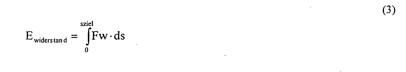
Weiterhin bestimmt die Berechnungseinrichtung 6 aus den bestimmten Teilenergien die
Gesamtenergie nach der Gleichung
In Figur 3 sind mehrere, beispielhafte Kennlinien dargestellt, die eine Zuordnung der
Rückstellkraft Fpedsoll in Abhängigkeit der überschüssigen Energie E bestimmen. In
Figur 3 ist auf der Abszisse 14 der Energiewert E aufgetragen, der sowohl positive, als
auch negative Werte annehmen kann. Auf der Ordinate 15 ist die Rückstellkraft Fpedsoll
aufgetragen, mit der das aktive Fahrpedal gegen den Widerstand des Fahrerfußes
gegendrückt. Da bei negativen Energiewerten E der Fahrer das Fahrpedal betätigen kann,
ohne dass diese Energie unmittelbar darauf durch einen Bremseneingriff vernichtet
werden muss, wird den negativen E-Werten eine Pedalrückstellkraft Fpedsoll = 0
zugeordnet. Bei positiven E-Werten wird erfindungsgemäß eine positive Rückstellkraft
Fpedsoll bestimmt, die umso größer wird, je größer der Energieüberschuss der momentan
im Fahrzeug gespeicherten Energie ist. Hierzu kann es beispielsweise vorgesehen sein,
dass gemäß Kennlinie 16 eine Ursprungshalbgerade vorgesehen ist, die die Rückstellkraft
Fpedsoll linear mit steigenden E-Werten zunehmen lässt. Weiterhin kann es gemäß
Kennlinie 17 vorgesehen sein, dass die Rückstellkraft Fpedsoll ebenfalls linear mit
positiven E-Werten korreliert ist, jedoch eine positive Rückstellkraft erst ab einem
Mindestenergiewert E1 vorgesehen ist. Weiterhin kann es gemäß Kennlinie 18 auch
möglich sein, die Rückstellkraft Fpedsoll quadratisch mit dem E-Wert ansteigen zu
lassen, so dass bei einer übermäßigen Fahrpedalbetätigung ein besonders starker
Rückstellkraftanstieg zu verzeichnen ist. Weiterhin kann es vorgesehen sein, dass gemäß
Kennlinie 19 bei Erreichen einer maximalen Rückstellkraft Fpedsollmax eine maximale
Pedalrückstellkraft erreicht wird, die auch bei weiter ansteigenden, positiven E-Werten
nicht weiter erhöht wird.FIG. 3 shows a plurality of exemplary characteristic curves which show an association of the
Restoring force Fpedsoll depending on the excess energy E determine. In
Figure 3 is plotted on the
In Figur 4 ist der Fahrpedalaktuator 12 dargestellt, der die Rückstellkraft Fpedsoll am
aktiven Fahrpedal 21 erzeugt. Hierzu wird dem Fahrpedalaktuator 12 der
Rückstellkraftwert Fpedsoll zugeführt, der von der
Rückstellkraftbestimmungseinrichtung 11 ermittelt wurde. Der Rückstellkraftsollwert
Fpedsoll wird einer Vergleichseinrichtung 20 zugeführt, der auch der tatsächliche,
momentan anliegende Rückstellkraftwert Fpedist zugeführt wird. Das Ausgangssignal der
Vergleichseinrichtung 20 wird dem aktiven Fahrpedal zugeführt, worauf dieses den Wert
Fpedist entsprechend erhöht oder vermindert, so dass zu jedem Zeitpunkt der berechnete
Pedalkraftsollwert Fpedsoll eingestellt wird. Weiterhin wird durch das aktive Fahrpedal
21 der momentane Fahrpedalwinkel α ermittelt und als Regelgröße einer
Motorsteuerung zugeführt. Gegebenenfalls kann der Fahrpedalwinkel α auch dazu
verwendet werden, die Fahrpedalrückstellkraft Fpedsoll zu beeinflussen und in
Abhängigkeit des Fahrpedalwinkels α die Rückstellkraft zu erhöhen oder zu vermindern.
Durch die Vergleichseinrichtung 20 wird gewährleistet, dass die tatsächliche Kraft
Fpedist der vorgegebenen Rückstellkraftgröße Fpedsoll folgt.In Figure 4, the
Claims (12)
Applications Claiming Priority (2)
| Application Number | Priority Date | Filing Date | Title |
|---|---|---|---|
| DE2003156834 DE10356834A1 (en) | 2003-12-05 | 2003-12-05 | Method and device for adjusting the restoring force acting on an accelerator pedal device |
| DE10356834 | 2003-12-05 |
Publications (3)
| Publication Number | Publication Date |
|---|---|
| EP1538018A2 true EP1538018A2 (en) | 2005-06-08 |
| EP1538018A3 EP1538018A3 (en) | 2006-09-20 |
| EP1538018B1 EP1538018B1 (en) | 2008-07-30 |
Family
ID=34442455
Family Applications (1)
| Application Number | Title | Priority Date | Filing Date |
|---|---|---|---|
| EP20040017289 Expired - Lifetime EP1538018B1 (en) | 2003-12-05 | 2004-07-22 | Method and device for setting the return force of a accelerator pedal |
Country Status (2)
| Country | Link |
|---|---|
| EP (1) | EP1538018B1 (en) |
| DE (2) | DE10356834A1 (en) |
Cited By (10)
| Publication number | Priority date | Publication date | Assignee | Title |
|---|---|---|---|---|
| EP1607263B1 (en) * | 2004-06-17 | 2007-08-22 | Robert Bosch Gmbh | Method and device for adjusting the force acting on a drive pedal |
| FR2904592A1 (en) * | 2006-08-04 | 2008-02-08 | Peugeot Citroen Automobiles Sa | Stopping distance estimating method for vehicle, involves applying corrective factor to kinetic energy of vehicle, and estimating necessary distance so that vehicle is stopped by itself from corrected kinetic energy |
| DE102007035424A1 (en) * | 2007-07-28 | 2009-01-29 | Dr. Ing. H.C. F. Porsche Aktiengesellschaft | Control interface for vehicle, has drive unit, where interface selects sailings of vehicle when output of unit is not introduced, so that vehicle is either propelled or braked when vehicle is brought into mode |
| WO2011003956A1 (en) * | 2009-07-09 | 2011-01-13 | Conti Temic Microelectronic Gmbh | Device for generating an additional restoring force at the gas pedal and method for the operation thereof |
| FR2951125A1 (en) * | 2009-10-09 | 2011-04-15 | Bosch Gmbh Robert | CONTROL APPARATUS AND METHOD FOR SELECTING THE RESISTANCE CHARACTERISTIC OF AN ACCELERATOR PEDAL |
| DE102010041539A1 (en) * | 2010-09-28 | 2012-03-29 | Bayerische Motoren Werke Aktiengesellschaft | Driver assistance system to support the driver for consumption-controlled driving |
| US9242653B2 (en) | 2010-09-28 | 2016-01-26 | Bayerische Motoren Werke Aktiengesellschaft | Driver assistance system for assisting the driver for the purpose of consumption-controlled driving |
| US9493071B2 (en) | 2010-09-28 | 2016-11-15 | Bayerische Motoren Werke Aktiengesellschaft | Driver assistance system for driver assistance for consumption controlled driving |
| US9802483B2 (en) | 2013-07-04 | 2017-10-31 | Conti Temic Microelectronic Gmbh | Accelerator force feedback pedal (AFFP) as assistance system for distance control in traffic |
| CN114683841A (en) * | 2020-12-30 | 2022-07-01 | 宝能汽车集团有限公司 | Control method and control system for preventing mistaken violent stepping on accelerator pedal |
Families Citing this family (2)
| Publication number | Priority date | Publication date | Assignee | Title |
|---|---|---|---|---|
| DE102008043756B4 (en) | 2008-11-14 | 2022-09-01 | Robert Bosch Gmbh | Method and control unit for providing traffic sign information |
| JP4881482B1 (en) * | 2011-06-02 | 2012-02-22 | 有限会社ジロウコレクション | Accelerator pedal pressure adjustment system for vehicles |
Family Cites Families (5)
| Publication number | Priority date | Publication date | Assignee | Title |
|---|---|---|---|---|
| DE4344369C2 (en) * | 1993-12-24 | 1997-12-11 | Daimler Benz Ag | Consumption-oriented mileage limitation of a vehicle drive |
| DE19620929A1 (en) * | 1996-05-24 | 1997-11-27 | Porsche Ag | Longitudinal control system for motor vehicles with accelerator pedal with feel characteristic |
| JP3536703B2 (en) * | 1999-02-09 | 2004-06-14 | 株式会社日立製作所 | Hybrid vehicle control method, hybrid vehicle control device, and hybrid vehicle |
| DE10026048C2 (en) * | 2000-05-25 | 2002-05-02 | Daimler Chrysler Ag | Haptic signaling device |
| US6559762B1 (en) * | 2002-01-02 | 2003-05-06 | Ford Global Technologies, Llc | Multi channel braking notification system |
-
2003
- 2003-12-05 DE DE2003156834 patent/DE10356834A1/en not_active Withdrawn
-
2004
- 2004-07-22 DE DE200450007725 patent/DE502004007725D1/en not_active Expired - Lifetime
- 2004-07-22 EP EP20040017289 patent/EP1538018B1/en not_active Expired - Lifetime
Cited By (13)
| Publication number | Priority date | Publication date | Assignee | Title |
|---|---|---|---|---|
| EP1607263B1 (en) * | 2004-06-17 | 2007-08-22 | Robert Bosch Gmbh | Method and device for adjusting the force acting on a drive pedal |
| FR2904592A1 (en) * | 2006-08-04 | 2008-02-08 | Peugeot Citroen Automobiles Sa | Stopping distance estimating method for vehicle, involves applying corrective factor to kinetic energy of vehicle, and estimating necessary distance so that vehicle is stopped by itself from corrected kinetic energy |
| DE102007035424A1 (en) * | 2007-07-28 | 2009-01-29 | Dr. Ing. H.C. F. Porsche Aktiengesellschaft | Control interface for vehicle, has drive unit, where interface selects sailings of vehicle when output of unit is not introduced, so that vehicle is either propelled or braked when vehicle is brought into mode |
| WO2011003956A1 (en) * | 2009-07-09 | 2011-01-13 | Conti Temic Microelectronic Gmbh | Device for generating an additional restoring force at the gas pedal and method for the operation thereof |
| FR2951125A1 (en) * | 2009-10-09 | 2011-04-15 | Bosch Gmbh Robert | CONTROL APPARATUS AND METHOD FOR SELECTING THE RESISTANCE CHARACTERISTIC OF AN ACCELERATOR PEDAL |
| US8849507B2 (en) | 2010-09-28 | 2014-09-30 | Bayerische Motoren Werke Aktiengesellschaft | Driver assistance system for driver assistance for consumption controlled driving |
| DE102010041539A1 (en) * | 2010-09-28 | 2012-03-29 | Bayerische Motoren Werke Aktiengesellschaft | Driver assistance system to support the driver for consumption-controlled driving |
| US9242653B2 (en) | 2010-09-28 | 2016-01-26 | Bayerische Motoren Werke Aktiengesellschaft | Driver assistance system for assisting the driver for the purpose of consumption-controlled driving |
| US9493071B2 (en) | 2010-09-28 | 2016-11-15 | Bayerische Motoren Werke Aktiengesellschaft | Driver assistance system for driver assistance for consumption controlled driving |
| US10960832B2 (en) | 2010-09-28 | 2021-03-30 | Bayerische Motoren Werke Aktiengesellschaft | Driver assistance system for driver assistance for consumption controlled driving |
| US10974670B2 (en) | 2010-09-28 | 2021-04-13 | Bayerische Motoren Werke Aktiengesellschaft | Driver assistance system for driver assistance for consumption controlled driving |
| US9802483B2 (en) | 2013-07-04 | 2017-10-31 | Conti Temic Microelectronic Gmbh | Accelerator force feedback pedal (AFFP) as assistance system for distance control in traffic |
| CN114683841A (en) * | 2020-12-30 | 2022-07-01 | 宝能汽车集团有限公司 | Control method and control system for preventing mistaken violent stepping on accelerator pedal |
Also Published As
| Publication number | Publication date |
|---|---|
| EP1538018B1 (en) | 2008-07-30 |
| DE502004007725D1 (en) | 2008-09-11 |
| EP1538018A3 (en) | 2006-09-20 |
| DE10356834A1 (en) | 2005-06-30 |
Similar Documents
| Publication | Publication Date | Title |
|---|---|---|
| DE102019124700B4 (en) | DRIVING CONTROL DEVICE FOR A VEHICLE | |
| DE102008039950B4 (en) | Method, device and road vehicle with a device for determining a driving profile for road vehicles | |
| DE10015300B4 (en) | Method and device for controlling the driving speed of a vehicle | |
| EP3191355B1 (en) | Distance control system for motor vehicles | |
| DE102010001045B4 (en) | Start-up assistant for motor vehicles | |
| WO2013064705A1 (en) | Method for determining an emergency braking situation of a vehicle | |
| EP3386823B1 (en) | Method for adaptively controlling a vehicle speed in a vehicle, and speed control system for carrying out the method | |
| EP1940665A1 (en) | Adaptive cruise control featuring recognition of a traffic jam | |
| EP1007384B1 (en) | Method and system for determining a target vehicle | |
| DE102022104168A1 (en) | METHODS AND SYSTEMS FOR A VEHICLE SUPPORT MEASURE | |
| DE102016211208A1 (en) | Advanced driver assistance procedure and system | |
| DE102015006445A1 (en) | Method and device for assisting a driver of a vehicle, in particular a utility vehicle | |
| EP1538018B1 (en) | Method and device for setting the return force of a accelerator pedal | |
| DE102009045512A1 (en) | Controller for driver assistance system, comprises accelerator pedal of motor vehicle, where controller is provided for selecting resistance characteristic that are provided by memory | |
| DE102014210174B4 (en) | Determining a critical vehicle condition and a minimum vehicle distance | |
| EP1276628B1 (en) | Method for adaptive distance and or driving speed adjustment in a motor vehicle | |
| EP3019376B1 (en) | Method and device for automatically regulating a longitudinal dynamic of a motor vehicle | |
| DE102022126726A1 (en) | DRIVER ASSISTANCE SYSTEM WITH A CRUISE CONTROL FUNCTION AND A PARKING ASSISTANCE FUNCTION, AS WELL AS A CORRESPONDING METHOD AND SOFTWARE FOR SUCH A METHOD | |
| EP1520745A2 (en) | Method and device for Recognising and adjusting left-hand or right hand driving | |
| DE10047048A1 (en) | Automatic acceleration, deceleration of vehicle, involves using deceleration formed by adding constant component, component increasing as distance decreases and a speed component | |
| EP3019375B1 (en) | Method and device for automatic longitudinal dynamics control of a motor vehicle | |
| EP4512680A1 (en) | Method for controlling an at least partially autonomous ego motor vehicle | |
| DE102016004852A1 (en) | Method for operating a vehicle | |
| DE102021116331A1 (en) | Method and device for prioritizing route events | |
| DE102006030676A1 (en) | Vehicle`s longitudinal movement controlling method, involves activating brake back-up mode during detection of object and delay request of driver, where delay adjusted by driver over acceleration plate is increased in brake back-up mode |
Legal Events
| Date | Code | Title | Description |
|---|---|---|---|
| PUAI | Public reference made under article 153(3) epc to a published international application that has entered the european phase |
Free format text: ORIGINAL CODE: 0009012 |
|
| AK | Designated contracting states |
Kind code of ref document: A2 Designated state(s): AT BE BG CH CY CZ DE DK EE ES FI FR GB GR HU IE IT LI LU MC NL PL PT RO SE SI SK TR |
|
| AX | Request for extension of the european patent |
Extension state: AL HR LT LV MK |
|
| PUAL | Search report despatched |
Free format text: ORIGINAL CODE: 0009013 |
|
| AK | Designated contracting states |
Kind code of ref document: A3 Designated state(s): AT BE BG CH CY CZ DE DK EE ES FI FR GB GR HU IE IT LI LU MC NL PL PT RO SE SI SK TR |
|
| AX | Request for extension of the european patent |
Extension state: AL HR LT LV MK |
|
| 17P | Request for examination filed |
Effective date: 20070320 |
|
| AKX | Designation fees paid |
Designated state(s): DE FR GB |
|
| 17Q | First examination report despatched |
Effective date: 20070801 |
|
| GRAP | Despatch of communication of intention to grant a patent |
Free format text: ORIGINAL CODE: EPIDOSNIGR1 |
|
| GRAS | Grant fee paid |
Free format text: ORIGINAL CODE: EPIDOSNIGR3 |
|
| GRAA | (expected) grant |
Free format text: ORIGINAL CODE: 0009210 |
|
| AK | Designated contracting states |
Kind code of ref document: B1 Designated state(s): DE FR GB |
|
| REG | Reference to a national code |
Ref country code: GB Ref legal event code: FG4D Free format text: NOT ENGLISH |
|
| REF | Corresponds to: |
Ref document number: 502004007725 Country of ref document: DE Date of ref document: 20080911 Kind code of ref document: P |
|
| PLBE | No opposition filed within time limit |
Free format text: ORIGINAL CODE: 0009261 |
|
| STAA | Information on the status of an ep patent application or granted ep patent |
Free format text: STATUS: NO OPPOSITION FILED WITHIN TIME LIMIT |
|
| 26N | No opposition filed |
Effective date: 20090506 |
|
| PGFP | Annual fee paid to national office [announced via postgrant information from national office to epo] |
Ref country code: FR Payment date: 20100802 Year of fee payment: 7 |
|
| PGFP | Annual fee paid to national office [announced via postgrant information from national office to epo] |
Ref country code: GB Payment date: 20100726 Year of fee payment: 7 |
|
| GBPC | Gb: european patent ceased through non-payment of renewal fee |
Effective date: 20110722 |
|
| REG | Reference to a national code |
Ref country code: FR Ref legal event code: ST Effective date: 20120330 |
|
| PG25 | Lapsed in a contracting state [announced via postgrant information from national office to epo] |
Ref country code: FR Free format text: LAPSE BECAUSE OF NON-PAYMENT OF DUE FEES Effective date: 20110801 |
|
| PG25 | Lapsed in a contracting state [announced via postgrant information from national office to epo] |
Ref country code: GB Free format text: LAPSE BECAUSE OF NON-PAYMENT OF DUE FEES Effective date: 20110722 |
|
| PGFP | Annual fee paid to national office [announced via postgrant information from national office to epo] |
Ref country code: DE Payment date: 20140925 Year of fee payment: 11 |
|
| REG | Reference to a national code |
Ref country code: DE Ref legal event code: R119 Ref document number: 502004007725 Country of ref document: DE |
|
| PG25 | Lapsed in a contracting state [announced via postgrant information from national office to epo] |
Ref country code: DE Free format text: LAPSE BECAUSE OF NON-PAYMENT OF DUE FEES Effective date: 20160202 |