EP1537937B1 - Modul einer widerstandsschweisszange - Google Patents
Modul einer widerstandsschweisszange Download PDFInfo
- Publication number
- EP1537937B1 EP1537937B1 EP04027830.1A EP04027830A EP1537937B1 EP 1537937 B1 EP1537937 B1 EP 1537937B1 EP 04027830 A EP04027830 A EP 04027830A EP 1537937 B1 EP1537937 B1 EP 1537937B1
- Authority
- EP
- European Patent Office
- Prior art keywords
- welding
- module
- welding gun
- gun housing
- housing according
- Prior art date
- Legal status (The legal status is an assumption and is not a legal conclusion. Google has not performed a legal analysis and makes no representation as to the accuracy of the status listed.)
- Expired - Lifetime
Links
Images
Classifications
-
- G—PHYSICS
- G01—MEASURING; TESTING
- G01N—INVESTIGATING OR ANALYSING MATERIALS BY DETERMINING THEIR CHEMICAL OR PHYSICAL PROPERTIES
- G01N29/00—Investigating or analysing materials by the use of ultrasonic, sonic or infrasonic waves; Visualisation of the interior of objects by transmitting ultrasonic or sonic waves through the object
- G01N29/04—Analysing solids
- G01N29/11—Analysing solids by measuring attenuation of acoustic waves
-
- B—PERFORMING OPERATIONS; TRANSPORTING
- B23—MACHINE TOOLS; METAL-WORKING NOT OTHERWISE PROVIDED FOR
- B23K—SOLDERING OR UNSOLDERING; WELDING; CLADDING OR PLATING BY SOLDERING OR WELDING; CUTTING BY APPLYING HEAT LOCALLY, e.g. FLAME CUTTING; WORKING BY LASER BEAM
- B23K11/00—Resistance welding; Severing by resistance heating
- B23K11/24—Electric supply or control circuits therefor
- B23K11/241—Electric supplies
-
- B—PERFORMING OPERATIONS; TRANSPORTING
- B23—MACHINE TOOLS; METAL-WORKING NOT OTHERWISE PROVIDED FOR
- B23K—SOLDERING OR UNSOLDERING; WELDING; CLADDING OR PLATING BY SOLDERING OR WELDING; CUTTING BY APPLYING HEAT LOCALLY, e.g. FLAME CUTTING; WORKING BY LASER BEAM
- B23K11/00—Resistance welding; Severing by resistance heating
- B23K11/24—Electric supply or control circuits therefor
- B23K11/25—Monitoring devices
- B23K11/252—Monitoring devices using digital means
-
- B—PERFORMING OPERATIONS; TRANSPORTING
- B23—MACHINE TOOLS; METAL-WORKING NOT OTHERWISE PROVIDED FOR
- B23K—SOLDERING OR UNSOLDERING; WELDING; CLADDING OR PLATING BY SOLDERING OR WELDING; CUTTING BY APPLYING HEAT LOCALLY, e.g. FLAME CUTTING; WORKING BY LASER BEAM
- B23K31/00—Processes relevant to this subclass, specially adapted for particular articles or purposes, but not covered by any single one of main groups B23K1/00 - B23K28/00
- B23K31/12—Processes relevant to this subclass, specially adapted for particular articles or purposes, but not covered by any single one of main groups B23K1/00 - B23K28/00 relating to investigating the properties, e.g. the weldability, of materials
-
- G—PHYSICS
- G01—MEASURING; TESTING
- G01N—INVESTIGATING OR ANALYSING MATERIALS BY DETERMINING THEIR CHEMICAL OR PHYSICAL PROPERTIES
- G01N2291/00—Indexing codes associated with group G01N29/00
- G01N2291/10—Number of transducers
- G01N2291/102—Number of transducers one emitter, one receiver
-
- G—PHYSICS
- G01—MEASURING; TESTING
- G01N—INVESTIGATING OR ANALYSING MATERIALS BY DETERMINING THEIR CHEMICAL OR PHYSICAL PROPERTIES
- G01N2291/00—Indexing codes associated with group G01N29/00
- G01N2291/26—Scanned objects
- G01N2291/267—Welds
- G01N2291/2672—Spot welding
Definitions
- the invention is in the field of resistance welding for use in seam welding, projection welding, or spot welding, and is concerned with housing components for operation within the welding gun body.
- the inventor proposes, inter alia, the integration of a power control with a welding transformer for cost reduction and more compact design. Due to the dimensions of the devices for power control in modern resistance welding systems (especially when using AC technology), the proposed combination still leads to a relatively heavy and cumbersome arrangement, which is unlikely to be suitable because of the weight and space requirements, in the housing of a welding gun to be carried by a welding robot.
- the system consisting of welding tongs + transformer
- the weight of this arrangement can easily reach 150 kg and more, with the transformer making a significant contribution to the weight. Therefore, the weight of the overall arrangement is a crucial factor for the dimensioning of the mechanics and the motion control of the welding robot (joints, load capacity, acceleration, etc.) and of course for the costs incurred. The lower the weight, the lower the requirements for the robot mechanics.
- the control of the mobile system is often realized locally in conjunction with a central robot controller.
- US 2002/0125219 A1 shows a modular servopneumatische welding gun having a welding gun housing according to the preamble of claim 1.
- US5166491A relates to a modular welding apparatus controlled by a master computer, a welding controller, and a power unit apparatus and method.
- a welding transformer is arranged outside a welding gun housing.
- US 4,734,555 A discloses a method and apparatus for measuring and controlling a depression in resistance welding.
- EP 0 830 916 A1 shows a motor-operated resistance spot welding machine.
- the object of the present invention is to achieve the most effective space utilization of the guided by the welding robot welding gun housing, taking into account the requirements of the weight to gain space in the welding box or cabinet and on the other to obtain a flexible and modular system as possible which does not impose too high mechanical demands on the welding robot, ie meets the requirements for the permissible maximum weight.
- the resistance welding system preferably monitors the welding process by means of ultrasound measurements and in particular serves for the production of spot welds or welds on sheet metal in bodywork, wherein the module is designed such that there are further module components which are relevant for carrying out the welding process monitored by the welding control. includes and the input or output variables of the module components are exchanged via the interface with welding gun components, in particular with electric drives and Ultrasonic transmitters and receivers, and the welding gun housing includes the module.
- this solution fulfills the requirements for the desired modularity because of the existing uniform interface.
- the module components could be realized, for example, as plug-in cards, so that, similar to an industrial PC, depending on the system configuration, corresponding functionalities can be retrofitted or replaced.
- this module could represent the interface to an externally connected control or power control as an input / main unit and standardized interfaces with the outside world communicate as it passes the signals within the welding gun housing to the appropriate components.
- a relevant module component is an at least partially integrated device for carrying out ultrasonic measurements for the purpose of testing welded joints and / or for controlling the welding process.
- Transverse waves are directed through the liquid welding point during the welding process via an ultrasonic transmitter and ultrasonic receiver. Since liquids, unlike solid materials, can not transfer lateral forces, the received signal changes with decreasing strength of the melting material.
- so-called transmission curves are recorded from which the instantaneous properties of the spot weld can be read off. This means that it is possible to infer whether the melt is too hot, too cold or optimally tempered, for example. This transmission curve is evaluated during the welding process by an ultrasonic controller.
- the curve can also be used to calculate the instantaneous spot diameter and the data can be statistically evaluated via software so that, in principle, every single spot weld can be logged.
- the above-mentioned solution makes it possible to remove the ultrasonic controller from the cabinet and attach it directly inside the welding gun housing, ie directly in the vicinity of the ultrasonic sensors. The complete production and / or processing of the ultrasonic measurement data would thus be possible on site and without long cable connections. Over a standardized interface could then the Measurement results are queried directly from a controller. Potential sources of error due to cable breakage or transmission errors could be minimized.
- the module is designed in such a way that one or even the only module component in the module is an at least partially or completely integrated converter (or only the power unit) with or without rectifier for the primary supply of an MF transformer, then in addition to the pure MF transformer function also its energy source housed within the module and thus the welding gun housing.
- the combination of a water-cooled MF transformer with / without rectifier would form together with the inverter a compact, self-contained unit, which would possibly also be used in other applications or would be transferable to other technologies.
- a component in the module is an at least partially integrated welding controller, for example to support a decentralized control architecture.
- Operating parameters such as holding time, current time, holding time and hold-open time could then u.a. be predetermined by this control.
- any combination of the aforementioned module components can be combined as needed and application so that there is an optimal utilization of the existing dust chamber in the welding gun body.
- the arrangement is particularly useful whenever co-operating devices, e.g. the ultrasonic sensors and the ultrasound controller or the welding tongs and the welding current regulator or, as already mentioned, the control are arranged directly in the module.
- co-operating devices e.g. the ultrasonic sensors and the ultrasound controller or the welding tongs and the welding current regulator or, as already mentioned, the control are arranged directly in the module.
- the extent to which complete integration of all components relevant for carrying out the welding process is possible is determined primarily by the semiconductor technology used and the welding currents required. Theoretically, full integration would already be conceivable
- the module components are advantageously releasably connected, for example via plug-in connections, to the interface of the module, so they are exchangeable at any time, e.g. in case of repair, and can be quickly and easily removed or introduced.
- the housing of the module is impermeable to dust, spray, spray or spray water (IP65 or IP66 or higher) designed to protect the internal electronics optimally against environmental influences.
- the transformer or rectifier cooling is extended so that it dissipates the heat generated by the module components with the same. Because of the increased heat dissipation, however, it may then be necessary to increase the coolant throughput or to replace the coolant itself with a coolant, with a higher heat absorption.
- the advantage of the invention is particularly useful when used in a production line for the realization of an industrial process, in particular for the bodywork, with welding robots on which welding tongs articulated are mounted, the welding guns are operated via a module with a cooled welding transformer with rectifier as a module integrated module component and with an interface for providing or recording required for the operation of welding guns equipped with a welding control resistance welding system electrical input or Output variables, wherein the resistance welding system preferably monitors the welding process by means of ultrasound measurements and in particular serves for the production of spot welds or welds on sheet metal in bodywork, the module being designed such that there are further module components which are relevant for carrying out the welding process monitored by the welding control, includes and the input and output variables of the module components are exchanged via the interface with welding gun components, in particular with electric drives and ultrasound transmitters and receivers, and the welding gun housing comprises the module and is carried along during welding.
- a decentralized organization and the highest possible outsourcing of system components taking advantage of all space reserves is of enormous importance in production lines.
- the invention helps to drastically reduce the costs of cabling and control of the components relevant to the welding process and thus also to save costs.
- This advantage is further enhanced in that the module is designed according to one of claims 2 to 11 and / or all attached to the welding guns modules are connected to a central welding control and / or central power supply.
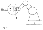
- FIG. 1 shows a welding robot 1 with welding gun housing 2 and module 3.
- the module 3 is housed in the welding gun housing 2, which is articulated on the pivotable arm of the robot and participates in all movement of the arm.
- the welding gun housing 2 is pivotable in all planes, so that even remote angles, for example within an automobile body by means of the welding electrodes 12 can be achieved.
- the electrical supply is ensured by the module 3, wherein the module 3 itself in turn communicates with the outside world via the arm of the welding robot, which holds the necessary supply lines ready.
- other components that are housed in the welding gun housing 2. These include: electric drives, ballscrews, water-cooled transformer with rectifier diodes, etc ..
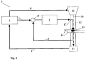
- FIG. 2 shows somewhat more detailed which function, for example, by means of the module 3 in the welding gun housing 2 could be realized.
- a module component of the module 3 the ultrasound controller 4, the current regulator 5, one of the subtraction circuit 15 supplied actual current 6 and nominal current 7, the ultrasonic transmission signal 8 and the ultrasonic received signal 9 with the ultrasonic transmitter 10 and .
- the welding current 17 and the transverse waves 16 are indicated.
- the module 3 comprises here as a possible module component the previously mentioned device for carrying out ultrasonic measurements for testing welded joints during the welding process.
- the ultrasonic controller 4 subjects the ultrasonic transmitter 10 to horizontally polarized transverse waves or shear waves 16. However, since liquid materials have no shear resistance, shear waves 16 can not propagate in them. The shear waves therefore travel through the welding tongs, which are usually made of copper, into the welding electrodes and then into the liquid spot weld. As the liquefaction of the weld zone increases, the characteristic properties of the shear waves conducted to the ultrasonic receiver 11 via the electrodes 12 and the welding guns change. This ultrasonic received signal 9 is received again by the ultrasound controller 4 and processed internally.
- the current setpoint 7 resulting from this processing and the measured current actual value 6 are obtained the current controller 5 via the subtraction point 15.
- a correction signal is available, with which the welding current 17 is set so that it generates a welding spot according to the requirements or a temperature according to the requirements in the spot weld.
- Other parameters influencing the weld joint would be the contact pressure of the welding electrodes or the duration of the welding process. Control devices which also influence these variables could additionally be integrated.
Landscapes
- Engineering & Computer Science (AREA)
- Mechanical Engineering (AREA)
- Physics & Mathematics (AREA)
- Acoustics & Sound (AREA)
- Health & Medical Sciences (AREA)
- Life Sciences & Earth Sciences (AREA)
- Chemical & Material Sciences (AREA)
- Analytical Chemistry (AREA)
- Biochemistry (AREA)
- General Health & Medical Sciences (AREA)
- General Physics & Mathematics (AREA)
- Immunology (AREA)
- Pathology (AREA)
- Resistance Welding (AREA)
Description
- Die Erfindung entspringt aus dem Bereich der Widerstandsschweißtechnik zur Verwendung beim Rollnahtschweißen, Buckelschweißen, oder Punktschweißen und befasst sich mit der Unterbringung von Komponenten zum Betrieb innerhalb des Schweißzangengehäuses.
- In der Offenlegungsschrift
US 2002/0134763 ist eine Vorrichtung für die Realisierung verschiedener Schweißströme mittels eines Inverters mit vereinfachtem Aufbau gezeigt und die SchriftUS 2001/0038000 offenbart ein Leistungsteil für eine Widerstandschweißanlage zur Bereitstellung der für den Schweißvorgang erforderlichen elektrischen Energie, insbesondere des Schweißstromes, mittels einer Inverterstromquelle. - In der
JP 04037480 A - In der täglichen Praxis kommt es jedoch häufig vor, dass das System, bestehend aus Schweißzange + Transformator, beweglich an einem Roboterarm (Schweißroboter) montiert wird. Das Gewicht dieser Anordnung kann schnell 150 kg und mehr betragen, wobei der Trafo einen wesentlichen Anteil am Gewicht ausmacht. Daher ist das Gewicht der Gesamtanordnung ein entscheidender Faktor für die Dimensionierung der Mechanik und die Bewegungsregelung des Schweißroboters (Gelenke, Tragkraft, Beschleunigung, etc.) und natürlich auch für die aufzuwendenen Kosten. Je geringer das Gewicht ist, desto geringer sind auch die Anforderungen an die Robotermechanik.
- Die Ansteuerung des beweglichen Systems wird oftmals örtlich fest in Verbindung mit einer zentralen Robotersteuerung realisiert.
-
US 2002/0125219 A1 zeigt eine modulare servopneumatische Schweißzange die ein Schweißzangengehäuse gemäß dem Oberbegriff von Patentanspruch 1 aufweist. -
US5166491A bezieht sich auf eine von einem Mastercomputer gesteuerte modulare Schweißvorrichtung, eine Schweißsteuerung und eine Leistungseinheitvorrichtung und -verfahren. Hier ist ein Schweißtransformator außerhalb eines Schweißzangengehäuses angeordnet. -
US 4,734,555 A offenbart ein Verfahren und eine Vorrichtung zum Messen und Steuern einer Vertiefung beim Widerstandsschweißen. -
EP 0 830 916 A1 zeigt eine motorbetriebene Widerstandspunktschweißmaschine. - Die Aufgabe der vorliegenden Erfindung ist es, unter Berücksichtigung der Anforderungen an das Gewicht eine möglichst effektive Raumausnutzung des vom Schweißroboter geführten Schweißzangengehäuses zu erreichen, um zum einen Raumbedarf im Schweißkoffer bzw. Schaltschrank zu gewinnen und zum anderen ein möglichst flexibles und modular aufgebautes System zu erhalten, welches keine allzu hohen mechanischen Anforderungen an den Schweißroboter stellt, also die Anforderungen an das zulässige Maximalgewicht erfüllt.
- Diese Aufgabe wird durch ein Schweißzangengehäuse gemäß Patentanspruch 1 gelöst.
- Vorteilhafte weitere Ausgestaltungen des Schweißzangengehäuses sind in den abhängigen Patentansprüchen dargelegt.
- Der Platzbedarf, der nur ca. 30 % eines für AC-Technik konzipierten Trafos beträgt, und ganz besonders auch das Gewicht für den bisher von der Anmelderin verwendeten MF-Schweißtransformator konnte durch den Einsatz eines kleineren, fortschrittlichen MF-Schweißtransformatoren gleicher Leistung annähernd halbiert werden. Neben der hierdurch erreichten Gewichtsersparnis wurde zusätzlich Platz im Schweißzangengehäuse gewonnen. Dieser gewonnene Raum wird nun erfindungsgemäß durch ein Modul mit einem gekühlten Schweißtransformator und mit Gleichrichter als in das Modul integrierte Modulkomponente sowie mit einer Schnittstelle zur Bereitstellung bzw. Aufnahme der für den Betrieb von Schweißzangen einer mit einer Schweißsteuerung ausgestatteten Widerstandsschweißanlage erforderlichen elektrischen Eingangs- bzw. Ausgangsgrößen eingenommen, wobei die Widerstandsschweißanlage vorzugsweise über Ultraschallmessungen den Schweißprozess überwacht und insbesondere zur Herstellung von Schweißpunkten bzw. Schweißnähten an Blechen im Karosseriebau dient, wobei das Modul so ausgebildet ist, dass es weitere Modulkomponenten, die zur Durchführung des von der Schweißsteuerung überwachten Schweißprozesses relevant sind, umfasst und die Eingangs- bzw. Ausgangsgrößen der Modulkomponenten über die Schnittstelle mit Schweißzangenkomponenten ausgetauscht werden, insbesondere mit elektrischen Antrieben sowie Ultraschallsendern und -empfängern, und das Schweißzangengehäuse das Modul umfasst. Dies schafft einerseits zusätzlichen Stauraum im Schaltschrank bzw. Schweißkoffer und andererseits erfüllt diese Lösung die Anforderungen an die gewünschte Modularität wegen der vorhandenen einheitlichen Schnittstelle.
- Die Modulkomponenten könnten beispielsweise als Steckkarten realisiert werden, so dass ähnlich wie bei einem Industrie PC je nach Systemkonfiguration entsprechende Funktionalitäten nachgerüstet oder ausgetauscht werden können.
- Würde man ein Modul vorteilhafterweise so ausbilden, dass es zur Zusammenführung und Weiterleitung von Schweißzangensignalen und Signalen der Trafosensorik dient, so könnte dieses Modul als Input/Ouptut-Einheit die Schnittstelle zu einer extern angeschlossenen Steuerung bzw. Leistungsregelung darstellen und über genormte Schnittstellen mit der Außenwelt kommunizieren, während es die Signale innerhalb des Schweißzangengehäuses an die entsprechenden Komponenten weiterleitet.
- Ganz besonders vorteilhaft wäre es, wenn eine relevante Modulkomponente eine zumindest teilweise integrierte Vorrichtung zur' Durchführung von Ultraschallmessungen zu Zwecken der Prüfung von Schweißverbindungen und/oder zur Regelung des Schweißvorganges ist. Über einen Ultraschallsender und Ultraschallempfänger werden hierzu Transversalwellen durch den flüssigen Schweißpunkt während des Schweißvorganges geleitet. Da Flüssigkeiten im Gegensatz zu festen Materialien keine Querkräfte übertragen können, verändert sich das empfangene Signal mit abnehmender Festigkeit des schmelzenden Materials. Es werden abhängig von den sich verändernden Eigenschaften des Schweißpunktes sogenannte Transmissionskurven aufgezeichnet, aus der die momentanen Eigenschaften des Schweißpunktes abgelesen werden kann. Das heißt es ist ein Rückschluss möglich, ob die Schmelze beispielsweise zu heiß, zu kalt oder optimal temperiert ist. Diese Transmissionskurve wird während des Schweißvorganges ausgewertet von einem Ultraschallregler. Aus der Kurve lässt sich auch der momentane Schweißpunktdurchmesser berechnen und über eine Software werden die Daten statistisch auswertbar, so dass im Prinzip jeder einzelne Schweißpunkt protokolliert werden kann. Die oben genannte Lösung gestattet es, den Ultraschallregler aus dem Schaltschrank herauszunehmen und direkt innerhalb des Schweißzangengehäuses anzubringen, also direkt in der Nähe der Ultraschallsensoren. Die komplette Erzeugung und/oder Verarbeitung der Ultraschallmessdaten wäre somit vor Ort und ohne lange Kabelverbindungen realisierbar. Über eine genormte Schnittstelle könnten dann die Messergebnisse direkt von einer Steuerung abgefragt werden. Potentielle Fehlerquellen durch Kabelbruch oder Übertragungsfehler könnten minimiert werden.
- Wird das Modul so ausgestaltet, dass eine oder gar die einzige Modulkomponente im Modul ein zumindest teilweise oder auch vollständig integrierter Umrichter (oder nur das Leistungsteil) mit oder ohne Gleichrichter zur primärseitigen Versorgung eines MF-Transformators ist, dann wäre neben der reinen MF-Trafofunktion auch dessen Energiequelle innerhalb des Moduls und damit des Schweißzangengehäuses untergebracht. Somit würde die Kombination aus einem wassergekühlten MF-Transformator mit/ohne Gleichrichter zusammen mit dem Umrichter eine kompakte, selbständige Einheit bilden, die ggf. auch in anderen Anwendungen Verwendung finden würde oder auch auf andere Technologien übertragbar wäre.
- Ein weiterer Vorteil ergäbe sich durch die zumindest teilweise Unterbringung von Vorrichtungen zur Regelung des Schweißstromes im Modul, so dass der erforderliche Platzbedarf im Schaltschrank bzw. Schweißkoffer, der in der Regel auf oder an der Robotersteuerung platziert ist, reduziert werden oder komplett entfallen kann.
- Auch könnte vorteilhaft eine Komponente zur Auswertung der Sensoren von Schweißzangenmotoren und/oder deren Ansteuerung zur Kraft- und Lageregelung in das Modul integriert werden, dies würde einen weiteren Beitrag zur Modularität der Gesamtanordnung beitragen und alle zur Nutzung der Schweißzangen erforderlichen Komponenten an einem zentralen Montageort ohne lange Wege vereinen. In der Regel sind in Schweißzangen zwei Achsen beispielsweise durch elektrische Motoren anzusteuern. Die o.g. Ansteuerung könnte also zwei Antriebsregler beinhalten, d.h. für jede Achse einen. Eine Achse übernimmt dabei den Zangenausgleich, die zweite Achse führt die Elektroden während des Schweißvorganges und betätigt den Druckzylinder zur Realisierung des Arbeitshubes oder des Vorhubes im Wartungsfalle. Als Verbindungsglied zwischen Motorabtrieb und Zange dienen im Falle von rotationssymmetrischen Motoren Kugelumlaufspindeln. Bei Verwendung von Linearmotoren wäre auch ein direkter Antrieb machbar.
- Maximale Modularität und Platzeinsparung wäre dann gewährleistet, wenn eine Komponente im Modul eine zumindest teilweise integrierte Schweißsteuerung ist, um zum Beispiel eine dezentral organisierte Steuerungsarchitektur zu unterstützten. Betriebsparameter wie Vorhaltezeit, Stromzeit, Nächhaltezeit und Offenhaltezeit könnten dann u.a. durch diese Steuerung vorgegeben werden.
- Selbstverständlich können beliebige Kombinationen der zuvor erwähnten Modulkomponenten je nach Bedarf und Anwendungsfall so kombiniert werden, dass sich eine optimale Ausnutzung des vorhandenen Staubraumes im Schweißzangengehäuse ergibt. Besonders nützlich ist die Anordnung immer dann, wenn zusammen agierende Vorrichtungen, wie z.B. die Ultraschallsensoren und der Ultraschallregler oder die Schweißzangen und der Schweißstromregler oder wie schon erwähnt auch die Steuerung, direkt im Modul angeordnet sind. Inwieweit eine vollständige Integration aller zur Durchführung des Schweißprozesses relevanten Komponenten möglich ist, wird in erster Linie von der verwendeten Halbleitertechnologie und den erforderlichen Schweißströmen bestimmt. Theoretisch wäre eine Vollintegration schon jetzt denkbar
- Es werden zur Lösung kundenspezifischer Anforderungen für unterschiedliche Zangenfunktiönen zum Beispiel folgende Varianten vom Anmelder favorisiert:
- 1. Für die Trafogrundfunktion kann mittel eines Multikontaktsteckers oder einer PG-Verschraubung der Leistungsanschluss hergestellt werden. Die Trafosensorik wird über eine Klemme bzw. einen kundenspezifischen Anschluss weitergeleitet und es besteht die Möglichkeit verschieden Zangensignale im Modul zusammenzuführen und über eine gemeinsame Schnittstelle (z.B. über den Roboter) zur übergeordneten Steuerung zu führen.
- 2. Zusätzlich zu 1. bildet die Funktion Ultraschallmessung mit der Ansteuerung der Ultraschall-Sensorik bzw. Ultraschall-Elektronik und die Verwendung eines Feldbusses (evtl. CAN) zum Umrichter eine oder mehrere Modulkomponenten des Moduls.
- 3. Zusätzlich zu 1. wird die Funktion "Servozange" (Regelung der Motorleistung, Verarbeitung der Sensorik von Druck und Ausgleichsmotor, Codierung) in das Modul integriert.
- 4. Zusätzlich zu 3. wird die in 2. erwähnte Ultraschallmessung als Modulkomponente in das Modul integriert.
- Die Modulkomponenten werden vorteilhafterweise lösbar, beispielsweise über Steckverbindungen, mit der Schnittstelle des Moduls elektrisch verbunden, so sind sie jederzeit austauschbar, z.B. im Reparaturfalle, und können schnell und leicht entfernt bzw. eingebracht werden.
- Wegen der häufig sehr widrigen Umstände im Umfeld der Anordnung wird das Gehäuse des Moduls undurchlässig für Staub, Strahl-, Spritz- oder Sprühwasser (IP65 oder IP66 oder höher) ausgebildet, um die interne Elektronik optimal vor Umwelteinflüssen zu schützen.
- Da abhängig von der Art der Modulkomponenten auch eine Kühlung erforderlich werden kann, z.B. speziell, wenn es sich um Leistungskomponenten handelt, wird die Transformator- bzw. Gleichrichterkühlung erweitert, so dass sie die von den Modulkomponenten entstehende Wärme gleich mit abführt. Wegen der gesteigerten Wärmeabfuhr wird es dann allerdings ggf. erforderlich den Kühlmitteldurchsatz zu erhöhen oder das Kühlmittel selbst durch ein Kühlmittel,mit höherer Wärmeaufnahme zu ersetzen.
- Es bietet sich außerdem an die Energieversorgung des Moduls ebenfalls in das Modulgehäuse zu integrieren und über die Netzspannung eine Gleichspannung zu realisieren oder einen extern oder auch intern erzeugten Leistungstakt heranzuziehen. Dies würde einen weiteren Beitrag zur Integration des Gesamtsystems leisten.
- Der Vorteil der Erfindung kommt ganz besonders zum Tragen, wenn sie eingesetzt wird in einer Fertigungsstraße zur Realisierung eines industriellen Prozesses, insbesondere für den Karosseriebau, mit Schweißrobotern an denen Schweißzangen gelenkig angebracht sind, wobei die Schweißzangen betrieben sind über ein Modul mit einem gekühlten Schweißtransformator mit Gleichrichter als in das Modul integrierte Modulkomponente sowie mit einer Schnittstelle zur Bereitstellung bzw. Aufnahme der für den Betrieb von Schweißzangen einer mit einer Schweißsteuerung ausgestatteten Widerstandsschweißanlage erforderlichen elektrischen Eingangs- bzw. Ausgangsgrößen, wobei die Widerstandsschweißanlage vorzugsweise über Ultraschallmessungen den Schweißprozess überwacht und insbesondere zur Herstellung von Schweißpunkten bzw. Schweißnähten an Blechen im Karosseriebau dient, wobei das Modul so ausgebildet ist, dass es weitere Modulkomponenten, die zur Durchführung des von der Schweißsteuerung überwachten Schweißprozesses relevant sind, umfasst und die Eingangs- bzw. Ausgangsgrößen der Modulkomponenten über die Schnittstelle mit Schweißzangenkomponenten ausgetauscht werden, insbesondere mit elektrischen Antrieben sowie Ultraschallsendern und -empfängern, und das Schweißzangengehäuse das Modul umfasst und beim Schweißen mitgeführt ist.
- Eine dezentrale Organisation und die möglichst hohe Auslagerung von Systemkomponenten unter Ausnutzung aller Platzreserven ist bei Fertigungsstraßen von enormer Bedeutung. Die Erfindung hilft die Aufwände bzgl. der Verkabelung und Ansteuerung der für den Schweißvorgang relevanten Komponenten drastisch zu reduzieren und damit auch Kosten einzusparen. Dieser Vorteil wird dadurch noch gesteigert, dass das Modul nach einem der Ansprüche 2 bis 11 ausgebildet ist und/oder alle an den Schweißzangen angebrachten Module an eine zentrale Schweißsteuerung und/oder zentrale Energieversorgung angebunden sind.
- Nachfolgend wird anhand von Zeichnung 1 die Grundidee der Erfindung nochmals erläutert und anhand der
Figur 2 ein mögliches Anwendungsbeispiel grob schematisch gezeigt. Gleiche Bezugszeichen in unterschiedlichen oder gleichen Figuren bezeichnen identische Komponenten. -
Figur 1 zeigt einen Schweißroboter 1 mit Schweißzangengehäuse 2 und Modul 3. Das Modul 3 ist im Schweißzangengehäuse 2 untergebracht, welches am schwenkbaren Arm des Roboters gelenkig gelagert ist und alle Bewegung des Armes mitmacht. - Das Schweißzangengehäuse 2 ist in allen Ebenen schwenkbar, so dass auch entlegene Winkel, beispielsweise innerhalb einer Automobilkarosserie mittels der Schweißelektroden 12 erreicht werden können. Die elektrische Versorgung wird durch das Modul 3 gewährleistet, wobei das Modul 3 selbst wiederum über den Arm den Schweißroboters, welcher die nötigen Versorgungsleitungen bereit hält, mit der Außenwelt kommuniziert. Nicht gezeigt sind hier weitere Komponenten, die im Schweißzangengehäuse 2 untergebracht sind. Es gehören hierzu unter anderem: elektrische Antriebe, Kugelumlaufspindeln, wassergekühlter Transformator mit Gleichrichterdioden, usw..
-
Figur 2 zeigt etwas detaillierter welche Funktion zum Beispiel mittels des Moduls 3 im Schweißzangengehäuse 2 realisierbar wäre. Es sind dargestellt eine Modulkomponente des Moduls 3, der Ultraschallregler 4, der Stromregler 5, ein der Subtraktionsschaltung 15 zugeführter Ist-Strom 6 und Soll-Strom 7, das Ultraschall-Sendesignal 8 und das Ultraschall-Empfangssignal 9 mit dem Ultraschall-Sender 10 bzw. -Empfänger 11 sowie die Schweißelektroden 12 und ein beispielhafter Schweißpunkt 13 zur Verbindung der Materialien 14. Weiter sind der Schweißstrom 17 und die Transversalwellen 16 angedeutet. - Das Modul 3 umfasst hier als eine mögliche Modulkomponente die zuvor bereits erwähnte Vorrichtung zur Durchführung von Ultraschallmessungen zur Prüfung von Schweißverbindungen während des Schweißvorganges. Der Ultraschallregler 4 beaufschlagt den Ultraschallsender 10 mit horizontal polarisierten Transversalwellen bzw. Scherwellen 16. Da flüssige Materialien jedoch keinen Scherwiderstand aufweisen, können sich Scherwellen 16 in ihnen auch nicht ausbreiten. Die Scherwellen wandern also durch die meist aus Kupfer hergestellten Schweißzangen in die Schweißelektroden und dann in den flüssigen Schweißpunkt. Mit zunehmender Verflüssigung der Schweißzone ändern sich damit die charakteristischen Eigenschaften der zum Ultraschallempfänger 11 über die Elektroden 12 und die Schweißzangen geleiteten Scherwellen. Dieses Ultraschall-Empfangssignal 9 wird von dem Ultraschallregler 4 wieder empfangen und intern verarbeitet. Den aus dieser Bearbeitung resultierenden Stromsollwert 7 und den gemessenen Stromistwert 6 erhält der Stromregler 5 über den Subtraktionspunkt 15. Damit steht ein Korrektursignal zur Verfügung, mit dem der Schweißstrom 17 so eingestellt wird, dass er einen den Anforderungen gemäßen Schweißpunkt bzw. eine den Anforderungen gemäße Temperatur im Schweißpunkt erzeugt. Weitere Parameter zur Beeinflussung der Schweißverbindung wären der Anpressdruck der Schweißelektroden oder auch die Dauer des Schweißvorganges. Regeleinrichtungen die auch diese Größen beeinflussen, könnten zusätzlich noch integriert werden. Bei Verwendung in einer Fertigungsstraße ist der erfindungsgemäße Vorteil schnell ersichtlich, da die Ultraschallregelung nun dezentral organisiert ist und die Maßnahmen zur Optimierung der Schweißverbindung unmittelbar am Entstehungsort des Schweißpunktes durchgeführt werden können.
-
- 1
- Schweißroboter
- 2
- Schweißzangengehäuse
- 3
- Modul
- 4
- Ultraschallregler
- 5
- Stromregler
- 6
- Ist-Strom
- 7
- Soll-Strom
- 8
- Ultraschall-Sendesignal
- 9
- Ultraschall-Empfangssignal
- 10
- Ultraschall-Sender
- 11
- Ultraschallempfänger
- 12
- Schweißelektroden
- 13
- Schweißpunkt
- 14
- Material
- 15
- Subtraktionspunkt
- 16
- Scherwellen
- 17
- Schweißstrom
Claims (14)
- Schweißzangengehäuse (2) für eine mit einer Schweißsteuerung ausgestattete Widerstandsschweißanlage, welche zur Herstellung von Schweißpunkten (13) bzw. Schweißnähten an Blechen im Karosseriebau ausgestaltet ist, wobei das Schweißzangengehäuse ein Modul (3) umfasst,
dadurch gekennzeichnet, dass
das Modul (3) umfasst
einen durch eine Kühlung kühlbaren MF-Schweißtransformator mit Gleichrichter, wobei der MF-Schweißtransformator derart klein bauend ausgestaltet ist, dass er eine in das Modul (3) integrierte Modulkomponente ist,
mindestens eine weitere in das Modul integrierte Modulkomponente zur Bereitstellung und/oder Aufnahme von elektrischen Signalen, die zur Durchführung des von der Schweißsteuerung überwachten Schweißprozesses relevant sind, und
eine Schnittstelle zur Bereitstellung und/oder Aufnahme der für den Betrieb von Schweißzangen erforderlichen elektrischen Eingangs- und/oder Ausgangsgrößen, wobei die elektrischen Eingangs- und/oder Ausgangsgrößen elektrische Signale, die zwischen der mindestens einen weiteren Modulkomponente und der Schweißsteuerung auszutauschen sind, und Größen für den Leistungsanschluss des MF-Schweißtransformators umfassen. - Schweißzangengehäuse gemäß Anspruch 1, dadurch gekennzeichnet, dass die Schnittstelle als eine Modulkomponente ausgestaltet ist zur Zusammenführung und Weiterleitung von Schweißzangensignalen und Signalen der Trafosensorik.
- Schweißzangengehäuse gemäß einem der vorherigen Ansprüche, dadurch gekennzeichnet, dass eine relevante Modulkomponente eine zumindest teilweise integrierte Vorrichtung zur Durchführung von Ultraschallmessungen zur Prüfung von Schweißverbindungen während des Schweißvorganges ist.
- Schweißzangengehäuse gemäß einem der vorherigen Ansprüche, dadurch gekennzeichnet, dass eine Modulkomponente ein zumindest teilweise integrierter Umrichter zur primärseitigen Versorgung des Transformators ist, wobei der Umrichter mit oder ohne Gleichrichter und der MF-Schweißtransformator mit oder ohne Gleichrichter ausgestaltet ist.
- Schweißzangengehäuse gemäß einem der vorherigen Ansprüche, dadurch gekennzeichnet, dass eine Modulkomponente eine zumindest teilweise integrierte Vorrichtung zur Bereitstellung und Regelung des Schweißstromes (17) ist.
- Schweißzangengehäuse gemäß einem der vorherigen Ansprüche, dadurch gekennzeichnet, dass eine Modulkomponente zur Auswertung der Sensoren von Schweißzangenmotoren und/oder deren Ansteuerung dient.
- Schweißgehäuse gemäß einem der vorherigen Ansprüche, dadurch gekennzeichnet, dass eine Modulkomponente eine zumindest teilweise integrierte Schweißsteuerung ist.
- Schweißzangengehäuse gemäß einem der vorherigen Ansprüche, dadurch gekennzeichnet, dass die Modulkomponenten lösbar, beispielsweise über Steckverbindungen, mit der Schnittstelle des Moduls (3) elektrisch verbunden sind.
- Schweißzangengehäuse gemäß einem der vorherigen Ansprüche, dadurch gekennzeichnet, dass das Gehäuse des Moduls (3) undurchlässig für Staub, Strahl-, Spritz- oder Sprühwasser, insbesondere gemäß IP65 oder IP66 oder höher, ausgebildet ist.
- Schweißzangengehäuse gemäß einem der vorherigen Ansprüche, dadurch gekennzeichnet, dass der MF-Schweißtransformator derart kühlbar ist, dass die von den Modulkomponenten entstehende Wärme über die Kühlung abgeführt ist.
- Schweißzangengehäuse gemäß einem der vorherigen Ansprüche, dadurch gekennzeichnet, dass die Energieversorgung des Moduls (3) ebenfalls in das Modulgehäuse integriert ist und über die Netzspannung eine Gleichspannung oder ein Leistungstakt realisiert ist.
- Schweißzangengehäuse gemäß einem der vorherigen Ansprüche, dadurch gekennzeichnet, dass die Modulkomponenten als Steckkarten realisiert sind.
- Fertigungsstraße zur Realisierung eines industriellen Prozesses, insbesondere für den Karosseriebau, mit Schweißrobotern an denen Schweißzangen gelenkig angebracht sind, wobei das Schweißzangengehäuse nach einem der vorhergehenden Ansprüche ausgebildet ist.
- Fertigungsstraße nach Anspruch 13, wobei alle an den Schweißzangen angebrachten Module (3) an eine zentrale Schweißsteuerung und/oder zentrale Energieversorgung angebunden sind.
Applications Claiming Priority (2)
| Application Number | Priority Date | Filing Date | Title |
|---|---|---|---|
| DE10356978 | 2003-12-05 | ||
| DE10356978A DE10356978A1 (de) | 2003-12-05 | 2003-12-05 | Modul einer Widerstandsschweißzange |
Publications (2)
| Publication Number | Publication Date |
|---|---|
| EP1537937A1 EP1537937A1 (de) | 2005-06-08 |
| EP1537937B1 true EP1537937B1 (de) | 2016-08-17 |
Family
ID=34442470
Family Applications (1)
| Application Number | Title | Priority Date | Filing Date |
|---|---|---|---|
| EP04027830.1A Expired - Lifetime EP1537937B1 (de) | 2003-12-05 | 2004-11-24 | Modul einer widerstandsschweisszange |
Country Status (4)
| Country | Link |
|---|---|
| US (1) | US7247810B2 (de) |
| EP (1) | EP1537937B1 (de) |
| JP (1) | JP2005169505A (de) |
| DE (1) | DE10356978A1 (de) |
Families Citing this family (5)
| Publication number | Priority date | Publication date | Assignee | Title |
|---|---|---|---|---|
| JP2010500581A (ja) | 2006-08-14 | 2010-01-07 | ジーイー センシング アンド インスペクション テクノロジーズ ゲゼルシャフト ミット ベシュレンクテル ハフツング | 電気抵抗溶接を利用して作製される溶接点のオンライン超音波検査方法 |
| AT512063B1 (de) * | 2011-10-31 | 2016-01-15 | Fronius Int Gmbh | Stromquelle und verfahren zur kühlung einer solchen stromquelle |
| JP5780170B2 (ja) * | 2012-02-08 | 2015-09-16 | トヨタ自動車株式会社 | スポット溶接装置及びスポット溶接方法 |
| US8657179B1 (en) * | 2012-03-26 | 2014-02-25 | The United States Of America As Represented By The Administrator Of The National Aeronautics And Space Administration | Weld nugget temperature control in thermal stir welding |
| KR102166234B1 (ko) * | 2020-01-28 | 2020-10-16 | 한국 오바라 주식회사 | 저항 스폿 용접 제어 시스템 및 그 방법 |
Citations (2)
| Publication number | Priority date | Publication date | Assignee | Title |
|---|---|---|---|---|
| DE10203246A1 (de) * | 2002-01-21 | 2003-08-21 | Bombardier Transp Gmbh | Mittelfrequenz-Transformator |
| EP1729310A1 (de) * | 2005-06-02 | 2006-12-06 | STS Spezial-Transformatoren-Stockach GmbH & Co. KG | MF-Transformator |
Family Cites Families (20)
| Publication number | Priority date | Publication date | Assignee | Title |
|---|---|---|---|---|
| US4577085A (en) * | 1984-01-20 | 1986-03-18 | Marelco Power Systems, Inc. | System of transformers for a welding apparatus |
| US4734555A (en) | 1986-06-26 | 1988-03-29 | Duffers Scientific, Inc. | Method and apparatus for measuring and controlling indentation in resistance welding |
| US5166491A (en) | 1987-12-15 | 1992-11-24 | Kabushiki Kaisha Toshiba | Master computer controlled modular welder, weld control and power unit apparatus and method |
| US4985612A (en) * | 1987-12-15 | 1991-01-15 | Kabushiki Kaisha Toshiba | Master computer controlled modular welder, weld control, and power unit apparatus and method |
| GB2225972B (en) * | 1988-12-15 | 1993-05-26 | Honda Motor Co Ltd | Resistance welding apparatus |
| JPH0437480A (ja) * | 1990-05-31 | 1992-02-07 | Suzuki Motor Corp | スポット溶接装置 |
| ATE167300T1 (de) * | 1992-07-31 | 1998-06-15 | Fraunhofer Ges Forschung | Verfahren zur bewertung von schweissverbindungen |
| DE4306492C1 (de) * | 1993-03-03 | 1994-07-21 | Wolfram Dr Ing Rennau | Schweißzangenregelung |
| IT1268100B1 (it) * | 1994-10-07 | 1997-02-20 | Stola Spa | Dispositivo per la saldatura di scocche di autoveicolo o di loro sotto-gruppi. |
| US5601741A (en) * | 1994-11-18 | 1997-02-11 | Illinois Tool Works, Inc. | Method and apparatus for receiving a universal input voltage in a welding power source |
| JPH08286725A (ja) * | 1995-04-13 | 1996-11-01 | Miyachi Technos Corp | 抵抗溶接用又はレーザ加工用端末ユニット、抵抗溶接又はレーザ加工制御装置、端末ユニット稼働方法 |
| GB2315135B (en) * | 1996-07-10 | 2000-12-06 | Honda Motor Co Ltd | Control apparatus for welding robot |
| EP0830916B1 (de) | 1996-09-13 | 2001-12-05 | Dengensha Manufacturing Company Limited | Motorisch betätigte Widerstands-Punktschweissmaschine |
| US20010003800A1 (en) * | 1996-11-21 | 2001-06-14 | Steven J. Frank | Interventional photonic energy emitter system |
| US6297467B1 (en) * | 1999-04-01 | 2001-10-02 | Daimlerchrysler Corporation | Transducer built into an electrode |
| US6870121B2 (en) * | 1999-08-17 | 2005-03-22 | Milco Manufacturing Co. | Modular welding guns |
| US6455800B1 (en) | 2001-01-04 | 2002-09-24 | Festo Corporation | Servo-pneumatic modular weld gun |
| DE10114323A1 (de) * | 2001-03-25 | 2002-09-26 | Matuschek Mestechnik Gmbh | Vorrichtung zum Widerstandsschweißen |
| US6978178B2 (en) * | 2002-04-30 | 2005-12-20 | Medtronic, Inc. | Method and apparatus for selecting an optimal electrode configuration of a medical electrical lead having a multiple electrode array |
| US7225035B2 (en) * | 2004-06-24 | 2007-05-29 | Medtronic, Inc. | Multipolar medical electrical lead |
-
2003
- 2003-12-05 DE DE10356978A patent/DE10356978A1/de not_active Ceased
-
2004
- 2004-11-24 EP EP04027830.1A patent/EP1537937B1/de not_active Expired - Lifetime
- 2004-12-02 US US11/001,991 patent/US7247810B2/en not_active Expired - Lifetime
- 2004-12-06 JP JP2004352731A patent/JP2005169505A/ja active Pending
Patent Citations (2)
| Publication number | Priority date | Publication date | Assignee | Title |
|---|---|---|---|---|
| DE10203246A1 (de) * | 2002-01-21 | 2003-08-21 | Bombardier Transp Gmbh | Mittelfrequenz-Transformator |
| EP1729310A1 (de) * | 2005-06-02 | 2006-12-06 | STS Spezial-Transformatoren-Stockach GmbH & Co. KG | MF-Transformator |
Also Published As
| Publication number | Publication date |
|---|---|
| EP1537937A1 (de) | 2005-06-08 |
| US7247810B2 (en) | 2007-07-24 |
| DE10356978A1 (de) | 2005-07-14 |
| JP2005169505A (ja) | 2005-06-30 |
| US20050127047A1 (en) | 2005-06-16 |
Similar Documents
| Publication | Publication Date | Title |
|---|---|---|
| DE69933271T2 (de) | Widerstandsschweissmaschine | |
| EP1414610B1 (de) | Widerstandsschweisseinrichtung und steuerverfahren | |
| DE102004051145C5 (de) | Sensorsystem für eine spanabhebende Werkzeugmaschine und spanabhebende Werkzeugmaschine mit einem Sensorsystem | |
| DE69708805T2 (de) | Motorisch betätigte Widerstands-Punktschweissmaschine | |
| EP0653259B1 (de) | Verfahren zum Setzen von Blindnieten und Blindnietmuttern und Setzgerät für Blindniete und Blindnietmuttern | |
| DE69326244T2 (de) | Widerstandschweisszange und -gerät | |
| DE3320237A1 (de) | Widerstandspunktschweissprozessregelverfahren und -regler | |
| EP2149421A1 (de) | Laser-Schweißwerkzeug mit einem Faserlaser | |
| EP2841229B1 (de) | FÜGEN VON BAUTEILEN MITTELS EINES WIDERSTANDSSCHWEIßENS | |
| EP3366409B1 (de) | Gelenkroboter tragender einen kopf für elektrisches widerstandsschweissen mit elektroden auf derselben seite ; entsprechendes verfahren zum elektrischen widerstandschweissen an einem zu schweissenden komponenten | |
| DE60317987T2 (de) | Punktschweissvorrichtung und Verfahren zum Regeln der Andruckkraft einer Schweisszange | |
| DE69607266T2 (de) | Durch einen Motor betätigte Widerstands-Punktschweisszange vom Scherentyp | |
| EP2776203B1 (de) | Schweiss- oder löteinrichtung mit einem elektrischen isolierelement aus keramikwerkstoff | |
| DE102015111459B4 (de) | "Qualitätsüberwachung einer Schweißverbindung" | |
| EP2145739B1 (de) | Industrieroboter mit einem Datenerfassungsmodul für drahtlose Kommunikation und Verfahren zum Betrieb eines solchen | |
| EP1537937A1 (de) | Modul einer Widerstandsschweisszange | |
| DE10144286C1 (de) | Verfahren zur Beurteilung der Qualität einer Schweißverbindung | |
| CN108687436B (zh) | 一种汽车四门门板焊接的单面焊接辅助机构及其使用方法 | |
| EP1512483A1 (de) | Widerstandsschweisssystem | |
| DE102019130641A1 (de) | "Verfahren zum Verbinden von einem Sandwichblech" | |
| DE60111287T2 (de) | System zum Stanznieten | |
| EP1844889A1 (de) | Verfahren und Vorrichtung zum punktförmigen Schweissen an mindestens einem Werkstück positionierter Schweisselektroden mittels mindestens eines Roboters | |
| DE68916939T2 (de) | Schweissgerät. | |
| DE69900189T2 (de) | Widerstandschweissvorrichtung | |
| EP0950938B1 (de) | Verfahren und Vorrichtung zur Qualitätsüberwachung |
Legal Events
| Date | Code | Title | Description |
|---|---|---|---|
| PUAI | Public reference made under article 153(3) epc to a published international application that has entered the european phase |
Free format text: ORIGINAL CODE: 0009012 |
|
| AK | Designated contracting states |
Kind code of ref document: A1 Designated state(s): AT BE BG CH CY CZ DE DK EE ES FI FR GB GR HU IE IS IT LI LU MC NL PL PT RO SE SI SK TR |
|
| AX | Request for extension of the european patent |
Extension state: AL HR LT LV MK YU |
|
| 17P | Request for examination filed |
Effective date: 20051208 |
|
| AKX | Designation fees paid |
Designated state(s): AT BE BG CH CY CZ DE DK EE ES FI FR GB GR HU IE IS IT LI LU MC NL PL PT RO SE SI SK TR |
|
| GRAP | Despatch of communication of intention to grant a patent |
Free format text: ORIGINAL CODE: EPIDOSNIGR1 |
|
| GRAJ | Information related to disapproval of communication of intention to grant by the applicant or resumption of examination proceedings by the epo deleted |
Free format text: ORIGINAL CODE: EPIDOSDIGR1 |
|
| INTG | Intention to grant announced |
Effective date: 20160418 |
|
| GRAP | Despatch of communication of intention to grant a patent |
Free format text: ORIGINAL CODE: EPIDOSNIGR1 |
|
| INTG | Intention to grant announced |
Effective date: 20160520 |
|
| GRAS | Grant fee paid |
Free format text: ORIGINAL CODE: EPIDOSNIGR3 |
|
| GRAA | (expected) grant |
Free format text: ORIGINAL CODE: 0009210 |
|
| AK | Designated contracting states |
Kind code of ref document: B1 Designated state(s): AT BE BG CH CY CZ DE DK EE ES FI FR GB GR HU IE IS IT LI LU MC NL PL PT RO SE SI SK TR |
|
| REG | Reference to a national code |
Ref country code: GB Ref legal event code: FG4D Free format text: NOT ENGLISH |
|
| REG | Reference to a national code |
Ref country code: CH Ref legal event code: EP |
|
| REG | Reference to a national code |
Ref country code: IE Ref legal event code: FG4D Free format text: LANGUAGE OF EP DOCUMENT: GERMAN |
|
| REG | Reference to a national code |
Ref country code: AT Ref legal event code: REF Ref document number: 820590 Country of ref document: AT Kind code of ref document: T Effective date: 20160915 |
|
| REG | Reference to a national code |
Ref country code: DE Ref legal event code: R096 Ref document number: 502004015279 Country of ref document: DE |
|
| REG | Reference to a national code |
Ref country code: SE Ref legal event code: TRGR |
|
| REG | Reference to a national code |
Ref country code: NL Ref legal event code: MP Effective date: 20160817 |
|
| PG25 | Lapsed in a contracting state [announced via postgrant information from national office to epo] |
Ref country code: FI Free format text: LAPSE BECAUSE OF FAILURE TO SUBMIT A TRANSLATION OF THE DESCRIPTION OR TO PAY THE FEE WITHIN THE PRESCRIBED TIME-LIMIT Effective date: 20160817 Ref country code: NL Free format text: LAPSE BECAUSE OF FAILURE TO SUBMIT A TRANSLATION OF THE DESCRIPTION OR TO PAY THE FEE WITHIN THE PRESCRIBED TIME-LIMIT Effective date: 20160817 |
|
| PG25 | Lapsed in a contracting state [announced via postgrant information from national office to epo] |
Ref country code: ES Free format text: LAPSE BECAUSE OF FAILURE TO SUBMIT A TRANSLATION OF THE DESCRIPTION OR TO PAY THE FEE WITHIN THE PRESCRIBED TIME-LIMIT Effective date: 20160817 Ref country code: PT Free format text: LAPSE BECAUSE OF FAILURE TO SUBMIT A TRANSLATION OF THE DESCRIPTION OR TO PAY THE FEE WITHIN THE PRESCRIBED TIME-LIMIT Effective date: 20161219 Ref country code: PL Free format text: LAPSE BECAUSE OF FAILURE TO SUBMIT A TRANSLATION OF THE DESCRIPTION OR TO PAY THE FEE WITHIN THE PRESCRIBED TIME-LIMIT Effective date: 20160817 Ref country code: GR Free format text: LAPSE BECAUSE OF FAILURE TO SUBMIT A TRANSLATION OF THE DESCRIPTION OR TO PAY THE FEE WITHIN THE PRESCRIBED TIME-LIMIT Effective date: 20161118 Ref country code: BE Free format text: LAPSE BECAUSE OF NON-PAYMENT OF DUE FEES Effective date: 20161130 |
|
| PG25 | Lapsed in a contracting state [announced via postgrant information from national office to epo] |
Ref country code: EE Free format text: LAPSE BECAUSE OF FAILURE TO SUBMIT A TRANSLATION OF THE DESCRIPTION OR TO PAY THE FEE WITHIN THE PRESCRIBED TIME-LIMIT Effective date: 20160817 Ref country code: RO Free format text: LAPSE BECAUSE OF FAILURE TO SUBMIT A TRANSLATION OF THE DESCRIPTION OR TO PAY THE FEE WITHIN THE PRESCRIBED TIME-LIMIT Effective date: 20160817 |
|
| REG | Reference to a national code |
Ref country code: DE Ref legal event code: R097 Ref document number: 502004015279 Country of ref document: DE |
|
| PG25 | Lapsed in a contracting state [announced via postgrant information from national office to epo] |
Ref country code: CZ Free format text: LAPSE BECAUSE OF FAILURE TO SUBMIT A TRANSLATION OF THE DESCRIPTION OR TO PAY THE FEE WITHIN THE PRESCRIBED TIME-LIMIT Effective date: 20160817 Ref country code: SK Free format text: LAPSE BECAUSE OF FAILURE TO SUBMIT A TRANSLATION OF THE DESCRIPTION OR TO PAY THE FEE WITHIN THE PRESCRIBED TIME-LIMIT Effective date: 20160817 Ref country code: BG Free format text: LAPSE BECAUSE OF FAILURE TO SUBMIT A TRANSLATION OF THE DESCRIPTION OR TO PAY THE FEE WITHIN THE PRESCRIBED TIME-LIMIT Effective date: 20161117 Ref country code: DK Free format text: LAPSE BECAUSE OF FAILURE TO SUBMIT A TRANSLATION OF THE DESCRIPTION OR TO PAY THE FEE WITHIN THE PRESCRIBED TIME-LIMIT Effective date: 20160817 |
|
| PLBE | No opposition filed within time limit |
Free format text: ORIGINAL CODE: 0009261 |
|
| STAA | Information on the status of an ep patent application or granted ep patent |
Free format text: STATUS: NO OPPOSITION FILED WITHIN TIME LIMIT |
|
| REG | Reference to a national code |
Ref country code: CH Ref legal event code: PL |
|
| 26N | No opposition filed |
Effective date: 20170518 |
|
| GBPC | Gb: european patent ceased through non-payment of renewal fee |
Effective date: 20161124 |
|
| PG25 | Lapsed in a contracting state [announced via postgrant information from national office to epo] |
Ref country code: CH Free format text: LAPSE BECAUSE OF NON-PAYMENT OF DUE FEES Effective date: 20161130 Ref country code: LI Free format text: LAPSE BECAUSE OF NON-PAYMENT OF DUE FEES Effective date: 20161130 |
|
| REG | Reference to a national code |
Ref country code: IE Ref legal event code: MM4A |
|
| REG | Reference to a national code |
Ref country code: FR Ref legal event code: ST Effective date: 20170731 |
|
| PG25 | Lapsed in a contracting state [announced via postgrant information from national office to epo] |
Ref country code: SI Free format text: LAPSE BECAUSE OF FAILURE TO SUBMIT A TRANSLATION OF THE DESCRIPTION OR TO PAY THE FEE WITHIN THE PRESCRIBED TIME-LIMIT Effective date: 20160817 |
|
| PG25 | Lapsed in a contracting state [announced via postgrant information from national office to epo] |
Ref country code: LU Free format text: LAPSE BECAUSE OF NON-PAYMENT OF DUE FEES Effective date: 20161130 |
|
| PG25 | Lapsed in a contracting state [announced via postgrant information from national office to epo] |
Ref country code: FR Free format text: LAPSE BECAUSE OF NON-PAYMENT OF DUE FEES Effective date: 20161130 |
|
| PG25 | Lapsed in a contracting state [announced via postgrant information from national office to epo] |
Ref country code: GB Free format text: LAPSE BECAUSE OF NON-PAYMENT OF DUE FEES Effective date: 20161124 Ref country code: IE Free format text: LAPSE BECAUSE OF NON-PAYMENT OF DUE FEES Effective date: 20161124 |
|
| REG | Reference to a national code |
Ref country code: AT Ref legal event code: MM01 Ref document number: 820590 Country of ref document: AT Kind code of ref document: T Effective date: 20161124 |
|
| PG25 | Lapsed in a contracting state [announced via postgrant information from national office to epo] |
Ref country code: AT Free format text: LAPSE BECAUSE OF NON-PAYMENT OF DUE FEES Effective date: 20161124 |
|
| REG | Reference to a national code |
Ref country code: BE Ref legal event code: MM Effective date: 20161130 |
|
| PG25 | Lapsed in a contracting state [announced via postgrant information from national office to epo] |
Ref country code: HU Free format text: LAPSE BECAUSE OF FAILURE TO SUBMIT A TRANSLATION OF THE DESCRIPTION OR TO PAY THE FEE WITHIN THE PRESCRIBED TIME-LIMIT; INVALID AB INITIO Effective date: 20041124 Ref country code: CY Free format text: LAPSE BECAUSE OF FAILURE TO SUBMIT A TRANSLATION OF THE DESCRIPTION OR TO PAY THE FEE WITHIN THE PRESCRIBED TIME-LIMIT Effective date: 20160817 |
|
| PG25 | Lapsed in a contracting state [announced via postgrant information from national office to epo] |
Ref country code: TR Free format text: LAPSE BECAUSE OF FAILURE TO SUBMIT A TRANSLATION OF THE DESCRIPTION OR TO PAY THE FEE WITHIN THE PRESCRIBED TIME-LIMIT Effective date: 20160817 Ref country code: MC Free format text: LAPSE BECAUSE OF FAILURE TO SUBMIT A TRANSLATION OF THE DESCRIPTION OR TO PAY THE FEE WITHIN THE PRESCRIBED TIME-LIMIT Effective date: 20160817 Ref country code: IS Free format text: LAPSE BECAUSE OF FAILURE TO SUBMIT A TRANSLATION OF THE DESCRIPTION OR TO PAY THE FEE WITHIN THE PRESCRIBED TIME-LIMIT Effective date: 20160817 |
|
| PGFP | Annual fee paid to national office [announced via postgrant information from national office to epo] |
Ref country code: SE Payment date: 20181126 Year of fee payment: 15 |
|
| PGFP | Annual fee paid to national office [announced via postgrant information from national office to epo] |
Ref country code: IT Payment date: 20181122 Year of fee payment: 15 |
|
| PGFP | Annual fee paid to national office [announced via postgrant information from national office to epo] |
Ref country code: DE Payment date: 20190124 Year of fee payment: 15 |
|
| REG | Reference to a national code |
Ref country code: DE Ref legal event code: R119 Ref document number: 502004015279 Country of ref document: DE |
|
| REG | Reference to a national code |
Ref country code: SE Ref legal event code: EUG |
|
| PG25 | Lapsed in a contracting state [announced via postgrant information from national office to epo] |
Ref country code: SE Free format text: LAPSE BECAUSE OF NON-PAYMENT OF DUE FEES Effective date: 20191125 |
|
| PG25 | Lapsed in a contracting state [announced via postgrant information from national office to epo] |
Ref country code: IT Free format text: LAPSE BECAUSE OF NON-PAYMENT OF DUE FEES Effective date: 20191124 Ref country code: DE Free format text: LAPSE BECAUSE OF NON-PAYMENT OF DUE FEES Effective date: 20200603 |