EP1537629B1 - Techniques pour connecter un ensemble d'elements connecteurs au moyen d'un dispositif de verrouillage ameliore - Google Patents
Techniques pour connecter un ensemble d'elements connecteurs au moyen d'un dispositif de verrouillage ameliore Download PDFInfo
- Publication number
- EP1537629B1 EP1537629B1 EP03764595A EP03764595A EP1537629B1 EP 1537629 B1 EP1537629 B1 EP 1537629B1 EP 03764595 A EP03764595 A EP 03764595A EP 03764595 A EP03764595 A EP 03764595A EP 1537629 B1 EP1537629 B1 EP 1537629B1
- Authority
- EP
- European Patent Office
- Prior art keywords
- circuit board
- guide member
- receptacle
- control arm
- board attachment
- Prior art date
- Legal status (The legal status is an assumption and is not a legal conclusion. Google has not performed a legal analysis and makes no representation as to the accuracy of the status listed.)
- Expired - Lifetime
Links
- 238000000034 method Methods 0.000 title claims description 37
- 239000000835 fiber Substances 0.000 claims description 73
- 230000007246 mechanism Effects 0.000 claims description 21
- 230000014759 maintenance of location Effects 0.000 claims description 11
- 230000000717 retained effect Effects 0.000 claims description 5
- 238000000926 separation method Methods 0.000 claims description 4
- 230000008569 process Effects 0.000 description 28
- 230000013011 mating Effects 0.000 description 19
- 238000013459 approach Methods 0.000 description 11
- 229910000679 solder Inorganic materials 0.000 description 9
- 238000007667 floating Methods 0.000 description 7
- 230000006378 damage Effects 0.000 description 4
- 230000004044 response Effects 0.000 description 4
- 230000003287 optical effect Effects 0.000 description 3
- 230000015572 biosynthetic process Effects 0.000 description 2
- 238000010168 coupling process Methods 0.000 description 2
- 238000005859 coupling reaction Methods 0.000 description 2
- 229910000831 Steel Inorganic materials 0.000 description 1
- 230000004913 activation Effects 0.000 description 1
- 230000000712 assembly Effects 0.000 description 1
- 238000000429 assembly Methods 0.000 description 1
- 230000005540 biological transmission Effects 0.000 description 1
- 230000008878 coupling Effects 0.000 description 1
- 238000005336 cracking Methods 0.000 description 1
- 230000007812 deficiency Effects 0.000 description 1
- 230000002950 deficient Effects 0.000 description 1
- 238000006073 displacement reaction Methods 0.000 description 1
- 238000005516 engineering process Methods 0.000 description 1
- 239000003292 glue Substances 0.000 description 1
- 238000002955 isolation Methods 0.000 description 1
- 239000000463 material Substances 0.000 description 1
- 239000002184 metal Substances 0.000 description 1
- 239000000047 product Substances 0.000 description 1
- 238000013102 re-test Methods 0.000 description 1
- 230000002040 relaxant effect Effects 0.000 description 1
- 230000008439 repair process Effects 0.000 description 1
- 239000010959 steel Substances 0.000 description 1
- 239000013589 supplement Substances 0.000 description 1
Images


Classifications
-
- G—PHYSICS
- G02—OPTICS
- G02B—OPTICAL ELEMENTS, SYSTEMS OR APPARATUS
- G02B6/00—Light guides; Structural details of arrangements comprising light guides and other optical elements, e.g. couplings
- G02B6/24—Coupling light guides
- G02B6/36—Mechanical coupling means
- G02B6/38—Mechanical coupling means having fibre to fibre mating means
- G02B6/3807—Dismountable connectors, i.e. comprising plugs
- G02B6/389—Dismountable connectors, i.e. comprising plugs characterised by the method of fastening connecting plugs and sockets, e.g. screw- or nut-lock, snap-in, bayonet type
- G02B6/3893—Push-pull type, e.g. snap-in, push-on
-
- G—PHYSICS
- G02—OPTICS
- G02B—OPTICAL ELEMENTS, SYSTEMS OR APPARATUS
- G02B6/00—Light guides; Structural details of arrangements comprising light guides and other optical elements, e.g. couplings
- G02B6/24—Coupling light guides
- G02B6/36—Mechanical coupling means
- G02B6/38—Mechanical coupling means having fibre to fibre mating means
- G02B6/3807—Dismountable connectors, i.e. comprising plugs
- G02B6/3897—Connectors fixed to housings, casing, frames or circuit boards
-
- H—ELECTRICITY
- H01—ELECTRIC ELEMENTS
- H01R—ELECTRICALLY-CONDUCTIVE CONNECTIONS; STRUCTURAL ASSOCIATIONS OF A PLURALITY OF MUTUALLY-INSULATED ELECTRICAL CONNECTING ELEMENTS; COUPLING DEVICES; CURRENT COLLECTORS
- H01R13/00—Details of coupling devices of the kinds covered by groups H01R12/70 or H01R24/00 - H01R33/00
- H01R13/62—Means for facilitating engagement or disengagement of coupling parts or for holding them in engagement
- H01R13/627—Snap or like fastening
- H01R13/6275—Latching arms not integral with the housing
-
- G—PHYSICS
- G02—OPTICS
- G02B—OPTICAL ELEMENTS, SYSTEMS OR APPARATUS
- G02B6/00—Light guides; Structural details of arrangements comprising light guides and other optical elements, e.g. couplings
- G02B6/24—Coupling light guides
- G02B6/36—Mechanical coupling means
- G02B6/38—Mechanical coupling means having fibre to fibre mating means
- G02B6/3807—Dismountable connectors, i.e. comprising plugs
- G02B6/3873—Connectors using guide surfaces for aligning ferrule ends, e.g. tubes, sleeves, V-grooves, rods, pins, balls
- G02B6/3874—Connectors using guide surfaces for aligning ferrule ends, e.g. tubes, sleeves, V-grooves, rods, pins, balls using tubes, sleeves to align ferrules
- G02B6/3878—Connectors using guide surfaces for aligning ferrule ends, e.g. tubes, sleeves, V-grooves, rods, pins, balls using tubes, sleeves to align ferrules comprising a plurality of ferrules, branching and break-out means
- G02B6/3879—Linking of individual connector plugs to an overconnector, e.g. using clamps, clips, common housings comprising several individual connector plugs
-
- G—PHYSICS
- G02—OPTICS
- G02B—OPTICAL ELEMENTS, SYSTEMS OR APPARATUS
- G02B6/00—Light guides; Structural details of arrangements comprising light guides and other optical elements, e.g. couplings
- G02B6/24—Coupling light guides
- G02B6/36—Mechanical coupling means
- G02B6/38—Mechanical coupling means having fibre to fibre mating means
- G02B6/3807—Dismountable connectors, i.e. comprising plugs
- G02B6/3873—Connectors using guide surfaces for aligning ferrule ends, e.g. tubes, sleeves, V-grooves, rods, pins, balls
- G02B6/3885—Multicore or multichannel optical connectors, i.e. one single ferrule containing more than one fibre, e.g. ribbon type
-
- H—ELECTRICITY
- H01—ELECTRIC ELEMENTS
- H01R—ELECTRICALLY-CONDUCTIVE CONNECTIONS; STRUCTURAL ASSOCIATIONS OF A PLURALITY OF MUTUALLY-INSULATED ELECTRICAL CONNECTING ELEMENTS; COUPLING DEVICES; CURRENT COLLECTORS
- H01R12/00—Structural associations of a plurality of mutually-insulated electrical connecting elements, specially adapted for printed circuits, e.g. printed circuit boards [PCB], flat or ribbon cables, or like generally planar structures, e.g. terminal strips, terminal blocks; Coupling devices specially adapted for printed circuits, flat or ribbon cables, or like generally planar structures; Terminals specially adapted for contact with, or insertion into, printed circuits, flat or ribbon cables, or like generally planar structures
- H01R12/70—Coupling devices
- H01R12/71—Coupling devices for rigid printing circuits or like structures
- H01R12/72—Coupling devices for rigid printing circuits or like structures coupling with the edge of the rigid printed circuits or like structures
- H01R12/73—Coupling devices for rigid printing circuits or like structures coupling with the edge of the rigid printed circuits or like structures connecting to other rigid printed circuits or like structures
- H01R12/735—Printed circuits including an angle between each other
- H01R12/737—Printed circuits being substantially perpendicular to each other
Definitions
- Formation of a set of fiber optic connections typically involves mating a female fiber optic connector with a male fiber optic connector.
- One conventional female fiber optic connector includes a female multi-fiber ferrule which (i) holds a set of polished fiber ends and (ii) defines a pair of alignment holes (i.e., one alignment hole on each side of the set of polished fiber ends).
- the female connector further includes a rectangular-shaped female housing which (i) rigidly positions the ferrule therein, and (ii) defines a pair of alignment slots (i.e., one alignment slot on each side of the ferrule).
- one conventional male fiber optic connector includes a multi-fiber ferrule which holds a similar set of polished fiber ends, and a pair of alignment pins which extend from the ferrule (i.e., one alignment pin on each side of the set of polished fiber ends).
- the male connector further includes a male housing having a rectangular-shaped base portion in which the ferrule resides, and a pair of alignment beams. The alignment beams extend from the base portion in a parallel manner (i.e., one alignment beam on each side of the ferrule).
- the alignment beams of the male fiber optic connector simultaneously engage the alignment slots of the female fiber optic connector thus bringing the ferrules and their polished fiber optic ends together.
- the alignment pins extending from the ferrule of the male connector then engage with the alignment holes of the ferrule of the female connector to precisely align the sets of fiber ends to form a healthy and robust set of fiber optic connections.
- the housings of some fiber optic connectors hold multiple ferrules in a contained but side-by-side manner.
- One conventional off-the-shelf family of female and male connectors uses housings, which have been tooled to hold three ferrules. That is, the housing of the female connector holds three ferrules, and the housing of the male connector holds three ferrules such that, when the female and male connectors mate, three times the number of fiber optic connections are formed compared to that formed by the mating of a single pair of ferrules.
- Another conventional off-the-shelf family of female and male connectors uses housings, which have been tooled to hold four ferrules. Such connectors are well suited for high-density applications such as when connecting a fiber optic circuit board to a fiber optic backplane.
- the rigidly mounted connector approach uses a simple, straightforward design.
- the male fiber optic circuit board connector rigidly attaches to the circuit board (e.g., with screws).
- the male fiber optic circuit board connector mates with a corresponding female fiber optic circuit board connector mounted to the backplane.
- the male connector which is rigidly attached to the circuit board, stays in place relative to the female connector on the backplane due to the maintained positioning of the circuit board relative to the backplane (e.g., using circuit board levers which hold the circuit board within a card cage assembly mounted to the backplane).
- the connectors operate in a spring-loaded manner to enable the ferrules of the connectors to properly align regardless of subtle differences in board tolerances.
- the floating housing approach Another conventional approach to connecting a fiber optic circuit board to a fiber optic backplane (hereinafter called “the floating housing approach”) uses a spring-loaded male fiber optic circuit board connector having a male housing which loosely attaches to the circuit board but which is toleranced to float in the Z-direction (toward or away from the backplane) and is biased by a spring to always apply force against the backplane when the circuit board is in a fully-engaged position within a card cage assembly.
- the ability of the male housing to float in the Z-direction eliminates placement of additional stresses on the circuit board (e.g., stresses on solder joints of simultaneously connected electrical components) which could compromise connectivity and perhaps damage the boards.
- additional stresses on the circuit board e.g., stresses on solder joints of simultaneously connected electrical components
- Some manufacturers have attempted to remove the connector biasing and to provide a relaxed isolated latching using an added floating body.
- the housing of the connector is typically tooled to hold a particular number of ferrules (e.g., three) and is thus limited in flexibility. That is, the housing is suitable for a particular application but is unsuitable for other applications.
- the manufacturer must retool for the different application, which is an expensive endeavor (e.g., the manufacturer must redefine and retest connector housing layouts and thickness due to changes in holding forces caused by changes in spring densities).
- the invention is directed to techniques for connecting elements using an improved latching apparatus.
- the apparatus employs a control assembly (e.g., a system of control arms) which operates to connect the elements together in a manner that permits substantial connector movement in the Z-direction, as well as enables easy scalability and customization with minimal or no retooling.
- a control assembly e.g., a system of control arms
- Such easy scalability enables a manufacturer to offer a variety of connector configurations without incurring significant retooling and redesigning costs.
- One embodiment of the invention is directed to a latching apparatus having a guide member, a circuit board attachment member that is configured to attach to a circuit board, and a control assembly.
- the control assembly is configured to (i) retain the circuit board attachment member within a retaining range of the guide member when the guide member is unlocked from a receptacle member, and (ii) un-restrict the circuit board attachment member such that the circuit board attachment member is movable outside of the retaining range of the guide member when the guide member is locked with the receptacle member.
- circuit board attachment member When the circuit board attachment member is mounted to a circuit board (e.g., a daughter card) and when the receptacle member is mounted to another circuit board (e.g., a backplane, a motherboard, etc.), there is little or no transmission of stresses due to tolerance buildups along a Z-axis (e.g., a Z-direction of one of the circuit boards and along the guide member) due to ability of the circuit board attachment member to move outside of the retaining range of the guide member when the guide member is locked with the receptacle member.
- a Z-axis e.g., a Z-direction of one of the circuit boards and along the guide member
- a circuit board module which includes (a) a first receptacle for receiving a guide member, the first receptacle being adapted to receive a floatable mounting mechanism for attachment to a first planar device; (b) a second receptacle for supporting a slideable guide member, the receptacle being adapted for a fixed mounting mechanism for attachment to a second planar device; (c) a guide member slideably coupled to and within the second receptacle for attachment to the first receptacle; (d) a first retention mechanism (e.g., an arm member) provided between the second receptacle and the guide member, to engage the guide member with the second receptacle when the guide member is not coupled to the first receptacle; (e) a second retention mechanism (e.g., another arm member) provided between the first receptacle and the guide member, to engage the guide member with the first receptacle while the second receptacle is still coupled to the guide
- the invention is directed to techniques for connecting elements together (e.g., fiber optic interface elements) using an improved latching apparatus.
- the apparatus employs a control assembly (e.g., an assemblage of control arms) which operates to connect the elements in a manner that permits substantial connector movement in the Z-direction, as well as enables easy scalability and customization with minimal or no retooling.
- a control assembly e.g., an assemblage of control arms
- Z-directional movement available, there is little or no Z-directional board stress transmitted from connectors to other locations once the system is mated (e.g., to electrical connectors having fragile solder joints, to fatigue or crack circuit board traces, etc.).
- Such easy scalability enables a manufacturer to offer a variety of connector configurations without incurring significant retooling and redesigning costs.
- Figs. 1A and 1B shows a connection system 20 which is suitable for use by the invention.
- the connection system 20 includes a first circuit board module 22 and a second circuit board module 24.
- the first circuit board module 22 is configured as a daughter card (hereinafter referred to as the daughter card 22) having a circuit board 26, a fiber optic connector 28 and an electrical connector 30.
- the second circuit board module 24 is configured as a backplane (hereinafter referred to as the backplane 24) having a circuit board 32, a fiber optic connector 34 and an electrical connector 36.
- the daughter card 22 When the daughter card 22 connects with the backplane 24 (see Fig. 1B), the daughter card 22 moves along the Z-axis toward the backplane 24 (i.e., in the negative Z-direction as shown by the arrow 38) such that (i) the fiber optic connector 28 of the daughter card 22 connects with the fiber optic connector 34 of the backplane 24, and (ii) the electrical connector 30 of the daughter card 22 connects with the electrical connector 36 of the backplane 24.
- the fiber optic connectors 28, 34 employ a latching apparatus 40 which permits substantial Z-directional movement while maintaining a set of healthy and robust fiber optic connections 42 therein.
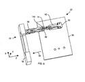
- Fig. 2A shows a perspective view of the latching apparatus 40 used by the connectors 28, 34 of the connection system 20.
- the latching apparatus 40 On the daughter card side (i.e., on the side of the connector 28, also see Figs. 1A and 1B), the latching apparatus 40 includes a guide member 50, a circuit board attachment member 52, and a control assembly 54 which integrates with the guide member 50.
- the latching apparatus 40 On the backplane side (i.e., on the side of the connector 34, also see Figs. 1A and 1B), the latching apparatus 40 includes a receptacle member 56.
- the circuit board attachment member 52 is configured to attach to the circuit board 26 of the daughter card 22.
- the receptacle member 56 is configured to attach to the circuit board 32 of the backplane 24.
- the guide member 50 is configured to (i) slidably engage with the circuit board attachment member 52 and (ii) selectively engage and disengage with the receptacle member 56. Accordingly, when the circuit board attachment member 52 is attached to the circuit board 26 of the daughter card 22 and when the receptacle member 56 is attached to the circuit board 32 of the backplane 24 as shown in Fig. 2A, the guide member 50 can latch the daughter card 22 to the backplane 24 by engaging and locking with the receptacle member 56. Such engaging and locking occurs when the guide member 50 is initially loaded through a cavity 58 defined by the circuit board attachment member 52, and then moved along the Z-axis in the direction 62 toward an opening 60 defined by the receptacle member 56 (see Fig. 2A).
- Fig. 2B shows the guide member 50 engaged with and locked to the receptacle member 56. Accordingly, the daughter card 22 is now considered latched to the backplane 24. In this situation, the guide member 50 is held rigidly by the receptacle member 56. Accordingly, any connecting elements rigidly attached to the guide member 50 and to the receptacle member 56 can connect in a robust and healthy manner. However, the guide member 50 is only loosely connected to the circuit board attachment member 52 in that there is substantial Z-direction freedom of movement available. As a result, there is minimal stress (if any) transferred from the latching apparatus 40 to the circuit boards 26, 32 that could otherwise jeopardize other connecting components (e.g., the solder joints of the electrical connectors 30, 36 in Fig. 1B) or that could fatigue or crack circuit board traces, etc.
- other connecting components e.g., the solder joints of the electrical connectors 30, 36 in Fig. 1B
- control assembly 54 which works in conjunction with the circuit board attachment member 52 and the receptacle member 56.
- control assembly 54 is configured to retain the circuit board attachment member 54 within a retaining range 64 of the guide member 50 when the guide member 50 is unlocked from the receptacle member 56. Such retention prevents the guide member 50 from inadvertently escaping from the circuit board attachment member 52 prior to latching and during the latching process.
- control assembly 54 is further configured to un-restrict the circuit board attachment member 52 such that the circuit board attachment member 52 is movable outside of the retaining range 64 of the guide member 50 (i.e., is movable to a location 66 outside the retaining range 64) when the guide member 50 is locked with the receptacle member 56. It is this operation that provides more freedom of movement along the Z-axis than was available prior to latching. Accordingly, after latching process is complete, there are less board stresses, if any, generated by the latching of the connectors 28, 34.
- the latch apparatus 40 is well-suited for connecting a circuit board which forms both fiber optic connections and electrical connections with another circuit board, e.g., see the daughter card 22 and the backplane 24 of Figs. 1A and 1B.
- the freedom of movement in the Z-direction allows the circuit boards to overcome issues relating to electrical wipe (e.g., relatively high amounts of mating forces required to establish electrical connections).
- such freedom of movement enables a staggered mating sequence (e.g., connection of fiber optic connectors first, then connection of electrical connectors) so that the connectors work in harmony rather than compete with each other.
- initial movement of the daughter card 22 toward the backplane 24 results in latching of the latch apparatus 40 of the fiber optic connectors 28, 34, i.e., locking the fiber optic connector 28 with the fiber optic connector 34 to for a set of robust fiber optic connections 42, and (ii) provides substantial freedom of movement in the Z-direction.
- Further movement of the daughter card 22 toward the backplane 24 results in engagement of the electrical connectors 30, 36 to form a healthy set of electrical connections 44. As the electrical connectors 30, 36 connect with each other (e.g., under 150 to 200 lbs.
- Fig. 3 shows an exploded view of a portion 70 of the latching apparatus 40.
- the portion 70 includes the guide member 50 and the control assembly 54.
- the control assembly 54 includes a retaining range control arm 72, a receptacle locking control arm 74, a pivot member 76, and a multi-spring member 78 and springs 80-A, 80-B (collectively, springs 80).
- the retaining range control arm 72 includes a wedge-shaped tab 82 and another wedge-shaped tab 84.
- the receptacle locking control arm 74 includes a wedge-shaped tab 86 and another wedge-shaped tab 88.
- Each wedge-shaped tab 82, 84, 86 and 88 includes an inner face 90 and an exterior face 92 (e.g., see the tab 84).
- the multi-spring member 78 includes a retaining range control arm spring 94 for biasing the retaining range control arm 72, and a receptacle locking control arm spring 96 for biasing the receptacle locking control arm 74.
- Fig. 4A shows a first angled view of the control assembly 54 assembled onto the guide member 50.
- Fig. 4B shows a second angled view of the control assembly 54 assembled onto the guide member 50 (i.e., a view from the other side of that shown in Fig. 4A).
- the pivot member 76 e.g., a guide pin which inserts through holes in the guide member 50
- the pivot member 76 pivotally couples the retaining range control arm 72 and the receptacle locking control arm 74 to the guide member 50. That is, the arms 72, 74 share the same pivot axis 98 as defined by the pivot member 76.
- the retaining range control arm 72 is configured to retain the circuit board attachment member 52 (also see Figs. 2A and 2B) within the retaining range 64 of the guide member 50 when the retaining range control arm 72 is in a first pivoted retaining range control arm orientation relative to the guide member 50.
- the retaining range control arm 72 is configured to un-restrict the circuit board attachment member 52 such that the circuit board attachment member 52 is movable outside of the retaining range 64 of the guide member 50 (i.e., is movable within a larger range 66 which overlaps and extends along the Z-axis beyond the retaining range 64) when the retaining range control arm 72 is in a second pivoted retaining range control arm orientation that is different than the first pivoted retaining range control arm orientation.
- the guide member 50 includes a base portion 100 which, as will be explained and shown in further detail later, is configured to modularly fit into any of multiple module positions of a holder of a connecting device.
- the guide member 50 further includes a blade-shaped portion 102 which is integral with the base portion 100.
- the blade-shaped portion 102 is configured to slide into a blade-shaped aperture defined by the receptacle member 52 (see the cavity 58 in Fig. 2A).
- the springs 80 mount to the base portion 100 of the guide member 50.
- the springs 80 bias the circuit board attachment member 52 from a location 104 within the retaining range 64 toward a location 106 within the retaining range 64 and away from the base portion 100. Further details of the invention will now be provided with reference to Figs. 5A and 5B.
- Fig. 5A shows a first angled view of the circuit board attachment member 52
- Fig. 5B shows a second angled view (i.e., from the other side of that show in Fig. 5B).
- the circuit board attachment member 52 includes a slide portion 110 and a set of protrusions 114-A, 114-B, 114-C (collectively, protrusions 114).
- the set of protrusions 114 are integral with the slide portion 110, and are configured to insert into holes of the daughter card circuit board 26.
- a user can then easily fasten the circuit board attachment member 52 to the circuit board 26 (e.g., by adding screws into the protrusions 114 through the opposite end of the circuit board 26, by affixing an attachment into the circuit board holes, etc.).
- the slide portion 110 defines the cavity 58 (also see Fig. 2A) through which the guide member 50 slides.
- the blade portion 102 of the guide member 50 which defines the large range 66 is substantially I-shaped. That is, that portion 102 defines a vertical portion 120 which is terminated by two horizontal portions 122-A, 122-B (collectively, horizontal portions 122).
- the vertical portion 120 of the guide member 50 fits through a vertical portion 124 (i.e., a volume or space) of the cavity 58, and the horizontal portions 122-A, 122-B of the guide member 50 fits through horizontal portions 126-A, 126-B of the cavity 58.
- the slide portion 110 of the circuit board attachment member 52 further defines a tab 130 for actuating the retaining range control arm 72 of the control assembly 54, and a tab 132 for actuating the receptacle locking control arm 74 of the control assembly 54.
- the tab 130 defines a ramp 134 (Fig. 5B) and a back 136.
- the ramp 134 is configured to move the retaining range control arm 72 from a first orientation (put in the first orientation due to biasing from the spring 94, see Fig. 4) to a second orientation (due to actuation of the arm 72 against the ramp 134).
- the tab 132 defines a ramp 138 and a back 139.
- the ramp 138 is configured to move the receptacle locking control arm 74 from a first orientation (put in the first orientation due to biasing from the spring 96, see Fig. 4) to a second orientation (due to actuation of the arm 74 against the ramp 138).
- the tabs 130, 132 are staggered relative to each other so that, as the guide member 50 slides further into the circuit board attachment member 52, the retaining range control arm 72 first actuates to lock the circuit board attachment member 52 within the retaining range 64 of the guide member 50. That is, the ramp 134 of the tab 130 moves the arm 72 from the first orientation to the second orientation to allow the circuit board attachment member 52 to move from a location outside the retaining range 64 into the retaining range 64. The tab 130 then moves past the arm 72 enabling the spring 94 to again bias the arm 72 back to the first orientation putting the back 136 of the tab 130 and an exterior face of the tab 82 of the arm 72 in direct contact. At this point, the back 136 of the tab 130 interferes with the exterior face of the arm 72 thus preventing the circuit board attachment member 52 from moving out of the retaining range 64.
- the ramp 138 of the tab 132 will eventually move the arm 74 from a first orientation to a second orientation. As will be explained shortly, this operation enables the arm 74 to unlock from the receptacle member 56. Further details of the invention will now be provided with reference to Figs. 6A and 6B.
- Fig. 6A shows an exploded view of the receptacle member 56 (also see Figs. 2A and 2B).
- the receptacle member 56 includes side members 140-A, 140-B (collectively, side members 140), a circuit board attachment member 142, and hardware 144-A, 144-B, 144-C, 144-D, 144-E and 144-F (collectively, hardware 144) for holding the side members 140 together and thus retaining the circuit board attachment member 142 in a fixed position.
- the circuit board attachment member 142 includes a base portion 145 for engaging with the side members 140, and a set of protrusions 147 for attaching to the circuit board 32 of the backplane 24 (also see Figs. 1A and 1B).
- the set of protrusions 147 form a unitary member with the base portion 145, and are configured to insert into holes of the backplane circuit board 32.
- a user can then easily fasten the circuit board attachment member 142 (and the receptacle member 56 as a whole) to the backplane circuit board 32 (e.g., by adding screws into the protrusions 147 through the opposite end of the circuit board 32, by affixing an attachment into the circuit board holes using glue, etc.).
- the base portion 145 of the circuit board attachment member 142 includes posts that prevent the side members 140-A, 140-B from major rotation but allow minor or limited rotation (i.e., a circular range of freedom) allowing for true-positional placement in the X and Y direction.
- This freedom of movement in the X-Y plane reduces the likelihood of transferring stresses (e.g., X-Y displacement stresses, torques and angular stresses, twisting stresses, etc.) from the latching apparatus 40 to the circuit boards 26, 32 (e.g., due to a buildup of tolerances).
- stresses e.g., X-Y displacement stresses, torques and angular stresses, twisting stresses, etc.
- Fig. 6B shows a side of the side member 140-B which is opposite that shown in Fig. 6A.
- the side member 140-B is identical to the side member 140-A.
- This feature of the invention enables the manufacturer to minimize costs by making only one type of side member for use as sides of the receptacle member 56 rather than two types.
- the entire receptacle member 56 is made as a singularly-formed, unitary member, i.e., one part.
- the side members 140 define (in addition to the opening 60, see Fig. 2A) a tab 146 having a ramp 148 and a back 150, and another tab 152 defining a surface 154.
- the ramp 148 of the tab 146 actuates the receptacle locking control arm 74 of the control assembly 54 by moving the arm 74 from a first orientation to a second orientation. Once the tab 146 passes the arm 74, the arm 74 returns to the first orientation due to biasing from the spring 96 (also see Fig. 3). As will be explained shortly, this operation enables the control assembly 54 to lock the guide member 50 to the receptacle member 56.
- the latching apparatus 40 enables the daughter card 22 to selectively latch with and unlatch from the backplane 24.
- This latching and de-latching operation is controllable by simply moving the daughter card 22 relative to the backplane 24. That it, there is no need for a user to directly manipulate particular portions of the latching apparatus 40. Rather, the user can simply move the daughter card 22 (to which the circuit board attachment member 52 attaches) relative to the backplane 24 (to which the circuit board attachment member 142 attaches).
- This operation is referred to as "blind mating" and is well-suited for applications in which a user cannot or has difficulty directly accessing connectors.
- the user can simply move the circuit boards relative to each other (e.g., move the daughter card 22 relative to the backplane 24) to latch and unlatch connectors.
- the backplane 24 resides at the back of a card cage assembly, and that the daughter card 22 slides into the card cage assembly and against the backplane 24.
- a user cannot directly access the vicinity of the backplane 24 inside the card cage assembly when the daughter card 22 is present.
- the user can simply push and pull on the daughter card 22 to move the daughter card 22 relative to the backplane 24 in order to connect the daughter card 22 to, and disconnect the daughter card 22 from, the backplane 24 due to the blind mating features provided by the latching apparatus 40.
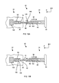
- Figs. 7A and 7B show cross-sectional views from a bottom angle of the latching apparatus 40 through dissecting lines A-A and B-B of Fig. 2A, respectively, at an initial point in time during the latching process.
- the line A-A cuts through the receptacle locking control arm 74
- the line B-B cuts through the retaining range control arm 72.
- the receptacle locking control arm 74 is biased in the counter clockwise direction by the spring 96 (Fig. 3) which is omitted from Fig. 7A for simplicity.
- the retaining range control arm 72 is biased in the counter clockwise direction by the spring 94 (Fig. 3) which is omitted from Fig. 7B for simplicity.
- the circuit board 26 of the daughter card 22 moves toward the circuit board 32 of the backplane 24 in the direction of the arrow 38 (also see Fig. 1A).
- the circuit board attachment member 52 which is fastened to the daughter card circuit board 26, moves the guide member 50 toward the receptacle member 56. That is, as shown in Fig. 7B, the back 136 of the tab 130 of the circuit board attachment member 52 pushes the tab 82 of the retaining range control arm 72 (also see Fig. 3) so that the blade portion 102 of the guide member 50 moves toward the opening 60 defined by the receptacle member 56 and so that the circuit board attachment member 52 is maintained within the retaining range 64 of the guide member 50 (also see Fig. 4A).
- Figs. 8A and 8B respectively show cross-sectional views from the bottom angle of the latching apparatus 40 through dissecting lines A-A and B-B of Fig. 2A at a next point in time during the latching process.
- Fig. 8A shows that the tab 88 receptacle locking control arm 74 begins to make contact with the ramp 148 of the tab 146 defined by the receptacle member 56 (also see Figs. 6A and 6B).
- the back 136 of the tab 130 of the circuit board attachment member 52 continues to push the tab 82 of the retaining range control arm 72 thus moving the guide member 50 into the receptacle member 56.
- Fig. 9 shows a cutaway view (from a top angle) of the latching apparatus 40 as the guide member 50 inserts into the receptacle member 56.
- the ramped exterior surface of the tab 88 of the receptacle locking control arm 74 makes contact with the tab 146 of the receptacle member 56 as the guide member 50 continues to move forward along the Z-axis (i.e., in the negative Z-direction 38).
- Figs. 10A and 10B respectively show cross-sectional views from a bottom angle of the latching apparatus 40 through dissecting lines A-A and B-B of Fig. 2A at yet a next point in time during the latching process.
- Fig. 10A shows that the receptacle locking control arm 74 has moved in the clockwise direction (from the perspective of Fig. 10A) from a first biased orientation (Figs. 7A and 8A) to a second orientation allowing the tab 88 of the receptacle locking control arm 74 to just clear the tab 146 of the receptacle member 56.
- Such movement must overcome the biasing forces of the receptacle locking control arm spring 96 (Fig.
- Figs. 11A and 11B respectively show cross-sectional views from the bottom angle of the latching apparatus 40 through dissecting lines A-A and B-B of Fig. 2A at another point in time during the latching process.
- the receptacle locking control arm 74 has moved back in the counterclockwise direction to the first orientation due to biasing from the spring 96 so that the inner face of the tab 88 now prevents the guide member 50 from moving in the direction opposite the arrow 38.
- Fig. 11A and 11B respectively show cross-sectional views from the bottom angle of the latching apparatus 40 through dissecting lines A-A and B-B of Fig. 2A at another point in time during the latching process.
- the receptacle locking control arm 74 has moved back in the counterclockwise direction to the first orientation due to biasing from the spring 96 so that the inner face of the tab 88 now prevents the guide member 50 from moving in the direction opposite the arrow 38.
- Fig. 11A and 11B respectively show cross-sectional views
- FIG. 12A shows a cutaway view (from a top angle) of the receptacle locking control arm 74 at this point, i.e., as the tab 88 just moves past the back 150 of the tab 146 and the receptacle locking control arm 74 moves back to its first orientation.
- the back 136 of the tab 130 of the circuit board attachment member 52 continues to push the tab 82 of the retaining range control arm 72 and the tab 84 of the retaining range control arm 72 begins to make contact with the tab 152 of the receptacle member 56 (also see Fig. 6A and 6B).
- Fig. 12B shows cutaway view (from a top angle) of the receptacle locking control arm 74 at this point.
- Figs. 13A and 13B respectively show cross-sectional views from the bottom angle of the latching apparatus 40 through dissecting lines A-A and B-B of Fig. 2A at a further point in time during the latching process.
- the receptacle locking control arm 74 remains in the first orientation due to biasing from the spring 96 so that the guide member 50 is latched within the receptacle member 56.
- interference from the tab 152 has moved the retaining range control arm 72 in the clockwise direction (from the perspective of Fig. 13B) from an initial biased orientation (Figs.
- Figs. 14A and 14B respectively show cross-sectional views from the bottom angle of the latching apparatus 40 through dissecting lines A-A and B-B of Fig. 2A at yet another point in time during the latching process.
- the circuit board attachment member 52 is at the end of travel in the float range 64. Latching is compete, i.e. loads are contained, when the tab 82 of the arm 72 has ramped over the tab 130 and the load is carried through the arm 74 at the interface between the tab 88 of the arm 74 and the tab 146 of the receptacle member 56.
- the receptacle locking control arm 74 continues to remain in the first orientation due to biasing from the spring 96 so that the guide member 50 remains locked within the receptacle member 56.
- the tab 82 of the retaining range control arm 72 has cleared the tab 130 of the circuit board attachment member 52.
- This situation is further illustrated in a top angle view of Fig. 15.
- the retaining range control arm 72 has moved back in the counterclockwise direction to the first orientation due to biasing from the spring 94. Accordingly, the arm 72 of the control assembly 54 no longer holds the circuit board attachment member 52 within the retaining range 64 of the guide member 50 and the circuit board attachment member 52 is now free to travel outside the retaining range 64.
- any connector pieces attached to the guide member 50 and the receptacle member 56 can connect in a healthy and robust manner. Contact forces and stresses between these elements and between the guide member 50 and the receptacle member 56 are not transferred to the circuit boards 26, 32 due to the Z-directional float provided by the latching apparatus 40. Rather, the stresses are isolated between the guide member 50, the receptacle member 56 and the associated connecting elements, and not transmitted to the circuit boards 26, 32.
- latching occurs without direct manipulation of the latching components. Rather, such latching occurs in response to movement of the circuit board 26 relative to the circuit board 32 in a blind mating manner. Such movement is available in card cage assembly applications and other applications in which the user cannot or does not wish to access the latching components directly (e.g., where the user simply pushes the daughter card circuit board 26 toward the backplane circuit board 32).
- the daughter card circuit board 26 is preferably held in a fixed position relative to the backplane circuit board 32.
- the daughter card circuit board 26 can include levers which engage with a card cage assembly to prevent the daughter card circuit board 26 from inadvertently moving away from the backplane circuit board 36 due to vibration.
- the latching apparatus 40 unlocks when the daughter card 22 moves in the positive Z-direction (i.e., the direction opposite the arrow 38 in Figs. 14A, 14B and 15. Such de-latching can occur when a user pulls the daughter card 22 out of a card cage assembly and away from the backplane 24 in a blind de-mating manner.
- Fig. 16 shows a cross-sectional view from the bottom angle of the latching apparatus 40 through the dissecting line B-B of Fig. 2A as the daughter card 22 moves in the positive Z-direction, i.e., in the direction of the arrow 160.
- the guide member 50 is held in place relative to the receptacle member 56 due to engagement of the receptacle locking control arm 74 with the tab 146 (see Fig. 14A).
- the tab 130 of the circuit board attachment member 52 moves in the direction 160 with the daughter card 22 and actuates the retaining range control arm 72 in the clockwise direction. That is, the ramp 134 of the tab 130 (Fig.
- Fig. 17 shows a cross-sectional view from the bottom angle of the latching apparatus 40 through the dissecting line A-A of Fig. 2A as the daughter card 22 continues to move in the positive Z-direction 160.
- the circuit board attachment member 52 compresses the springs 80 (Fig. 3) and moves very close to the base portion 100 of the guide member 50.
- the circuit board attachment member 52 moves from the location 106 to the location 104 within the retaining range 64 (see Figs. 4A and 4B).
- the tab 132 of the circuit board attachment member 52 actuates the receptacle locking control arm 74.
- the ramp 138 of the tab 132 (Fig.
- the arm 74 Once the arm 74 is moved to the second orientation and the guide member 50 unlatches from the receptacle member 56, the springs 80 and 94 and decompress. Accordingly, the arm 74 moves back to its first orientation due to biasing from the spring 94, and the daughter card circuit board 26 can be moved so that the blade portion 102 of the guide member 50 completely exits the receptacle member 56 (see Figs. 7A and 7B).
- the daughter card 22 is completely disconnected from the backplane 24. Additionally, the latching apparatus 40 is reloaded (i.e., the guide member 50 is securely retained in the retaining range 64 and is ready for a subsequent latching operation.
- the daughter card 22 and the backplane 24 can connect and disconnect again and again as described above. Moreover, such connecting and disconnecting can occur in a blind mating and blind un-mating manner simply by moving the daughter card 22 and the backplane 24 relative to each other without directly manipulating the latching apparatus 40.
- the latching apparatus 40 is well-suited as a latching mechanism for connectors.
- the latching apparatus 40 can be tailored to fit one of any modularized locations in a connector that holds multiple connecting elements together. Such modularization enables easy scalability with little or no retooling and/or redesigning.
- Fig. 18 shows a fiber optic connector 200 which utilizes the latching apparatus 40.
- the fiber optic connector 200 includes a support 202, a set of spring-loaded fiber optic connecting elements 204-A, 204-B, 204-C (collectively, connecting elements 204), and a set of latching elements 206-A, 206-B (collectively, latching elements 206).
- Fiber optic cables 208 of the connecting elements 204 extend from ends 210 of the connecting elements 204 which are opposite fiber optic interface ends 212 of the connecting elements 204.
- the connector 200 includes three fiber optic connecting elements 204 which are arranged in a row, i.e., in a side-by-side manner.
- the latching elements 204 are disposed on each end of the row of connecting elements 204.
- Other arrangements include a different number of connecting elements 204.
- other arrangements include at least one latching element 206 which is not at an end of a row connecting elements 204.
- any of the connecting elements 204 can be replaced with a latching element 206.
- the support 202 can be extended (or shortened) to hold a different number of connecting elements 204 and/or a different number of latching elements 206.
- latching elements 206 enable forces to be distributed among the latching elements 206. Accordingly, less force is placed on any particular latching element 206.
- the support 202 includes a substantially rigid material such as metal or plastic, and is made available different lengths to accommodate different numbers of elements (e.g., five, six, seven, etc.).
- the support 202 be made from a U-shaped length of steel which is simply cut to a particular length. Accordingly, different combinations of elements 204, 206 can be put together for different custom applications without retooling and redesigning a multitude of housings as is done in the conventional floating housing approach. Thus, there is significant cost savings available to the manufacturer.
- the connector 200 is suitable for use as the connector 28 of the daughter card 22 (also see Figs. 1A and 1B).
- the connector 200 is configured to connect with a corresponding connector having corresponding receptacle members (see the receptacle member 56 of Figs. 6A and 6B) to receive the latching elements 206.
- the latching elements 206 lock with the receptacle members to hold the fiber optic connecting elements 204 against corresponding fiber optic connecting elements of the corresponding connector to form a set of healthy and robust fiber optic connections.
- Such locking can occur in a blind mating operation where the latching elements 206 of the connector 200 are retained in retaining ranges 64 of circuit board attachment members 52 of the circuit board.
- the circuit board attachment members 52 are freed from the retaining ranges 64 to provide substantial freedom of movement in the Z-direction to minimize or completely avoid transfer of connector stresses to circuit boards.
- connecting elements 204 and the latching elements 206 enables easy removal and repair of a particular element 204, 206. That is, if there is damage to a particular element 204, 206, only that element 204, 206 need be removed and replaced rather than the entire connector 200.
- a manufacturer develops a new design for an element 204, 206 (i.e., a new connecting element 204, a new latching element 206 or yet another element, etc.)
- the manufacturer can easily integrate that new design by including it in one or more module locations within the connector 200.
- the manufacturer does not need to significantly retool the entire connector (e.g., redesign the entire connector housing, etc.).
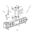
- Fig. 19 shows a connector 220 similar to the connector 200 of Fig. 18 installed on a circuit board 222 (e.g., the daughter card circuit board 22 of Figs. 1A and 1B). Circuit board components 224 are mounted on the circuit board 222 as well.
- the connector 220 includes a support 226 for carrying seven modularized elements 204, 206, and hardware 228 for securing the latching elements 206 in place.
- the connector 220 includes five connecting elements 204 which are interleaved between three latching elements 206. The multiple latching elements 206 facilitate distribution of forces so that no particular latching element 206 bears the entire amount of force.
- the circuit board attachment members 52 have slide portions 110 (also see Figs. 5A and 5B) having a thickness which raise the height of the support 226 and the connecting elements 204, 206 to allow one or more circuit board components 224 to reside between the surface of the circuit board 222 and the connecting elements 204, 206. That is, the circuit board attachment members 52 provide clearance between the connecting elements 204, 206 (e.g., the guide members 50) and circuit board components 224 mounted on the circuit board 222 when the circuit board attachment members 52 attach to the circuit board 222.
- Fig. 19 shows a circuit board component 224-X disposed between the circuit board 222 and the support 226. Such arrangements reduce the amount of surface area of the circuit board 222 required by the connector 220 thus freeing board space for other components. Further details of the invention will now be provided with reference to Fig. 20.
- Fig. 20 shows a procedure 240 performed by a user of the latching apparatus 40 when operating the latching apparatus 40.
- the operation of the latching apparatus 40 will be further described with reference to the connector 200 of Fig. 18, and the daughter card 22 and the backplane 24 of Figs. 1A and 1B.
- step 242 the user retains the circuit board attachment member 52 within the retaining range 64 of the guide member 50.
- the user takes the connector 200 of Fig. 18 and installs the connector 200 on the daughter card circuit board 26 by inserting the guide members 50 of the latching elements 206 through circuit board attachment members 52 secured to the daughter card circuit board 26.
- step 244 the user engages the guide member 50 within the receptacle member attached to the backplane circuit board 32.
- the user moves the daughter card 22 toward the backplane 24 such that the guide members 50 of the latching elements 206 engage with corresponding receptacle members 56 on a corresponding backplane connector.
- step 246 the user un-restricts the circuit board attachment member 52 such that the circuit board attachment member 52 is movable outside of the retaining range 64 of the guide member 50 when the guide member 50 is locked with the receptacle member 56.
- the user further moves the daughter card 22 toward the backplane 24 until the guide members 50 of the connector 200 latch to respective receptacle members 56 of a corresponding backplane connector.
- the circuit board attachment members 52 are no longer retaining within the retaining ranges 64 of the guide members 50.
- the connector 200 has substantial freedom of movement in the Z-direction to avoid passing on connector stresses (e.g., stresses due to poor tolerances) to the daughter card 22 and the backplane 24 (e.g., to solder joints of electrical components).
- Such connection can be made in response to blind mating operation (i.e., simply moving the daughter card 22 and the backplane 24 together such as by pushing the daughter card 22 toward the backplane 24 in a card cage assembly).
- step 248 the user can disconnect the daughter card 22 from the backplane 24 by moving the circuit board attachment member 52 back into the retaining range 64, and then from the location 106 to the location 104 within the retaining range 64 thus re-retaining the circuit board attachment member 52 within the guide member 50 and unlocking the guide member 50 from the receptacle member 56.
- the user simply pulls the daughter card 22 away from the backplane 24.
- the control assemblies 54 actuate to re-retain the circuit board attachment members 52 within the latching elements 206, and to unlock the guide members 50 from the receptacle members 56 of the corresponding backplane connector. Again, such de-latching can occur in response to a blind de-mating operation by simply pulling the daughter card 22 away from the backplane 24.
- the fiber optic connectors 28, 34 and the electrical connectors 30, 36 can be configured to connect in a staggered manner such that they work together in harmony rather than compete against each other.
- the fiber optic connectors 28, 34 function as butt-coupled devices. That is, the end faces must remain in physical contact at all times to insure that the optical signal is stable and uninterrupted. Fortunately, this does not complicate matters since the optical mating sequence can be established prior to the electrical.
- the freedom of movement along the Z-axis enables compatibility and limits the possibility of conjoined future force spikes.
- freedom of movement within a relatively large range e.g., 3 to 7 mm
- a slideable mechanism i.e., the guide member 50 slidably engaged within the circuit board attachment member 52.
- the staggered mating sequence can occur transparently to the user. That is, the latching, when sequenced correctly, can provide a blind-mate coupling between the daughter card 22 and the backplane 24. The user can be made unaware of the latching or disengagement process. Once mated, any forces generated against the backplane 24 are then relaxed by means of the floating (slideable) members (i.e., the guide members 50 sliding within the circuit board attachment members 52 outside their retaining range 64. This prevents the potential for cracking traces or deforming the backplane over time and temperature.
- the floating (slideable) members i.e., the guide members 50 sliding within the circuit board attachment members 52 outside their retaining range 64. This prevents the potential for cracking traces or deforming the backplane over time and temperature.
- the invention is directed to techniques for connecting elements together (e.g., fiber optic interface elements) using an improved latching apparatus 40.
- the latching apparatus 40 employs a control assembly 54 (e.g., an assemblage of control arms 72, 74) which operates to connect the elements in a manner that permits substantial connector movement in the Z-direction, as well as enables easy scalability and customization with minimal or no retooling.
- a control assembly 54 e.g., an assemblage of control arms 72, 74
- With substantial Z-directional movement available there is little or no Z-directional board stress transmitted from connectors to other locations (e.g., to electrical connectors having fragile solder joints).
- Such easy scalability enables a manufacturer to offer a variety of connector configurations without incurring significant retooling and redesigning costs.
- the latching apparatus 40 was described above as being suitable for connecting fiber optic connecting elements 204 by way of example.
- the latching apparatus 40 is also suitable for connecting other types of connecting elements as well such as electrical connecting elements (e.g., elements with electrical contacts, pads, feet, pins, etc).
- the latching apparatus 40 provides mechanical latching for multiple devices (e.g., circuit board to circuit board, circuit board component to circuit board component, etc.).
- the latching apparatus 40 is useful in applications which involve connecting multiple parts together, and can be scaled larger or smaller than that described above for forming fiber optic connections.
- the latching apparatus 40 was described above as being well-suited for latching a daughter card circuit board 26 moving along the Z-axis relative to a backplane circuit board 32 by way of example only.
- the latching apparatus 40 is suitable for latching in other orientations as well such as in latching together two circuit boards disposed in a parallel manner where the Z-direction is substantially perpendicular to the planes of the circuit boards.
- the guide members 50 are not necessarily drawn to scale.
- the guide members 50 are taller, and well-suited for connectors having taller connecting elements 204 (e.g., connecting elements having multiple ferrules or tall ferrules for higher density applications).
- the latching apparatus 40 was described above as latching circuit boards together by way of example only.
- the latching apparatus 40 is well-suited for latching other devices as well such as a variety of devices having the form of a moving panel, a flat plate, and the like.
- the various components described above can be broadly construed in their operation.
- the above-described circuit board attachment member 52 when fastened to a general flat panel or plate (rather than a circuit board) is essentially a panel attachment member, and so on.
- the receptacle member 56 is modularized on the backplane side thus enabling corresponding backplane connectors (e.g., see the backplane connector 34) to include modular connecting and latching elements as well.
Landscapes
- Physics & Mathematics (AREA)
- General Physics & Mathematics (AREA)
- Optics & Photonics (AREA)
- Details Of Connecting Devices For Male And Female Coupling (AREA)
- Coupling Device And Connection With Printed Circuit (AREA)
- Mechanical Coupling Of Light Guides (AREA)
- Optical Communication System (AREA)
Claims (21)
- Dispositif de verrouillage comprenant :un élément de guidage (50) ;un élément de fixation de carte de circuit (52) qui est agencé pour se fixer à une carte de circuit (26) ; etune structure de commande (54) qui est agencée pour :maintenir l'élément de fixation de carte de circuit (52) à l'intérieur d'une plage de maintien de l'élément de guidage quand l'élément de guidage est déverrouillé d'un élément de réceptacle (56) ; etdébloquer l'élément de fixation de carte de circuit (52) de sorte que l'élément de fixation de carte de circuit est mobile en dehors de la plage de maintien de l'élément de guidage (50) quand l'élément de guidage est verrouillé avec l'élément de réceptacle.
- Dispositif de verrouillage selon la revendication 1, dans lequel la structure de commande comprend :un bras de commande de plage de maintien (72) qui est couplé à pivotement à l'élément de guidage (50), le bras de commande de plage de maintien étant agencé pour :(i) maintenir l'élément de fixation de carte de circuit dans la plage de maintien de l'élément de guidage quand le bras de commande de plage de maintien est dans une première orientation de rotation du bras de commande de plage de maintien par rapport à l'élément de guidage ; et(ii) débloquer l'élément de fixation de carte de circuit de sorte que l'élément de fixation de carte de circuit est mobile en dehors de la plage de maintien de l'élément de guidage quand le bras de commande de plage de maintien est dans une seconde orientation de rotation du bras de commande de plage de maintien qui est différente de la première orientation de rotation du bras de commande de plage de maintien.
- Dispositif de verrouillage selon la revendication 2, dans lequel la structure de commande comprend en outre :un bras de commande de verrouillage de réceptacle (74) qui est couplé à pivotement à l'élément de guidage, dans lequel le bras de commande de verrouillage de réceptacle est agencé pour :(i) verrouiller l'élément de guidage avec l'élément de réceptacle quand le bras de commande de verrouillage de réceptacle est dans une première orientation de rotation du bras de commande de verrouillage de réceptacle par rapport à l'élément de guidage ; et(ii) déverrouiller l'élément de guidage de l'élément de réceptacle quand le bras de commande de verrouillage de réceptacle est dans une seconde orientation de rotation du bras de commande de verrouillage de réceptacle qui est différente de la première orientation de rotation du bras de commande de verrouillage de réceptacle.
- Dispositif de verrouillage selon la revendication 3, dans lequel la structure de commande comprend en outre un élément de pivotement commun (76) couplé à l'élément de guidage, et dans lequel chacun du bras de commande de plage de maintien et du bras de commande de verrouillage de réceptacle est agencé pour pivoter autour de l'élément de pivotement commun.
- Dispositif de verrouillage selon la revendication 3, dans lequel la structure de commande comprend en outre :un ressort de bras de commande de plage de maintien (78) couplé à l'élément de guidage qui est agencé pour solliciter le bras de commande de plage de maintien dans la première orientation de rotation du bras de commande de plage de maintien par rapport à l'élément de guidage ; etun ressort de bras de commande de verrouillage de réceptacle couplé à l'élément de guidage agencé pour solliciter le bras de commande de verrouillage de réceptacle dans la première orientation de pivotement du bras de commande de verrouillage de réceptacle par rapport à l'élément de guidage.
- Dispositif de verrouillage selon la revendication 1, dans lequel la structure de commande comprend :un bras de commande de verrouillage de réceptacle (74) qui est couplé à pivotement à l'élément de guidage, le bras de commande de verrouillage de réceptacle étant agencé pour :(i) verrouiller l'élément de guidage avec l'élément de réceptacle quand le bras de commande de verrouillage de réceptacle est dans une première orientation de rotation du bras de commande de verrouillage de réceptacle par rapport à l'élément de guidage ; et(ii) déverrouiller l'élément de guidage de l'élément de réceptacle quand le bras de commande de verrouillage de réceptacle est dans une seconde orientation de rotation du bras de commande de verrouillage de réceptacle qui est différente de la première orientation de rotation du bras de commande de verrouillage de réceptacle.
- Dispositif de verrouillage selon la revendication 6, dans lequel l'élément de fixation de carte de circuit (52) est agencé pour déplacer le bras de commande de verrouillage de réceptacle de la première orientation de rotation du bras de commande de verrouillage de réceptacle vers la seconde orientation de rotation du bras de commande de verrouillage de réceptacle pour déverrouiller l'élément de guidage de l'élément de réceptacle quand l'élément de fixation de carte de circuit (52) se déplace d'un premier emplacement dans la plage de maintien de l'élément de guidage vers un second emplacement dans la plage de maintien de l'élément de guidage.
- Dispositif de verrouillage selon la revendication 7, comprenant en outre :un ressort couplé à l'élément de guidage pour solliciter l'élément de fixation de carte de circuit (52) depuis le second emplacement dans la plage de maintien de l'élément de guidage vers le premier emplacement dans la plage de maintien de l'élément de guidage.
- Dispositif de verrouillage selon la revendication 1, dans lequel l'élément de fixation de carte de circuit comprend une partie de glissement (110) qui couple l'élément de fixation de carte de circuit à l'élément de guidage de façon coulissante.
- Dispositif de verrouillage selon la revendication 9, dans lequel l'élément de fixation de carte de circuit comprend en outre un ensemble de saillies (114) d'une seule pièce avec la partie de glissement, dans lequel l'ensemble de saillies est agencé pour limiter le déplacement de l'élément de fixation de carte de circuit par rapport à la carte de circuit quand l'élément de fixation de carte de circuit se fixe à la carte de circuit.
- Dispositif de verrouillage selon la revendication 9, dans lequel l'élément de guidage (50) est agencé pour se verrouiller et se déverrouiller avec l'élément de réceptacle (56) dans la direction de l'axe Z, et dans lequel la partie de glissement de l'élément de fixation de carte de circuit (52) se couple à l'élément de guidage de sorte que l'élément de fixation de carte de circuit peut coulisser par rapport à l'élément de guidage dans la direction de l'axe Z tout en empêchant sensiblement un déplacement de l'élément de fixation de carte de circuit par rapport à l'élément de guidage dans les directions des axes X et Y.
- Dispositif de verrouillage selon la revendication 9, dans lequel la partie de glissement de l'élément de fixation de carte de circuit est agencée pour assurer un jeu entre l'élément de guidage et un composant de carte de circuit monté sur la carte de circuit quand l'élément de fixation de carte de circuit se fixe à la carte de circuit.
- Dispositif de verrouillage selon la revendication 1, dans lequel l'élément de guidage comprend :une partie de base qui est agencée pour se monter de façon modulaire à l'une quelconque de plusieurs positions d'un support d'un dispositif de connexion ; etune partie en forme de lame qui est d'une seule pièce avec la partie de base, la partie en forme de lame étant agencée pour coulisser dans une ouverture en forme de lame définie par l'élément de réceptacle.
- Connecteur (200) comprenant :un élément de connexion (204) ;un support (202) ; etun dispositif de verrouillage (206) couplé par le support à l'élément de connexion, le dispositif de verrouillage comprenant :un élément de guidage ;un élément de fixation de carte de circuit qui est agencé pour se fixer à une carte de circuit ; etune structure de commande qui est agencée pour :maintenir l'élément de fixation de carte de circuit à l'intérieur d'une plage de maintien de l'élément de guidage quand l'élément de guidage est déverrouillé d'un élément de réceptacle ; etdébloquer l'élément de fixation de carte de circuit de sorte que l'élément de fixation de carte de circuit est mobile en dehors de la plage de maintien de l'élément de guidage quand l'élément de guidage est verrouillé avec l'élément de réceptacle.
- Connecteur selon la revendication 14, dans lequel l'élément de connexion est un corps de connexion de fibre optique ayant une interface de fibre optique.
- Module de carte de circuit comprenant :une carte de circuit (222) ;un ensemble de composants de carte de circuit (224) montés sur la carte de circuit ; etun connecteur (220) comprenant (i) un élément de connexion en communication avec l'ensemble de composants de carte de circuit, (ii) un support, et (iii) un dispositif de verrouillage couplé par le support à l'élément de connexion, le dispositif de verrouillage (206) comprenant :un élément de guidage ;un élément de fixation de carte de circuit qui est agencé pour se fixer à une carte de circuit ; etune structure de commande qui est agencée pour :maintenir l'élément de fixation de carte de circuit à l'intérieur d'une plage de maintien de l'élément de guidage quand l'élément de guidage est déverrouillé d'un élément de réceptacle ; etdébloquer l'élément de fixation de carte de circuit de sorte que l'élément de fixation de carte de circuit est mobile en dehors de la plage de maintien de l'élément de guidage quand l'élément de guidage est verrouillé avec l'élément de réceptacle.
- Module selon la revendication 16, dans lequel l'ensemble de composants de carte de circuit inclut un composant de fibre optique et dans lequel l'élément de connexion du connecteur est un corps de connexion de fibre optique ayant une interface de fibre optique qui est en communication avec le composant de fibre optique.
- Module de carte de circuit comprenant :un premier réceptacle pour recevoir un élément de guidage, le premier réceptacle étant adapté à recevoir un mécanisme de montage flottant pour fixation à un premier dispositif plan ;un second réceptacle pour porter un élément de guidage coulissant, le réceptacle étant adapté à un mécanisme de montage fixe pour fixation à un second dispositif plan ;un élément de guidage couplé à coulissement au second réceptacle et dans celui-ci pour fixation au premier réceptacle ;un premier mécanisme de maintien prévu entre le second réceptacle et l'élément de guidage, pour engager l'élément de guidage avec le second réceptacle quand l'élément de guidage n'est pas couplé au premier réceptacle ;un second mécanisme de maintien prévu entre le premier réceptacle et l'élément de guidage, pour engager l'élément de guidage avec le premier réceptacle tandis que le second réceptacle est encore couplé à l'élément de guidage ;un premier mécanisme de séparation prévu entre le premier réceptacle et l'élément de guidage pour séparer le premier mécanisme de maintien du second réceptacle quand l'élément de guidage est maintenu dans le premier réceptacle au moyen du second mécanisme de maintien ; etun second mécanisme de séparation prévu entre le second réceptacle et l'élément de guidage pour séparer le second mécanisme de maintien quand le second réceptacle a été recouplé à l'élément de guidage et que le premier réceptacle est découplé de l'élément de guidage.
- Système de connexion comprenant :un premier connecteur coportant un premier élément de connexion et un élément de réceptacle ;un second connecteur comportant (i) un second élément de connexion, (ii) un support, et (iii) un dispositif de verrouillage couplé par le support au second élément de connexion, le dispositif de verrouillage comprenant :un élément de guidage (50) ;un élément de fixation de carte de circuit (52) qui est agencé pour se fixer à une carte de circuit ; etune structure de commande (54) qui est agencée pour :maintenir l'élément de fixation de carte de circuit à l'intérieur d'une plage de maintien de l'élément de guidage quand l'élément de guidage est déverrouillé de l'élément de réceptacle du premier connecteur ; etdébloquer l'élément de fixation de carte de circuit de sorte que l'élément de fixation de carte de circuit est mobile en dehors de la plage de maintien de l'élément de guidage quand l'élément de guidage est verrouillé avec l'élément de réceptacle du premier connecteur de sorte que les premier et second éléments de connexion sont connectés l'un à l'autre.
- Procédé de connexion d'un premier module de carte de circuit à un second module de carte de circuit en utilisant un dispositif de verrouillage comportant (i) un élément de guidage, et (ii) un élément à conductivité variable fixé à une carte de circuit du premier module de carte de circuit, le procédé comprenant les étapes suivantes :maintenir l'élément de fixation de carte de circuit dans une plage de maintien de l'élément de guidage ;engager l'élément de guidage dans un élément de réceptacle fixé à la carte de circuit du second module de carte de circuit ; etdébloquer l'élément de fixation de carte de circuit de sorte que l'élément de fixation de carte de circuit est mobile en dehors de la plage de maintien de l'élément de guidage quand l'élément de guidage est verrouillé avec l'élément de réceptacle.
- Procédé selon la revendication 20, comprenant en outre l'étape consistant à déplacer l'élément de fixation de carte de circuit d'un premier emplacement dans la plage de maintien de l'élément de guidage vers un second emplacement dans la plage de maintien de l'élément de guidage pour remaintenir l'élément de fixation de carte de circuit dans la plage de maintien de l'élément de guidage et pour déverrouiller l'élément de guidage de l'élément de réceptacle.
Applications Claiming Priority (3)
| Application Number | Priority Date | Filing Date | Title |
|---|---|---|---|
| US10/195,288 US6762941B2 (en) | 2002-07-15 | 2002-07-15 | Techniques for connecting a set of connecting elements using an improved latching apparatus |
| US195288 | 2002-07-15 | ||
| PCT/US2003/021914 WO2004008578A1 (fr) | 2002-07-15 | 2003-07-15 | Techniques pour connecter un ensemble d'elements connecteurs au moyen d'un dispositif de verrouillage ameliore |
Publications (2)
| Publication Number | Publication Date |
|---|---|
| EP1537629A1 EP1537629A1 (fr) | 2005-06-08 |
| EP1537629B1 true EP1537629B1 (fr) | 2007-01-10 |
Family
ID=30114951
Family Applications (1)
| Application Number | Title | Priority Date | Filing Date |
|---|---|---|---|
| EP03764595A Expired - Lifetime EP1537629B1 (fr) | 2002-07-15 | 2003-07-15 | Techniques pour connecter un ensemble d'elements connecteurs au moyen d'un dispositif de verrouillage ameliore |
Country Status (8)
| Country | Link |
|---|---|
| US (1) | US6762941B2 (fr) |
| EP (1) | EP1537629B1 (fr) |
| JP (1) | JP2005533281A (fr) |
| CN (1) | CN1682409B (fr) |
| AU (1) | AU2003249207A1 (fr) |
| CA (1) | CA2492650A1 (fr) |
| DE (1) | DE60311111T2 (fr) |
| WO (1) | WO2004008578A1 (fr) |
Families Citing this family (55)
| Publication number | Priority date | Publication date | Assignee | Title |
|---|---|---|---|---|
| US7077662B2 (en) * | 2002-01-15 | 2006-07-18 | Tribotek, Inc. | Contact woven connectors |
| US7056139B2 (en) * | 2002-01-15 | 2006-06-06 | Tribotek, Inc. | Electrical connector |
| US7083427B2 (en) | 2002-01-15 | 2006-08-01 | Tribotek, Inc. | Woven multiple-contact connectors |
| US20040214454A1 (en) * | 2002-01-15 | 2004-10-28 | Tribotek, Inc. | Method and apparatus for manufacturing woven connectors |
| RU2279164C2 (ru) | 2002-01-15 | 2006-06-27 | Трайботек, Инк. | Плетеный многоконтактный соединитель |
| US6951465B2 (en) | 2002-01-15 | 2005-10-04 | Tribotek, Inc. | Multiple-contact woven power connectors |
| US6945790B2 (en) * | 2002-01-15 | 2005-09-20 | Tribotek, Inc. | Multiple-contact cable connector assemblies |
| TWI246614B (en) * | 2003-06-20 | 2006-01-01 | Ind Tech Res Inst | Low-density wavelength division multiplexing light transmission module |
| JP2007529089A (ja) * | 2003-07-11 | 2007-10-18 | トライボテック,インコーポレイテッド | 多接点織成電気スイッチ |
| US7097495B2 (en) * | 2003-07-14 | 2006-08-29 | Tribotek, Inc. | System and methods for connecting electrical components |
| US7865326B2 (en) * | 2004-04-20 | 2011-01-04 | National Instruments Corporation | Compact input measurement module |
| US7213974B2 (en) * | 2004-06-30 | 2007-05-08 | Amphenol Corporation | Optical waveguide assembly |
| US7331717B2 (en) * | 2004-07-01 | 2008-02-19 | Amphenol Corporation | Flexible optical interconnection system |
| GB0423743D0 (en) * | 2004-10-26 | 2004-11-24 | Tyco Electronics Raychem Nv | A signal distribution assembly and a connector holder for use therewith |
| JP4432797B2 (ja) * | 2005-02-23 | 2010-03-17 | 住友電装株式会社 | コネクタ |
| US7140916B2 (en) * | 2005-03-15 | 2006-11-28 | Tribotek, Inc. | Electrical connector having one or more electrical contact points |
| US20090291593A1 (en) | 2005-06-30 | 2009-11-26 | Prescott Atkinson | High frequency broadside-coupled electrical connector |
| US7214106B2 (en) * | 2005-07-18 | 2007-05-08 | Tribotek, Inc. | Electrical connector |
| CN101242047B (zh) * | 2008-02-26 | 2010-06-09 | 华为终端有限公司 | Usb连接件及usb装置 |
| US9124009B2 (en) * | 2008-09-29 | 2015-09-01 | Amphenol Corporation | Ground sleeve having improved impedance control and high frequency performance |
| US7906730B2 (en) * | 2008-09-29 | 2011-03-15 | Amphenol Corporation | Ground sleeve having improved impedance control and high frequency performance |
| US8083547B2 (en) * | 2008-10-01 | 2011-12-27 | Amphenol Corporation | High density pluggable electrical and optical connector |
| US7753710B2 (en) | 2008-10-03 | 2010-07-13 | Amphenol Corporation | Latching system with single-handed operation for connector assembly |
| JP5388028B2 (ja) | 2009-01-13 | 2014-01-15 | 株式会社リコー | 画像表示媒体及び画像表示装置 |
| BRPI0901450A2 (pt) * | 2009-05-04 | 2011-01-18 | Weg Automacao S A | módulo interface de protocolo de comunicação |
| WO2011140438A2 (fr) | 2010-05-07 | 2011-11-10 | Amphenol Corporation | Connecteur de câble de haute performance |
| US8636543B2 (en) | 2011-02-02 | 2014-01-28 | Amphenol Corporation | Mezzanine connector |
| EP2777179A1 (fr) | 2011-11-09 | 2014-09-17 | Aurora Networks, Inc. | Emetteur optique analogique enfichable à faible rapport géométrique et module hôte |
| US20130308912A1 (en) * | 2011-11-09 | 2013-11-21 | Aurora Networks | Blind Mate Optoelectronic Device |
| WO2013162550A1 (fr) * | 2012-04-25 | 2013-10-31 | Hewlett-Packard Development Company, L. P. | Connecteur électrique/optique |
| US9240644B2 (en) | 2012-08-22 | 2016-01-19 | Amphenol Corporation | High-frequency electrical connector |
| DE102013101267B4 (de) * | 2013-02-08 | 2020-01-16 | HARTING Electronics GmbH | Gerätebuchse |
| US9261922B2 (en) | 2013-02-28 | 2016-02-16 | Oracle International Corporation | Harness for implementing a virtual backplane in a computing rack for field replaceable units |
| US9335786B2 (en) | 2013-02-28 | 2016-05-10 | Oracle International Corporation | Adapter facilitating blind-mate electrical connection of field replaceable units with virtual backplane of computing rack |
| US10338653B2 (en) | 2013-02-28 | 2019-07-02 | Oracle International Corporation | Power delivery to rack-mounted field replaceable units using AC and/or DC input power sources |
| US9936603B2 (en) | 2013-02-28 | 2018-04-03 | Oracle International Corporation | Backplane nodes for blind mate adapting field replaceable units to bays in storage rack |
| US9268730B2 (en) | 2013-02-28 | 2016-02-23 | Oracle International Corporation | Computing rack-based virtual backplane for field replaceable units |
| US9256565B2 (en) | 2013-02-28 | 2016-02-09 | Oracle International Corporation | Central out of band management of field replaceable united of computing rack |
| US9450344B2 (en) | 2014-01-22 | 2016-09-20 | Amphenol Corporation | High speed, high density electrical connector with shielded signal paths |
| GB2538089B (en) * | 2015-05-06 | 2019-06-19 | Fibrefab Ltd | Fibre optic cable assembly |
| US10541482B2 (en) | 2015-07-07 | 2020-01-21 | Amphenol Fci Asia Pte. Ltd. | Electrical connector with cavity between terminals |
| US9482820B1 (en) * | 2015-12-29 | 2016-11-01 | International Business Machines Corporation | Connecting mid-board optical modules |
| CN115000735B (zh) | 2016-08-23 | 2025-09-09 | 安费诺有限公司 | 可配置为高性能的连接器 |
| CN208862209U (zh) | 2018-09-26 | 2019-05-14 | 安费诺东亚电子科技(深圳)有限公司 | 一种连接器及其应用的pcb板 |
| US11428875B2 (en) | 2019-01-25 | 2022-08-30 | Us Conec Ltd. | Single port blindmate for fiber optic connectors |
| CN120767627A (zh) | 2019-02-19 | 2025-10-10 | 安费诺有限公司 | 电连接器、用于电连接器的组件和电子系统 |
| US11353375B2 (en) | 2019-06-28 | 2022-06-07 | Teradyne, Inc. | Using vibrations to position devices in a test system |
| JP7518491B2 (ja) * | 2019-12-25 | 2024-07-18 | 株式会社ヨコオ | 光コネクタ機構および光コネクタ |
| WO2021154702A1 (fr) | 2020-01-27 | 2021-08-05 | Fci Usa Llc | Connecteur à vitesse élevée |
| TW202534957A (zh) | 2020-01-27 | 2025-09-01 | 美商Fci美國有限責任公司 | 高速及高密度之直接耦合垂直式連接器 |
| CN215816516U (zh) | 2020-09-22 | 2022-02-11 | 安费诺商用电子产品(成都)有限公司 | 电连接器 |
| CN213636403U (zh) | 2020-09-25 | 2021-07-06 | 安费诺商用电子产品(成都)有限公司 | 电连接器 |
| WO2022174014A2 (fr) | 2021-02-12 | 2022-08-18 | Senko Advanced Components, Inc. | Connexions optoélectroniques à des cartes de circuits imprimés |
| CN215266741U (zh) | 2021-08-13 | 2021-12-21 | 安费诺商用电子产品(成都)有限公司 | 一种满足高带宽传输的高性能卡类连接器 |
| WO2024189600A1 (fr) * | 2023-03-15 | 2024-09-19 | Te Connectivity Solutions Gmbh | Système de connecteur de fond de panier optique |
Family Cites Families (59)
| Publication number | Priority date | Publication date | Assignee | Title |
|---|---|---|---|---|
| US3209301A (en) | 1960-09-12 | 1965-09-28 | Fed Pacific Electric Co | Plug-in bus duct |
| CA1053491A (fr) | 1974-08-19 | 1979-05-01 | Robert M. Hawk | Connecteur pour guide d'ondes optique |
| US4158476A (en) | 1977-12-16 | 1979-06-19 | International Telephone And Telegraph Corporation | Single optical fiber connector |
| CA1093873A (fr) | 1978-06-05 | 1981-01-20 | Helmut H. Lukas | Traduction non-disponible |
| DE2845420C2 (de) | 1978-10-18 | 1984-11-08 | Bunker Ramo Corp., Oak Brook, Ill. | Lichtleiter-Steckverbindung |
| US4456351A (en) | 1981-02-05 | 1984-06-26 | Canon Kabushiki Kaisha | Focus detecting device |
| US4436366A (en) | 1981-02-17 | 1984-03-13 | E. I. Du Pont De Nemours And Company | End capping an optical fiber |
| US4469398A (en) | 1981-10-27 | 1984-09-04 | Oximetrix, Inc. | Optical connector for use during photometric analysis |
| FR2559276B1 (fr) | 1984-02-02 | 1986-09-26 | Fondation Suisse Rech Microt | Dispositif pour aligner des composants optiques |
| US4712848A (en) * | 1986-04-17 | 1987-12-15 | Molex Incorporated | Edge board connector with positive board lock |
| US4787706A (en) | 1987-02-03 | 1988-11-29 | American Telephone And Telegraph Company, At&T Bell Laboratories | Duplex optical fiber connector |
| JPH0815201B2 (ja) | 1987-05-18 | 1996-02-14 | イビデン株式会社 | 半導体搭載用基板 |
| US4904036A (en) | 1988-03-03 | 1990-02-27 | American Telephone And Telegraph Company, At&T Bell Laboratories | Subassemblies for optoelectronic hybrid integrated circuits |
| US5220703A (en) | 1989-04-06 | 1993-06-22 | Nippon Telegraph & Telephone Co. | Combination of optical connector cleaner and holder jig |
| US5121454A (en) | 1989-11-24 | 1992-06-09 | Nippon Telegraph And Telephone Corporation | Optical connector |
| US5082344A (en) | 1990-03-09 | 1992-01-21 | Mulholland Denis G | Adapter assembly with improved receptacle for a push-pull coupling type of optical fiber connector |
| US5073000A (en) | 1990-05-21 | 1991-12-17 | Motorola, Inc. | Optical interconnect printed circuit structure |
| US5144611A (en) | 1990-10-01 | 1992-09-01 | International Business Machines Corporation | Optical disk drive cleaner cartridge |
| US5123073A (en) | 1991-05-31 | 1992-06-16 | At&T Bell Laboratories | Precision optical fiber connector |
| US5204925A (en) | 1991-09-11 | 1993-04-20 | At&T Bell Laboratories | Optical interconnection of circuit packs |
| FR2682194B1 (fr) | 1991-10-08 | 1994-11-18 | Thomson Csf | Regle d'interconnexion optique. |
| AU658999B2 (en) | 1992-05-20 | 1995-05-04 | Diamond S.A. | Plug connector for optical fibers |
| US5257332A (en) | 1992-09-04 | 1993-10-26 | At&T Bell Laboratories | Optical fiber expanded beam coupler |
| US5325454A (en) | 1992-11-13 | 1994-06-28 | International Business Machines, Corporation | Fiber optic connector housing |
| US5337396A (en) | 1993-01-22 | 1994-08-09 | Optical Communication Products, Inc. | Conductive plastic optical-electronic interface module |
| US5379362A (en) | 1993-02-24 | 1995-01-03 | Sumitomo Wiring Systems, Ltd. | Optical fiber connector |
| US5394503A (en) | 1993-10-08 | 1995-02-28 | Data Switch Corporation | Optical fiber connection monitoring apparatus, patch panel control system and method of using same |
| US5425831A (en) | 1994-03-18 | 1995-06-20 | At&T Corp. | Optical fiber connecting method |
| NL9401073A (nl) * | 1994-06-28 | 1996-02-01 | Framatome Connectors Belgium | Connectorsamenstel. |
| US5513293A (en) | 1994-11-29 | 1996-04-30 | At&T Corp. | Optical backplane for a telecommunication distribution frame |
| KR0127820Y1 (ko) | 1995-08-14 | 1998-12-15 | 유기범 | 벨트형 플래이트가 장착된 광커넥터 페롤 크리너 |
| US5725154A (en) | 1995-08-18 | 1998-03-10 | Jackson; David P. | Dense fluid spray cleaning method and apparatus |
| US5598494A (en) | 1995-10-23 | 1997-01-28 | The United States Of America As Represented By The Secretary Of The Army | Multi-channel fiber optic connector |
| KR0184963B1 (ko) | 1995-10-31 | 1999-05-15 | 유기범 | 다심 광 케이블 접속용 콘넥터 조립체 |
| US5920670A (en) | 1996-06-07 | 1999-07-06 | 3M Innovative Properties Company | Multiple alignment connector ferrule |
| US5778123A (en) | 1996-03-12 | 1998-07-07 | Minnesota Mining And Manufacturing Company | Alignment assembly for multifiber or single fiber optical cable connector |
| GB2314214B (en) | 1996-06-13 | 2000-09-20 | Marconi Gec Ltd | Optical backplane |
| AU719299B2 (en) | 1996-08-08 | 2000-05-04 | Diamond S.A. | Plug portion for an optical fiber connector |
| DE59712755D1 (de) | 1996-10-28 | 2006-12-07 | Diamond Sa | Stecker für eine optische Steckverbindung |
| AU5776298A (en) * | 1997-02-13 | 1998-09-08 | Whitaker Corporation, The | Spring element for a connector and connector with a spring element |
| US5883995A (en) | 1997-05-20 | 1999-03-16 | Adc Telecommunications, Inc. | Fiber connector and adapter |
| JPH1074884A (ja) | 1997-06-20 | 1998-03-17 | Ibiden Co Ltd | 半導体搭載基板用導体ピンの製造方法 |
| SE510068C2 (sv) | 1997-08-22 | 1999-04-12 | Ericsson Telefon Ab L M | Komponent för korskoppling av optofibrer |
| US5924899A (en) * | 1997-11-19 | 1999-07-20 | Berg Technology, Inc. | Modular connectors |
| US6005991A (en) | 1997-11-26 | 1999-12-21 | Us Conec Ltd | Printed circuit board assembly having a flexible optical circuit and associated fabrication method |
| US6300082B1 (en) | 1998-03-20 | 2001-10-09 | Ia, Inc. | Method and apparatus for measurement of the effect of test compounds on signal transduction at the level of biological receptors |
| GB2334396B (en) | 1998-04-02 | 2000-02-02 | Bookham Technology Ltd | Connecting a plurality of circuit boards |
| US6041652A (en) | 1998-07-31 | 2000-03-28 | Litton Systems Inc. | Multisensor rotor flexure mounting |
| US6259840B1 (en) | 1999-03-31 | 2001-07-10 | International Business Machines Corporation | Printed circuit board having fluid-linked optical pathways for coupling surface mounted optoelectric semiconductor devices |
| EP1048963A1 (fr) | 1999-04-30 | 2000-11-02 | Ntt Advanced Technology Corporation | Dispositif de nettoyage pour connecteurs à fibre optique |
| US6233376B1 (en) | 1999-05-18 | 2001-05-15 | The United States Of America As Represented By The Secretary Of The Navy | Embedded fiber optic circuit boards and integrated circuits |
| US6270262B1 (en) | 1999-11-10 | 2001-08-07 | Harris Corporation | Optical interconnect module |
| US6419399B1 (en) | 1999-12-01 | 2002-07-16 | 3M Innovative Properties Company | Optical fiber connector system |
| US6304436B1 (en) * | 1999-12-03 | 2001-10-16 | International Business Machines Corporation | Connector system with outwardly opening door for a removable transceiver module |
| US6331079B1 (en) * | 1999-12-07 | 2001-12-18 | Molex Incorporated | Mounting system for a connector assembly to a substrate |
| US6361218B1 (en) | 1999-12-07 | 2002-03-26 | Molex Incorporated | Fiber optic connector module |
| US6205700B1 (en) * | 1999-12-20 | 2001-03-27 | Component Equipment Company, Inc. | Module for electrically connecting a daughter card to a back plane |
| US6305848B1 (en) | 2000-06-19 | 2001-10-23 | Corona Optical Systems, Inc. | High density optoelectronic transceiver module |
| US7073953B2 (en) * | 2001-08-31 | 2006-07-11 | Amphenol Corporation | Modular fiber optic connection system |
-
2002
- 2002-07-15 US US10/195,288 patent/US6762941B2/en not_active Expired - Fee Related
-
2003
- 2003-07-15 WO PCT/US2003/021914 patent/WO2004008578A1/fr not_active Ceased
- 2003-07-15 DE DE60311111T patent/DE60311111T2/de not_active Expired - Fee Related
- 2003-07-15 JP JP2004521766A patent/JP2005533281A/ja active Pending
- 2003-07-15 AU AU2003249207A patent/AU2003249207A1/en not_active Abandoned
- 2003-07-15 EP EP03764595A patent/EP1537629B1/fr not_active Expired - Lifetime
- 2003-07-15 CN CN038216329A patent/CN1682409B/zh not_active Expired - Fee Related
- 2003-07-15 CA CA002492650A patent/CA2492650A1/fr not_active Abandoned
Also Published As
| Publication number | Publication date |
|---|---|
| WO2004008578A1 (fr) | 2004-01-22 |
| US6762941B2 (en) | 2004-07-13 |
| AU2003249207A1 (en) | 2004-02-02 |
| DE60311111D1 (de) | 2007-02-22 |
| CA2492650A1 (fr) | 2004-01-22 |
| CN1682409A (zh) | 2005-10-12 |
| US20040008494A1 (en) | 2004-01-15 |
| DE60311111T2 (de) | 2007-12-27 |
| JP2005533281A (ja) | 2005-11-04 |
| EP1537629A1 (fr) | 2005-06-08 |
| CN1682409B (zh) | 2010-05-12 |
Similar Documents
| Publication | Publication Date | Title |
|---|---|---|
| EP1537629B1 (fr) | Techniques pour connecter un ensemble d'elements connecteurs au moyen d'un dispositif de verrouillage ameliore | |
| US7073953B2 (en) | Modular fiber optic connection system | |
| US6899464B2 (en) | Optical connector | |
| US20030044125A1 (en) | Waferized fiber optic connector | |
| CN108780196B (zh) | 具有双重多纤维套圈的光纤连接器及包括光纤连接器的电缆组件和系统 | |
| US8517613B2 (en) | Modular optical connector apparatus and method | |
| CN108139550B (zh) | 具有闩锁机构的连接器 | |
| US20050135755A1 (en) | Modular fiber optic connector system | |
| US11635575B2 (en) | Retrofit optical fiber connector module | |
| US8641292B2 (en) | Photonic assembly for optical fibers | |
| EP3855225B1 (fr) | Système de connecteur optique | |
| US7566244B1 (en) | Supporting a pluggable transceiver module | |
| CN1914532A (zh) | 光学连接器系统 | |
| US7556436B2 (en) | Optical connector system | |
| JP2623974B2 (ja) | 光コネクタ | |
| EP1530068A2 (fr) | Connecteur à fibres optiques plat | |
| WO2026019665A1 (fr) | Module adaptateur destiné à être utilisé avec des connecteurs de fibres optiques à très petit facteur de forme |
Legal Events
| Date | Code | Title | Description |
|---|---|---|---|
| PUAI | Public reference made under article 153(3) epc to a published international application that has entered the european phase |
Free format text: ORIGINAL CODE: 0009012 |
|
| 17P | Request for examination filed |
Effective date: 20050120 |
|
| AK | Designated contracting states |
Kind code of ref document: A1 Designated state(s): AT BE BG CH CY CZ DE DK EE ES FI FR GB GR HU IE IT LI LU MC NL PT RO SE SI SK TR |
|
| AX | Request for extension of the european patent |
Extension state: AL LT LV MK |
|
| DAX | Request for extension of the european patent (deleted) | ||
| RBV | Designated contracting states (corrected) |
Designated state(s): DE FR GB |
|
| GRAP | Despatch of communication of intention to grant a patent |
Free format text: ORIGINAL CODE: EPIDOSNIGR1 |
|
| GRAS | Grant fee paid |
Free format text: ORIGINAL CODE: EPIDOSNIGR3 |
|
| GRAA | (expected) grant |
Free format text: ORIGINAL CODE: 0009210 |
|
| RAP1 | Party data changed (applicant data changed or rights of an application transferred) |
Owner name: AMPHENOL CORPORATION |
|
| AK | Designated contracting states |
Kind code of ref document: B1 Designated state(s): DE FR GB |
|
| REG | Reference to a national code |
Ref country code: GB Ref legal event code: FG4D |
|
| REF | Corresponds to: |
Ref document number: 60311111 Country of ref document: DE Date of ref document: 20070222 Kind code of ref document: P |
|
| ET | Fr: translation filed | ||
| PLBE | No opposition filed within time limit |
Free format text: ORIGINAL CODE: 0009261 |
|
| STAA | Information on the status of an ep patent application or granted ep patent |
Free format text: STATUS: NO OPPOSITION FILED WITHIN TIME LIMIT |
|
| 26N | No opposition filed |
Effective date: 20071011 |
|
| PGFP | Annual fee paid to national office [announced via postgrant information from national office to epo] |
Ref country code: DE Payment date: 20080731 Year of fee payment: 6 |
|
| PGFP | Annual fee paid to national office [announced via postgrant information from national office to epo] |
Ref country code: FR Payment date: 20080707 Year of fee payment: 6 |
|
| PGFP | Annual fee paid to national office [announced via postgrant information from national office to epo] |
Ref country code: GB Payment date: 20080616 Year of fee payment: 6 |
|
| GBPC | Gb: european patent ceased through non-payment of renewal fee |
Effective date: 20090715 |
|
| REG | Reference to a national code |
Ref country code: FR Ref legal event code: ST Effective date: 20100331 |
|
| PG25 | Lapsed in a contracting state [announced via postgrant information from national office to epo] |
Ref country code: FR Free format text: LAPSE BECAUSE OF NON-PAYMENT OF DUE FEES Effective date: 20090731 |
|
| PG25 | Lapsed in a contracting state [announced via postgrant information from national office to epo] |
Ref country code: GB Free format text: LAPSE BECAUSE OF NON-PAYMENT OF DUE FEES Effective date: 20090715 |
|
| PG25 | Lapsed in a contracting state [announced via postgrant information from national office to epo] |
Ref country code: DE Free format text: LAPSE BECAUSE OF NON-PAYMENT OF DUE FEES Effective date: 20100202 |