EP1537308B1 - Engine cooling systems - Google Patents
Engine cooling systems Download PDFInfo
- Publication number
- EP1537308B1 EP1537308B1 EP03793848A EP03793848A EP1537308B1 EP 1537308 B1 EP1537308 B1 EP 1537308B1 EP 03793848 A EP03793848 A EP 03793848A EP 03793848 A EP03793848 A EP 03793848A EP 1537308 B1 EP1537308 B1 EP 1537308B1
- Authority
- EP
- European Patent Office
- Prior art keywords
- return flow
- heater
- inlet
- valve
- cooling system
- Prior art date
- Legal status (The legal status is an assumption and is not a legal conclusion. Google has not performed a legal analysis and makes no representation as to the accuracy of the status listed.)
- Expired - Lifetime
Links
Images


Classifications
-
- F—MECHANICAL ENGINEERING; LIGHTING; HEATING; WEAPONS; BLASTING
- F01—MACHINES OR ENGINES IN GENERAL; ENGINE PLANTS IN GENERAL; STEAM ENGINES
- F01P—COOLING OF MACHINES OR ENGINES IN GENERAL; COOLING OF INTERNAL-COMBUSTION ENGINES
- F01P7/00—Controlling of coolant flow
- F01P7/14—Controlling of coolant flow the coolant being liquid
- F01P7/16—Controlling of coolant flow the coolant being liquid by thermostatic control
- F01P7/165—Controlling of coolant flow the coolant being liquid by thermostatic control characterised by systems with two or more loops
-
- F—MECHANICAL ENGINEERING; LIGHTING; HEATING; WEAPONS; BLASTING
- F01—MACHINES OR ENGINES IN GENERAL; ENGINE PLANTS IN GENERAL; STEAM ENGINES
- F01P—COOLING OF MACHINES OR ENGINES IN GENERAL; COOLING OF INTERNAL-COMBUSTION ENGINES
- F01P7/00—Controlling of coolant flow
- F01P7/14—Controlling of coolant flow the coolant being liquid
- F01P7/16—Controlling of coolant flow the coolant being liquid by thermostatic control
-
- F—MECHANICAL ENGINEERING; LIGHTING; HEATING; WEAPONS; BLASTING
- F01—MACHINES OR ENGINES IN GENERAL; ENGINE PLANTS IN GENERAL; STEAM ENGINES
- F01P—COOLING OF MACHINES OR ENGINES IN GENERAL; COOLING OF INTERNAL-COMBUSTION ENGINES
- F01P7/00—Controlling of coolant flow
- F01P7/14—Controlling of coolant flow the coolant being liquid
- F01P2007/146—Controlling of coolant flow the coolant being liquid using valves
-
- F—MECHANICAL ENGINEERING; LIGHTING; HEATING; WEAPONS; BLASTING
- F01—MACHINES OR ENGINES IN GENERAL; ENGINE PLANTS IN GENERAL; STEAM ENGINES
- F01P—COOLING OF MACHINES OR ENGINES IN GENERAL; COOLING OF INTERNAL-COMBUSTION ENGINES
- F01P2037/00—Controlling
- F01P2037/02—Controlling starting
-
- F—MECHANICAL ENGINEERING; LIGHTING; HEATING; WEAPONS; BLASTING
- F01—MACHINES OR ENGINES IN GENERAL; ENGINE PLANTS IN GENERAL; STEAM ENGINES
- F01P—COOLING OF MACHINES OR ENGINES IN GENERAL; COOLING OF INTERNAL-COMBUSTION ENGINES
- F01P2060/00—Cooling circuits using auxiliaries
- F01P2060/04—Lubricant cooler
- F01P2060/045—Lubricant cooler for transmissions
-
- F—MECHANICAL ENGINEERING; LIGHTING; HEATING; WEAPONS; BLASTING
- F01—MACHINES OR ENGINES IN GENERAL; ENGINE PLANTS IN GENERAL; STEAM ENGINES
- F01P—COOLING OF MACHINES OR ENGINES IN GENERAL; COOLING OF INTERNAL-COMBUSTION ENGINES
- F01P2060/00—Cooling circuits using auxiliaries
- F01P2060/08—Cabin heater
-
- F—MECHANICAL ENGINEERING; LIGHTING; HEATING; WEAPONS; BLASTING
- F01—MACHINES OR ENGINES IN GENERAL; ENGINE PLANTS IN GENERAL; STEAM ENGINES
- F01P—COOLING OF MACHINES OR ENGINES IN GENERAL; COOLING OF INTERNAL-COMBUSTION ENGINES
- F01P2060/00—Cooling circuits using auxiliaries
- F01P2060/10—Fuel manifold
Definitions
- This invention relates to engine cooling systems particularly but not exclusively for motor vehicles having a liquid cooled engine.
- an engine cooling system comprising a primary cooling circuit having a radiator for cooling liquid coolant for the engine, a pump to circulate the coolant through an engine supply line to the engine, from the engine to the radiator and from the radiator back to the pump through a pump return line, an auxiliaries cooling circuit having at least one auxiliary heat exchanger for cooling one or more further liquids and arranged so that coolant can flow from the engine supply line through the or each auxiliary heat exchanger and be returned as an auxiliaries return flow into the pump return line and a heater circuit having a heater comprising a liquid to air heat exchanger and arranged so that coolant can flow from the engine supply line through the engine and then through the heater and be returned as a heater return flow into the pump return line, wherein a common control valve is provided between the or each auxiliary heat exchanger and the pump return line and between the heater and the pump return line to control both the auxiliaries return flow and the heater return flow and that the common control valve comprises a housing defining a valve chamber,
- the common control valve is operable to prevent the auxiliaries return flow until the heater return flow reaches a first pre-determined temperature.
- the common control valve may be operable to restrict the heater return flow when the heater return flow exceeds a second pre-determined temperature.
- the common control valve may be operable to restrict the heater return flow when a combination of the auxiliaries return flow and the heater return flow exceeds a second pre-determined temperature. In either case there may be substantially no heater return flow allowed when the heater return flow exceeds the second predetermined temperature.
- This second pre-determined temperature is usually an indication that no heat output is being taken from the heater so this can be used to optimise the performance of the or each auxiliary heat exchanger.
- the common control valve comprises a thermally-responsive actuator having a temperature sensitive portion that is exposed to at least one of said return flows, in which case the temperature sensitive portion may be exposed to only the heater return flow when the heater return flow is below the first pre-determined temperature.
- the temperature sensitive portion may be exposed to both the heater return flow and the auxiliaries return flow.
- the auxiliaries return and the heater return flows may be mixed prior to reaching said temperature sensitive portion so that the temperature sensed by the temperature sensitive portion is dependent upon a combination of the temperature and the flow rate of the heater return flow and the temperature and flow rate of the auxiliaries return flow.
- the auxiliaries cooling circuit may comprise two or more of said auxiliary heat exchangers arranged in parallel.
- the auxiliary heat exchangers include an engine oil cooler, one or more transmission oil coolers and/or a fuel cooler.
- the common control valve comprises a housing defining a valve chamber, a first inlet connecting the heater to the valve chamber for the heater return flow, a second inlet connecting the or each auxiliary heat exchanger to the valve chamber for the auxiliaries return flow, an outlet connected to the pump return line and a valve assembly mounted in the valve chamber, the valve assembly comprising a valve shuttle and a biasing means to bias the valve shuttle towards an auxiliaries closed position in which heater return flow through the first inlet to the outlet is substantially unrestricted while auxiliaries return flow through the second inlet is prevented.
- valve assembly may further comprise the thermally-responsive actuator, the thermally-responsive actuator being arranged to urge the valve shuttle against the biasing means to allow auxiliaries return flow through the second inlet to the outlet when the heater return flow reaches the first predetermined temperature while continuing to allow the heater return flow from the first inlet through to the outlet.
- the valve shuttle may be arranged so that with increasing temperature of the heater return flow, it moves further against the biasing means to obstruct heater return flow through the first inlet when the heater return flow reaches the second predetermined temperature while continuing to allow the auxiliaries return flow from the second inlet through to the outlet.
- the valve shuttle may have a main valve member which cooperates with the housing to close the second inlet and to obstruct the first inlet.
- the valve shuttle (24, 124,224) may have a main valve member which cooperates with the housing to close the second inlet and an ancillary valve member which cooperates with the housing to obstruct the first inlet.
- the thermally-responsive actuator may comprises an actuator body fast with the valve shuttle and a pushrod extending from one end of the valve shuttle for cooperation with an abutment on the housing, the actuator body including said temperature sensitive portion.
- the abutment is in the second inlet.
- the biasing means may be a helical spring which may be axially guided by the housing and may be located in the first inlet.
- the valve shuttle may have a fluted end portion which is engaged within the helical spring so that the valve shuttle is axially guided by the helical spring.
- the valve shuttle is shaped to allow coolant to directly contact the temperature sensitive portion of the actuator body.
- valve shuttle may be shaped to allow coolant to directly contact the temperature sensitive portion on the side of the main valve member towards the first inlet and on the side of the main valve member towards the second inlet.
- the valve shuttle may be shaped to allow coolant to directly contact the temperature sensitive portion of the actuator body between the main valve member and the ancillary valve member and on the side of the main valve member towards the first inlet.
- the invention also provides, according to a second aspect thereof, a common control valve when used in an engine cooling system according to a said first aspect
- a motor vehicle cooling system 10 comprises a primary cooling circuit having an air-cooled radiator 8 for cooling a liquid coolant for the engine 3.
- a pump 2 circulates the coolant through the engine 3 and then to the radiator 8 or to a bypass BL through an engine return line ER and back to the pump 2 through a primary flow control valve 5 and a pump return line RL.
- the primary flow control valve 5 is usually simply referred to as the thermostat.
- the main thermostat 5 to avoid any confusion with other parts of the cooling system.
- An appropriate main thermostat 5 is described in EP-A-0794327 although conventional thermostats may be used.
- the bypass BL is arranged in parallel to the radiator 8 between the engine return line ER and the main thermostat 5.
- Coolant that has been cooled by the radiator 8 passes along a radiator return line RR to the main thermostat 5 and then back to the pump 2 through a pump return line RL.
- the main thermostat 5 controls the flow through the radiator 8, preventing flow until the engine 3 has reached an appropriate running temperature. However, as with most valves of this type, the main thermostat 5 also controls the flow in the bypass line BL.
- An expansion tank 9 is connected at an upper end to the top of the radiator 8 by a degas supply line DS and is connected at a lower end to the return line RL by a degas return line DR.
- the engine cooling system 10 also includes an auxiliaries cooling circuit which comprises first and second liquid to liquid auxiliary heat exchangers in the form of a transmission oil cooler 6 and an engine oil cooler 7 connected in parallel between the engine supply line SL and a common control valve 20, more conveniently referred to as the heater diverter valve. Coolant is supplied to the transmission oil cooler 6 through a first cooler supply line CS1 and to the engine oil cooler 7 through a second cooler supply line CS2. The coolant outputs from the transmission oil cooler 6 and the engine oil cooler 7 are combined and fed as a coolers or auxiliaries return flow to the heater diverter valve 20 through a coolers return line CR.
- an auxiliaries cooling circuit which comprises first and second liquid to liquid auxiliary heat exchangers in the form of a transmission oil cooler 6 and an engine oil cooler 7 connected in parallel between the engine supply line SL and a common control valve 20, more conveniently referred to as the heater diverter valve. Coolant is supplied to the transmission oil cooler 6 through a first cooler supply line CS1 and to the engine oil cooler 7 through
- a heater circuit comprising a heater 4 having a liquid to air heat exchanger for vehicle cabin heating.
- the heater 4 is connected by a heater supply line HS to the engine return line ER between the engine 3 and the radiator 8. After flowing through the heater 4, the coolant is returned to the heater diverter valve 20 as a heater return flow through a heater return line HR.
- the coolers return flow and the heater return flow are returned to the primary cooling circuit at the pump return line RL through a secondaries return line SR.
- the heater diverter valve 20 comprises a housing 30 made as a one-piece plastics moulding defining a valve chamber 41.
- a first inlet 31 connects the valve chamber 41 to the heater return line HR and a second inlet 32 connect the valve chamber 41 to the coolers return line CR.
- An outlet 33 is connected to the secondaries return line SR to return coolant to the primary cooling circuit.
- the housing 30 is in the form of a conventional tee-piece for connection to flexible hoses, the first and second inlets 31 and 32 being axially aligned and the outlet 33 having its axis perpendicular to that of the inlets.
- a valve assembly 42 is carried in the valve chamber 41 and comprises a valve shuttle 24 formed as a plastics moulding and a thermally-responsive actuator 19 carried within the shuttle 24.
- a biasing means in the form of a helical spring 22 acts to bias the shuttle 24 towards the second inlet 32.
- the valve chamber 41 is formed as an extension of the bore of the first inlet 31 and at a step of this bore with the smaller bore of the second inlet 32 a chamfered valve seat 43 is formed for cooperation with a corresponding valve seat on a main valve member 25 formed as a collar integral with the shuttle 24.
- the thermally-responsive actuator 19 is a generally conventional wax actuator (generally referred to as wax capsule) having an actuator or capsule body 21 and a pushrod 28 extending towards the second inlet 32 for cooperation with an abutment 29 in the second inlet 32.
- the abutment 29 is carried on three spokes and is formed as an integral part of the housing 30.
- the capsule body 21 has a metal casing which forms a temperature sensitive portion which can transmit heat to wax for driving the pushrod 28.
- the capsule body 21 is cylindrical, being a push fit in a bore of the shuttle 24 so that the capsule body is almost entirely within the shuttle 24.
- the shuttle 24 has four radial fins 27 which form a fluted end portion at is end adjacent the first inlet 31.
- Each fin 27 is aligned with a corresponding longitudinal rib 27A, the bore intersecting the ribs 27A to define four apertures 24A to the side of the main valve member 25 which is towards the first inlet 31. These apertures 24A allow heater return flow to directly contact the capsule casing 21.
- Each fin 27 has a step 26 to provide a reaction surface for the helical spring 22.
- the helical spring 22 is a sliding fit on the fins 27 while the spring 22 is a sliding fit in the bore of first inlet 31. Hence the helical spring 22 acts as a guide for the valve shuttle 24.
- a ladder-shaped retainer 23 extends across the first inlet 31 through diametrically opposed windows in the housing 30 to provide a reaction surface for the helical spring 22.
- Operation of the primary cooling circuit is conventional and thus will be described relatively briefly.
- the main thermostat 5 prevents any coolant flowing through the radiator 8 while allowing flow through the bypass BL.
- the main thermostat 5 starts to close off the bypass BL to allow coolant to begin flowing through the radiator 8 and prevent the engine 3 from overheating.
- Operation of the heater diverter valve 20 is as follows. Following a cold start of the engine 3, the valve 20 is in the state shown in Fig.2 .
- the main valve member 25 is held on the seat 43 by the spring 22 to shut off the coolers return flow from the second inlet 32 while the heater return flow through the first inlet 31 into the valve chamber 41 and through the outlet 33 is unrestricted.
- the temperature of the heater return flow is sensed by the capsule body 21 so that as the temperature of the heater return flow increases, the pushrod 28 starts to generate a force in opposition to the preload of the spring 22.
- the coolers return flow remains blocked while the coolant entering the chamber is below a first pre-determined temperature, in this case 74°C.
- the force generated by the pushrod 28 overcomes the pre-load of the spring 22 and the shuttle 24 starts to move away from the second inlet 32 to allow the coolers return flow from the second inlet 32 to the outlet 33 while continuing to allow the heater return flow from the first inlet 31 to the outlet 33.
- the force generated by the wax actuator continues to increase and the shuttle 24 is moved further and further away from the second inlet 32, as shown in Fig.3 .
- the pushrod 28 When the heater return flow reaches or exceeds a second pre-determined temperature, in this case 86°C, the pushrod 28 is fully extended and the valve member 25 is positioned more or less in the middle of the outlet 33. In this position it provides some restriction on the heater return flow from the first inlet 31 while allowing the least restriction to the coolers return flow from the second inlet 32.
- a second pre-determined temperature in this case 86°C
- the cooling system By preventing coolers return flow following a cold start of the engine 3 until the temperature of the heater return flow reaches 74°C, the cooling system provides as much heat as possible to the heater 4 so that the occupants of the motor vehicle can obtain the maximum benefit from the heater 4.
- the transmission oil cooler 6 and the engine oil cooler 7 are effectively isolated and do not absorb any of the heat being generated by the engine 3.
- the time for the engine 3 to warm up is reduced, further helping the heater 4 to become effective more quickly.
- the usual situation following a cold start is that the temperature of the coolant in the engine supply line SL is above the temperatures of the oils flowing through the transmission oil cooler 6 and the engine oil cooler 7, even when the temperature of the heater return flow has risen above 74°C and the heater diverter valve 20 has started to allow coolers return flow through the coolers return line CR.
- the warmer coolant flowing through the auxiliaries cooling circuit heats these oils, thereby helping to reduce friction losses in the transmission and the engine 3.
- the temperature of the coolers return flow becoming greater than that of the engine return flow in the engine supply line SL and the coolers 6 and 7 act to extract heat from the oils.
- the pressure drop across the heater 4 is reduced so that the rate of coolant flow through the radiator 8 is increased.
- the temperature of the heater return flow is approximately 12°C below the temperature when no heat is being supplied and this difference in temperatures can be used when designing the cooling system to determine the second pre-determined temperature of the heater return flow.
- the pressure of the coolant in the engine supply line SL increases with engine speed, thereby increasing both the flows and the pressure differences in the various parts of the cooling system. If for some reason the heater diverter valve 20 became inoperative (perhaps through failure of the wax capsule 21) so that the second inlet 32 remains closed there is a possibility that the engine and transmission oils would become of overheated.
- the pre-load of the helical spring can be set such that at low to moderate engine speeds the pre-load is sufficient to prevent flow through the second inlet 32 but at higher engine speeds the shuttle 24 is moved by the increasing pressure at the second inlet to allow some coolant flow through the oil coolers 6 and 7.
- a cooling system which uses a heater diverter valve which has such a spring loaded valve shuttle without the thermally responsive actuator may provide a useful improvement over known cooling systems.
- the main difference between the modified heater diverter valve 120 and the heater diverter valve 20 shown in Figs.2 and 3 is that the shuttle 124 is longer and has apertures 140 on the side of the valve member 125 to expose the capsule body 121 to the coolers return flow from the second inlet 132.
- the pushrod 128 has a longer travel so that when it is at its maximum extension it pushes the valve member 125 a small distance into the bore of the first inlet 131.
- this modified heater diverter valve 120 differs from that of the heater diverter valve 20 in that when the heater return flow from the first inlet 131 rises above the first predetermined temperature to unseat the valve member 125 and allow coolers return flow from the second inlet 132, then the capsule body 121 can draw significant heat from the coolers return flow as well as the heater return flow.
- the wax capsule 119 thus becomes responsive to a combination of the temperature and flow of the coolant entering through the first inlet 131 and the temperature and flow of the coolant entering through the second inlet. Before the valve member 125 becomes unseated, the coolant in the second inlet 132 is stagnant so the capsule 119 is at this stage responsive to only the temperature of the heater return flow entering through the first inlet 131.
- the capsule body may be inserted in the bore of the shuttle 124 so that an end part adjacent the pushrod 128 remains exposed.
- a similar modification can be made to the heater diverter valves shown in Figs. 2 and 3 and in Fig.4 and can be readily made simply by inserting a spacer in the end of the bore of the shuttle 24.
- the shuttle 224 has an ancillary valve member 225A spaced from the main valve member 225 and has apertures 240 between the main valve member 225 and the ancillary valve member 225A to expose the capsule body 221 to the coolant in the valve chamber 241 in the region between the valve members 225 and 225A.
- Operation of the heater diverter valve 220 differs from that of the valve 20 in that when the heater return flow from the first inlet 231 rises above the first predetermined temperature to unseat the main valve member 225 and allow coolers return flow from the second inlet 232, then the capsule body 221 can draw some heat from the coolers return flow as well as the heater return flow.
- the capsule 219 thus becomes responsive to a combination of the temperature and flow of the coolant entering through the first inlet 231 and the temperature and flow of the coolant entering through the second inlet 232. As the temperatures of the heater return flow and the coolers return flow continue to rise, the shuttle 224 moves further away from the second inlet 232.
- the pushrod 228 When the coolant in the valve chamber 241 reaches or exceeds the second pre-determined temperature the pushrod 228 is fully extended so that the ancillary valve member 225A is engaged with the bore of the first inlet 231 as is shown in respect of the further modification shown in Fig.7 .
- the ancillary valve member 225A At this extent of travel of the shuttle 219, the ancillary valve member 225A substantially shuts-off the heater return flow while the main valve member 225 allows unrestricted coolers return flow. There may be a small flow through the first inlet 231 due to clearance between the ancillary valve member 225A and the bore of the first inlet 231.
- the heater diverter valves 20, 120, 220 as described above all use a wax capsule type of thermally-responsive actuator
- the actuator could be of some other thermally-responsive type, e.g. those using bi-metallic expansion or vapour pressure.
- the sensing of temperatures could be done through thermocouples or other temperature sensing means located to sense either heater return flow only or both the heater return flow and the coolers return flow and the control could be by means of a servo valve, either directly connected to the thermocouples or indirectly through an electronic control unit.
Landscapes
- Engineering & Computer Science (AREA)
- Chemical & Material Sciences (AREA)
- Combustion & Propulsion (AREA)
- Mechanical Engineering (AREA)
- General Engineering & Computer Science (AREA)
- Temperature-Responsive Valves (AREA)
Abstract
Description
- This invention relates to engine cooling systems particularly but not exclusively for motor vehicles having a liquid cooled engine.
- It is well known to provide a motor vehicle with a cooling system in which a pump circulates coolant through the engine, through a radiator to cool the coolant and through a cabin heater which can use the coolant warmed by the engine to provide heating for the vehicle. It is also known from, for example,
EP-A-0960759 to use the coolant to cool one or more auxiliary heat exchangers such as an engine oil cooler. - It is a problem with such known arrangements that when the engine and the vehicle are both cold some of the heat generated by the engine on start-up is absorbed by the auxiliary heat exchangers. Not only does the engine not warm up as quickly as it might but also the supply of heat to the heater is diminished because of the relatively slow warm up.
- It is an object of this invention to provide an improved cooling system which helps to alleviate such problems.
- According to a first aspect of the invention there is provided an engine cooling system comprising a primary cooling circuit having a radiator for cooling liquid coolant for the engine, a pump to circulate the coolant through an engine supply line to the engine, from the engine to the radiator and from the radiator back to the pump through a pump return line, an auxiliaries cooling circuit having at least one auxiliary heat exchanger for cooling one or more further liquids and arranged so that coolant can flow from the engine supply line through the or each auxiliary heat exchanger and be returned as an auxiliaries return flow into the pump return line and a heater circuit having a heater comprising a liquid to air heat exchanger and arranged so that coolant can flow from the engine supply line through the engine and then through the heater and be returned as a heater return flow into the pump return line, wherein a common control valve is provided between the or each auxiliary heat exchanger and the pump return line and between the heater and the pump return line to control both the auxiliaries return flow and the heater return flow and that the common control valve comprises a housing defining a valve chamber, a first inlet connecting the heater to the valve chamber for the heater return flow, a second inlet connecting the or each auxiliary heat exchanger to the valve chamber for the auxiliaries return flow, an outlet connected to the pump return line and a valve assembly mounted in the valve chamber.
- Preferably, the common control valve is operable to prevent the auxiliaries return flow until the heater return flow reaches a first pre-determined temperature.
- The common control valve may be operable to restrict the heater return flow when the heater return flow exceeds a second pre-determined temperature. Alternatively, the common control valve may be operable to restrict the heater return flow when a combination of the auxiliaries return flow and the heater return flow exceeds a second pre-determined temperature. In either case there may be substantially no heater return flow allowed when the heater return flow exceeds the second predetermined temperature.
- This second pre-determined temperature is usually an indication that no heat output is being taken from the heater so this can be used to optimise the performance of the or each auxiliary heat exchanger.
- Conveniently, the common control valve comprises a thermally-responsive actuator having a temperature sensitive portion that is exposed to at least one of said return flows, in which case the temperature sensitive portion may be exposed to only the heater return flow when the heater return flow is below the first pre-determined temperature.
- Alternatively, the temperature sensitive portion may be exposed to both the heater return flow and the auxiliaries return flow.
- When the common control valve permits both the auxiliaries return flow and the heater return flow, the auxiliaries return and the heater return flows may be mixed prior to reaching said temperature sensitive portion so that the temperature sensed by the temperature sensitive portion is dependent upon a combination of the temperature and the flow rate of the heater return flow and the temperature and flow rate of the auxiliaries return flow.
- The auxiliaries cooling circuit may comprise two or more of said auxiliary heat exchangers arranged in parallel. Typically the auxiliary heat exchangers include an engine oil cooler, one or more transmission oil coolers and/or a fuel cooler.
- In a preferred arrangement the common control valve comprises a housing defining a valve chamber, a first inlet connecting the heater to the valve chamber for the heater return flow, a second inlet connecting the or each auxiliary heat exchanger to the valve chamber for the auxiliaries return flow, an outlet connected to the pump return line and a valve assembly mounted in the valve chamber, the valve assembly comprising a valve shuttle and a biasing means to bias the valve shuttle towards an auxiliaries closed position in which heater return flow through the first inlet to the outlet is substantially unrestricted while auxiliaries return flow through the second inlet is prevented. Where the common control valve includes the thermally-responsive actuator, the valve assembly may further comprise the thermally-responsive actuator, the thermally-responsive actuator being arranged to urge the valve shuttle against the biasing means to allow auxiliaries return flow through the second inlet to the outlet when the heater return flow reaches the first predetermined temperature while continuing to allow the heater return flow from the first inlet through to the outlet.
- The valve shuttle may be arranged so that with increasing temperature of the heater return flow, it moves further against the biasing means to obstruct heater return flow through the first inlet when the heater return flow reaches the second predetermined temperature while continuing to allow the auxiliaries return flow from the second inlet through to the outlet.
- The valve shuttle may have a main valve member which cooperates with the housing to close the second inlet and to obstruct the first inlet. Alternatively, the valve shuttle (24, 124,224) may have a main valve member which cooperates with the housing to close the second inlet and an ancillary valve member which cooperates with the housing to obstruct the first inlet.
- The thermally-responsive actuator may comprises an actuator body fast with the valve shuttle and a pushrod extending from one end of the valve shuttle for cooperation with an abutment on the housing, the actuator body including said temperature sensitive portion. Conveniently, the abutment is in the second inlet.
- The biasing means may be a helical spring which may be axially guided by the housing and may be located in the first inlet. In such cases, the valve shuttle may have a fluted end portion which is engaged within the helical spring so that the valve shuttle is axially guided by the helical spring.
- Conveniently, where the thermally-responsive actuator comprises an actuator body fast with the valve shuttle, the valve shuttle is shaped to allow coolant to directly contact the temperature sensitive portion of the actuator body. In such a case valve shuttle may be shaped to allow coolant to directly contact the temperature sensitive portion on the side of the main valve member towards the first inlet and on the side of the main valve member towards the second inlet. Alternatively, where the valve shuttle comprises the ancillary valve member, the valve shuttle may be shaped to allow coolant to directly contact the temperature sensitive portion of the actuator body between the main valve member and the ancillary valve member and on the side of the main valve member towards the first inlet.
- The invention also provides, according to a second aspect thereof, a common control valve when used in an engine cooling system according to a said first aspect
- The invention will now be described by way of example and with reference to the accompanying drawings, of which:-
-
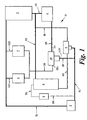
Fig.1 is a diagrammatic representation of an engine cooling system according to the invention; -
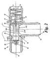
Fig.2 is a cross-section through a common control valve shown inFig.1 with a valve shuttle in a first position; -
Fig.3 is a cross-section based onFig.2 showing the valve shuttle in a second position; -
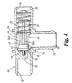
Fig.4 is a cross-section based onFig.2 showing a first modification to the common control valve shown inFigs.2 and3 ; -
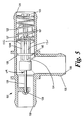
Fig.5 is a cross-section based onFig.2 showing a second modification to the common control valve shown inFigs.2 and3 ; -
Fig.6 is a cross-section based onFig.5 showing a third modification to the common control valve shown inFigs.2 and3 ; and -
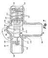
Fig.7 is a cross-section based onFig.5 showing a fourth modification to the common control valve shown inFigs.2 and3 ; - With particular reference to
Fig.1 , a motorvehicle cooling system 10 comprises a primary cooling circuit having an air-cooledradiator 8 for cooling a liquid coolant for theengine 3. Apump 2 circulates the coolant through theengine 3 and then to theradiator 8 or to a bypass BL through an engine return line ER and back to thepump 2 through a primaryflow control valve 5 and a pump return line RL. The primaryflow control valve 5 is usually simply referred to as the thermostat. Here it will be referred to as themain thermostat 5 to avoid any confusion with other parts of the cooling system. An appropriatemain thermostat 5 is described inEP-A-0794327 although conventional thermostats may be used. The bypass BL is arranged in parallel to theradiator 8 between the engine return line ER and themain thermostat 5. Coolant that has been cooled by theradiator 8 passes along a radiator return line RR to themain thermostat 5 and then back to thepump 2 through a pump return line RL. Themain thermostat 5 controls the flow through theradiator 8, preventing flow until theengine 3 has reached an appropriate running temperature. However, as with most valves of this type, themain thermostat 5 also controls the flow in the bypass line BL. Anexpansion tank 9 is connected at an upper end to the top of theradiator 8 by a degas supply line DS and is connected at a lower end to the return line RL by a degas return line DR. - The
engine cooling system 10 also includes an auxiliaries cooling circuit which comprises first and second liquid to liquid auxiliary heat exchangers in the form of atransmission oil cooler 6 and an engine oil cooler 7 connected in parallel between the engine supply line SL and acommon control valve 20, more conveniently referred to as the heater diverter valve. Coolant is supplied to thetransmission oil cooler 6 through a first cooler supply line CS1 and to the engine oil cooler 7 through a second cooler supply line CS2. The coolant outputs from thetransmission oil cooler 6 and the engine oil cooler 7 are combined and fed as a coolers or auxiliaries return flow to theheater diverter valve 20 through a coolers return line CR. - Also included in the
engine cooling system 10 is a heater circuit comprising aheater 4 having a liquid to air heat exchanger for vehicle cabin heating. Theheater 4 is connected by a heater supply line HS to the engine return line ER between theengine 3 and theradiator 8. After flowing through theheater 4, the coolant is returned to theheater diverter valve 20 as a heater return flow through a heater return line HR. The coolers return flow and the heater return flow are returned to the primary cooling circuit at the pump return line RL through a secondaries return line SR. - With particular reference to
Figs.2 and3 , theheater diverter valve 20 comprises ahousing 30 made as a one-piece plastics moulding defining avalve chamber 41. Afirst inlet 31 connects thevalve chamber 41 to the heater return line HR and asecond inlet 32 connect thevalve chamber 41 to the coolers return line CR. Anoutlet 33 is connected to the secondaries return line SR to return coolant to the primary cooling circuit. Thehousing 30 is in the form of a conventional tee-piece for connection to flexible hoses, the first andsecond inlets outlet 33 having its axis perpendicular to that of the inlets. - A
valve assembly 42 is carried in thevalve chamber 41 and comprises avalve shuttle 24 formed as a plastics moulding and a thermally-responsive actuator 19 carried within theshuttle 24. A biasing means in the form of ahelical spring 22 acts to bias theshuttle 24 towards thesecond inlet 32. Thevalve chamber 41 is formed as an extension of the bore of thefirst inlet 31 and at a step of this bore with the smaller bore of the second inlet 32 a chamferedvalve seat 43 is formed for cooperation with a corresponding valve seat on amain valve member 25 formed as a collar integral with theshuttle 24. - The thermally-
responsive actuator 19 is a generally conventional wax actuator (generally referred to as wax capsule) having an actuator orcapsule body 21 and apushrod 28 extending towards thesecond inlet 32 for cooperation with anabutment 29 in thesecond inlet 32. Theabutment 29 is carried on three spokes and is formed as an integral part of thehousing 30. Thecapsule body 21 has a metal casing which forms a temperature sensitive portion which can transmit heat to wax for driving thepushrod 28. Thecapsule body 21 is cylindrical, being a push fit in a bore of theshuttle 24 so that the capsule body is almost entirely within theshuttle 24. Theshuttle 24 has fourradial fins 27 which form a fluted end portion at is end adjacent thefirst inlet 31. Eachfin 27 is aligned with a correspondinglongitudinal rib 27A, the bore intersecting theribs 27A to define fourapertures 24A to the side of themain valve member 25 which is towards thefirst inlet 31. Theseapertures 24A allow heater return flow to directly contact thecapsule casing 21. - Each
fin 27 has astep 26 to provide a reaction surface for thehelical spring 22. Thehelical spring 22 is a sliding fit on thefins 27 while thespring 22 is a sliding fit in the bore offirst inlet 31. Hence thehelical spring 22 acts as a guide for thevalve shuttle 24. A ladder-shapedretainer 23 extends across thefirst inlet 31 through diametrically opposed windows in thehousing 30 to provide a reaction surface for thehelical spring 22. - Operation of the primary cooling circuit is conventional and thus will be described relatively briefly. When the
engine 3 is started from cold it is desirable to increase its temperature as quickly as possible to reduce emissions and to increase fuel economy. During initial running of the engine, themain thermostat 5 prevents any coolant flowing through theradiator 8 while allowing flow through the bypass BL. Once theengine 3 has been operated for a sufficient period for it to have reached normal operating temperature, which in this case is 90°, themain thermostat 5 starts to close off the bypass BL to allow coolant to begin flowing through theradiator 8 and prevent theengine 3 from overheating. - Operation of the
heater diverter valve 20 is as follows. Following a cold start of theengine 3, thevalve 20 is in the state shown inFig.2 . Themain valve member 25 is held on theseat 43 by thespring 22 to shut off the coolers return flow from thesecond inlet 32 while the heater return flow through thefirst inlet 31 into thevalve chamber 41 and through theoutlet 33 is unrestricted. The temperature of the heater return flow is sensed by thecapsule body 21 so that as the temperature of the heater return flow increases, thepushrod 28 starts to generate a force in opposition to the preload of thespring 22. However, the coolers return flow remains blocked while the coolant entering the chamber is below a first pre-determined temperature, in this case 74°C. At this temperature the force generated by thepushrod 28 overcomes the pre-load of thespring 22 and theshuttle 24 starts to move away from thesecond inlet 32 to allow the coolers return flow from thesecond inlet 32 to theoutlet 33 while continuing to allow the heater return flow from thefirst inlet 31 to theoutlet 33. As the temperature of the heater return flow continues to rise, the force generated by the wax actuator continues to increase and theshuttle 24 is moved further and further away from thesecond inlet 32, as shown inFig.3 . - When the heater return flow reaches or exceeds a second pre-determined temperature, in this case 86°C, the
pushrod 28 is fully extended and thevalve member 25 is positioned more or less in the middle of theoutlet 33. In this position it provides some restriction on the heater return flow from thefirst inlet 31 while allowing the least restriction to the coolers return flow from thesecond inlet 32. - By preventing coolers return flow following a cold start of the
engine 3 until the temperature of the heater return flow reaches 74°C, the cooling system provides as much heat as possible to theheater 4 so that the occupants of the motor vehicle can obtain the maximum benefit from theheater 4. During this phase of operation thetransmission oil cooler 6 and the engine oil cooler 7 are effectively isolated and do not absorb any of the heat being generated by theengine 3. Thus the time for theengine 3 to warm up is reduced, further helping theheater 4 to become effective more quickly. Furthermore, the usual situation following a cold start is that the temperature of the coolant in the engine supply line SL is above the temperatures of the oils flowing through thetransmission oil cooler 6 and the engine oil cooler 7, even when the temperature of the heater return flow has risen above 74°C and theheater diverter valve 20 has started to allow coolers return flow through the coolers return line CR. Under these conditions, the warmer coolant flowing through the auxiliaries cooling circuit heats these oils, thereby helping to reduce friction losses in the transmission and theengine 3. In due course the oil temperatures rise, the temperature of the coolers return flow becoming greater than that of the engine return flow in the engine supply line SL and thecoolers 6 and 7 act to extract heat from the oils. - By restricting the heater return flow when the heater return flow reaches the second pre-determined temperature of 86°C, the pressure drop across the
heater 4 is reduced so that the rate of coolant flow through theradiator 8 is increased. This reduces the temperature of the coolant circulated through the radiator return line RR, themain thermostat 5, the pump return line RL and the engine supply line to improve the effectiveness of the engine oil cooler 7 and thetransmission oil cooler 6. When the vehicle is operating in a cool climate and the heater is likely to be in use, the temperature of the heater return flow is unlikely to reach 86°C so the conditions just described tend to occur only when the ambient temperature is higher. - If the requirements for cabin heat from the
heater 4 are reduced, there is a measurable increase in the temperature of the heater return flow and this is used to control operation of theheater diverter valve 20. When theheater 4 is supplying maximum cabin heat the temperature of the heater return flow is approximately 12°C below the temperature when no heat is being supplied and this difference in temperatures can be used when designing the cooling system to determine the second pre-determined temperature of the heater return flow. - In the usual situation where the
pump 2 is driven by the engine and pump speed is proportional to engine speed, the pressure of the coolant in the engine supply line SL increases with engine speed, thereby increasing both the flows and the pressure differences in the various parts of the cooling system. If for some reason theheater diverter valve 20 became inoperative (perhaps through failure of the wax capsule 21) so that thesecond inlet 32 remains closed there is a possibility that the engine and transmission oils would become of overheated. However, the pre-load of the helical spring can be set such that at low to moderate engine speeds the pre-load is sufficient to prevent flow through thesecond inlet 32 but at higher engine speeds theshuttle 24 is moved by the increasing pressure at the second inlet to allow some coolant flow through theoil coolers 6 and 7. Indeed, a cooling system which uses a heater diverter valve which has such a spring loaded valve shuttle without the thermally responsive actuator may provide a useful improvement over known cooling systems. - When the
shuttle 24 moves away from thesecond inlet 32 to allow the coolers return flow from thesecond inlet 32 to theoutlet 33, there is an additional advantage from merging the coolers return flow with the heater return flow in that the coolers return flow is through a relatively small cross-sectional area as it is carried past themain valve member 25 and this creates a venturi effect which can enhance the heaters return flow. - In the first modification shown in
Fig.4 most parts are the same as or similar to those inFigs.2 and3 so carry the same reference. The main difference between this modified valve and theheater diverter valve 20 shown inFigs.2 and3 is that themain valve member 25 is at the extreme end of theshuttle 24 closest to thesecond inlet 32. Also, the angle of the chamfer on thevalve member 25 and the corresponding angle on thevalve seat 43 are more acute. This allows the use of ashorter capsule body 21 and ashorter valve shuttle 24. Operation of the modifiedheater diverter valve 20 is otherwise the same as described above. - In the second modification shown in
Fig.5 parts which are the same as or similar to those inFigs.2 and3 carry the same reference but with the addition of 100. Structurally, the main difference between the modifiedheater diverter valve 120 and theheater diverter valve 20 shown inFigs.2 and3 is that theshuttle 124 is longer and hasapertures 140 on the side of thevalve member 125 to expose thecapsule body 121 to the coolers return flow from thesecond inlet 132. Also, thepushrod 128 has a longer travel so that when it is at its maximum extension it pushes the valve member 125 a small distance into the bore of thefirst inlet 131. - Operation of this modified
heater diverter valve 120 differs from that of theheater diverter valve 20 in that when the heater return flow from thefirst inlet 131 rises above the first predetermined temperature to unseat thevalve member 125 and allow coolers return flow from thesecond inlet 132, then thecapsule body 121 can draw significant heat from the coolers return flow as well as the heater return flow. Thewax capsule 119 thus becomes responsive to a combination of the temperature and flow of the coolant entering through thefirst inlet 131 and the temperature and flow of the coolant entering through the second inlet. Before thevalve member 125 becomes unseated, the coolant in thesecond inlet 132 is stagnant so thecapsule 119 is at this stage responsive to only the temperature of the heater return flow entering through thefirst inlet 131. - As the temperatures of the heater return flow from the
first inlet 131 and of the coolers return flow from thesecond inlet 132 continue to rise, the force generated by thecapsule 119 continues to increase and theshuttle 124 and thevalve member 125 are moved further and further away from thesecond inlet 132. When the coolant in the chamber reaches or exceeds the second pre-determined temperature thepushrod 128 is fully extended so that thevalve member 125 is engaged with the first inlet 131 (as shown inFig.5 ) and so substantially shuts-off the heater return flow while allowing unrestricted coolers return flow from thesecond inlet 132. It will be appreciated that there may be a small flow in from thefirst inlet 131 due to clearance between thevalve member 125 and thefirst inlet 131. The advantage of this arrangement is that it allows the maximum flow through thecoolers 6 and 7 at very high coolant temperatures when hot air output from theheater 4 is an unlikely requirement. - As an alternative to the
apertures 121 to the side of thevalve member 125 towards thesecond inlet 132, the capsule body may be inserted in the bore of theshuttle 124 so that an end part adjacent thepushrod 128 remains exposed. This gives the same functionality as theapertures 121. A similar modification can be made to the heater diverter valves shown inFigs. 2 and3 and inFig.4 and can be readily made simply by inserting a spacer in the end of the bore of theshuttle 24. - In the third modification shown in
Fig.6 parts which are the same as or similar to those inFig.2s and3 carry the same reference but with the addition of 200. Structurally, the main difference between this modifiedvalve 220 and theheater diverter valve 20 shown inFigs.2 and3 is that theshuttle 224 has anancillary valve member 225A spaced from themain valve member 225 and hasapertures 240 between themain valve member 225 and theancillary valve member 225A to expose thecapsule body 221 to the coolant in thevalve chamber 241 in the region between thevalve members - Operation of the
heater diverter valve 220 differs from that of thevalve 20 in that when the heater return flow from thefirst inlet 231 rises above the first predetermined temperature to unseat themain valve member 225 and allow coolers return flow from thesecond inlet 232, then thecapsule body 221 can draw some heat from the coolers return flow as well as the heater return flow. Thecapsule 219 thus becomes responsive to a combination of the temperature and flow of the coolant entering through thefirst inlet 231 and the temperature and flow of the coolant entering through thesecond inlet 232. As the temperatures of the heater return flow and the coolers return flow continue to rise, theshuttle 224 moves further away from thesecond inlet 232. When the coolant in thevalve chamber 241 reaches or exceeds the second pre-determined temperature thepushrod 228 is fully extended so that theancillary valve member 225A is engaged with the bore of thefirst inlet 231 as is shown in respect of the further modification shown inFig.7 . At this extent of travel of theshuttle 219, theancillary valve member 225A substantially shuts-off the heater return flow while themain valve member 225 allows unrestricted coolers return flow. There may be a small flow through thefirst inlet 231 due to clearance between theancillary valve member 225A and the bore of thefirst inlet 231. The advantage of this arrangement is similar to that of theFig.5 modification in that it allows the maximum flow through thecoolers 6 and 7 at very high coolant temperatures when hot air output from theheater 4 is an unlikely requirement. However, it does not require a very large travel forpushrod 228 of thewax capsule 219. - In the fourth modification shown in
Fig.7 all the parts except for the housing 230A are the same as those shown inFig.6 so carry the same reference. The main difference between the housing 230A and thehousing 230 inFig.6 is a generallyannular bulge 260 in the wall defining thevalve chamber 241. This modification only affects the situation when theshuttle 224 is at an intermediate position and coolant is flowing in from the first andsecond inlets bulge 260 allows for a greater volume for thevalve chamber 241 so that the coolers return flow and the heater return flow can mix prior to reaching thecapsule casing 221. The temperature of the heater return flow remains dominant because it is able to directly impinge upon thecapsule body 221 through theapertures 224A as well as mixing with the coolers return flow in thevalve chamber 241. - Although the
heater diverter valves
Claims (18)
- An engine cooling system (10) comprising a primary cooling circuit having a radiator (8) for cooling liquid coolant for the engine (3), a pump (2) to circulate the coolant through an engine supply line (SL) to the engine, from the engine to the radiator and from the radiator back to the pump through a pump return line (RL), an auxiliaries cooling circuit having at least one auxiliary heat exchanger (6,7) for cooling one or more further liquids and arranged so that coolant can flow from the engine supply line through the or each auxiliary heat exchanger and be returned as an auxiliaries return flow into the pump return line and a heater circuit having a heater (4) comprising a liquid to air heat exchanger and arranged so that coolant can flow from the engine supply line through the engine and then through the heater and be returned as a heater return flow into the pump return line, wherein a common control valve (20,120, 220) is provided between the or each auxiliary heat exchanger (6,7) and the pump return line (RL) and between the heater (4) and the pump return line to control both the auxiliaries return flow and the heater return flow and wherein the common control valve (20,120, 220) comprises a housing (30,130, 230) defining a valve chamber (41, 141,241), outlet (33,133,233) connected to the pump return line (RL) and a valve assembly (42,142, 242) mounted in the valve chamber,
characterised in that said common control valve also comprises a first inlet (31, 131, 231) connecting the heater (4) to the valve chamber for the heater return flow and a second inlet (32, 132, 232) connecting the or each auxiliary heat exchanger (6, 7) to the valve chamber for the auxiliaries return flow. - A cooling system as claimed in claim 1 in which the common control valve (20,120, 220) is operable to prevent the auxiliaries return flow until the heater return flow reaches a first pre-determined temperature.
- A cooling system as claimed in claim 1 or claim 2 in which the common control valve (20,120, 220) is operable to restrict the heater return flow when the heater return flow exceeds a second predetermined temperature.
- A cooling system as claimed in claim 1 or claim 2 in which the common control valve (20,120, 220) is operable to restrict the heater return flow when a combination of the auxiliaries return flow and the heater return flow exceeds a second pre-determined temperature.
- A cooling system as claimed in claim 2 or any claim dependent therefrom in which the common control valve (20,120, 220) comprises a thermally-responsive actuator (19,119, 219) having a temperature sensitive portion (21,. 121,221) that is exposed to the heater return flow when the heater return flow is below the first predetermined temperature.
- A cooling system as claimed in claim 5 in which the temperature sensitive portion (21, 121, 221) is exposed to both the heater return flow and the auxiliaries return flow.
- A cooling system as claimed in claim 5 or in claim 6 in which, when the common control valve (20,120, 220) permits both the auxiliaries return flow and the heater return flow, the auxiliaries return and the heater return flows are mixed prior to reaching said temperature sensitive portion (21,121, 221) so that the temperature sensed by the temperature sensitive portion is dependent upon a combination of the temperature and the flow rate of the heater return flow and the temperature and flow rate of the auxiliaries return flow.
- A cooling system as claimed in any preceding claim in which the valve assembly comprises a valve shuttle (24, 124,224) and a biasing means (22,122, 222) to bias the valve shuttle towards an auxiliaries closed position in which heater return flow through the first inlet to the outlet is substantially unrestricted while auxiliaries return flow through the second inlet is prevented.
- A cooling system as claimed in claim 8 when dependent upon claim 5 in which the valve assembly (42,142, 242) further comprises the thermally-responsive actuator (19,119, 219), the thermally-responsive actuator being arranged to urge the valve shuttle (24,124, 224) against the biasing means (22,122, 222) to allow auxiliaries return flow through the second inlet (32,132, 232) to the outlet (33,133, 233) when the heater return flow reaches the first predetermined temperature while continuing to allow the heater return flow from the first inlet (31,131, 231) through to the outlet.
- A cooling system as claimed in claim 9 when dependent upon claim 3 or claim 4 in which, with increasing temperature of the heater return flow, the valve shuttle (124, 224) moves further against the biasing means (122,222) to obstruct heater return flow through the first inlet (131,231) when the heater return flow temperature reaches the second predetermined temperature while continuing to allow the auxiliaries return flow from the second inlet (132,232) through to the outlet (133,233).
- A cooling system as claimed in claim 9 or in claim 10 in which the valve shuttle (24, 124, 224) has a main valve member (25, 125, 225) which cooperates with the housing (30, 130, 230) to close the second inlet (32, 132, 232) and to obstruct the first inlet (31, 131, 231).
- A cooling system as claimed in any of claims 10 to 11 in which the valve shuttle (224) has a main valve member (225) which cooperates with the housing (230) to close the second inlet (232) and an ancillary valve member (225A) which cooperates with the housing (230) to obstruct the first inlet (231).
- A cooling system as claimed in any of claims 8 to 12 when dependent upon claim 6 in which the thermally-responsive actuator (19, 119, 219) comprises an actuator body fast with the valve shuttle (24,124, 224) and a pushrod (28,128, 228) extending from one end of the valve shuttle (24,124, 224) for cooperation with an abutment (29,129, 229) on the housing (30,130, 230), the actuator body including said temperature sensitive portion (21,121, 221).
- A cooling system as claimed in any of claims 8 to 13 in which the biasing means is a helical spring (22,122, 222) which is axially guided by the housing (30,130, 230) and is located in the first inlet (31,131, 231).
- A cooling system as claimed in claim 14 in which the valve shuttle (24, 124,224) has a fluted end portion (27,127, 227) which is engaged within the helical spring (22,122, 222) so that the valve shuttle (24,124, 224) is axially guided by the helical spring.
- A cooling system as claimed in claim 13 in which the valve shuttle (24,124, 224) is shaped to allow coolant to directly contact the temperature sensitive portion (21,121, 221) of the actuator body.
- A cooling system as claimed in claim 16 when dependent upon claim 11 in which the valve shuttle (124) is shaped to allow coolant to directly contact the temperature sensitive portion (121) of the actuator body on the side of the main valve member (125) towards the first inlet (131) and on the side of the main valve member towards the second inlet (132).
- A cooling system as claimed in claim 16 when dependent upon claim 12 in which the valve shuttle (224) is shaped to allow coolant to directly contact the temperature sensitive portion (221) of the actuator body between the main valve member (225) and the ancillary valve member (225A) and on the side of the main valve member towards the first inlet (231).
Applications Claiming Priority (3)
| Application Number | Priority Date | Filing Date | Title |
|---|---|---|---|
| GBGB0220521.9A GB0220521D0 (en) | 2002-09-04 | 2002-09-04 | A motor vehicle and a thermostatically controlled valve therefor |
| GB0220521 | 2002-09-04 | ||
| PCT/GB2003/003587 WO2004022941A1 (en) | 2002-09-04 | 2003-08-18 | Engine cooling systems |
Publications (2)
| Publication Number | Publication Date |
|---|---|
| EP1537308A1 EP1537308A1 (en) | 2005-06-08 |
| EP1537308B1 true EP1537308B1 (en) | 2011-10-12 |
Family
ID=9943468
Family Applications (1)
| Application Number | Title | Priority Date | Filing Date |
|---|---|---|---|
| EP03793848A Expired - Lifetime EP1537308B1 (en) | 2002-09-04 | 2003-08-18 | Engine cooling systems |
Country Status (4)
| Country | Link |
|---|---|
| US (1) | US7069880B2 (en) |
| EP (1) | EP1537308B1 (en) |
| GB (2) | GB0220521D0 (en) |
| WO (1) | WO2004022941A1 (en) |
Families Citing this family (25)
| Publication number | Priority date | Publication date | Assignee | Title |
|---|---|---|---|---|
| GB0310122D0 (en) | 2003-05-02 | 2003-06-04 | Ford Global Tech Llc | Temperature responsive flow control valves for engine cooling systems |
| JP4557756B2 (en) * | 2005-03-11 | 2010-10-06 | トヨタ自動車株式会社 | Electric motor cooling device and control method thereof, and abnormality determination method at the time of starting the cooling device |
| DE102005048286B4 (en) * | 2005-10-08 | 2007-07-19 | Itw Automotive Products Gmbh & Co. Kg | Method for operating a cooling system for an internal combustion engine |
| JP4631652B2 (en) * | 2005-10-25 | 2011-02-16 | トヨタ自動車株式会社 | COOLING SYSTEM, ITS CONTROL METHOD, AND AUTOMOBILE |
| FR2904856B1 (en) * | 2006-08-09 | 2008-11-14 | Peugeot Citroen Automobiles Sa | DEVICE FOR CONTROLLING A CIRCUIT CIRCUIT FOR A COOLANT AND A LUBRICATING OIL CIRCUIT FOR A VEHICLE HEAT ENGINE |
| US20080115747A1 (en) * | 2006-10-31 | 2008-05-22 | International Engine Intellectual Property Company, Llc | Coolant controller for an internal combustion engine |
| JP4877057B2 (en) * | 2007-05-07 | 2012-02-15 | 日産自動車株式会社 | Internal combustion engine cooling system device |
| US20090078220A1 (en) * | 2007-09-25 | 2009-03-26 | Ford Global Technologies, Llc | Cooling System with Isolated Cooling Circuits |
| CN101860178B (en) * | 2010-05-21 | 2012-05-30 | 上海海立特种制冷设备有限公司 | Improved structure of temperature control valve block of cooling system of wind generating set |
| KR101316463B1 (en) * | 2011-06-09 | 2013-10-08 | 현대자동차주식회사 | Integrated Heat Management System in Vehicle and Heat Management Method thereof |
| SE536185C2 (en) * | 2011-11-29 | 2013-06-18 | Scania Cv Ab | System for controlling the fluid flow in a vehicle |
| FR2996595B1 (en) * | 2012-10-08 | 2015-07-17 | Renault Sa | ARRANGEMENT FOR A MOTOR VEHICLE HAVING A REAR ENGINE, SYSTEM FOR DISTRIBUTING AN ENGINE COOLING FLUID |
| US10035404B2 (en) * | 2012-10-15 | 2018-07-31 | Ford Global Technologies, Llc | Thermostatically-controlled multi-mode coolant loops |
| KR101394051B1 (en) * | 2012-12-17 | 2014-05-09 | 현대자동차 주식회사 | Engine cooling system for vehicle and control method in the same |
| US8944017B2 (en) * | 2013-05-30 | 2015-02-03 | GM Global Technology Operations LLC | Powertrain cooling system with cooling and heating modes for heat exchangers |
| DE102013221574A1 (en) * | 2013-10-23 | 2015-04-23 | Behr Thermot-Tronik Gmbh | thermostatic valve |
| US9796244B2 (en) | 2014-01-17 | 2017-10-24 | Honda Motor Co., Ltd. | Thermal management system for a vehicle and method |
| WO2015179776A1 (en) | 2014-05-22 | 2015-11-26 | Cummins Inc. | Electrically driven cooling system for vehicular applications |
| US20160059672A1 (en) * | 2014-08-26 | 2016-03-03 | CNH Industrial America, LLC | Cooling system for a work vehicle |
| US9964019B2 (en) | 2014-11-19 | 2018-05-08 | Ford Global Technologies, Llc | Method and system for a dual loop coolant system |
| US10132403B1 (en) * | 2017-05-18 | 2018-11-20 | Ford Global Technologies, Llc | Engine and transmission temperature control system |
| US10520075B2 (en) * | 2017-05-31 | 2019-12-31 | Mahle International Gmbh | Apparatus for controlling the temperature of an oil cooler in a motor vehicle |
| GB2570695B (en) * | 2018-02-02 | 2020-02-26 | Ford Global Tech Llc | A connector |
| FR3093535B1 (en) * | 2019-03-04 | 2021-06-25 | Illinois Tool Works | COOLING SYSTEM OF A MOTOR VEHICLE |
| JP7464504B2 (en) * | 2020-11-16 | 2024-04-09 | 日本サーモスタット株式会社 | Thermo valve and thermo valve connector |
Family Cites Families (13)
| Publication number | Priority date | Publication date | Assignee | Title |
|---|---|---|---|---|
| US2797875A (en) * | 1955-04-11 | 1957-07-02 | Dole Valve Co | Thermal sensing car heater valve |
| FR2043151A5 (en) | 1969-04-16 | 1971-02-12 | Tubi Metallici Flessibil | |
| DE4121379A1 (en) * | 1990-07-11 | 1992-01-16 | Volkswagen Ag | Thermostatically controlled cooling system - is for IC engine and uses additional thermostat in vehicle heating circuit |
| GB2290123B (en) | 1994-06-09 | 1997-10-29 | Rover Group | A combined bypass and thermostat assembly |
| DE19508102C1 (en) * | 1995-03-08 | 1996-07-25 | Volkswagen Ag | Method for regulating a cooling circuit of an internal combustion engine, in particular for motor vehicles |
| GB9626047D0 (en) | 1996-12-14 | 1997-01-29 | Rover Group | A combined bypass and thermostat assembly |
| JP3374715B2 (en) | 1997-09-09 | 2003-02-10 | トヨタ自動車株式会社 | Cooling water circulation device for internal combustion engine |
| JPH11117739A (en) * | 1997-10-09 | 1999-04-27 | Toyota Motor Corp | Cooling water circulation device for internal combustion engine |
| EP0960759B1 (en) | 1998-05-26 | 2002-02-13 | Ford Global Technologies, Inc. | Heating for the passenger compartment of a motor vehicle |
| GB2366365B (en) | 2000-08-26 | 2004-07-21 | Land Rover Group Ltd | Engine Cooling Systems |
| US6530347B2 (en) * | 2000-09-18 | 2003-03-11 | Denso Corporation | Cooling apparatus for liquid-cooled internal combustion engine |
| JP2002227646A (en) | 2001-01-30 | 2002-08-14 | Isuzu Motors Ltd | Engine with EGR cooler |
| FR2820371B1 (en) * | 2001-02-06 | 2003-05-09 | Valeo Thermique Moteur Sa | VEHICLE COOLING AND HEATING DEVICE |
-
2002
- 2002-09-04 GB GBGB0220521.9A patent/GB0220521D0/en not_active Ceased
-
2003
- 2003-08-18 WO PCT/GB2003/003587 patent/WO2004022941A1/en not_active Ceased
- 2003-08-18 EP EP03793848A patent/EP1537308B1/en not_active Expired - Lifetime
- 2003-08-21 GB GB0319608A patent/GB2394277B/en not_active Expired - Fee Related
-
2005
- 2005-03-07 US US11/077,539 patent/US7069880B2/en not_active Expired - Lifetime
Also Published As
| Publication number | Publication date |
|---|---|
| US20050199193A1 (en) | 2005-09-15 |
| GB0220521D0 (en) | 2002-10-09 |
| GB0319608D0 (en) | 2003-09-24 |
| US7069880B2 (en) | 2006-07-04 |
| WO2004022941A1 (en) | 2004-03-18 |
| GB2394277B (en) | 2005-10-26 |
| EP1537308A1 (en) | 2005-06-08 |
| GB2394277A (en) | 2004-04-21 |
Similar Documents
| Publication | Publication Date | Title |
|---|---|---|
| EP1537308B1 (en) | Engine cooling systems | |
| US7124715B2 (en) | Engine cooling systems | |
| US7082903B2 (en) | Temperature responsive flow control valves for engine cooling systems | |
| CN103291435B (en) | Cooling water control valve gear | |
| WO2003095810A1 (en) | Electronically controlled thermostat | |
| US20020005179A1 (en) | Device for regulating the temperature of oil | |
| KR101018538B1 (en) | Vehicle cooling system | |
| EP1382813B1 (en) | Thermostat device | |
| US4410133A (en) | Two way fluid switchover valve with crossover protection | |
| EP1537307B1 (en) | Engine cooling systems | |
| US8047450B2 (en) | Temperature responsive flow control valve for an engine cooling system | |
| CN108361100A (en) | Cooling system and thermostat apparatus for internal combustion engine | |
| US5787845A (en) | Combined bypass and thermostat assembly | |
| EP3444461B1 (en) | Thermostat for cooling system of an internal combustion engine for vehicles | |
| WO1997033078A1 (en) | An engine and a cooling system therefor | |
| GB2455339A (en) | Temperature responsive flow control valve | |
| US10920654B2 (en) | Connector | |
| KR101047752B1 (en) | Valves for Heat Exchange of Fluids | |
| JP2005214075A (en) | Cooling device for internal combustion engine | |
| JP2010121456A (en) | Engine cooling system | |
| JPH0649115U (en) | Engine cooling system |
Legal Events
| Date | Code | Title | Description |
|---|---|---|---|
| PUAI | Public reference made under article 153(3) epc to a published international application that has entered the european phase |
Free format text: ORIGINAL CODE: 0009012 |
|
| 17P | Request for examination filed |
Effective date: 20050404 |
|
| AK | Designated contracting states |
Kind code of ref document: A1 Designated state(s): AT BE BG CH CY CZ DE DK EE ES FI FR GB GR HU IE IT LI LU MC NL PT RO SE SI SK TR |
|
| RBV | Designated contracting states (corrected) |
Designated state(s): DE FR |
|
| RAP1 | Party data changed (applicant data changed or rights of an application transferred) |
Owner name: FORD GLOBAL TECHNOLOGIES, LLC. |
|
| 17Q | First examination report despatched |
Effective date: 20100920 |
|
| GRAP | Despatch of communication of intention to grant a patent |
Free format text: ORIGINAL CODE: EPIDOSNIGR1 |
|
| GRAS | Grant fee paid |
Free format text: ORIGINAL CODE: EPIDOSNIGR3 |
|
| GRAA | (expected) grant |
Free format text: ORIGINAL CODE: 0009210 |
|
| AK | Designated contracting states |
Kind code of ref document: B1 Designated state(s): DE FR |
|
| REG | Reference to a national code |
Ref country code: DE Ref legal event code: R096 Ref document number: 60338767 Country of ref document: DE Effective date: 20111208 |
|
| PLBE | No opposition filed within time limit |
Free format text: ORIGINAL CODE: 0009261 |
|
| STAA | Information on the status of an ep patent application or granted ep patent |
Free format text: STATUS: NO OPPOSITION FILED WITHIN TIME LIMIT |
|
| 26N | No opposition filed |
Effective date: 20120713 |
|
| REG | Reference to a national code |
Ref country code: DE Ref legal event code: R097 Ref document number: 60338767 Country of ref document: DE Effective date: 20120713 |
|
| REG | Reference to a national code |
Ref country code: FR Ref legal event code: PLFP Year of fee payment: 14 |
|
| REG | Reference to a national code |
Ref country code: FR Ref legal event code: PLFP Year of fee payment: 15 |
|
| REG | Reference to a national code |
Ref country code: FR Ref legal event code: PLFP Year of fee payment: 16 |
|
| PGFP | Annual fee paid to national office [announced via postgrant information from national office to epo] |
Ref country code: FR Payment date: 20190717 Year of fee payment: 17 |
|
| PGFP | Annual fee paid to national office [announced via postgrant information from national office to epo] |
Ref country code: DE Payment date: 20200713 Year of fee payment: 18 |
|
| PG25 | Lapsed in a contracting state [announced via postgrant information from national office to epo] |
Ref country code: FR Free format text: LAPSE BECAUSE OF NON-PAYMENT OF DUE FEES Effective date: 20200831 |
|
| REG | Reference to a national code |
Ref country code: DE Ref legal event code: R119 Ref document number: 60338767 Country of ref document: DE |
|
| PG25 | Lapsed in a contracting state [announced via postgrant information from national office to epo] |
Ref country code: DE Free format text: LAPSE BECAUSE OF NON-PAYMENT OF DUE FEES Effective date: 20220301 |