EP1536386A1 - Reverse vending apparatus - Google Patents
Reverse vending apparatus Download PDFInfo
- Publication number
- EP1536386A1 EP1536386A1 EP04022319A EP04022319A EP1536386A1 EP 1536386 A1 EP1536386 A1 EP 1536386A1 EP 04022319 A EP04022319 A EP 04022319A EP 04022319 A EP04022319 A EP 04022319A EP 1536386 A1 EP1536386 A1 EP 1536386A1
- Authority
- EP
- European Patent Office
- Prior art keywords
- container
- conveyor
- rollers
- conveyor belts
- rotating rollers
- Prior art date
- Legal status (The legal status is an assumption and is not a legal conclusion. Google has not performed a legal analysis and makes no representation as to the accuracy of the status listed.)
- Granted
Links
- 238000000034 method Methods 0.000 claims abstract description 9
- 238000001514 detection method Methods 0.000 claims description 4
- 238000011144 upstream manufacturing Methods 0.000 claims description 4
- 230000007246 mechanism Effects 0.000 description 6
- 230000008859 change Effects 0.000 description 5
- 230000008901 benefit Effects 0.000 description 4
- 238000013461 design Methods 0.000 description 3
- 239000007788 liquid Substances 0.000 description 3
- 239000012530 fluid Substances 0.000 description 2
- 239000011521 glass Substances 0.000 description 2
- 238000009434 installation Methods 0.000 description 2
- 230000010354 integration Effects 0.000 description 2
- 238000012423 maintenance Methods 0.000 description 2
- 238000004519 manufacturing process Methods 0.000 description 2
- 230000001133 acceleration Effects 0.000 description 1
- 239000011248 coating agent Substances 0.000 description 1
- 238000000576 coating method Methods 0.000 description 1
- 238000010276 construction Methods 0.000 description 1
- 230000008878 coupling Effects 0.000 description 1
- 238000010168 coupling process Methods 0.000 description 1
- 238000005859 coupling reaction Methods 0.000 description 1
- 230000007423 decrease Effects 0.000 description 1
- 239000002184 metal Substances 0.000 description 1
- 230000007935 neutral effect Effects 0.000 description 1
- 230000003287 optical effect Effects 0.000 description 1
- 230000002093 peripheral effect Effects 0.000 description 1
- 239000004033 plastic Substances 0.000 description 1
- 230000008569 process Effects 0.000 description 1
- 238000012545 processing Methods 0.000 description 1
- 230000001681 protective effect Effects 0.000 description 1
- 230000009467 reduction Effects 0.000 description 1
- 230000001360 synchronised effect Effects 0.000 description 1
- 238000012360 testing method Methods 0.000 description 1
- 238000012549 training Methods 0.000 description 1
Images


Classifications
-
- G—PHYSICS
- G07—CHECKING-DEVICES
- G07F—COIN-FREED OR LIKE APPARATUS
- G07F7/00—Mechanisms actuated by objects other than coins to free or to actuate vending, hiring, coin or paper currency dispensing or refunding apparatus
- G07F7/06—Mechanisms actuated by objects other than coins to free or to actuate vending, hiring, coin or paper currency dispensing or refunding apparatus by returnable containers, i.e. reverse vending systems in which a user is rewarded for returning a container that serves as a token of value, e.g. bottles
- G07F7/0609—Mechanisms actuated by objects other than coins to free or to actuate vending, hiring, coin or paper currency dispensing or refunding apparatus by returnable containers, i.e. reverse vending systems in which a user is rewarded for returning a container that serves as a token of value, e.g. bottles by fluid containers, e.g. bottles, cups, gas containers
-
- B—PERFORMING OPERATIONS; TRANSPORTING
- B65—CONVEYING; PACKING; STORING; HANDLING THIN OR FILAMENTARY MATERIAL
- B65G—TRANSPORT OR STORAGE DEVICES, e.g. CONVEYORS FOR LOADING OR TIPPING, SHOP CONVEYOR SYSTEMS OR PNEUMATIC TUBE CONVEYORS
- B65G37/00—Combinations of mechanical conveyors of the same kind, or of different kinds, of interest apart from their application in particular machines or use in particular manufacturing processes
- B65G37/005—Combinations of mechanical conveyors of the same kind, or of different kinds, of interest apart from their application in particular machines or use in particular manufacturing processes comprising two or more co-operating conveying elements with parallel longitudinal axes
-
- B—PERFORMING OPERATIONS; TRANSPORTING
- B65—CONVEYING; PACKING; STORING; HANDLING THIN OR FILAMENTARY MATERIAL
- B65G—TRANSPORT OR STORAGE DEVICES, e.g. CONVEYORS FOR LOADING OR TIPPING, SHOP CONVEYOR SYSTEMS OR PNEUMATIC TUBE CONVEYORS
- B65G47/00—Article or material-handling devices associated with conveyors; Methods employing such devices
- B65G47/22—Devices influencing the relative position or the attitude of articles during transit by conveyors
- B65G47/24—Devices influencing the relative position or the attitude of articles during transit by conveyors orientating the articles
- B65G47/248—Devices influencing the relative position or the attitude of articles during transit by conveyors orientating the articles by turning over or inverting them
-
- Y—GENERAL TAGGING OF NEW TECHNOLOGICAL DEVELOPMENTS; GENERAL TAGGING OF CROSS-SECTIONAL TECHNOLOGIES SPANNING OVER SEVERAL SECTIONS OF THE IPC; TECHNICAL SUBJECTS COVERED BY FORMER USPC CROSS-REFERENCE ART COLLECTIONS [XRACs] AND DIGESTS
- Y02—TECHNOLOGIES OR APPLICATIONS FOR MITIGATION OR ADAPTATION AGAINST CLIMATE CHANGE
- Y02W—CLIMATE CHANGE MITIGATION TECHNOLOGIES RELATED TO WASTEWATER TREATMENT OR WASTE MANAGEMENT
- Y02W30/00—Technologies for solid waste management
- Y02W30/50—Reuse, recycling or recovery technologies
- Y02W30/60—Glass recycling
-
- Y—GENERAL TAGGING OF NEW TECHNOLOGICAL DEVELOPMENTS; GENERAL TAGGING OF CROSS-SECTIONAL TECHNOLOGIES SPANNING OVER SEVERAL SECTIONS OF THE IPC; TECHNICAL SUBJECTS COVERED BY FORMER USPC CROSS-REFERENCE ART COLLECTIONS [XRACs] AND DIGESTS
- Y02—TECHNOLOGIES OR APPLICATIONS FOR MITIGATION OR ADAPTATION AGAINST CLIMATE CHANGE
- Y02W—CLIMATE CHANGE MITIGATION TECHNOLOGIES RELATED TO WASTEWATER TREATMENT OR WASTE MANAGEMENT
- Y02W30/00—Technologies for solid waste management
- Y02W30/50—Reuse, recycling or recovery technologies
- Y02W30/62—Plastics recycling; Rubber recycling
Definitions
- the invention relates to a device for the return of containers, e.g. of cans and bottles of glass, plastic or metal and one unit for reverse vending machines for containers, whereby the containers with the help of a Conveying device in a lying position to an identification device in which the characteristic data of the containers are recorded become.
- a Conveying device in a lying position to an identification device in which the characteristic data of the containers are recorded become.
- it should be distinguished whether it is a disposable or a reusable container, as these are different Further treatment facilities are supplied.
- U1 is a unit for container-reverse vending machines known, which consists of two endless conveyor belts, which are arranged V-shaped, so that for example a bottle or a can on these conveyor belts in the direction of their longitudinal axis can be transported.
- Below the conveyor belts are two rollers arranged, which are driven by a rotary drive.
- the conveyor belts can be pivoted so that the container falls on the rollers and is turned by these. It detects a mounted above the conveyor unit Detect an identification code such as a barcode on the container. After detecting the barcode, the conveyor belts will turn pivoted, the stored on the rollers container raised again and then forwarded by the conveyor belts.
- Object of the present invention is therefore to provide a unit for container reverse vending machines to provide, characterized by a simpler and more stable mechanical structure and overall more cost-effective to be finished.
- This object is according to the invention in the unit for container take-back machines solved by the rollers as a hollow body are formed and have at least one breakthrough in the longitudinal direction.
- at least one conveyor is arranged in the rollers, wherein the conveyor belt is arranged in the region of the opening.
- the rotating rollers and the conveyor are stored separately, wherein in the Rotation of the rotating rollers, the lateral surface of the rollers, the conveyor belt the conveyor overlaps.
- the solution according to the invention has the advantage that through the training the rollers as a hollow body and the integration of a conveyor in the Cavity of the rotating rollers a compact and structurally simple unit has been created.
- the rollers for the rotation of the container and the Conveying device for the transversal transport of the container are independent controlled by each other, so that when rotating the rollers, the conveyor not moved.
- the drive motor at the solution according to the invention in a simple manner outside the rotating rollers be attached.
- the arrangement has the advantage that the position of the conveyor belt is fixed and during the rotational movement the rollers does not change.
- the drive motors for the rollers and the Conveyor belts are not additional motors for the tilting or pivoting movements required. Because only one engine for the movement of the conveyor belts required, can synchronize the movement of both conveyor belts be ensured.
- the container is in the transport position transported by the conveyor belts. If the rollers are rotated, then the bottle raised slightly by the lateral surfaces of the rollers and from rotated the rollers so that a detector disposed above the rollers can detect a mounted on the container identification feature. Overall, the unit is very service and maintenance friendly, as the individual Components are easily accessible.
- a device in which a V-shaped Conveyor liquid container transported lying. With the help of a detector unit become characteristic features of the container, such. the contour or an identification code is detected. With the help of the V-shaped conveyor can entered container back to the upstream position or loading position to be led back. Above the conveyor are rotating rollers arranged with movable pivot bearings, the change in distance are laterally toward each other and away from each other. When moving with distance reduction, a container is removed from the conveyor lifted and rotated, leaving an identification code from the detector unit can be read. Are the rotating rollers moved apart, so they fall down on the V-shaped conveyor and can get in from there Direction of the longitudinal axis of the container to be transported. These Device requires a complex movement mechanism for lateral Move the rotating rollers and this space required and movement space, what the size of the entire device and also their stability is negatively affected.
- the document WO 02/12095 A1 forms the preamble to the method claim 13.
- two conveyors occupy two positions with associated conveyor belts.
- a first Position in which the conveyor belts form a V-shape, lies the container on the conveyor belts.
- the sponsors and the associated conveyor belts moved apart, so that in the then occupied second position room is released for below the conveyor belts arranged rotation rollers with fixed pivot bearings.
- the container falls due to its weight down on these rotating rollers and is rotated by this, with the help of a code reader on the To read container attached Identifikatikonscode.
- the conveyors are pivoted back to the first position with the conveyor belts, whereby the container lifted from the rotating rollers becomes. He can then be further promoted in the direction of its longitudinal axis.
- the lateral movement of the conveyor belts requires a complex movement mechanism and an associated large installation space.
- WO 02/12095 A1 and DE-A-201 12 651 further describe a Apparatus for handling liquid containers according to the respective The preamble of claims 15 and 17.
- This device is intended to be mechanical Being easy to set up and testing cans or bottles with any or allow substantially different cross section.
- Such Container shapes may have characteristic features and contours the first upon rotation of the container from a certain detection angle a detector unit can be seen from. Therefore, the detector unit detects characteristic features of the container, such as e.g. the contour, the identification code or the like, during the rotation of the container.
- means are provided for the two conveyor belts from a first position in which they support the container, laterally apart to move to a second position, leaving in the space between the conveyor belts a pair of rotating rollers with fixed pivot bearings comes to light.
- the container falls onto these rotating rollers down and it is then during the rotation of the container detecting its characteristic features with the help of the detector unit.
- the rotation rollers are designed as hollow bodies and have fixed pivot bearings.
- the rotation rollers can, for example be mounted in pivot bearings, which are rigid with the housing of a Return machines are connected.
- the relative position of the axes of rotation of Rotary rollers to each other does not change during operation.
- Farther is arranged stationarily within each rotation roller of the conveyor.
- the associated conveyor frame which carries the conveyor belt, can For example, rigidly connected to the housing of the return vending machine be.
- the conveyor belts of the two conveyors together form a V-shape. During operation, the conveyors change their relative position, unlike the subject of WO 02/12095 A1, not, i.
- the V shape is maintained throughout the operation. Accordingly, a additional movement mechanism for pivoting the conveyor belts (as in WO 02/12095 A1) or an additional movement mechanism for pivoting the rotating rollers (as in WO 98/02853 A1) not required. Therefore, the drive motor in the inventive Solution can be easily mounted outside of the rotating rollers.
- the arrangement has the advantage that fixes the position of the conveyor belt is and does not change during the rotational movement of the rollers. Except the drive motors for the rollers and the conveyor belts are no additional motors for the tilting or pivoting movements required. Since only one motor is required for the movement of the conveyor belts, can a synchronization of the movement of both conveyor belts ensured become.
- Each rotation roller has in its lateral surface in Longitudinal breakthrough. In the first position in which the container rests on the conveyor belts, the container protrudes with its peripheral surface in the interior of the rotation roller. Upon rotation of the rotation roller The outer surface overlaps the conveyor belt and covers it in a protective manner.
- the measures described in claim 14 allow acceleration of the identification process. A turning of the container can be omitted if the identification code is already detectable in the first position.
- the measures according to claim 16 ensure that the detector unit can accurately capture the contour of the container.
- the detector unit e.g. a camera, in this embodiment, no high demands set to the processing speed.
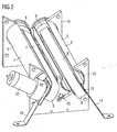
- Fig. 1 is an inventive unit for container-reverse vending machines for the transport and rotation of containers like Bottles and cans shown in a lying position.
- a unit is in a machine for returning containers such as glass bottles, PET bottles and cans.
- the containers are passed through an input port in the case of the machine, which is not shown here, on the Transport unit laid.
- the unit consists of two rollers 1 and 2, the order Axles 3 and 4 are rotatable.
- the rollers 1, 2 are hollow and have in their lateral surface 5 each have an opening 6.
- the rollers 1, 2 each have a conveying device 7, 8 is arranged.
- the conveyors 7, 8 each have a conveyor belt 9, the over pulleys 10 is performed.
- the conveying device 7, 8 is in such a way in the rollers 1,2 arranged that the conveyor belt 9 slightly below the lateral surface. 5 the rollers 5 is in the region of the opening 6.
- a container 11 rests on the conveyor belts 9 of the conveying devices 7, 8, which at an angle of about 120 degrees and thus V-shaped are arranged.
- the drive of the conveyors 7, 8 is advantageously carried out by a common electric motor 12 and a coupling 13.
- a container be transported in its longitudinal direction.
- the pulleys 10 of Conveyors 7, 8 are fixed to supports 14 which are fixed to a in Container automatic reverse vending machines arranged base frame are connected, so that the position of the conveying devices 7, 8 is fixed.
- the rotation rollers 1, 2 are in an engagement with the lateral surface 5 Storage rack 15 rotatably mounted.
- the rotation rollers 1,2 stored between two storage racks 15 to increased stability to achieve the storage of the rollers 1, 2.
- the Rollers 1, 2 at one end face with a ring gear 16 for driving the Rollers 1, 2 provided.
- the storage of rollers 1,2 on the drive side can either also by the storage rack 15 or by a storage take place on the sprocket axis 17.
- the gear 18 will turn driven by a second motor 199.
- the drive motor 19 for driving the rollers 1, 2 in a simple manner outside be attached to the roller. If the rotating rollers 1, 2 in rotation offset, then the lateral surface 5 of the rollers 1, 2 moves over the conveyor belt 9 of the respective conveyor device 7, 8 of time. One on the conveyor belts 9 of the conveyor 7, 8 transported container 11 is through the lateral surface 5 of the roller 1, 2 slightly raised and now stored on the lateral surfaces 5 of the two rollers 1,2. By the same direction Rotary movement of the rollers 1, 2, the container 11 is now rotated, so that above the rollers 1, 2 arranged detector such as a Scanner - not shown here - an attached to the container identification feature such as a barcode or other optical Coding can capture as soon as the feature in the coverage of the Detector comes.
- detector such as a Scanner - not shown here - an attached to the container identification feature such as a barcode or other optical Coding can capture as soon as the feature in the coverage of the Detector comes.
- the container 11 is arranged downstream of one of the transport device Place led. If, on the other hand, it is determined that it is a container 11 for which no pledge is paid out, the container 11 of the Transport device transported in the direction of the input area again.
- rollers 1,2 not made of a tube, but consist of individual strip-shaped segments 20 in the longitudinal direction of the rollers 1,2 are arranged and form the lateral surface 5 of the rollers 1,2.
- the Segments 20 are bent in a substantially circular shape so that they are sections form the cylindrical surface 5.
- the segments 20 are on each screwed onto annular support bodies 21 the two ends.
- the lateral surface 5 of Roll 1.2 to provide a coating to the frictional engagement between to influence the rollers 1,2 and the container 11 and running noise to soften the bottle during the rotation.
- the pulleys 10 of the conveyor belts 9 by means of a coupled belt drive 22 to drive and thereby enable a synchronous movement of the conveyor belts 9.
- the pulleys 10 of the conveyor 7,8 are with a Groove 23 provided for the belt 24.
- the belts 24 engage around the Motor 12 arranged deflection plate 25 and are of two other pulleys 26 led.
- a shaft 27 connects the deflection plate 25 with a Deflection pulley 28 for driving the second conveyor 7.
- a coupled belt drive 22 has the advantage over a clutch 13, that it is less susceptible to interference and therefore more suitable for continuous operation is.
- the wheels and belts of the belt drive 22 are also in one Area that is less susceptible to dirt than the intermediate area between the rollers 1,2, since here by the filled with residual fluid bottles soiling can occur due to leaking fluid.
Abstract
Description
Die Erfindung betrifft eine Vorrichtung für die Rücknahme von Behältern z.B. von Dosen und Flaschen aus Glas, Kunststoff oder Metall sowie eine Einheit für Rücknahmeautomaten für Behälter, wobei die Behälter mit Hilfe einer Fördereinrichtung in liegender Position zu einer Identifizierungseinrichtung transportiert werden, in der die charakteristischen Daten der Behälter erfasst werden. Insbesondere soll unterschieden werden, ob es sich um einen Einweg- oder einen Mehrwegbehälter handelt, da diese unterschiedlichen Weiterbehandlungseinrichtungen zugeführt werden.The invention relates to a device for the return of containers, e.g. of cans and bottles of glass, plastic or metal and one unit for reverse vending machines for containers, whereby the containers with the help of a Conveying device in a lying position to an identification device in which the characteristic data of the containers are recorded become. In particular, it should be distinguished whether it is a disposable or a reusable container, as these are different Further treatment facilities are supplied.
Aus der DE 201 12 651 U1 ist eine Einheit für Behälter-Rücknahmeautomaten bekannt, die aus zwei endlosen Förderbändern besteht, die V-förmig angeordnet sind, so dass beispielsweise eine Flasche oder eine Dose auf diesen Förderbändern in Richtung ihrer Längsachse transportiert werden kann. Unterhalb der Förderbänder sind zwei Walzen angeordnet, die durch einen Drehantrieb antreibbar sind. Die Förderbänder können verschwenkt werden, so dass der Behälter auf die Walzen fällt und von diesen gedreht wird. Dabei erkennt ein oberhalb der Fördereinheit angebrachter Detektor einen Identifikationscode wie einen Barcode auf dem Behälter. Nach der Erkennung des Barcodes werden die Förderbänder wiederum verschwenkt, wobei der auf den Walzen gelagerte Behälter wieder angehoben und dann von den Förderbändern weitergeleitet wird.From DE 201 12 651 U1 is a unit for container-reverse vending machines known, which consists of two endless conveyor belts, which are arranged V-shaped, so that for example a bottle or a can on these conveyor belts in the direction of their longitudinal axis can be transported. Below the conveyor belts are two rollers arranged, which are driven by a rotary drive. The conveyor belts can be pivoted so that the container falls on the rollers and is turned by these. It detects a mounted above the conveyor unit Detect an identification code such as a barcode on the container. After detecting the barcode, the conveyor belts will turn pivoted, the stored on the rollers container raised again and then forwarded by the conveyor belts.
Aus der EP 1 167 247 B1 ist eine Einrichtung bekannt, bei der die Transportbänder für die Translationsbewegung in die Walzen für die Rotationsbewegung des Behälters integriert sind , so dass während der Rotationsbewegung der Walzen die Förderbänder mitbewegt werden. From EP 1 167 247 B1 a device is known in which the conveyor belts for translational movement in the rollers for rotational movement the container are integrated, so that during the rotational movement the rollers are moved along the conveyor belts.
Bei den bekannten Förder- und Dreheinheiten für Behälter wie Flaschen oder Dosen ist jedoch der Aufbau aufwendig und kompliziert. Insbesondere der Mechanismus zum Verkippen der Förderer ist mechanisch aufwendig konstruiert und im Dauerbetrieb aufgrund von Verschleißerscheinungen sehr störanfällig. Auch die andere Lösung ist aufwendig, da diese Förderbänder mit den umlaufenden Umlenkrollen während der Rotationsbewegung der Walzen mitrotieren und daher kompliziert angetrieben sind.In the known conveying and rotating units for containers such as bottles or Cans, however, the construction is complicated and complicated. In particular the Mechanism for tilting the conveyor is constructed mechanically consuming and in continuous operation due to wear very susceptible to interference. The other solution is complicated because these conveyor belts with the rotating pulleys during the rotation of the Rotate rollers and therefore are driven complicated.
Aufgabe der vorliegenden Erfindung ist es daher, eine Einheit für Behälter-Rücknahmeautomaten bereitzustellen, die sich durch einen einfacheren und stabileren mechanischen Aufbau auszeichnet und insgesamt kostengünstiger zu fertigen ist.Object of the present invention is therefore to provide a unit for container reverse vending machines to provide, characterized by a simpler and more stable mechanical structure and overall more cost-effective to be finished.
Diese Aufgabe wird gemäß der Erfindung bei der Einheit für Behälter-Rücknahmeautomaten dadurch gelöst, dass die Walzen als Hohlkörper ausgebildet sind und zumindest einen Durchbruch in Längsrichtung aufweisen. In den Walzen ist jeweils zumindest eine Fördereinrichtung angeordnet, wobei das Förderband im Bereich des Durchbruchs angeordnet ist. Die Rotationswalzen und die Fördereinrichtung sind getrennt gelagert, wobei bei der Drehung der Rotationswalzen die Mantelfläche der Walzen das Förderband der Fördereinrichtung übergreift.This object is according to the invention in the unit for container take-back machines solved by the rollers as a hollow body are formed and have at least one breakthrough in the longitudinal direction. In each case at least one conveyor is arranged in the rollers, wherein the conveyor belt is arranged in the region of the opening. The rotating rollers and the conveyor are stored separately, wherein in the Rotation of the rotating rollers, the lateral surface of the rollers, the conveyor belt the conveyor overlaps.
Die erfindungsgemäße Lösung hat den Vorteil, dass durch die Ausbildung der Walzen als Hohlkörper und die Integration einer Fördervorrichtung in den Hohlraum der Rotationswalzen eine kompakte und baulich einfache Einheit geschaffen worden ist. Die Walzen für die Rotation des Behälters und die Fördervorrichtung für den transversalen Transport des Behälters sind unabhängig voneinander ansteuerbar, so dass beim Drehen der Walzen die Fördereinrichtung nicht mitbewegt wird. Im Unterschied zu einer vollständigen Integration des Förderbandes in einer Drehwalze kann der Antriebsmotor bei der erfindungsgemäßen Lösung auf einfache Weise außerhalb der Rotationswalzen angebracht werden. Die Anordnung hat den Vorteil, dass die Position des Förderbandes fixiert ist und sich während der Rotationsbewegung der Walzen nicht ändert. Außer den Antriebsmotoren für die Walzen und die Förderbänder sind keine zusätzlichen Motoren für die Kipp- oder Schwenkbewegungen erforderlich. Da nur ein Motor für die Bewegung der Förderbänder erforderlich ist, kann eine Synchronisierung der Bewegung beider Förderbänder sichergestellt werden. Der Behälter wird in der Transportstellung von den Förderbändern transportiert. Werden die Walzen gedreht, so wird die Flasche durch die Mantelflächen der Walzen gering angehoben und von den Walzen gedreht, so dass ein über den Walzen angeordneter Detektor ein auf dem Behälter angebrachtes Identifikationsmerkmal erfassen kann. Insgesamt ist die Einheit sehr service- und wartungsfreundlich, da die einzelnen Komponenten leicht zugänglich sind.The solution according to the invention has the advantage that through the training the rollers as a hollow body and the integration of a conveyor in the Cavity of the rotating rollers a compact and structurally simple unit has been created. The rollers for the rotation of the container and the Conveying device for the transversal transport of the container are independent controlled by each other, so that when rotating the rollers, the conveyor not moved. Unlike a complete one Integration of the conveyor belt in a rotary drum, the drive motor at the solution according to the invention in a simple manner outside the rotating rollers be attached. The arrangement has the advantage that the position of the conveyor belt is fixed and during the rotational movement the rollers does not change. Except the drive motors for the rollers and the Conveyor belts are not additional motors for the tilting or pivoting movements required. Because only one engine for the movement of the conveyor belts required, can synchronize the movement of both conveyor belts be ensured. The container is in the transport position transported by the conveyor belts. If the rollers are rotated, then the bottle raised slightly by the lateral surfaces of the rollers and from rotated the rollers so that a detector disposed above the rollers can detect a mounted on the container identification feature. Overall, the unit is very service and maintenance friendly, as the individual Components are easily accessible.
Gemäß eines weiteren Aspekts der Erfindung wird ein Verfahren zur Handhabung
von Behältern in liegender Stellung nach Anspruch 13 sowie Vorrichtungen
zur Handhabung von Behältern in liegender Stellung nach den Ansprüchen
15 und 17 angegeben.According to another aspect of the invention, there is provided a method of handling
of containers in a lying position according to
Aus der WO 98/02853 ist eine Vorrichtung bekannt, bei der ein V-förmiger Förderer Flüssigkeitsbehälter liegend transportiert. Mit Hilfe einer Detektoreinheit werden charakteristische Merkmale des Behälters, wie z.B. die Kontur oder ein Identifikationscode erfasst. Mit Hilfe des V-förmigen Förderers können eingegebene Behälter wieder in die vorgeordnete Position oder Beschickungsposition zurückgeführt werden. Oberhalb des Förderers sind Rotationswalzen mit ortsbeweglichen Drehlagern angeordnet, die unter Abstandsveränderung seitlich aufeinander zu und voneinander weg bewegbar sind. Bei der Bewegung mit Abstandsverringerung wird ein Behälter vom Förderer hochgehoben und gedreht, so dass ein Identifikationscode von der Detektoreinheit gelesen werden kann. Werden die Rotationswalzen auseinander bewegt, so fallen sie auf den V-förmigen Förderer herab und können von dort in Richtung der Längsachse der Behälter weiter transportiert werden. Diese Vorrichtung benötigt einen aufwendigen Bewegungsmechanismus zum seitlichen Bewegen der Rotationswalzen und hierfür den erforderlichen Bauraum und Bewegungsraum, was die Baugröße der gesamten Vorrichtung und auch ihre Stabilität negativ beeinflusst.From WO 98/02853 a device is known in which a V-shaped Conveyor liquid container transported lying. With the help of a detector unit become characteristic features of the container, such. the contour or an identification code is detected. With the help of the V-shaped conveyor can entered container back to the upstream position or loading position to be led back. Above the conveyor are rotating rollers arranged with movable pivot bearings, the change in distance are laterally toward each other and away from each other. When moving with distance reduction, a container is removed from the conveyor lifted and rotated, leaving an identification code from the detector unit can be read. Are the rotating rollers moved apart, so they fall down on the V-shaped conveyor and can get in from there Direction of the longitudinal axis of the container to be transported. These Device requires a complex movement mechanism for lateral Move the rotating rollers and this space required and movement space, what the size of the entire device and also their stability is negatively affected.
Das Dokument WO 02/12095 A1 bildet den Oberbegriff für den Verfahrensanspruch
13. Bei dem Verfahren nach diesem Dokument können zwei Förderer
mit zugehörigen Förderbändern zwei Stellungen einnehmen. In einer ersten
Stellung, in der die Förderbänder eine V-Form bilden, liegt der Behälter
auf den Förderbändern auf. Aus dieser Stellung werden die Förderer und die
zugehörigen Förderbänder auseinanderbewegt, so dass in der dann eingenommenen
zweiten Stellung Raum freigegeben wird für unterhalb der Förderbänder
angeordnete Rotationswalzen mit ortsfesten Drehlagern. Der Behälter
fällt infolge seiner Gewichtskraft nach unten auf diese Rotationswalzen
und wird durch diese gedreht, um mit Hilfe eines Codelesers den auf den
Behälter angebrachten Identifikatikonscode lesen zu können. Anschließend
werden die Förderer mit den Förderbändern wieder in die erste Stellung verschwenkt,
wodurch der Behälter von den Rotationswalzen hochgehoben
wird. Er kann dann in Richtung seiner Längsachse weiter gefördert werden.
Die seitliche Bewegung der Förderbänder erfordert einen aufwendigen Bewegungsmechanismus
und einen zugehörigen großen Bauraum.The document WO 02/12095 A1 forms the preamble to the
Die WO 02/12095 A1 sowie die DE-A-201 12 651 beschreiben weiterhin eine
Vorrichtung zur Handhabung von Flüssigkeitsbehältern nach dem jeweiligen
Oberbegriff der Ansprüche 15 und 17. Diese Vorrichtung soll mechanisch
einfach aufgebaut sein und die Prüfung von Dosen oder Flaschen mit beliebigem
oder wesentlich unterschiedlichem Querschnitt ermöglichen. Solche
Behälterformen können charakteristische Merkmale und Konturen aufweisen,
die erst bei Drehung des Behälters von einem bestimmten Erfassungswinkel
einer Detektoreinheit aus erkennbar werden. Daher erfasst die Detektoreinheit
charakteristische Merkmale des Behälters, wie z.B. der Kontur, des Identifikationscodes
oder ähnlichem, während der Drehung des Behälters. Auch
bei dieser Vorrichtung sind Mittel vorgesehen, um die beiden Förderbänder
aus einer ersten Stellung, in welcher sie den Behälter stützen, seitlich auseinander
in eine zweite Stellung zu bewegen, so dass im Zwischenraum zwischen
den Förderbändern ein Paar Rotationswalzen mit ortsfesten Drehlagern
zum Vorschein kommt. Der Behälter fällt auf diese Rotationswalzen
herab und es erfolgt dann während der Drehung des Behälters das Erfassen
seiner charakteristischen Merkmale mit Hilfe der Detektoreinheit. Auch diese
Vorrichtung benötigt einen aufwendigen Bewegungsmechanismus für die
seitliche Bewegung der Förderbänder und den zugehörigen Bauraum.WO 02/12095 A1 and DE-A-201 12 651 further describe a
Apparatus for handling liquid containers according to the respective
The preamble of
Es ist Aufgabe der Erfindung, ein Verfahren und Vorrichtungen anzugeben, die im Betrieb eine hohe Zuverlässigkeit bieten, konstruktiv eine kompakte Bauform ermöglichen sowie insgesamt service- und wartungsfreundlicher sind.It is an object of the invention to provide a method and devices which offer a high level of reliability during operation, a compact design Allow design and overall service and maintenance friendly are.
Bei den Lösungen nach dem Verfahrensanspruch 13 und den Vorrichtungsansprüchen
15 und 17 wird im Unterschied zum Stand der Technik ein neuer
Weg eingeschlagen. Die Rotationswalzen sind als Hohlkörper ausgebildet
und haben ortsfest angeordnete Drehlager. Die Rotationswalzen können beispielsweise
in Drehlagern gelagert sein, die starr mit dem Gehäuse eines
Rückgabeautomaten verbunden sind. Die relative Lage der Drehachsen der
Rotationswalzen zueinander verändert sich während des Betriebs nicht. Weiterhin
ist innerhalb einer jeden Rotationswalze der Förderer ortsfest angeordnet.
Das zugehörige Fördergestell, welches das Förderband trägt, kann
beispielsweise starr mit dem Gehäuse des Rückgabeautomaten verbunden
sein. Die Förderbänder der beiden Förderer bilden miteinander eine V-Form.
Während des Betriebs ändern die Förderer ihre relative Lage zueinander,
anders als bei dem Gegenstand nach der WO 02/12095 A1, nicht, d.h. die V-Form
wird während des gesamten Betriebs beibehalten. Demgemäß wird ein
zusätzlicher Bewegungsmechanismus zum Verschwenken der Förderbänder
(wie bei der WO 02/12095 A1) oder ein zusätzlicher Bewegungsmechanismus
zum Verschwenken der Rotationswalzen (wie bei der WO 98/02853 A1)
nicht benötigt. Daher kann der Antriebsmotor bei der erfindungsgemäßen
Lösung auf einfache Weise außerhalb der Rotationswalzen angebracht werden.
Die Anordnung hat den Vorteil, dass die Position des Förderbandes fixiert
ist und sich während der Rotationsbewegung der Walzen nicht ändert.
Außer den Antriebsmotoren für die Walzen und die Förderbänder sind keine
zusätzlichen Motoren für die Kipp- oder Schwenkbewegungen erforderlich.
Da nur ein Motor für die Bewegung der Förderbänder erforderlich ist, kann
eine Synchronisierung der Bewegung beider Förderbänder sichergestellt
werden. Der technische Aufwand ist demgemäß bei dieser erfindungsgemäßen
Lösung verringert und die mechanische Stabilität sowie die Betriebszuverlässigkeit
verbessert. Jede Rotationswalze hat in ihrer Mantelfläche in
Längsrichtung einen Durchbruch. In der ersten Stellung, in der der Behälter
auf den Förderbändern aufliegt, ragt der Behälter mit seiner Umfangsfläche
in den Innenraum der Rotationswalze. Bei Drehung der Rotationswalze
übergreift die Mantelfläche das Förderband und deckt dieses schützend ab.
Durch die Einbeziehung der Förderbänder in die Rotationswalzen und die
Anordnung ortsfester Förderer und ortsfester Drehlager für die Rotationswalzen
wird eine kleine, kompakte Bauform erreicht. Insgesamt ist die Einheit
sehr service- und wartungsfreundlich, da die einzelnen Komponenten leicht
erreichbar sind.In the solutions according to the
Die in Anspruch 14 beschriebenen Maßnahmen ermöglichen eine Beschleunigung
des Identifikationsprozesses. Ein Drehen des Behälters kann entfallen,
wenn der Identifikationscode bereits in der ersten Stellung erfassbar ist.The measures described in
Die Maßnahmen nach Anspruch 16 stellen sicher, dass die Detektoreinheit
die Kontur des Behälters genau erfassen kann. An die Detektoreinheit, z.B.
eine Kamera, werden bei dieser Ausführungsform keine hohen Anforderungen
an die Verarbeitungsgeschwindigkeit gestellt.The measures according to
Weitere Einzelheiten der Erfindung ergeben sich aus der nachfolgenden Beschreibung und der Zeichnung. Further details of the invention will become apparent from the following description and the drawing.
In der Zeichnung zeigen:
- Fig. 1:
- eine schematische Stirnansicht einer ersten Ausführungsform der erfindungsgemäßen Einheit für einen Rücknahmeautomaten für Behälter in der neutralen Position für den Transport des Behälters;
- Fig. 2:
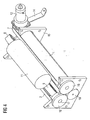
- eine Schrägansicht der Einheit aus Fig. 1;
- Fig. 3:
- eine Ansicht von unten der Einheit aus Fig. 1;
- Fig. 4:
- eine Seitenansicht der Einheit aus Fig. 1 mit einem Flüssigkeitsbehälter;
- Fig. 5
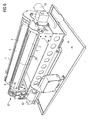
- eine rechte Schrägansicht einer zweiten Ausführungsform der Einheit;
- Fig. 6
- eine linke Schrägansicht der Einheit aus Fig. 5.
- Fig. 1:
- a schematic end view of a first embodiment of the unit for a reverse vending machine for containers in the neutral position for the transport of the container;
- Fig. 2:
- an oblique view of the unit of Fig. 1;
- 3:
- a bottom view of the unit of Fig. 1;
- 4:
- a side view of the unit of Figure 1 with a liquid container.
- Fig. 5
- a right oblique view of a second embodiment of the unit;
- Fig. 6
- a left oblique view of the unit of FIG. 5th
In Fig. 1 ist eine erfindungsgemäße Einheit für Behälter-Rücknahmeautomaten
für den Transport und die Rotation von Behältern wie
Flaschen und Dosen in liegender Stellung dargestellt. Eine solche Einheit
befindet sich in einem Automaten zur Rückgabe von Behältern wie Glasflaschen,
PET-Flaschen und Dosen. Die Behälter werden durch eine Eingabeöffnung
im Gehäuse des Automaten, die hier nicht dargestellt ist, auf die
Transporteinheit gelegt. Die Einheit besteht aus zwei Walzen 1 und 2, die um
Achsen 3 und 4 drehbar sind. Die Walzen 1, 2 sind hohlförmig ausgebildet
und weisen in ihrer Mantelfläche 5 jeweils einen Durchbruch 6 auf. In den
Walzen 1, 2 ist jeweils eine Fördervorrichtung 7, 8 angeordnet. Die Fördervorrichtungen
7, 8 weisen jeweils ein Förderband 9 auf, das über Umlenkrollen
10 geführt wird. Die Fördervorrichtung 7, 8 ist derart in den Walzen 1,2
angeordnet, dass sich das Förderband 9 etwas unterhalb der Mantelfläche 5
der Walzen 5 im Bereich des Durchbruchs 6 befindet. In der Transportstellung,
wie dies in Fig. 4 dargestellt ist, ruht ein Behälter 11 auf den Förderbändern
9 der Fördervorrichtungen 7, 8, die zueinander in einem Winkel von
ca. 120 Grad und somit V-förmig angeordnet sind. Der Antrieb der Fördervorrichtungen
7, 8 erfolgt vorteilhafterweise durch einen gemeinsamen Elektromotor
12 und eine Kupplung 13. Über das Fördersystem 7, 8 kann ein Behälter
in seiner Längsrichtung transportiert werden. Die Umlenkrollen 10 der
Fördervorrichtungen 7, 8 sind an Stützen 14 befestigt, die fest mit einem im
Behälter-Rücknahmeautomaten angeordneten Grundgestell verbunden sind,
so dass die Position der Fördervorrichtungen 7, 8 fixiert ist.In Fig. 1 is an inventive unit for container-reverse vending machines
for the transport and rotation of containers like
Bottles and cans shown in a lying position. Such a unit
is in a machine for returning containers such as glass bottles,
PET bottles and cans. The containers are passed through an input port
in the case of the machine, which is not shown here, on the
Transport unit laid. The unit consists of two
Die Rotationswalzen 1,2 sind in einem an der Mantelfläche 5 angreifenden
Lagergestell 15 drehbeweglich gelagert. Vorzugsweise sind die Rotationswalzen
1,2 zwischen zwei Lagergestellen 15 gelagert, um eine erhöhte Stabilität
der Lagerung der Walzen 1, 2 zu erreichen. Vorteilhafterweise sind die
Walzen 1, 2 an einer Stirnseite mit einem Zahnkranz 16 zum Antrieb der
Walzen 1, 2 versehen. Die Lagerung der Walzen 1,2 an der Antriebsseite
kann entweder ebenfalls durch das Lagergestell 15 oder aber durch eine Lagerung
an der Zahnkranzachse 17 erfolgen. Über ein Zahnrad 18, das mit
den beiden Zahnkränzen 16 der Walzen 1, 2 im Eingriff steht, können die
Walzen 1, 2 in Rotation versetzt werden. Das Zahnrad 18 wird wiederum
durch einen zweiten Motor 199 angetrieben. Insbesondere kann der Antriebsmotor
19 für den Antrieb der Walzen 1, 2 in einfacher Weise außerhalb
der Walze angebracht werden. Werden die Rotationswalzen 1, 2 in Rotation
versetzt, so bewegt sich die Mantelfläche 5 der Walzen 1, 2 über das Förderband
9 der jeweiligen Fördervorrichtung 7, 8 hinweg. Ein auf den Förderbändern
9 der Fördervorrichtung 7, 8 transportierter Behälter 11 wird durch
die Mantelfläche 5 der Walze 1, 2 geringfügig angehoben und lagert nun auf
den Manteloberflächen 5 der beiden Walzen 1,2. Durch die gleichsinnige
Drehbewegung der Walzen 1, 2 wird nun der Behälter 11 in Rotation versetzt,
so dass ein oberhalb der Walzen 1, 2 angeordneter Detektor wie ein
Scanner - hier nicht dargestellt - ein an dem Behälter angebrachtes Identifikationsmerkmal
wie beispielsweise einen Barcode oder eine andere optische
Codierung erfassen kann, sobald das Merkmal in den Erfassungsbereich des
Detektors kommt. Während der Rotationsbewegung der Walzen 1, 2 stehen
vorteilhafterweise die Förderbänder 9 der Fördervorrichtungen 7, 8 still. Es ist
jedoch auch denkbar, dass die Förderbänder 9 während der Drehbewegung
der Walzen 1, 2 nicht angehalten werden. Da die Rotationswalzen 1, 2 und
die Fördervorrichtungen 7, 8 voneinander unabhängig gelagert sind, ist die
Drehbewegung der Walzen 1, 2 und die Bewegung der Förderbänder 9 der
Fördervorrichtungen 7, 8 unabhängig voneinander durchführbar. Da die Fördervorrichtungen
7,8 nur von einem Motor angetrieben werden, ist eine Synchronisierung
der Förderbewegung der Fördervorrichtungen 7,8 sichergestellt.The
Durch den gemeinsamen Zugriff des Zahnrades 18 auf die beiden Zahnkränze
16 ist sichergestellt, dass die relative Stellung der Walzen 1, 2 im Hinblick
auf den Durchbruch 6 parallel angesteuert werden kann. Nach einer vollen
Umdrehung der Walzen 1, 2 befinden sich die Durchbrüche 6 der Walzen 1,2
wieder unmittelbar oberhalb des Förderbandes 9, so dass der Behälter 11
nach dem Stoppen der Drehbewegung wieder auf die Förderbänder 9 der
Fördervorrichtungen 7, 8 sinkt. In Abhängigkeit vom Behälterdurchmesser ist
gegebenenfalls eine zwei- oder mehrfache Drehung der Walzen 1, 2 erforderlich,
um ein Identifikationsmerkmal an dem Behälter 11 erkennen zu können.
Die Förderbänder 9 werden wieder in Bewegung versetzt und der Behälter
11 wird weitertransportiert. Wurde durch den Detektor festgestellt,
dass es sich um einen Behälter 11 handelt, für den ein Pfand auszahlbar ist,
so wird der Behälter 11 an einen der Transportvorrichtung nachgeordneten
Ort geführt. Wird hingegen festgestellt, dass es sich um einen Behälter 11
handelt, für den kein Pfand ausgezahlt wird, so wird der Behälter 11 von der
Transportvorrichtung wieder in Richtung des Eingabebereichs transportiert. By the common access of the
In einer weiteren Ausführungsform, die in den Fig. 5 und 6 dargestellt ist,
sind die Walzen 1,2 nicht aus einem Rohr gefertigt, sondern bestehen aus
einzelnen streifenförmigen Segmenten 20, die in Längsrichtung der Walzen
1,2 angeordnet sind und die Mantelfläche 5 der Walzen 1,2 ausbilden. Die
Segmente 20 sind im wesentlichen kreisförmig gebogen, so dass sie Teilstücke
der zylinderförmigen Mantelfläche 5 ausbilden. Die Segmente 20 sind an
den beiden Enden jeweils auf ringförmigen Stützkörpern 21 aufgeschraubt.
Hierdurch wird eine fertigungstechnisch einfachere Herstellung der Walzen
1,2 ermöglicht. Des weiteren kann vorgesehen sein, die Mantelfläche 5 der
Walzen 1,2 mit einer Beschichtung zu versehen, um den Reibschluss zwischen
den Walzen 1,2 und dem Behälter 11 zu beeinflussen sowie um Laufgeräusche
der Flasche während der Rotation abzumildern.In a further embodiment, which is shown in FIGS. 5 and 6,
are the
Darüber hinaus ist in dieser Ausführungsform vorgesehen, die Umlenkrollen
10 der Förderbänder 9 mittels eines gekoppelten Riemenantriebs 22 anzutreiben
und hierdurch eine synchrone Bewegung der Förderbänder 9 zu ermöglichen.
Die Umlenkrollen 10 der Fördervorrichtung 7,8 sind mit einer
Nut 23 für die Riemen 24 versehen. Die Riemen 24 umgreifen eine am
Motor 12 angeordnete Umlenkscheibe 25 und werden von zwei weiteren Umlenkrollen
26 geführt. Eine Welle 27 verbindet die Umlenkscheibe 25 mit einer
Umlenkscheibe 28 für den Antrieb der zweiten Fördervorrichtung 7. Ein
gekoppelter Riemenantrieb 22 hat gegenüber einer Kupplung 13 den Vorteil,
dass er weniger störanfällig ist und somit für den Dauerbetrieb besser geeignet
ist. Die Räder und Riemen des Riemenantriebs 22 liegen zudem in einem
Bereich, der weniger schmutzanfällig ist als der Zwischenbereich zwischen
den Walzen 1,2, da hier durch die mit Restflüssigkeit gefüllten Flaschen Verschmutzungen
durch austretende Flüssigkeit auftreten können.In addition, it is provided in this embodiment, the
Claims (6)
Applications Claiming Priority (5)
| Application Number | Priority Date | Filing Date | Title |
|---|---|---|---|
| DE10353537 | 2003-11-14 | ||
| DE2003153537 DE10353537B4 (en) | 2003-11-14 | 2003-11-14 | Unit for container reverse vending machines |
| DE200410032330 DE102004032330A1 (en) | 2004-07-02 | 2004-07-02 | Automatic returns machine for containers, e.g. bottles or cans, has separately mounted rollers and conveyor, whereby outer surfaces of rollers overlap belt in transport direction when rollers turns |
| DE102004032330 | 2004-07-02 | ||
| EP20040017846 EP1531433B1 (en) | 2003-11-14 | 2004-07-28 | Reverse Vending Apparatus for Containers |
Related Parent Applications (2)
| Application Number | Title | Priority Date | Filing Date |
|---|---|---|---|
| EP20040017846 Division EP1531433B1 (en) | 2003-11-14 | 2004-07-28 | Reverse Vending Apparatus for Containers |
| EP04017846.9 Division | 2004-07-28 |
Publications (2)
| Publication Number | Publication Date |
|---|---|
| EP1536386A1 true EP1536386A1 (en) | 2005-06-01 |
| EP1536386B1 EP1536386B1 (en) | 2006-06-21 |
Family
ID=34436334
Family Applications (2)
| Application Number | Title | Priority Date | Filing Date |
|---|---|---|---|
| EP20040017846 Not-in-force EP1531433B1 (en) | 2003-11-14 | 2004-07-28 | Reverse Vending Apparatus for Containers |
| EP20040022319 Active EP1536386B1 (en) | 2003-11-14 | 2004-07-28 | Reverse vending apparatus |
Family Applications Before (1)
| Application Number | Title | Priority Date | Filing Date |
|---|---|---|---|
| EP20040017846 Not-in-force EP1531433B1 (en) | 2003-11-14 | 2004-07-28 | Reverse Vending Apparatus for Containers |
Country Status (9)
| Country | Link |
|---|---|
| US (1) | US7407056B2 (en) |
| EP (2) | EP1531433B1 (en) |
| JP (1) | JP2007510607A (en) |
| AT (2) | ATE331262T1 (en) |
| DE (2) | DE502004001461D1 (en) |
| DK (1) | DK1531433T3 (en) |
| ES (1) | ES2271751T3 (en) |
| NO (1) | NO335233B1 (en) |
| WO (1) | WO2005052870A1 (en) |
Families Citing this family (21)
| Publication number | Priority date | Publication date | Assignee | Title |
|---|---|---|---|---|
| JP2006346634A (en) * | 2005-06-17 | 2006-12-28 | Sansei Foods Co Ltd | Sorting method of deformed-articles and its apparatus |
| DE102009037124A1 (en) | 2009-08-11 | 2011-02-17 | Wincor Nixdorf International Gmbh | Apparatus and method for optically scanning a machine-readable mark |
| DE102009044537A1 (en) | 2009-11-16 | 2011-05-19 | Wincor Nixdorf International Gmbh | Mobile goods tracking system and method |
| DE102011000025A1 (en) | 2011-01-04 | 2012-07-05 | Wincor Nixdorf International Gmbh | Device for detecting goods |
| DE102011000087A1 (en) | 2011-01-11 | 2012-07-12 | Wincor Nixdorf International Gmbh | Transport unit and method for operating the same |
| DE102011011726A1 (en) * | 2011-02-18 | 2012-08-23 | Envipco Holding N.V. | Unit for container reverse vending machines |
| AU2012205284B2 (en) * | 2011-08-16 | 2015-07-23 | Maf Agrobotic | Singulator |
| CN103420132A (en) * | 2012-05-15 | 2013-12-04 | 上海沛愉机械制造有限公司 | Method for correcting directions of bottles of bottle collating machine |
| EP2727860A1 (en) * | 2012-10-30 | 2014-05-07 | Tomra Systems ASA | Conveyor module docking system for a reverse vending machine |
| KR200480081Y1 (en) | 2014-07-08 | 2016-04-12 | 권익삼 | Apparatus for sorting agricultural products |
| CN104443943B (en) * | 2014-10-14 | 2017-03-15 | 深圳市利恩信息技术有限公司 | A kind of beverage bottle recovering device |
| CN104528343B (en) * | 2014-12-10 | 2017-12-19 | 浙江群石工业设计有限公司 | A kind of blunt end shaft-like workpiece upender |
| PL3287421T3 (en) * | 2015-04-24 | 2021-05-17 | Nipro Corporation | Method for producing medical glass container, and fire blast device provided with rotator |
| EP3159856B1 (en) * | 2015-10-21 | 2022-01-26 | Wincor Nixdorf International GmbH | Input unit for an empties return machines and empties return machine |
| IT201700044060A1 (en) * | 2017-04-21 | 2018-10-21 | Laservideo S R L | AUTOMATIC PACKAGE DISTRIBUTOR |
| CN107215672A (en) * | 2017-06-28 | 2017-09-29 | 深圳市研创精密设备有限公司 | A kind of glass conveying mechanism of plug-in sheet machine |
| CN109896224B (en) * | 2017-12-11 | 2024-03-12 | 江苏中天华宇智能科技有限公司 | Optical fiber disc conveying system |
| CN109176567A (en) * | 2018-09-27 | 2019-01-11 | 武汉汉唐智能工业技术有限公司 | Gear carries detection assistance mechanical arm |
| US10494179B1 (en) * | 2018-10-10 | 2019-12-03 | Amazon Technologies, Inc. | Systems having V-shaped conveyors and methods of using the same |
| US11040831B2 (en) * | 2018-10-31 | 2021-06-22 | Setpoint Systems, Inc. | Dual conveyor sorting system |
| CN114524247A (en) * | 2022-02-23 | 2022-05-24 | 广西禾乐生态农业开发有限公司 | Sorting operation workbench with radio frequency identification technology |
Citations (4)
| Publication number | Priority date | Publication date | Assignee | Title |
|---|---|---|---|---|
| US4151908A (en) * | 1976-12-07 | 1979-05-01 | Ugo Brusa | Device for displacing elongated bodies transversely to their axes |
| US5934440A (en) * | 1996-07-12 | 1999-08-10 | Tomra Systems Asa | Conveyor device for inspecting containers and transporting them to selected destinations |
| EP1167247A1 (en) * | 2000-06-16 | 2002-01-02 | Bevesys Oy | Conveyor assembly |
| US20030187546A1 (en) * | 2000-08-04 | 2003-10-02 | Kristian Holmen | Device for handling liquid containers |
Family Cites Families (2)
| Publication number | Priority date | Publication date | Assignee | Title |
|---|---|---|---|---|
| ATE359571T1 (en) * | 2000-11-07 | 2007-05-15 | Wincor Nixdorf Int Gmbh | UNIT FOR BIN RETURN MACHINE |
| DE10055208B4 (en) | 2000-11-07 | 2004-01-22 | Prokent Ag I.Ins. | Unit for container return machines |
-
2004
- 2004-07-28 DK DK04017846T patent/DK1531433T3/en active
- 2004-07-28 EP EP20040017846 patent/EP1531433B1/en not_active Not-in-force
- 2004-07-28 ES ES04017846T patent/ES2271751T3/en active Active
- 2004-07-28 DE DE200450001461 patent/DE502004001461D1/en active Active
- 2004-07-28 AT AT04022319T patent/ATE331262T1/en active
- 2004-07-28 EP EP20040022319 patent/EP1536386B1/en active Active
- 2004-07-28 DE DE200450000823 patent/DE502004000823D1/en active Active
- 2004-07-28 AT AT04017846T patent/ATE339746T1/en not_active IP Right Cessation
- 2004-09-20 WO PCT/EP2004/010541 patent/WO2005052870A1/en active Application Filing
- 2004-09-20 JP JP2006538673A patent/JP2007510607A/en not_active Withdrawn
- 2004-09-20 US US10/579,116 patent/US7407056B2/en active Active
-
2006
- 2006-06-13 NO NO20062748A patent/NO335233B1/en not_active IP Right Cessation
Patent Citations (4)
| Publication number | Priority date | Publication date | Assignee | Title |
|---|---|---|---|---|
| US4151908A (en) * | 1976-12-07 | 1979-05-01 | Ugo Brusa | Device for displacing elongated bodies transversely to their axes |
| US5934440A (en) * | 1996-07-12 | 1999-08-10 | Tomra Systems Asa | Conveyor device for inspecting containers and transporting them to selected destinations |
| EP1167247A1 (en) * | 2000-06-16 | 2002-01-02 | Bevesys Oy | Conveyor assembly |
| US20030187546A1 (en) * | 2000-08-04 | 2003-10-02 | Kristian Holmen | Device for handling liquid containers |
Also Published As
| Publication number | Publication date |
|---|---|
| EP1531433B1 (en) | 2006-09-13 |
| ATE339746T1 (en) | 2006-10-15 |
| US20070080045A1 (en) | 2007-04-12 |
| JP2007510607A (en) | 2007-04-26 |
| DK1531433T3 (en) | 2007-01-02 |
| DE502004001461D1 (en) | 2006-10-26 |
| EP1531433A1 (en) | 2005-05-18 |
| NO335233B1 (en) | 2014-10-27 |
| US7407056B2 (en) | 2008-08-05 |
| WO2005052870A1 (en) | 2005-06-09 |
| ES2271751T3 (en) | 2007-04-16 |
| ATE331262T1 (en) | 2006-07-15 |
| NO20062748L (en) | 2006-06-13 |
| DE502004000823D1 (en) | 2006-08-03 |
| EP1536386B1 (en) | 2006-06-21 |
Similar Documents
| Publication | Publication Date | Title |
|---|---|---|
| EP1536386B1 (en) | Reverse vending apparatus | |
| DE2262556A1 (en) | DEVICE FOR TESTING AMPOULES | |
| DE60100297T2 (en) | System for sorting and transferring glass panes | |
| WO2013030252A1 (en) | Method for turning over identification objects | |
| DE2261463C2 (en) | Apparatus for stepwise transferring a series of containers between a number of stations | |
| EP1892207A2 (en) | Device for distribution and/or sorting of rolls of material and their transfer and a method for transporting rolls of material | |
| DE3836363A1 (en) | METHOD AND DEVICE FOR TRANSFERING OBJECTS FROM ONE WAY TO MULTIPLE CONVEYORS | |
| EP2676251A1 (en) | Unit for container return machines | |
| DE10353537B4 (en) | Unit for container reverse vending machines | |
| WO2019238314A1 (en) | Device for transporting containers in a cleaning machine | |
| DE10055206A1 (en) | Feed unit for a bottle reclamation system allows in feed and rotation for identification | |
| DE2552211B2 (en) | Device for transporting vessels | |
| EP2882651B1 (en) | Method and device for feeding spaced-apart and aligned flange pouring elements | |
| DE102004032330A1 (en) | Automatic returns machine for containers, e.g. bottles or cans, has separately mounted rollers and conveyor, whereby outer surfaces of rollers overlap belt in transport direction when rollers turns | |
| DE102016225483A1 (en) | conveyor | |
| DE3709722C2 (en) | ||
| DE3922522A1 (en) | Open=end spinner sliver supply - has intermediate store to deliver cans according to need automatically | |
| DE10309974B4 (en) | Guide system for an externally actuated part of a closing unit | |
| EP0182938A1 (en) | Apparatus for transferring articles between conveyors | |
| DE3611494C2 (en) | ||
| EP0672902A1 (en) | Method and devices for detecting impurities in liquids | |
| DE4142785A1 (en) | Bottle-capping machine with magnetic conveyor | |
| DE202006018119U1 (en) | Acceptance device for reverse vending machine of center-line-symmetrical rotational bodies e.g. for beverage containers, has band conveyor and friction roller and are arranged center-line-symmetrically next to each other | |
| EP0857671A2 (en) | Device for turning can bodies | |
| EP0029422A1 (en) | Device for locating rollers with an increased rotary resistance in a roller way |
Legal Events
| Date | Code | Title | Description |
|---|---|---|---|
| PUAI | Public reference made under article 153(3) epc to a published international application that has entered the european phase |
Free format text: ORIGINAL CODE: 0009012 |
|
| 17P | Request for examination filed |
Effective date: 20040920 |
|
| AC | Divisional application: reference to earlier application |
Ref document number: 1531433 Country of ref document: EP Kind code of ref document: P |
|
| AK | Designated contracting states |
Kind code of ref document: A1 Designated state(s): AT BE BG CH CY CZ DE DK EE ES FI FR GB GR HU IE IT LI LU MC NL PL PT RO SE SI SK TR |
|
| AX | Request for extension of the european patent |
Extension state: AL HR LT LV MK |
|
| GRAP | Despatch of communication of intention to grant a patent |
Free format text: ORIGINAL CODE: EPIDOSNIGR1 |
|
| AKX | Designation fees paid |
Designated state(s): AT BE BG CH CY CZ DE DK EE ES FI FR GB GR HU IE IT LI LU MC NL PL PT RO SE SI SK TR |
|
| GRAS | Grant fee paid |
Free format text: ORIGINAL CODE: EPIDOSNIGR3 |
|
| GRAA | (expected) grant |
Free format text: ORIGINAL CODE: 0009210 |
|
| AC | Divisional application: reference to earlier application |
Ref document number: 1531433 Country of ref document: EP Kind code of ref document: P |
|
| AK | Designated contracting states |
Kind code of ref document: B1 Designated state(s): AT BE BG CH CY CZ DE DK EE ES FI FR GB GR HU IE IT LI LU MC NL PL PT RO SE SI SK TR |
|
| PG25 | Lapsed in a contracting state [announced via postgrant information from national office to epo] |
Ref country code: IT Free format text: LAPSE BECAUSE OF FAILURE TO SUBMIT A TRANSLATION OF THE DESCRIPTION OR TO PAY THE FEE WITHIN THE PRESCRIBED TIME-LIMIT;WARNING: LAPSES OF ITALIAN PATENTS WITH EFFECTIVE DATE BEFORE 2007 MAY HAVE OCCURRED AT ANY TIME BEFORE 2007. THE CORRECT EFFECTIVE DATE MAY BE DIFFERENT FROM THE ONE RECORDED. Effective date: 20060621 Ref country code: GB Free format text: LAPSE BECAUSE OF FAILURE TO SUBMIT A TRANSLATION OF THE DESCRIPTION OR TO PAY THE FEE WITHIN THE PRESCRIBED TIME-LIMIT Effective date: 20060621 Ref country code: SK Free format text: LAPSE BECAUSE OF FAILURE TO SUBMIT A TRANSLATION OF THE DESCRIPTION OR TO PAY THE FEE WITHIN THE PRESCRIBED TIME-LIMIT Effective date: 20060621 Ref country code: IE Free format text: LAPSE BECAUSE OF FAILURE TO SUBMIT A TRANSLATION OF THE DESCRIPTION OR TO PAY THE FEE WITHIN THE PRESCRIBED TIME-LIMIT Effective date: 20060621 Ref country code: SI Free format text: LAPSE BECAUSE OF FAILURE TO SUBMIT A TRANSLATION OF THE DESCRIPTION OR TO PAY THE FEE WITHIN THE PRESCRIBED TIME-LIMIT Effective date: 20060621 Ref country code: CZ Free format text: LAPSE BECAUSE OF FAILURE TO SUBMIT A TRANSLATION OF THE DESCRIPTION OR TO PAY THE FEE WITHIN THE PRESCRIBED TIME-LIMIT Effective date: 20060621 Ref country code: NL Free format text: LAPSE BECAUSE OF FAILURE TO SUBMIT A TRANSLATION OF THE DESCRIPTION OR TO PAY THE FEE WITHIN THE PRESCRIBED TIME-LIMIT Effective date: 20060621 Ref country code: PL Free format text: LAPSE BECAUSE OF FAILURE TO SUBMIT A TRANSLATION OF THE DESCRIPTION OR TO PAY THE FEE WITHIN THE PRESCRIBED TIME-LIMIT Effective date: 20060621 Ref country code: RO Free format text: LAPSE BECAUSE OF FAILURE TO SUBMIT A TRANSLATION OF THE DESCRIPTION OR TO PAY THE FEE WITHIN THE PRESCRIBED TIME-LIMIT Effective date: 20060621 |
|
| REG | Reference to a national code |
Ref country code: GB Ref legal event code: FG4D Free format text: NOT ENGLISH |
|
| REG | Reference to a national code |
Ref country code: CH Ref legal event code: EP |
|
| REG | Reference to a national code |
Ref country code: IE Ref legal event code: FG4D Free format text: LANGUAGE OF EP DOCUMENT: GERMAN |
|
| PG25 | Lapsed in a contracting state [announced via postgrant information from national office to epo] |
Ref country code: BE Free format text: LAPSE BECAUSE OF NON-PAYMENT OF DUE FEES Effective date: 20060731 Ref country code: MC Free format text: LAPSE BECAUSE OF NON-PAYMENT OF DUE FEES Effective date: 20060731 |
|
| REF | Corresponds to: |
Ref document number: 502004000823 Country of ref document: DE Date of ref document: 20060803 Kind code of ref document: P |
|
| PG25 | Lapsed in a contracting state [announced via postgrant information from national office to epo] |
Ref country code: DK Free format text: LAPSE BECAUSE OF FAILURE TO SUBMIT A TRANSLATION OF THE DESCRIPTION OR TO PAY THE FEE WITHIN THE PRESCRIBED TIME-LIMIT Effective date: 20060921 |
|
| PG25 | Lapsed in a contracting state [announced via postgrant information from national office to epo] |
Ref country code: ES Free format text: LAPSE BECAUSE OF FAILURE TO SUBMIT A TRANSLATION OF THE DESCRIPTION OR TO PAY THE FEE WITHIN THE PRESCRIBED TIME-LIMIT Effective date: 20061002 |
|
| REG | Reference to a national code |
Ref country code: SE Ref legal event code: TRGR |
|
| PG25 | Lapsed in a contracting state [announced via postgrant information from national office to epo] |
Ref country code: PT Free format text: LAPSE BECAUSE OF FAILURE TO SUBMIT A TRANSLATION OF THE DESCRIPTION OR TO PAY THE FEE WITHIN THE PRESCRIBED TIME-LIMIT Effective date: 20061121 |
|
| NLV1 | Nl: lapsed or annulled due to failure to fulfill the requirements of art. 29p and 29m of the patents act | ||
| GBV | Gb: ep patent (uk) treated as always having been void in accordance with gb section 77(7)/1977 [no translation filed] |
Effective date: 20060621 |
|
| REG | Reference to a national code |
Ref country code: IE Ref legal event code: FD4D |
|
| PLBE | No opposition filed within time limit |
Free format text: ORIGINAL CODE: 0009261 |
|
| STAA | Information on the status of an ep patent application or granted ep patent |
Free format text: STATUS: NO OPPOSITION FILED WITHIN TIME LIMIT |
|
| EN | Fr: translation not filed | ||
| 26N | No opposition filed |
Effective date: 20070322 |
|
| BERE | Be: lapsed |
Owner name: WINCOR NIXDORF INTERNATIONAL G.M.B.H. Effective date: 20060731 |
|
| PG25 | Lapsed in a contracting state [announced via postgrant information from national office to epo] |
Ref country code: FR Free format text: LAPSE BECAUSE OF FAILURE TO SUBMIT A TRANSLATION OF THE DESCRIPTION OR TO PAY THE FEE WITHIN THE PRESCRIBED TIME-LIMIT Effective date: 20070504 Ref country code: GR Free format text: LAPSE BECAUSE OF FAILURE TO SUBMIT A TRANSLATION OF THE DESCRIPTION OR TO PAY THE FEE WITHIN THE PRESCRIBED TIME-LIMIT Effective date: 20060922 |
|
| PG25 | Lapsed in a contracting state [announced via postgrant information from national office to epo] |
Ref country code: BG Free format text: LAPSE BECAUSE OF FAILURE TO SUBMIT A TRANSLATION OF THE DESCRIPTION OR TO PAY THE FEE WITHIN THE PRESCRIBED TIME-LIMIT Effective date: 20060921 Ref country code: FI Free format text: LAPSE BECAUSE OF FAILURE TO SUBMIT A TRANSLATION OF THE DESCRIPTION OR TO PAY THE FEE WITHIN THE PRESCRIBED TIME-LIMIT Effective date: 20060621 Ref country code: EE Free format text: LAPSE BECAUSE OF FAILURE TO SUBMIT A TRANSLATION OF THE DESCRIPTION OR TO PAY THE FEE WITHIN THE PRESCRIBED TIME-LIMIT Effective date: 20060621 |
|
| PG25 | Lapsed in a contracting state [announced via postgrant information from national office to epo] |
Ref country code: TR Free format text: LAPSE BECAUSE OF FAILURE TO SUBMIT A TRANSLATION OF THE DESCRIPTION OR TO PAY THE FEE WITHIN THE PRESCRIBED TIME-LIMIT Effective date: 20060621 Ref country code: HU Free format text: LAPSE BECAUSE OF FAILURE TO SUBMIT A TRANSLATION OF THE DESCRIPTION OR TO PAY THE FEE WITHIN THE PRESCRIBED TIME-LIMIT Effective date: 20061222 Ref country code: LU Free format text: LAPSE BECAUSE OF NON-PAYMENT OF DUE FEES Effective date: 20060728 |
|
| PG25 | Lapsed in a contracting state [announced via postgrant information from national office to epo] |
Ref country code: FR Free format text: LAPSE BECAUSE OF FAILURE TO SUBMIT A TRANSLATION OF THE DESCRIPTION OR TO PAY THE FEE WITHIN THE PRESCRIBED TIME-LIMIT Effective date: 20060731 |
|
| PG25 | Lapsed in a contracting state [announced via postgrant information from national office to epo] |
Ref country code: FR Free format text: LAPSE BECAUSE OF FAILURE TO SUBMIT A TRANSLATION OF THE DESCRIPTION OR TO PAY THE FEE WITHIN THE PRESCRIBED TIME-LIMIT Effective date: 20060621 Ref country code: CY Free format text: LAPSE BECAUSE OF FAILURE TO SUBMIT A TRANSLATION OF THE DESCRIPTION OR TO PAY THE FEE WITHIN THE PRESCRIBED TIME-LIMIT Effective date: 20060621 |
|
| REG | Reference to a national code |
Ref country code: CH Ref legal event code: PL |
|
| PG25 | Lapsed in a contracting state [announced via postgrant information from national office to epo] |
Ref country code: CH Free format text: LAPSE BECAUSE OF NON-PAYMENT OF DUE FEES Effective date: 20080731 Ref country code: LI Free format text: LAPSE BECAUSE OF NON-PAYMENT OF DUE FEES Effective date: 20080731 |
|
| PGFP | Annual fee paid to national office [announced via postgrant information from national office to epo] |
Ref country code: SE Payment date: 20100723 Year of fee payment: 7 |
|
| REG | Reference to a national code |
Ref country code: SE Ref legal event code: EUG |
|
| PG25 | Lapsed in a contracting state [announced via postgrant information from national office to epo] |
Ref country code: SE Free format text: LAPSE BECAUSE OF NON-PAYMENT OF DUE FEES Effective date: 20110729 |
|
| REG | Reference to a national code |
Ref country code: DE Ref legal event code: R082 Ref document number: 502004000823 Country of ref document: DE Representative=s name: SCHAUMBURG & PARTNER PATENTANWAELTE GBR, DE Ref country code: DE Ref legal event code: R082 Ref document number: 502004000823 Country of ref document: DE Representative=s name: SCHAUMBURG UND PARTNER PATENTANWAELTE MBB, DE |
|
| PGFP | Annual fee paid to national office [announced via postgrant information from national office to epo] |
Ref country code: AT Payment date: 20190621 Year of fee payment: 16 |
|
| REG | Reference to a national code |
Ref country code: AT Ref legal event code: MM01 Ref document number: 331262 Country of ref document: AT Kind code of ref document: T Effective date: 20200728 |
|
| PG25 | Lapsed in a contracting state [announced via postgrant information from national office to epo] |
Ref country code: AT Free format text: LAPSE BECAUSE OF NON-PAYMENT OF DUE FEES Effective date: 20200728 |
|
| REG | Reference to a national code |
Ref country code: DE Ref legal event code: R082 Ref document number: 502004000823 Country of ref document: DE Representative=s name: VIERING, JENTSCHURA & PARTNER MBB PATENT- UND , DE |
|
| PGFP | Annual fee paid to national office [announced via postgrant information from national office to epo] |
Ref country code: DE Payment date: 20220422 Year of fee payment: 19 |
|
| REG | Reference to a national code |
Ref country code: DE Ref legal event code: R119 Ref document number: 502004000823 Country of ref document: DE |