EP1536155B1 - Stossdämpfersystem für Klauenkupplung - Google Patents
Stossdämpfersystem für Klauenkupplung Download PDFInfo
- Publication number
- EP1536155B1 EP1536155B1 EP04105867A EP04105867A EP1536155B1 EP 1536155 B1 EP1536155 B1 EP 1536155B1 EP 04105867 A EP04105867 A EP 04105867A EP 04105867 A EP04105867 A EP 04105867A EP 1536155 B1 EP1536155 B1 EP 1536155B1
- Authority
- EP
- European Patent Office
- Prior art keywords
- clutch
- spring
- clutch plate
- shock
- damper
- Prior art date
- Legal status (The legal status is an assumption and is not a legal conclusion. Google has not performed a legal analysis and makes no representation as to the accuracy of the status listed.)
- Expired - Lifetime
Links
- 230000035939 shock Effects 0.000 title claims abstract description 97
- 238000003306 harvesting Methods 0.000 claims description 14
- 238000005381 potential energy Methods 0.000 description 6
- 230000003466 anti-cipated effect Effects 0.000 description 5
- 238000006073 displacement reaction Methods 0.000 description 5
- 230000004323 axial length Effects 0.000 description 4
- 238000013016 damping Methods 0.000 description 4
- 230000000694 effects Effects 0.000 description 4
- 230000006870 function Effects 0.000 description 4
- 239000000463 material Substances 0.000 description 4
- 230000013011 mating Effects 0.000 description 4
- 241000196324 Embryophyta Species 0.000 description 2
- 230000006835 compression Effects 0.000 description 2
- 238000007906 compression Methods 0.000 description 2
- 230000003247 decreasing effect Effects 0.000 description 2
- 239000007788 liquid Substances 0.000 description 2
- 238000010521 absorption reaction Methods 0.000 description 1
- 230000005540 biological transmission Effects 0.000 description 1
- 230000006735 deficit Effects 0.000 description 1
- 230000001771 impaired effect Effects 0.000 description 1
- 238000005259 measurement Methods 0.000 description 1
- 125000006850 spacer group Chemical group 0.000 description 1
Images

Classifications
-
- F—MECHANICAL ENGINEERING; LIGHTING; HEATING; WEAPONS; BLASTING
- F16—ENGINEERING ELEMENTS AND UNITS; GENERAL MEASURES FOR PRODUCING AND MAINTAINING EFFECTIVE FUNCTIONING OF MACHINES OR INSTALLATIONS; THERMAL INSULATION IN GENERAL
- F16D—COUPLINGS FOR TRANSMITTING ROTATION; CLUTCHES; BRAKES
- F16D43/00—Automatic clutches
- F16D43/02—Automatic clutches actuated entirely mechanically
- F16D43/20—Automatic clutches actuated entirely mechanically controlled by torque, e.g. overload-release clutches, slip-clutches with means by which torque varies the clutching pressure
- F16D43/202—Automatic clutches actuated entirely mechanically controlled by torque, e.g. overload-release clutches, slip-clutches with means by which torque varies the clutching pressure of the ratchet type
- F16D43/2022—Automatic clutches actuated entirely mechanically controlled by torque, e.g. overload-release clutches, slip-clutches with means by which torque varies the clutching pressure of the ratchet type with at least one part moving axially between engagement and disengagement
- F16D43/2024—Automatic clutches actuated entirely mechanically controlled by torque, e.g. overload-release clutches, slip-clutches with means by which torque varies the clutching pressure of the ratchet type with at least one part moving axially between engagement and disengagement the axially moving part being coaxial with the rotation, e.g. a gear with face teeth
-
- F—MECHANICAL ENGINEERING; LIGHTING; HEATING; WEAPONS; BLASTING
- F16—ENGINEERING ELEMENTS AND UNITS; GENERAL MEASURES FOR PRODUCING AND MAINTAINING EFFECTIVE FUNCTIONING OF MACHINES OR INSTALLATIONS; THERMAL INSULATION IN GENERAL
- F16D—COUPLINGS FOR TRANSMITTING ROTATION; CLUTCHES; BRAKES
- F16D7/00—Slip couplings, e.g. slipping on overload, for absorbing shock
- F16D7/04—Slip couplings, e.g. slipping on overload, for absorbing shock of the ratchet type
- F16D7/042—Slip couplings, e.g. slipping on overload, for absorbing shock of the ratchet type with at least one part moving axially between engagement and disengagement
- F16D7/044—Slip couplings, e.g. slipping on overload, for absorbing shock of the ratchet type with at least one part moving axially between engagement and disengagement the axially moving part being coaxial with the rotation, e.g. a gear with face teeth
Definitions
- This invention relates generally to an agricultural harvesting machine comprising a jaw clutch engageable for connecting rotatable members for joint rotation and disengageable for allowing relative rotation of the members, and more particularly, to a jaw clutch including means for absorbing shock forces resulting from engagement of the clutch.
- jaw clutches including clutch plates having opposing matingly engageable or interlocking teeth for connecting rotatable members such as a shaft and a sprocket or pulley for rotation of one by the other.
- Many such jaw clutches include at least one clutch spring for exerting a spring force against the clutch plates for holding the opposing teeth in engagement.
- the opposing teeth of such clutches typically include opposing mating ramp surfaces which are slidable one relative to the other by the exertion of a disengagement force therebetween in opposition to and greater than the spring force, to cause the clutch plates to move away from one another.
- Such disengagement force can result, for example, from high torque conditions generated as a result of resistance to rotation of a driven one of the rotatable members.
- the teeth of the driving clutch plate can ratchet or move over the teeth of the other clutch plate to allow rotation of the driving clutch plate relative to the other clutch plate.
- this ratcheting occurs, there are times when the teeth of the two clutch plates are directly opposing so as to hold the clutch plates apart such that the clutch spring stores a substantial amount of potential energy.
- the teeth of the driven clutch plate pass the teeth of the other clutch plate and thus are no longer opposing, the clutch plates are no longer held apart such that the stored potential energy will be partially or fully released to drive the clutch plates together.
- the clutch plates can be rapidly driven together so as to exert a shock force therebetween which can have a magnitude several times that of the spring force and the disengagement force. If the ratcheting continues, the shock force can be exerted numerous times or cyclically so as to have a repeating, hammering effect.
- the shock force can be transmitted through the clutch components to the rotatable members and other components such as supporting bearings, bushings, drive chains, belts, and the like, and can be damaging thereto. Problems that have resulted include movements of the rotatable members and associated components that result in accelerated wear and breakage.
- the hammering effect can also loosen connected items such as hardware and the like.
- Such clutches are often used to transmit relatively large amounts of rotational power, for instance, for rotating feeder apparatus within the feeder house of an agricultural combine, and thus, the spring force and disengagement force can have a magnitude of 1000 pounds (4,450 N) or more.
- the magnitude of resultant shock forces exerted against the clutch plates and associated structure including shafts and the like can be many times that, including up to 10,000 pounds (44,500 N).
- GB-A-1,087,929 describes a jaw clutch comprising a ratchet unit installed in a liquid filled cylinder.
- a set of disc-shaped springs is installed in a compartment of the cylinder for urging the jaws of the clutch members towards each other.
- a check valve allows quick draining of the liquid from the spring compartment, such that compression of the springs is not hindered and the clutch members may be quickly pushed apart under overload conditions.
- the opposite movement is retarded because the check valve closes and only the leakage of oil from the spring compartment allows full re-engagement of the clutch members.
- This arrangement substantially reduces the impact forces on the clutch components when ratcheting.
- the proper dampening action requires a complete filling of the cylinder.
- an agricultural harvesting machine comprising a drive line comprising a jaw clutch for transferring rotational power from a driving rotatable member to a driven rotatable member, said jaw clutch comprising:
- the damper spring of the invention is disposed in connection with the second clutch plate for dampening the resultant shock forces transferred to the rotatable members by absorbing at least a substantial portion of the energy of the shock forces as they occur, and releasing and dissipating the energy there over a period of time in co-operation with the clutch components.
- the magnitude of shock force transferred to the rotatable members is dampened or reduced, and time period of the dissipation corresponds to or is less than the interval or cycle time between sequential ratcheting movements of the teeth, to thereby reduce the occurrence and magnitude of the problems set forth above.
- the damper spring may include a resiliently deformable damper spring, e.g. a disk spring, which has a sufficiently high spring rate so as to remain substantially rigid when the spring force and disengagement force are exerted thereagainst, but which is resiliently deformable from an initial shape to a deformed shape by the much higher magnitude of the impact created shock force, so as to absorb much of the energy of the shock force, and then return to the initial shape by releasing the energy.
- a resiliently deformable damper spring e.g. a disk spring, which has a sufficiently high spring rate so as to remain substantially rigid when the spring force and disengagement force are exerted thereagainst, but which is resiliently deformable from an initial shape to a deformed shape by the much higher magnitude of the impact created shock force, so as to absorb much of the energy of the shock force, and then return to the initial shape by releasing the energy.
- the disk spring is operable in co-operation with at least the clutch spring as a system for cyclically transferring at least a portion of the energy of the shock force between the clutch plates for dissipating the energy, such that the resultant shock forces transferred to the rotating members will be substantially damped or lessened in magnitude, preferably by at least half.
- the disk spring preferably has a spring rate several times greater than a spring rate of the clutch spring.
- the first clutch plate may be mounted on a rotatable member which is a shaft, for rotation therewith and axial movement relative thereto.
- the second clutch plate is mounted for rotation on the shaft with the other rotatable member.
- the other rotatable member can be a second shaft, or a sprocket partially encircled by a chain, or a pulley partially encircled by a belt.
- the disk spring is preferably disposed between the second clutch plate and an axially fixed member on the shaft. As a result of the high spring rate, the damper will hold the second clutch plate substantially stationary with respect to an axial path of movement of the first clutch plate.
- the spring rate of the damper spring is at least ten times greater than the spring rate of the clutch spring. More preferably, the spring rate of the damper spring is at least fifteen times greater than the spring rate of the clutch spring.
- a range of suitable values for the spring rate of the damper spring can be between about 30,000 pounds per inch (5,255 N/mm) and about 40,000 pounds per inch (7,000 N/mm) and the spring rate of the clutch spring between about 2,000 pounds per inch (350 N/mm) and about 3,000 pounds per inch (525 N/mm).
- a satisfactory spring rate of the disk spring is about 36,800 pounds per inch (6,450 N/mm) and the spring rate for the clutch spring about 2,235 pounds per inch (392 N/mm).
- the spring rate for the shock damper should be sufficiently greater than that of the clutch spring such that shock forces will be damped and dissipated with only limited or controlled movement of the second clutch plate and related rotating member, such that that clutch plate and rotating member essentially or substantially remain axially stationary.
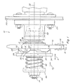
- Figure 1 shows a jaw clutch 10 including a shock damper 12 constructed and operable according to the present invention in a system in co-operation with the other components of the clutch for damping and dissipating axial force loads resulting from rapid engagement of clutch 10 and ratcheting action thereof under overrunning conditions.
- Jaw clutch 10 is of a common commercially available type for transmitting power between two rotatable members, here including an elongate rotatable shaft 14 and a rotatable sprocket 16, although it should be understood that it is contemplated that the present invention has utility for use with a wide variety of other rotatable members, including, but not limited to, pulleys or sheaves, other shafts, rollers, and the like.
- sprocket 16 is partially encircled and rotated by a roller drive chain, represented by a conventional chain link 18, rotated by a motor, engine, or other drive means (not shown), in the conventional well known manner.
- Jaw clutch 10 is mounted on shaft 14 and is automatically operable under normal conditions for connecting shaft 14 in rotatably driven relation to sprocket 16.
- Shaft 14 can be rotated for performing any useful function, such as, but not limited to, rotating components within a feeder house 20 of an agricultural combine, such as drive sprockets (not shown) of a feeder chain arrangement (also not shown).
- shaft 14 is supported in a well known manner on feeder house 20 by a plurality of bearings, represented by bearing 22 seated in a bearing housing 24 bolted or otherwise suitably mounted on a side of feeder house 20 as shown.
- Feeder house 20 is representative of feeder houses used for conveying harvested crop from a header of an agricultural combine to threshing apparatus thereof, and typically includes several endless parallel chains spanned by slats which push or convey the crop material upwardly along a bottom surface of the feeder house into an inlet region of the threshing apparatus. From time to time, wads of crop material, brush, weeds, and other items, may be conveyed through the feeder house so as to slow or stall rotation of shaft 14.
- clutch 12 is automatically disengageable to allow rotation of sprocket 16 relative to shaft 14 until the slowdown or stall condition is remedied or alleviated.
- clutch 10 includes a pair of clutch plates, including a first clutch plate 26 and a second clutch plate 28.
- Clutch plates 26 and 28 are disk shape members each having four axially extending teeth 30 at equally angularly spaced locations around a rotational axis 32.
- Clutch plates 26 and 28 are mirror images of each other and are disposed such that teeth 30 thereof are axially opposing.
- Opposing teeth 30 are matingly engageable as shown for joint rotation of clutch plates 26 and 28 about a rotational axis 32 therethrough, opposing teeth 30 being disengageable to allow relative rotation of clutch plates 26 and 28 in the well known manner.
- First clutch plate 26 is supported about shaft 14 for rotation therewith and movement along an axial path, denoted by arrow A, on a support 34 having an internally splined hole therethrough which receives and is axially movable along an externally splined portion of shaft 14 in the well known manner.
- Second clutch plate 28 is supported for joint rotation with sprocket 16 about axis 32 relative to shaft 14, on a suitable rotatable member which is preferably a bushing 36 rotatable about shaft 14 at a fixed axial position therealong.
- the axial position of bushing 36 can be fixed in any suitable conventional manner, such as by abutment with a shoulder around shaft 14.
- Bushing 36 includes an annular shoulder 38 therearound at an axially fixed location, and a backing washer 40 which axially abuts sprocket 16 opposite second clutch plate 28.
- Shock damper 12 of the present invention is preferably an annular disk spring which extends around bushing 36 between shoulder 38 and backing washer 40.
- shock damper 12 serves as a substantially rigid member or spacer which, when opposing teeth 30 of clutch plates 26 and 28 are matingly engaged for joint rotation, holds sprocket 16 and clutch plate 28 at a substantially stationary axial position on shaft 14, as shown.
- a resiliently yieldable clutch spring 42 is disposed about shaft 14 between support 34 and a spring retainer 44.
- Retainer 44 is held in position on shaft 14 by a nut 46 threadedly engaged with shaft 14 and tightenable for compressing clutch spring 42 to a desired extent for exerting a spring force, denoted by arrow F S , against support 34.
- Clutch spring 42 will have a spring rate sufficient to exert a spring force F S of sufficient magnitude to urge first clutch plate 26 against second clutch plate 28, for holding opposing teeth 30 in mating engagement for the joint rotation of clutch plates 26 and 28, denoted by arrows B and C, such that shaft 14 connected to clutch plate 26 will be drivingly rotated by sprocket 16 connected to clutch plate 28, under anticipated normal load conditions.
- clutch spring 42 should allow clutch plate 26 to move away from clutch plate 28 to allow ratcheting movement of opposing teeth 30 when a disengagement force of a desired magnitude denoted by arrow F D ( Figure 3) in opposition to spring fore F S , is exerted against the clutch plates, for instance, as a result of a high torque condition resulting from opposition to rotation of clutch plate 26 such as due to the conditions described above, namely, the presence of wads of crop material, weeds, and other items in the feeder house, or other conditions, that would slow or stall rotation of shaft 14 and/or potentially damage the rotating components or cause other damage.
- shock damper 12 of the present invention should be sufficiently rigid so as to be capable of holding sprocket 16 and clutch plate 28 substantially stationary in the axial direction when anticipated routine spring forces F S and disengagement forces F D are exerted thereagainst. Additionally, and importantly, shock damper 12 should be resiliently yieldable under substantially higher loads, so as to be capable of absorbing at least a substantial amount of axial shock forces exerted against clutch plate 28 as a result of mating reengagement of the teeth of the clutch plates during rapid ratcheting movement thereof, and function as part of a system in co-operation with other components of clutch 10 to dissipate the energy of the shock forces over a limited or predictable time, while still holding clutch plate 28 and sprocket 16 substantially axially stationary, which for the purposes of the present invention includes allowing only very limited axial movement thereof, such that operation thereof is not impaired, and the potential for shock caused damage to components carried on shaft 14, including sprocket 16, the chain, bearing 22, and the chains in feeder house 20, is significantly reduced, compared
- Such axial shock forces for the present application for driving the chain drive of feeder house 20 have been measured to have a value of as much as 10,000 pounds (44 500 N).
- limited axial movement what is meant is an amount of axial movement sufficiently small such that impairment of the operation of, and damage to, the rotatable members will not occur as a result of the movement.
- the shock damper 12 should have the ability to dampen the 10,000 pound (44 500 N) shock force and dissipate the energy thereof over a time interval or period less than that before the occurrence of the next shock force as a result of ratcheting over another tooth.
- clutch plates 26 and 28 each have 4 teeth at equally spaced locations therearound, the time period between the occurrence of the shock forces will be equal to that for the clutch plates to relatively rotate about 1/4 revolution, which for the normal operating speed of the present feeder drive application can be just a few hundredths of a second, for instance, about 0.02 second.
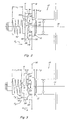
- FIG. 2 is a simplified schematic representation of jaw clutch 10 for the present application, showing a disk spring shock force damper 12, shaft 14, sprocket 16 and clutch spring 42 which is a single compression coil spring.
- Clutch spring 42 is shown at its normal or initial axial length L 1 .
- Shock force damper 12 is shown at its normal or initial axial length L 2 .
- clutch plates 26 and 28 are fully engaged by the exertion of spring force F S against support 34 with shock force damper 12 disposed in contact with backing washer 40 supporting sprocket 16 and second clutch plate 28, for rotation of clutch plate 26 by clutch plate 28, as denoted by arrows B and C.
- the axial height of opposing teeth 30 is also shown, as denoted by dimension H.
- H will have a value of about 0.25 inch (6.35 mm). It should be noted that adjacent ones of matingly engaged sets of teeth of clutch plates 26 and 28 are separated by spaces 48. Each set of the matingly engaged teeth 30 have opposing ramp surfaces 50 in abutting relation and through which the rotational driving force is transferred from the driving clutch plate, here clutch plate 28, to the driven clutch plate, here clutch plate 26. Surfaces 50 are each preferably oriented at about a 50 to 60 degree angle to the direction of rotation denoted by arrows B and C, although it should be understood that other angles for ramp surfaces 50, including perpendicular to the rotational direction, and other height values H for teeth 30, can be used, as required or desired for a particular application.
- clutch 10 is shown with clutch plates 26 and 28 held apart by sliding engagement of axially opposing surfaces 52 of teeth 30 as clutch plate 28 and sprocket 16 rotate or ratchet jointly relative to clutch plate 26, as denoted by arrow B.
- Clutch spring 42 is still displaced by the amount H and damper 12 is still at its initial length L 2 .
- Opposing forces F S and F D are still present, the energy thereof being stored as potential energy in spring 42.
- teeth 30 of clutch plate 28 are shown rotated past teeth 30 of clutch plate 26 such that the clutch plates are no longer held apart thereby.
- teeth 30 of clutch plate 28 are rotating in the direction B relative to teeth 30 of clutch plate 26, even if back surfaces 54 of opposing teeth 30 are briefly engaged, little or none of disengagement force F D will be exerted therebetween to force the clutch plates apart. Instead, the stored potential energy of spring 42 is suddenly released, as denoted by arrow PE, to drive clutch plate 26 rapidly toward clutch plate 28, as denoted by arrow A.
- shock damper 12 is a disk spring, when it absorbs the energy and is resultantly deformed, some of the deformation will be in the diameter and shape thereof in addition to in the length thereof, such that axial displacement D and thus axial movement of clutch plate 28 and sprocket 16 can be minimised. Shock damper 12 will then release the absorbed energy such that the energy will be at least partially dissipated by cooperative movements of clutch spring 42 and clutch plates 26 and 28, and, as a result the magnitude of shock forces or loads S2 transferred to shaft 14 will be damped and much lower than the magnitude of the initial shock force S1.
- shock force damper 12 and clutch spring 42 should be selected so as to provide a desired torque transferring capability required for a particular application while maintaining sprocket 16 at a substantially stationary axial position on shaft 14, and such that shock damper 12 will absorb a useful amount of the energy of anticipated shock forces, and further such that shock force damper 12, clutch plates 26 and 28, and clutch spring 42 will co-operate to dissipate a substantial portion of the shock force energy to substantially lower the magnitude of resultant shock forces or loads S2 transferred to shaft 14.
- the spring rate of the disk spring should be at least ten times greater than the spring rate of the clutch spring. More preferably, the spring rate of the disk spring is at least fifteen times greater than the spring rate of the clutch spring.
- a range of suitable values for the spring rate of the disk spring can be between about 30,000 pounds per inch (5,255 N/mm) and about 40,000 pounds per inch (7,005 N/mm) and the spring rate of the clutch spring between about 2,000 pounds per inch (350 N/mm) and about 3,000 pounds per inch (525 N/mm). More specifically, a satisfactory spring rate of the disk spring is about 36,800 pounds per inch (6,447 N/mm) and the spring rate for the clutch spring about 2,235 pounds per inch (392 N/mm).
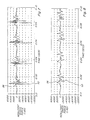
- FIG 7 a graphical representation of resultant shock force measured on shaft 14 versus time for ratcheting operation of jaw clutch 10 without shock force damper 12.
- Positive force measurements reflect forces exerted in the direction to compress clutch spring 42 and negative force values reflect shock forces resulting from release of stored energy.
- peak 56 reflects axial force on shaft 14 as disengagement force F D is applied for matingly disengaging the teeth of clutch plates 26 and 28, and negative peak 58 reflects the initial axial shock force exerted against shaft 14 when the teeth are abruptly matingly re-engaged.
- the magnitude of the disengagement force represented by peak 56 is about 2,000 pounds (8,900 N).
- the magnitude of the shock force at peak 58 is about 10,000 pounds (44,500 N).
- Subsequent forces resulting from the re-engagement have magnitudes of more than 6,000 pounds (26,700 N). This pattern is repeated at about 0.02 second intervals.
- Figure 8 shows resultant axial shock forces exerted against shaft 14 with shock force damper 12 installed on jaw clutch 10 as described above.
- the axial force exerted against shaft 14 by the disengagement force F D still has a maximum value as denoted at peak 56 of about 2,000 pounds (8,900 N).
- the maximum shock force exerted against shaft 14 is less than 4,000 pounds (17,800 N), as denoted by peak 60.
- peak 60 This is also true of the subsequent ratcheting actions at about the same time intervals as shown in Figure 7 throughout a span of about 0.10 second.
- resultant axial shock forces exerted against shaft 14 are reduced by at least half, and by as much as 60% or more.
- occurrence of resultant damage to components thereof is correspondingly reduced.
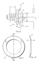
- Figures 9 and 10 are an end view and a sectional view of shock force damper 12.
- shock force damper 12 is an annular disk spring having a frusto-conical shape, including a larger diameter end 62 which is positioned to abut and bear against backing washer 40, and an opposite smaller diameter end 64 that is positioned in abutment with shoulder 38 of bushing 36, both as shown in Figure 1.
- the disk spring of shock force damper 12 will have a spring rate at least several times greater than that of clutch spring 44, to provide the shock force damping capability as graphically illustrated in Figure 8.
- the disk spring resiliently flattens in the axial direction and deforms in shape, the disk spring having memory properties so as to return to its original shape after removal or reduction of the force.
- a jaw clutch including means for absorbing shock forces resulting from engagement of the clutch and dissipating the forces over time in co-operation with other components of the clutch for damping or reducing the intensity and magnitude of resultant forces exerted against the rotating members.
Landscapes
- Engineering & Computer Science (AREA)
- General Engineering & Computer Science (AREA)
- Mechanical Engineering (AREA)
- Mechanical Operated Clutches (AREA)
Claims (10)
- Landwirtschaftliche Erntemaschine mit einem Antriebsstrang, der eine Klauenkupplung (10) zur Übertragung von Drehantriebsleistung von einem antreibenden drehbaren Element (16) auf ein angetriebenes drehbares Element (14) umfasst, wobei die Klauenkupplung Folgendes umfasst:eine erste Kupplungsplatte (26), die mit einem (14) der drehbaren Elemente für eine Drehung mit diesem verbunden und für eine Bewegung entlang eines vorgegebenen Pfades (A) gegenüber dem einen drehbaren Element (14) befestigt ist;eine zweite Kupplungsplatte (28), die mit dem anderen (16) der drehbaren Elemente für eine Drehung mit diesem benachbart zu einem Ende des Pfades (A) verbunden ist, wobei die ersten und zweiten Kupplungsplatten (26, 28) Zähne (30) einschließen, die in Passeingriff bringbar sind, wenn die erste Kupplungsplatte (26) zu dem Ende des Pfades (A) hin bewegt wird, um die Kupplungsplatten (26, 28) für eine gemeinsame Drehung miteinander zu verbinden; undeine Kupplungsfeder (42), die zum Ausüben einer Federkraft (FS)gegen die erste Kupplungsplatte (26) angeordnet ist, um die erste Kupplungsplatte (26) an dem Ende des Pfades (A) benachbart zu der zweiten Kupplungsplatte (28) zu halten, wobei die Kupplungsfeder (42) bei einer Auskuppel-Kraft (FD) nachgibt, die größer als die und entgegengesetzt zu der Federkraft (FS) ist, derart, dass die erste Kupplungsplatte (26) entlang des Pfades (A) von der zweiten Kupplungsplatte (28) fort bewegt wird, und die Zähne (30) der Kupplungsplatte, die mit dem antriebsmäßig in Drehung versetzten Element (16) verbunden ist, sich in einer Ratschenwirkung über die Zähne (30) der Kupplungsplatte (26) bewegen, die mit dem angetriebenen drehbaren Element (14) verbunden ist, um Stoßkräfte zwischen den Kupplungsplatten zu erzeugen, die Amplituden aufweisen, die beträchtlich größer als die Amplitude der Auskuppel-Kraft (FD) in Zeitintervallen sind, die eine Funktion der relativen Drehgeschwindigkeiten der Kupplungsplatten (26, 28) sind,dadurch gekennzeichnet, dass:die Klauenkupplung (10) weiterhin eine elastisch verformbare Dämpfungsfeder (12) umfasst, die in Verbindung mit der zweiten Kupplungsplatte (28) angeordnet ist, um einen erheblichen Teil der Energie der Stoßkräfte zu absorbieren, die zwischen den Kupplungsplatten erzeugt werden, und dann diese Energie freizugeben, so dass sie zumindest teilweise durch die Kupplung (12) verbraucht wird, derart, dass die resultierenden Teile der Stoßkräfte, die gegen die rotierenden Elemente (14, 16) ausgeübt werden, so gedämpft werden, dass sie maximale Amplituden (60) haben, die kleiner als die Hälfte der Amplituden der Stoßkräfte sind, die zwischen den Kupplungsplatten erzeugt werden, während die zweite Kupplungsplatte (28) im Wesentlichen stationär benachbart zu dem Ende des Pfades (A) gehalten wird;die Dämpfungsfeder (12) elastisch von einer Anfangsform auf eine verformte Form durch Absorbieren der Energie der Stoßkräfte verformbar ist und auf die anfängliche Form durch Freigeben der durch sie absorbierten Energie zurückkehrt; unddie Dämpfungsfeder (12) eine vorgegebene Federkonstante hat, die mehrere Male größer als die Federkonstante der Kupplungsfeder (42) ist, so dass die Dämpfungsfeder die anfängliche Form beibehält, wenn die Energie der Stoßkraft nicht vorhanden ist.
- Landwirtschaftliche Erntemaschine nach Anspruch 1, dadurch gekennzeichnet, dass die Dämpfungsfeder (12) im Zusammenwirken mit der Kupplungsfeder (42) betreibbar ist, um zyklisch zumindest einen Teil der Energie der Stoßkraft zwischen den Kupplungsplatten (26, 28) zum Verbrauch der Energie zu übertragen.
- Landwirtschaftliche Erntemaschine nach Anspruch 1 oder 2, dadurch gekennzeichnet, dass die Federkonstante der Dämpfungsfeder (12) zumindest zehnmal größer als die Federkonstante der Kupplungsfeder (42) ist.
- Landwirtschaftliche Erntemaschine nach Anspruch 3, dadurch gekennzeichnet, dass die Federkonstante der Dämpfungsfeder (12) zumindest fünfzehnmal größer als die Federkonstante der Kupplungsfeder (42) ist.
- Landwirtschaftliche Erntemaschine nach Anspruch 3, dadurch gekennzeichnet, dass die Federkonstante der Dämpfungsfeder (12) zwischen ungefähr 5255 N/mm und ungefähr 7000 N/mm liegt, und das die Federkonstante der Kupplungsfeder (42) zwischen ungefähr 350 und ungefähr 525 N/mm liegt.
- Landwirtschaftliche Erntemaschine nach Anspruch 5, dadurch gekennzeichnet, dass die Federkonstante der Dämpfungsfeder (12) zwischen ungefähr 6100 N/mm und 6660 N/mm liegt und die Federkonstante der Kupplungsfeder (42) zwischen ungefähr 370 und ungefähr 420 N/mm liegt.
- Landwirtschaftliche Erntemaschine nach einem der Ansprüche 1 bis 6, dadurch gekennzeichnet, dass die Dämpfungsfeder eine ringförmige Scheibenfeder (12) ist.
- Landwirtschaftliche Erntemaschine nach einem der vorhergehenden Ansprüche, dadurch gekennzeichnet, dass:die zweite Kupplungsplatte (28) und das damit verbundene drehbare Element (16) auf einer Hülse (36) befestigt sind, die auf dem drehbaren Element (14 in fester Beziehung zu dem Ende des Pfades (A) gelagert ist und eine Schulter (38) einschließt, die sich um diese herum erstreckt; unddie Dämpfungsfeder 812) zwischen dem drehbaren Element (16), das mit der zweiten Kupplungsplatte (28) verbunden ist, und der Schulter (38) angeordnet ist.
- Landwirtschaftliche Erntemaschine nach einem der vorhergehenden Ansprüche, dadurch gekennzeichnet, dass das drehbare Element, das mit der ersten Kupplungsplatte (26) verbunden ist, eine drehbare Welle (14) ist, und dass die Bewegung der ersten Kupplungsplatte (26) entlang eines vorgegebenen Pfades (A) eine axiale Bewegung entlang der Welle ist.
- Landwirtschaftliche Erntemaschine nach einem der vorhergehenden Ansprüche, dadurch gekennzeichnet, dass der Antriebsstrang für den Drehantrieb von Bauteilen in einem Zuführungsgehäuse (20) vorgesehen ist.
Applications Claiming Priority (2)
| Application Number | Priority Date | Filing Date | Title |
|---|---|---|---|
| US722744 | 2003-11-25 | ||
| US10/722,744 US6979268B2 (en) | 2003-11-25 | 2003-11-25 | Jaw clutch shock force damper system |
Publications (2)
| Publication Number | Publication Date |
|---|---|
| EP1536155A1 EP1536155A1 (de) | 2005-06-01 |
| EP1536155B1 true EP1536155B1 (de) | 2008-01-23 |
Family
ID=34465693
Family Applications (1)
| Application Number | Title | Priority Date | Filing Date |
|---|---|---|---|
| EP04105867A Expired - Lifetime EP1536155B1 (de) | 2003-11-25 | 2004-11-18 | Stossdämpfersystem für Klauenkupplung |
Country Status (4)
| Country | Link |
|---|---|
| US (1) | US6979268B2 (de) |
| EP (1) | EP1536155B1 (de) |
| AT (1) | ATE384886T1 (de) |
| DE (1) | DE602004011451T2 (de) |
Families Citing this family (8)
| Publication number | Priority date | Publication date | Assignee | Title |
|---|---|---|---|---|
| JP4497040B2 (ja) * | 2005-07-08 | 2010-07-07 | 日立工機株式会社 | 振動ドリル |
| US8615821B2 (en) * | 2007-05-31 | 2013-12-31 | Zurn Industries, Llc | Actuator having a clutch assembly |
| DE202007018579U1 (de) * | 2007-09-21 | 2008-12-11 | Claas Saulgau Gmbh | Mähmaschine |
| DE102009015822B3 (de) * | 2009-04-01 | 2011-04-07 | Metabowerke Gmbh | Heckenschere |
| CN102764511B (zh) * | 2011-05-06 | 2016-05-11 | 德昌电机(深圳)有限公司 | 驱动装置 |
| US10098285B2 (en) * | 2015-02-25 | 2018-10-16 | Chervon (Hk) Limited | Gardening tool and hedge trimmer |
| JP6852808B2 (ja) * | 2017-10-31 | 2021-03-31 | 工機ホールディングス株式会社 | 動力工具 |
| DE102021119512B4 (de) | 2021-07-28 | 2025-03-06 | Karl Storz Se & Co. Kg | Roboterarm mit einer Freilaufkupplung zum Begrenzen eines übertragbaren Drehmomentes an einer rotierenden Antriebsachse eines Endeffektors eines Roboters sowie Roboter |
Family Cites Families (19)
| Publication number | Priority date | Publication date | Assignee | Title |
|---|---|---|---|---|
| DE437803C (de) * | 1925-07-22 | 1926-11-29 | Siemens Schuckertwerke G M B H | Sicherheitskupplung |
| US2291407A (en) * | 1939-05-06 | 1942-07-28 | Deere & Co | Slip clutch |
| US2348717A (en) | 1942-01-05 | 1944-05-16 | New Prod Corp | Quiet-ratcheting jaw clutch |
| US2751740A (en) * | 1953-05-11 | 1956-06-26 | Allis Chalmers Mfg Co | Elevator drive means for corn harvesters |
| DE1046418B (de) * | 1953-06-11 | 1958-12-11 | Frieda Gaunitz Geb Bittdorf | Elastische Rutschkupplung |
| US2869697A (en) | 1954-08-18 | 1959-01-20 | Tiltman Langley Ltd | Power transmission clutch |
| US2869700A (en) | 1954-11-19 | 1959-01-20 | Gen Electric | Positive clutch with damping arrangement |
| US3314257A (en) | 1965-02-04 | 1967-04-18 | Gen Motors Corp | Clothes washing machine with a slipping clutch |
| NL6510026A (de) * | 1965-08-03 | 1967-02-06 | ||
| US3491602A (en) | 1968-01-25 | 1970-01-27 | Meter All Mfg Co Inc | Switch actuating apparatus |
| DE1945002A1 (de) * | 1969-09-05 | 1971-03-11 | Siemens Elektrogeraete Gmbh | Riementrieb |
| US3934688A (en) | 1974-09-11 | 1976-01-27 | The Black And Decker Manufacturing Company | Shifter mechanism |
| US3942337A (en) * | 1974-09-16 | 1976-03-09 | Industrial Analytics Inc. | Torque limiting device |
| CA1091054A (en) | 1976-05-13 | 1980-12-09 | Frank R. Burgener, Jr. | One-way clutch for auger agitator |
| CH654632A5 (de) | 1981-07-10 | 1986-02-28 | Maag Zahnraeder & Maschinen Ag | Selbsttaetig einrueckbare zahnkupplung. |
| GB8923325D0 (en) * | 1989-10-17 | 1989-12-06 | Smiths Industries Plc | Locking mechanisms |
| DE19629618A1 (de) | 1996-07-23 | 1998-01-29 | Claas Ohg | Routenplanungssystem für landwirtschaftliche Arbeitsfahrzeuge |
| DE19847405C1 (de) | 1998-10-14 | 2000-07-20 | Gkn Viscodrive Gmbh | Schaltkupplung |
| DE10162561A1 (de) * | 2001-12-19 | 2003-07-17 | Siemens Ag | Kupplung |
-
2003
- 2003-11-25 US US10/722,744 patent/US6979268B2/en not_active Expired - Lifetime
-
2004
- 2004-11-18 DE DE602004011451T patent/DE602004011451T2/de not_active Expired - Lifetime
- 2004-11-18 EP EP04105867A patent/EP1536155B1/de not_active Expired - Lifetime
- 2004-11-18 AT AT04105867T patent/ATE384886T1/de not_active IP Right Cessation
Also Published As
| Publication number | Publication date |
|---|---|
| US6979268B2 (en) | 2005-12-27 |
| DE602004011451T2 (de) | 2008-04-30 |
| EP1536155A1 (de) | 2005-06-01 |
| DE602004011451D1 (de) | 2008-03-13 |
| US20050113175A1 (en) | 2005-05-26 |
| ATE384886T1 (de) | 2008-02-15 |
Similar Documents
| Publication | Publication Date | Title |
|---|---|---|
| KR101258825B1 (ko) | 마찰형 감쇠를 가지는 회전 원웨이 클러치 체인 텐셔너 | |
| KR101558117B1 (ko) | 교류 발전기 격리 디커플러 | |
| US8272982B2 (en) | Cam damped pulley for rotary devices | |
| US4566570A (en) | Overload clutch | |
| EP1536155B1 (de) | Stossdämpfersystem für Klauenkupplung | |
| CA2155587C (en) | Belt transmission method and belt transmission device | |
| US7059982B2 (en) | Utility machinery and associated control arrangements | |
| US20120103743A1 (en) | Spatial wedging friction overrunning clutch | |
| US4913681A (en) | Shock absorbing rotary gear coupling | |
| US11976694B2 (en) | Power take off including a torsional vibration damping assembly | |
| JP6303070B2 (ja) | 貯蔵エネルギー及び減衰特徴を有する回転式テンショナー | |
| EP1969255A1 (de) | Zugmitteltrieb für eine brennkraftmaschine | |
| US4508213A (en) | Hydraulic take-up device | |
| US4605386A (en) | Compact variable speed pulley assembly | |
| US20130319814A1 (en) | Clutched device with thrust ring | |
| CN211202792U (zh) | 一种带离合保护装置的齿轮箱 | |
| US20060276282A1 (en) | Utility machinery and associated control arrangements | |
| US9879735B2 (en) | Shear pin | |
| EP2533624A1 (de) | Aufsatz einer erntemaschine | |
| RU20699U1 (ru) | Фрезерная почвообрабатывающая машина | |
| RU22516U1 (ru) | Упругая муфта | |
| SU1164481A1 (ru) | Предохранительная·муфта в.п.черных |
Legal Events
| Date | Code | Title | Description |
|---|---|---|---|
| PUAI | Public reference made under article 153(3) epc to a published international application that has entered the european phase |
Free format text: ORIGINAL CODE: 0009012 |
|
| AK | Designated contracting states |
Kind code of ref document: A1 Designated state(s): AT BE BG CH CY CZ DE DK EE ES FI FR GB GR HU IE IS IT LI LU MC NL PL PT RO SE SI SK TR |
|
| AX | Request for extension of the european patent |
Extension state: AL HR LT LV MK YU |
|
| 17P | Request for examination filed |
Effective date: 20051114 |
|
| AKX | Designation fees paid |
Designated state(s): AT BE BG CH CY CZ DE DK EE ES FI FR GB GR HU IE IS IT LI LU MC NL PL PT RO SE SI SK TR |
|
| GRAP | Despatch of communication of intention to grant a patent |
Free format text: ORIGINAL CODE: EPIDOSNIGR1 |
|
| GRAS | Grant fee paid |
Free format text: ORIGINAL CODE: EPIDOSNIGR3 |
|
| GRAA | (expected) grant |
Free format text: ORIGINAL CODE: 0009210 |
|
| AK | Designated contracting states |
Kind code of ref document: B1 Designated state(s): AT BE BG CH CY CZ DE DK EE ES FI FR GB GR HU IE IS IT LI LU MC NL PL PT RO SE SI SK TR |
|
| REG | Reference to a national code |
Ref country code: GB Ref legal event code: FG4D |
|
| REG | Reference to a national code |
Ref country code: CH Ref legal event code: EP |
|
| REG | Reference to a national code |
Ref country code: IE Ref legal event code: FG4D |
|
| REF | Corresponds to: |
Ref document number: 602004011451 Country of ref document: DE Date of ref document: 20080313 Kind code of ref document: P |
|
| NLV1 | Nl: lapsed or annulled due to failure to fulfill the requirements of art. 29p and 29m of the patents act | ||
| PG25 | Lapsed in a contracting state [announced via postgrant information from national office to epo] |
Ref country code: CH Free format text: LAPSE BECAUSE OF FAILURE TO SUBMIT A TRANSLATION OF THE DESCRIPTION OR TO PAY THE FEE WITHIN THE PRESCRIBED TIME-LIMIT Effective date: 20080123 Ref country code: ES Free format text: LAPSE BECAUSE OF FAILURE TO SUBMIT A TRANSLATION OF THE DESCRIPTION OR TO PAY THE FEE WITHIN THE PRESCRIBED TIME-LIMIT Effective date: 20080504 Ref country code: IS Free format text: LAPSE BECAUSE OF FAILURE TO SUBMIT A TRANSLATION OF THE DESCRIPTION OR TO PAY THE FEE WITHIN THE PRESCRIBED TIME-LIMIT Effective date: 20080523 Ref country code: FI Free format text: LAPSE BECAUSE OF FAILURE TO SUBMIT A TRANSLATION OF THE DESCRIPTION OR TO PAY THE FEE WITHIN THE PRESCRIBED TIME-LIMIT Effective date: 20080123 Ref country code: LI Free format text: LAPSE BECAUSE OF FAILURE TO SUBMIT A TRANSLATION OF THE DESCRIPTION OR TO PAY THE FEE WITHIN THE PRESCRIBED TIME-LIMIT Effective date: 20080123 |
|
| REG | Reference to a national code |
Ref country code: CH Ref legal event code: PL |
|
| ET | Fr: translation filed | ||
| PG25 | Lapsed in a contracting state [announced via postgrant information from national office to epo] |
Ref country code: BG Free format text: LAPSE BECAUSE OF FAILURE TO SUBMIT A TRANSLATION OF THE DESCRIPTION OR TO PAY THE FEE WITHIN THE PRESCRIBED TIME-LIMIT Effective date: 20080423 Ref country code: AT Free format text: LAPSE BECAUSE OF FAILURE TO SUBMIT A TRANSLATION OF THE DESCRIPTION OR TO PAY THE FEE WITHIN THE PRESCRIBED TIME-LIMIT Effective date: 20080123 |
|
| PG25 | Lapsed in a contracting state [announced via postgrant information from national office to epo] |
Ref country code: PT Free format text: LAPSE BECAUSE OF FAILURE TO SUBMIT A TRANSLATION OF THE DESCRIPTION OR TO PAY THE FEE WITHIN THE PRESCRIBED TIME-LIMIT Effective date: 20080623 Ref country code: BE Free format text: LAPSE BECAUSE OF FAILURE TO SUBMIT A TRANSLATION OF THE DESCRIPTION OR TO PAY THE FEE WITHIN THE PRESCRIBED TIME-LIMIT Effective date: 20080123 Ref country code: SI Free format text: LAPSE BECAUSE OF FAILURE TO SUBMIT A TRANSLATION OF THE DESCRIPTION OR TO PAY THE FEE WITHIN THE PRESCRIBED TIME-LIMIT Effective date: 20080123 Ref country code: PL Free format text: LAPSE BECAUSE OF FAILURE TO SUBMIT A TRANSLATION OF THE DESCRIPTION OR TO PAY THE FEE WITHIN THE PRESCRIBED TIME-LIMIT Effective date: 20080123 |
|
| PG25 | Lapsed in a contracting state [announced via postgrant information from national office to epo] |
Ref country code: SE Free format text: LAPSE BECAUSE OF FAILURE TO SUBMIT A TRANSLATION OF THE DESCRIPTION OR TO PAY THE FEE WITHIN THE PRESCRIBED TIME-LIMIT Effective date: 20080423 Ref country code: NL Free format text: LAPSE BECAUSE OF FAILURE TO SUBMIT A TRANSLATION OF THE DESCRIPTION OR TO PAY THE FEE WITHIN THE PRESCRIBED TIME-LIMIT Effective date: 20080123 Ref country code: DK Free format text: LAPSE BECAUSE OF FAILURE TO SUBMIT A TRANSLATION OF THE DESCRIPTION OR TO PAY THE FEE WITHIN THE PRESCRIBED TIME-LIMIT Effective date: 20080123 Ref country code: SK Free format text: LAPSE BECAUSE OF FAILURE TO SUBMIT A TRANSLATION OF THE DESCRIPTION OR TO PAY THE FEE WITHIN THE PRESCRIBED TIME-LIMIT Effective date: 20080123 Ref country code: CZ Free format text: LAPSE BECAUSE OF FAILURE TO SUBMIT A TRANSLATION OF THE DESCRIPTION OR TO PAY THE FEE WITHIN THE PRESCRIBED TIME-LIMIT Effective date: 20080123 |
|
| PG25 | Lapsed in a contracting state [announced via postgrant information from national office to epo] |
Ref country code: RO Free format text: LAPSE BECAUSE OF FAILURE TO SUBMIT A TRANSLATION OF THE DESCRIPTION OR TO PAY THE FEE WITHIN THE PRESCRIBED TIME-LIMIT Effective date: 20080123 |
|
| PLBE | No opposition filed within time limit |
Free format text: ORIGINAL CODE: 0009261 |
|
| STAA | Information on the status of an ep patent application or granted ep patent |
Free format text: STATUS: NO OPPOSITION FILED WITHIN TIME LIMIT |
|
| 26N | No opposition filed |
Effective date: 20081024 |
|
| PG25 | Lapsed in a contracting state [announced via postgrant information from national office to epo] |
Ref country code: EE Free format text: LAPSE BECAUSE OF FAILURE TO SUBMIT A TRANSLATION OF THE DESCRIPTION OR TO PAY THE FEE WITHIN THE PRESCRIBED TIME-LIMIT Effective date: 20080123 |
|
| PG25 | Lapsed in a contracting state [announced via postgrant information from national office to epo] |
Ref country code: MC Free format text: LAPSE BECAUSE OF NON-PAYMENT OF DUE FEES Effective date: 20081130 |
|
| PG25 | Lapsed in a contracting state [announced via postgrant information from national office to epo] |
Ref country code: CY Free format text: LAPSE BECAUSE OF FAILURE TO SUBMIT A TRANSLATION OF THE DESCRIPTION OR TO PAY THE FEE WITHIN THE PRESCRIBED TIME-LIMIT Effective date: 20080123 |
|
| PG25 | Lapsed in a contracting state [announced via postgrant information from national office to epo] |
Ref country code: IE Free format text: LAPSE BECAUSE OF NON-PAYMENT OF DUE FEES Effective date: 20081118 |
|
| PG25 | Lapsed in a contracting state [announced via postgrant information from national office to epo] |
Ref country code: HU Free format text: LAPSE BECAUSE OF FAILURE TO SUBMIT A TRANSLATION OF THE DESCRIPTION OR TO PAY THE FEE WITHIN THE PRESCRIBED TIME-LIMIT Effective date: 20080724 Ref country code: LU Free format text: LAPSE BECAUSE OF NON-PAYMENT OF DUE FEES Effective date: 20081118 |
|
| PG25 | Lapsed in a contracting state [announced via postgrant information from national office to epo] |
Ref country code: TR Free format text: LAPSE BECAUSE OF FAILURE TO SUBMIT A TRANSLATION OF THE DESCRIPTION OR TO PAY THE FEE WITHIN THE PRESCRIBED TIME-LIMIT Effective date: 20080123 |
|
| PG25 | Lapsed in a contracting state [announced via postgrant information from national office to epo] |
Ref country code: GR Free format text: LAPSE BECAUSE OF FAILURE TO SUBMIT A TRANSLATION OF THE DESCRIPTION OR TO PAY THE FEE WITHIN THE PRESCRIBED TIME-LIMIT Effective date: 20080424 |
|
| REG | Reference to a national code |
Ref country code: DE Ref legal event code: R082 Ref document number: 602004011451 Country of ref document: DE Representative=s name: PATENTANWAELTE WALLACH, KOCH & PARTNER, DE |
|
| REG | Reference to a national code |
Ref country code: DE Ref legal event code: R082 Ref document number: 602004011451 Country of ref document: DE Representative=s name: PATENTANWAELTE WALLACH, KOCH & PARTNER, DE Effective date: 20140428 Ref country code: DE Ref legal event code: R082 Ref document number: 602004011451 Country of ref document: DE Representative=s name: PATENTANWAELTE WALLACH, KOCH, DR. HAIBACH, FEL, DE Effective date: 20140428 Ref country code: DE Ref legal event code: R081 Ref document number: 602004011451 Country of ref document: DE Owner name: CNH INDUSTRIAL BELGIUM NV, BE Free format text: FORMER OWNER: CNH BELGIUM NV, ZEDELGEM, BE Effective date: 20140428 |
|
| REG | Reference to a national code |
Ref country code: FR Ref legal event code: CD Owner name: CNH INDUSTRIAL BELGIUM NV Effective date: 20140725 |
|
| REG | Reference to a national code |
Ref country code: FR Ref legal event code: PLFP Year of fee payment: 12 |
|
| REG | Reference to a national code |
Ref country code: FR Ref legal event code: PLFP Year of fee payment: 13 |
|
| REG | Reference to a national code |
Ref country code: FR Ref legal event code: PLFP Year of fee payment: 14 |
|
| REG | Reference to a national code |
Ref country code: FR Ref legal event code: PLFP Year of fee payment: 15 |
|
| PGFP | Annual fee paid to national office [announced via postgrant information from national office to epo] |
Ref country code: GB Payment date: 20181031 Year of fee payment: 9 Ref country code: FR Payment date: 20181018 Year of fee payment: 15 |
|
| PGFP | Annual fee paid to national office [announced via postgrant information from national office to epo] |
Ref country code: DE Payment date: 20191128 Year of fee payment: 16 |
|
| PGFP | Annual fee paid to national office [announced via postgrant information from national office to epo] |
Ref country code: IT Payment date: 20191111 Year of fee payment: 16 |
|
| REG | Reference to a national code |
Ref country code: DE Ref legal event code: R082 Ref document number: 602004011451 Country of ref document: DE Representative=s name: MEISSNER BOLTE PATENTANWAELTE RECHTSANWAELTE P, DE |
|
| GBPC | Gb: european patent ceased through non-payment of renewal fee |
Effective date: 20191118 |
|
| PG25 | Lapsed in a contracting state [announced via postgrant information from national office to epo] |
Ref country code: GB Free format text: LAPSE BECAUSE OF NON-PAYMENT OF DUE FEES Effective date: 20191118 Ref country code: FR Free format text: LAPSE BECAUSE OF NON-PAYMENT OF DUE FEES Effective date: 20191130 |
|
| REG | Reference to a national code |
Ref country code: DE Ref legal event code: R119 Ref document number: 602004011451 Country of ref document: DE |
|
| PG25 | Lapsed in a contracting state [announced via postgrant information from national office to epo] |
Ref country code: IT Free format text: LAPSE BECAUSE OF NON-PAYMENT OF DUE FEES Effective date: 20201118 |
|
| PG25 | Lapsed in a contracting state [announced via postgrant information from national office to epo] |
Ref country code: DE Free format text: LAPSE BECAUSE OF NON-PAYMENT OF DUE FEES Effective date: 20210601 |