EP1536116A2 - Übertragungsvorrichtung zur Brennstoffsparung - Google Patents
Übertragungsvorrichtung zur Brennstoffsparung Download PDFInfo
- Publication number
- EP1536116A2 EP1536116A2 EP04425449A EP04425449A EP1536116A2 EP 1536116 A2 EP1536116 A2 EP 1536116A2 EP 04425449 A EP04425449 A EP 04425449A EP 04425449 A EP04425449 A EP 04425449A EP 1536116 A2 EP1536116 A2 EP 1536116A2
- Authority
- EP
- European Patent Office
- Prior art keywords
- compressed air
- impeller
- tubing
- flue gases
- saving
- Prior art date
- Legal status (The legal status is an assumption and is not a legal conclusion. Google has not performed a legal analysis and makes no representation as to the accuracy of the status listed.)
- Withdrawn
Links
Images


Classifications
-
- F—MECHANICAL ENGINEERING; LIGHTING; HEATING; WEAPONS; BLASTING
- F02—COMBUSTION ENGINES; HOT-GAS OR COMBUSTION-PRODUCT ENGINE PLANTS
- F02B—INTERNAL-COMBUSTION PISTON ENGINES; COMBUSTION ENGINES IN GENERAL
- F02B41/00—Engines characterised by special means for improving conversion of heat or pressure energy into mechanical power
- F02B41/02—Engines with prolonged expansion
- F02B41/10—Engines with prolonged expansion in exhaust turbines
-
- F—MECHANICAL ENGINEERING; LIGHTING; HEATING; WEAPONS; BLASTING
- F02—COMBUSTION ENGINES; HOT-GAS OR COMBUSTION-PRODUCT ENGINE PLANTS
- F02B—INTERNAL-COMBUSTION PISTON ENGINES; COMBUSTION ENGINES IN GENERAL
- F02B67/00—Engines characterised by the arrangement of auxiliary apparatus not being otherwise provided for, e.g. the apparatus having different functions; Driving auxiliary apparatus from engines, not otherwise provided for
-
- F—MECHANICAL ENGINEERING; LIGHTING; HEATING; WEAPONS; BLASTING
- F02—COMBUSTION ENGINES; HOT-GAS OR COMBUSTION-PRODUCT ENGINE PLANTS
- F02B—INTERNAL-COMBUSTION PISTON ENGINES; COMBUSTION ENGINES IN GENERAL
- F02B73/00—Combinations of two or more engines, not otherwise provided for
-
- F—MECHANICAL ENGINEERING; LIGHTING; HEATING; WEAPONS; BLASTING
- F02—COMBUSTION ENGINES; HOT-GAS OR COMBUSTION-PRODUCT ENGINE PLANTS
- F02B—INTERNAL-COMBUSTION PISTON ENGINES; COMBUSTION ENGINES IN GENERAL
- F02B77/00—Component parts, details or accessories, not otherwise provided for
-
- F—MECHANICAL ENGINEERING; LIGHTING; HEATING; WEAPONS; BLASTING
- F02—COMBUSTION ENGINES; HOT-GAS OR COMBUSTION-PRODUCT ENGINE PLANTS
- F02G—HOT GAS OR COMBUSTION-PRODUCT POSITIVE-DISPLACEMENT ENGINE PLANTS; USE OF WASTE HEAT OF COMBUSTION ENGINES; NOT OTHERWISE PROVIDED FOR
- F02G5/00—Profiting from waste heat of combustion engines, not otherwise provided for
- F02G5/02—Profiting from waste heat of exhaust gases
- F02G5/04—Profiting from waste heat of exhaust gases in combination with other waste heat from combustion engines
-
- Y—GENERAL TAGGING OF NEW TECHNOLOGICAL DEVELOPMENTS; GENERAL TAGGING OF CROSS-SECTIONAL TECHNOLOGIES SPANNING OVER SEVERAL SECTIONS OF THE IPC; TECHNICAL SUBJECTS COVERED BY FORMER USPC CROSS-REFERENCE ART COLLECTIONS [XRACs] AND DIGESTS
- Y02—TECHNOLOGIES OR APPLICATIONS FOR MITIGATION OR ADAPTATION AGAINST CLIMATE CHANGE
- Y02T—CLIMATE CHANGE MITIGATION TECHNOLOGIES RELATED TO TRANSPORTATION
- Y02T10/00—Road transport of goods or passengers
- Y02T10/10—Internal combustion engine [ICE] based vehicles
- Y02T10/12—Improving ICE efficiencies
Definitions
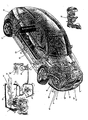
- the Full Saving is composed of mechanical components regenerating the flue gases produced by internal combustion engine.
- the Full Saving turns the flue gas-thermal energy into mechanical energy generated by the compressed air.
- This turbine is composed of two impellers: one is used for regenerating flue gases (impeller 14), the other uses the compressed air (impeller 13).
- the impellers transmit (with their small shafts connected to the impellers in the first section and connected to a gearing with a turn drive "16" in its final section) the rotation power to the flywheel (10) (see legend on page 9 ecc.).
- the impeller (14) of the turbine turbocampound 2 are gathered the flue gases coming from the engine (8).
- the flue gases pass through the impeller (3) of traditional turbine (19) and whenever they get out they pass through the tubing(12) and they get into the turbocampound 2 turbine by activating the impeller (14).Now, the impeller(14) will transmit its rotator movement to the small shaft (17-A) and to the turn drive (16).
- the flue gases get out and go into the piping (5-A) where they encounter in the coupling (6) the compressed air which activated the impeller (
- the compressed air [(13) impeller with a small shaft (17 B) and a gearing combined with the turn drive (16) in the final section gets into the tubing (5) and arrives at the coupling (6) and encounters the flue gases coming from the impeller (14), so they go to the tubing(15) if it needs not producing compressed air, otherwise the transmit will be deviated by the switch valve (24) in the tubing (5B).
- the tubing (5B) lets flue gases and compressed air [coming from the coupling (6)] through the impeller (27).
- the task of this impeller is to activate the compressor(28) producing compressed air that must be sent to the accumulation tanks (25).
- the transmit of the flue gases and compressed air in the piping (5B and 15) is controlled by a switch valve (24).
- the switch valve (24) closes, the passage of the flue gases and the compressed air will be in the tubing (15) (the tubing doesn't feed the impeller 27 in fact this impeller feeds the compressor 28), if not, the switch valve (24) is opened (a request for the production of compressed air)the passage of compressed air and flue gases will be in the tubing (5B).
- This tubing must feed the impeller (27) and this impeller will activate the compressor (28) supplying with other compressed air the accumulation tanks (25), then the rotation cycle of the impeller can start again (13).
- the compressed air produced by the compressor (28) is sent to the pressure regulator (23) by the tubing (26). On its way the compressed air encounters the joint (42).
- the task of the joint is to canalize the compressed air coming from the piping (39-26-40-41) sent to the pressure regulator (23).
- the compressed air reaches the accumulation tank (25) by the tubing (46) where a safety valve (22) assures a working pressure. After having came out of the tank (25) the compressed air reaches the duplex distributor (7) using the tubing (43).
- the compressed air passes through the tubing (9) and gets out and finally feeds the impeller (13) of the turbocampound turbine.
- Full Saving 2 and Full Saving 3 (only for trucks), if you want to produce again compressed air.
- the Full Saving 2 (see table 2) begins working whenever it needs reducing speed or braking, indeed the Full Saving 2 is used as a hydraulic decelerator and also to produce compressed air at the same time.
- the system is applicable to trucks and heavy vehicles, which on flat ways, when they must reduce speed, they use the decelerator and in this way they obtain compressed air without wearing and overheating the brakes.
- the Full Saving 2 (see caption on page 14) produces compressed air that must be sent to Full Saving group (components that reduce the fuel consumptions and reduce the air pollution).
- the Full Saving 2 is composed of a casing (95), where you can find out a scabbard or a jacket (137) and where there is a rack cylinder (138).
- This cylinder send the oil to a particular section (named stage 1), where there are a series of fittings distinguishing the type of slowing-down as needed and producing compressed air at the same time that must be sent to full Saving moderating the wear and the overheating of the brakes. you can get this effect through the rack shaft (138) that pushes the oil from the initial section (from where the oil arrives) to the final one (final section of the first stage).
- This impeller is connected (by means of a speed gearing) to a compressor (100) producing compressed air.
- the oil through a braking sensor will activate the opening of the electro-valve (102) and so doing the oil will flow to the tubing of the return oil (133-135) to accumulation tank (124).
- the opening electro-valves (102 tubing bringing back the hydraulic oil to the accumulation tank) of slowing-down stages have a sensor as to as to eliminate any problem about working, weight, weather conditions.
- This sensor is connected to an anti-blockage station A.B.S. so as to assure a good use of the decelerator even in hard circumstances without running the risk of locking the wheels.
- This device turns thermal energy of the flue gases into vapour kinetic energy.
- the contrivance feeds one or more compressors and produces compressed air that must be sent to the Full Saving contrivance.
- the Full Saving 3 is the last of the optional components recycling the flue gases and turning their heat into compressed air that must be sent to the Full Saving ( to the accumulation tanks 25 exactly, see caption on page 16).
- the flue gases ran through the piping (48) and pass through the coil (56) (which is formed by several turns of the tube) so as to turn water into vapour.
- the separator valve (85) In the container (92) the residual drops of water are separated from the vapour by the separator valve (85) and then the dry saturated vapour can arrive at the impeller (80).
- the dry saturated vapour will activate the impeller (80) and will set in motion the compressor (81) generating compressed air.
- the dry vapour (93) from the container (92) passes through the filter (86) and flows in the piping (84).
- the dry vapour will wait for the opening of the electro-valves (83-78). These electro-valves have the task of deviating the vapour in the tubing (82) without feeding the impeller (80) that activate the compressor (81).
- This process is controlled by the thrust meter (37) which is placed on the Full Saving pressure regulator (23), and where if an excess of compressed air pressure happens, this regulator will send an electric impulse closing the deviating valves (83-78) which will close the tubing (79) and will deviate the vapour on the tubing (82) carrying out the vapour to the container (75)
- the deviating valves (83-78) will close the tubing (78) and will deviate the vapour on the tubing (82) carrying out the vapour to the container (75).
- the deviating valves (83-78) will open and will close the tubing (82). So doing they will oblige the vapour to pass through the tubing (79) which feeds the impeller (80). The impeller (80) will activate the compressor (81) and then the vapour will go into the container (75).
- the container (75) there is a liquid for cooling the vapour coming from the tubing (79) or from the tubing (82) where there is a fan (74) to cool the liquid (water).
- the boiling water is sent again from the container (74) to the container (55) using the piping (62) where there is a pump (69) pushing the water into the container (55).
- the pump is activated by an electric motor (68).Here also it is located a simplex valve (63).If an increase of boiling water volume happens in the container (75) the superabundance will be gathered by the tubing (72) and will pour it in the container (71).
- This container (which is provided with a pump pushing the water and activated with an electric motor (66)) must re-establish the liquid level of the container (55).
- the level condition (61) controls the liquid level in the container (55).
- This level condition by means of an electromechanical control activates the engine (66) feeding the pump (67).
- the pump takes the liquid from the container (71) and send it to
- the safety valves (60-58) will exhaust in the atmosphere the vapour in excess so as to regenerate the working pressure. If there is some anomaly the deviating electro-valves (52-53)will begin working. These valves close and deviate the flue gases in the tubing (49), so the flue gases could't pass in the coil (56) and avoid the formation of vapour in the container (55) and discharge the flue gases directly in the silencer (32) (Full Saving) without making the formation cycle of the Full Saving 3 compressed air.
Landscapes
- Engineering & Computer Science (AREA)
- Chemical & Material Sciences (AREA)
- Combustion & Propulsion (AREA)
- Mechanical Engineering (AREA)
- General Engineering & Computer Science (AREA)
- Supercharger (AREA)
- Control Of The Air-Fuel Ratio Of Carburetors (AREA)
Applications Claiming Priority (2)
| Application Number | Priority Date | Filing Date | Title |
|---|---|---|---|
| IT000003U ITBI20030003U1 (it) | 2003-11-28 | 2003-11-28 | Meccanismo per il risparmio di carburante |
| ITBI20030003U | 2003-11-28 |
Publications (2)
| Publication Number | Publication Date |
|---|---|
| EP1536116A2 true EP1536116A2 (de) | 2005-06-01 |
| EP1536116A3 EP1536116A3 (de) | 2006-05-24 |
Family
ID=34452232
Family Applications (1)
| Application Number | Title | Priority Date | Filing Date |
|---|---|---|---|
| EP04425449A Withdrawn EP1536116A3 (de) | 2003-11-28 | 2004-06-18 | Übertragungsvorrichtung zur Brennstoffsparung |
Country Status (2)
| Country | Link |
|---|---|
| EP (1) | EP1536116A3 (de) |
| IT (1) | ITBI20030003U1 (de) |
Cited By (1)
| Publication number | Priority date | Publication date | Assignee | Title |
|---|---|---|---|---|
| EP1916397A1 (de) | 2006-10-24 | 2008-04-30 | Iveco Motorenforschung AG | Motorgerät mit Wärmerückgewinnungssystem und entsprechendes Wärmerückgewinnungsverfahren |
Citations (5)
| Publication number | Priority date | Publication date | Assignee | Title |
|---|---|---|---|---|
| GB380315A (en) * | 1930-12-15 | 1932-09-15 | Emil Sahli Kummer | Improvements in and relating to power aggregates |
| US4294074A (en) * | 1977-12-12 | 1981-10-13 | Dr. Ing. H.C. F. Porsche Aktiengesellschaft | Drive assembly, especially for motor vehicles |
| US4590766A (en) * | 1983-07-27 | 1986-05-27 | Dr. Ing. H.C.F Porsche Ag | Exhaust gas steam turbine drive unit for automotive vehicles |
| JPH02153227A (ja) * | 1988-12-06 | 1990-06-12 | Mitsubishi Heavy Ind Ltd | 複合機関 |
| DE19742031A1 (de) * | 1997-09-24 | 1999-03-25 | Man B & W Diesel Ag | Mittels Abgasturbolader aufgeladene Brennkraftmaschine mit einer zusätzlichen Abgasenergieumformeinrichtung und Verfahren zum Betrieb dieser Brennkraftmaschine |
-
2003
- 2003-11-28 IT IT000003U patent/ITBI20030003U1/it unknown
-
2004
- 2004-06-18 EP EP04425449A patent/EP1536116A3/de not_active Withdrawn
Patent Citations (5)
| Publication number | Priority date | Publication date | Assignee | Title |
|---|---|---|---|---|
| GB380315A (en) * | 1930-12-15 | 1932-09-15 | Emil Sahli Kummer | Improvements in and relating to power aggregates |
| US4294074A (en) * | 1977-12-12 | 1981-10-13 | Dr. Ing. H.C. F. Porsche Aktiengesellschaft | Drive assembly, especially for motor vehicles |
| US4590766A (en) * | 1983-07-27 | 1986-05-27 | Dr. Ing. H.C.F Porsche Ag | Exhaust gas steam turbine drive unit for automotive vehicles |
| JPH02153227A (ja) * | 1988-12-06 | 1990-06-12 | Mitsubishi Heavy Ind Ltd | 複合機関 |
| DE19742031A1 (de) * | 1997-09-24 | 1999-03-25 | Man B & W Diesel Ag | Mittels Abgasturbolader aufgeladene Brennkraftmaschine mit einer zusätzlichen Abgasenergieumformeinrichtung und Verfahren zum Betrieb dieser Brennkraftmaschine |
Non-Patent Citations (1)
| Title |
|---|
| PATENT ABSTRACTS OF JAPAN vol. 014, no. 404 (M-1018), 31 August 1990 (1990-08-31) & JP 02 153227 A (MITSUBISHI HEAVY IND LTD), 12 June 1990 (1990-06-12) * |
Cited By (2)
| Publication number | Priority date | Publication date | Assignee | Title |
|---|---|---|---|---|
| EP1916397A1 (de) | 2006-10-24 | 2008-04-30 | Iveco Motorenforschung AG | Motorgerät mit Wärmerückgewinnungssystem und entsprechendes Wärmerückgewinnungsverfahren |
| US7954320B2 (en) | 2006-10-24 | 2011-06-07 | Iveco Motorenforschung Ag | Engine apparatus with heat recovery system and relative heat recovery method |
Also Published As
| Publication number | Publication date |
|---|---|
| ITBI20030003U1 (it) | 2005-05-29 |
| EP1536116A3 (de) | 2006-05-24 |
Similar Documents
| Publication | Publication Date | Title |
|---|---|---|
| CN202944330U (zh) | 具有独立的增压器和电动机/发电机的增压器组件 | |
| EP3211195B1 (de) | Integriertes verfahren zum antrieb eines co2-verdichters eines systems zur co2-abscheidung mit verwendung einer abgasturbine eines verbrennungsmotors an bord einer mobilen quelle | |
| AP1050A (en) | Method and device for reaccelerating a vehicle equipped with a high pressure compressor. | |
| CN100412319C (zh) | 空气发动机 | |
| US5708306A (en) | Supplementary power system of an automobile | |
| CN103180584A (zh) | 内燃机的排气制动器控制方法及装置 | |
| CN103547326A (zh) | 废热回收装置 | |
| JPS5810116A (ja) | タ−ボ圧縮器を備えた内燃機関の排気の排出弁の制御方法および装置 | |
| US7021272B2 (en) | Computer controlled multi-stroke cycle power generating assembly and method of operation | |
| CN111911294B (zh) | 包括电动涡轮的内燃热机的四驱混动车辆及对应控制方法 | |
| CN106168158B (zh) | 改进的涡轮增压器系统 | |
| CN104044583A (zh) | 混合动力车辆和通过控制废热回收装置旁路阀的制动方法 | |
| EP3155245B1 (de) | Turbinensystem | |
| CN104763472B (zh) | 用于气动汽车的多缸空气动力发动机总成 | |
| CN202628192U (zh) | 用于气动汽车的多缸空气动力发动机总成 | |
| CN103422892B (zh) | 用于气动汽车的空气分配控制器 | |
| CN103492818A (zh) | 通用热力发动机 | |
| CN1150099C (zh) | 气电混合动力发动机 | |
| EP1536116A2 (de) | Übertragungsvorrichtung zur Brennstoffsparung | |
| CN104005836B (zh) | 可回收制动能量的进气增压机构 | |
| CN107323258B (zh) | 一种汽车能量多级回收储存系统及方法 | |
| CN103206251B (zh) | 可变多缸空气动力发动机 | |
| CN100430581C (zh) | 一种降低车辆能耗的方法及其装置 | |
| US2139090A (en) | Braking | |
| CN102556029B (zh) | 用于控制空气流动的系统和方法 |
Legal Events
| Date | Code | Title | Description |
|---|---|---|---|
| PUAI | Public reference made under article 153(3) epc to a published international application that has entered the european phase |
Free format text: ORIGINAL CODE: 0009012 |
|
| AK | Designated contracting states |
Kind code of ref document: A2 Designated state(s): AT BE BG CH CY CZ DE DK EE ES FI FR GB GR HU IE IT LI LU MC NL PL PT RO SE SI SK TR |
|
| AX | Request for extension of the european patent |
Extension state: AL HR LT LV MK |
|
| PUAL | Search report despatched |
Free format text: ORIGINAL CODE: 0009013 |
|
| AK | Designated contracting states |
Kind code of ref document: A3 Designated state(s): AT BE BG CH CY CZ DE DK EE ES FI FR GB GR HU IE IT LI LU MC NL PL PT RO SE SI SK TR |
|
| AX | Request for extension of the european patent |
Extension state: AL HR LT LV MK |
|
| RIC1 | Information provided on ipc code assigned before grant |
Ipc: F02G 5/04 20060101ALI20060401BHEP Ipc: F02G 5/02 20060101ALI20060401BHEP Ipc: F02B 41/10 20060101ALI20060401BHEP Ipc: F02B 77/00 20060101ALI20060401BHEP Ipc: F02B 73/00 20060101ALI20060401BHEP Ipc: F02B 67/00 20060101AFI20050218BHEP |
|
| AKX | Designation fees paid | ||
| REG | Reference to a national code |
Ref country code: DE Ref legal event code: 8566 |
|
| STAA | Information on the status of an ep patent application or granted ep patent |
Free format text: STATUS: THE APPLICATION IS DEEMED TO BE WITHDRAWN |
|
| 18D | Application deemed to be withdrawn |
Effective date: 20070103 |